Embed Size (px)
Citation preview

US CA
Installation instructionsand User guide
Freestanding cookerOR30SDPWIX model


1Contents
Safety and warnings 2
Installation instructions 8
First use 17
Setting the clock 18
Using your oven 19
Cooking functions 22
Cooking guide 24
Using the electronic timer 26
Automatic cooking 27
Induction cooktop introduction 28
Choosing the right cookware 30
Using your induction cooktop 32
Using your cooktop’s special features 33
Cooking guidelines 35
Using the warming drawer 36
Care and cleaning 38
Cooktop fault codes 48
Troubleshooting 50
Warranty and service 53
Important! SAVE THESE INSTRUCTIONSThe models shown in this User Guide may not be available in all markets and are subject to change at any time. For current details about model and specification availability in your country, please go to our website www.fisherpaykel.com or contact your local Fisher & Paykel dealer.
US CA
2 Safety and warnings
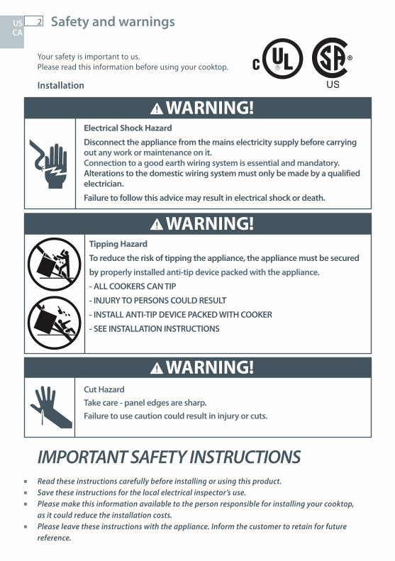
IMPORTANT SAFETY INSTRUCTIONS Read these instructions carefully before installing or using this product. Save these instructions for the local electrical inspector’s use. Please make this information available to the person responsible for installing your cooktop,
as it could reduce the installation costs. Please leave these instructions with the appliance. Inform the customer to retain for future
reference.
WARNING!
Electrical Shock Hazard
Disconnect the appliance from the mains electricity supply before carryingout any work or maintenance on it.Connection to a good earth wiring system is essential and mandatory.Alterations to the domestic wiring system must only be made by a qualified electrician.
Failure to follow this advice may result in electrical shock or death.
WARNING!
Tipping Hazard
To reduce the risk of tipping the appliance, the appliance must be secured
by properly installed anti-tip device packed with the appliance.
- ALL COOKERS CAN TIP
- INJURY TO PERSONS COULD RESULT
- INSTALL ANTI-TIP DEVICE PACKED WITH COOKER
- SEE INSTALLATION INSTRUCTIONS
WARNING!Cut HazardTake care - panel edges are sharp.Failure to use caution could result in injury or cuts.
US CA
WARNING !
Your safety is important to us. Please read this information before using your cooktop.
Installation
RR
3Safety and warnings
IMPORTANT SAFETY INSTRUCTIONS This appliance is to be installed and connected to the electricity supply only by a qualified
technician in compliance with national codes, local regulations and according to these instructions.
Electrical installation (including electrical grounding) must be done in accordance with the National Electrical Code, ANSI/NFPA70 – latest edition and/or local codes. In Canada: Electrical installation must be in accordance with the current CSA C22.1 Canadian Electrical Codes Part 1 and/or local codes.
Failure to install the appliance correctly could invalidate any warranty or liability claims. For personal safety, this appliance must be properly grounded. Do not leave packaging elements (e.g. plastic bags, polystyrene foam, staples, packing straps)
within easy reach of children during or after installation, as these may cause serious injury. Make sure you recycle the packaging material. Before disposing of any appliance, make sure that it can no longer be used and that all hazardous
parts are removed or made harmless, so that children playing with the old appliance cannot harm themselves.
Only genuine replacement parts may be used for servicing the appliance. These are available from your nearest Fisher & Paykel Authorized Service Center.
To eliminate the risk of burns or fire by reaching over heated surface units, cabinet storage space located above the surface units should be avoided. If cabinet storage is to be provided, the risk can be reduced by installing a rangehood that projects horizontally a minimum of 5 inches beyond the bottom of the overhead cabinets.
This appliance is equipped with a four-prong grounding plug (NEMA 14-50P) for your protection against shock hazard and should be plugged directly into a properly grounded socket. Do not under any circumstances cut or remove the fourth (ground) prong from the power plug.
If an external electrical source is utilized, the appliance, when installed, must be electrically grounded in accordance with local codes or, in the absence of local codes, with the national Electrical Code, ANSI/NFPA 70.
The mains electricity switch should always be accessible. When installing or removing the cooker for service, a rolling lift jack should be used. Do not push
against any of the edges of the cooker in an attempt to slide it into or out of the installation. Pushing or pulling a cooker (rather than using a lift jack) also increases the possibility of bending the leg spindles or the internal coupling connectors.
US CA
4 Safety and warnings
Operation and maintenance
WARNING!
Electrical Shock Hazard
Do not cook on a broken or cracked cooktop. If the cooktop should break or crack, cleaning solutions and spillovers may penetrate it and create a risk of electrical shock. Contact a qualified technician immediately.
Failure to follow this advice may result in death or electrical shock.
WARNING!
Health Hazard
Persons with cardiac pacemakers or other electrical implants (such as insulin pumps) must consult with their doctor or implant manufacturer before using this appliance to make sure that their implants will not be affected by the electromagnetic field.
Failure to follow this advice may result in death.
US CA
WARNING!Cut HazardThe razor-sharp blade of a cooktop scraper is exposed when the safety cover is retracted. Use with extreme care and always store safely and out of reach of children.Failure to use caution could result in injury or cuts.
5Safety and warnings
Operation and maintenance
WARNING!
Hot Surface Hazard
DO NOT TOUCH SURFACE UNITS OR AREAS NEAR UNITS OR THE INTERIOR
SURFACES OF THE OVEN. – Surface units may be hot even though they are dark in color. Areas near surface units may become hot enough to cause burns. During and after use, do not touch, or let clothing or other flammable materials contact surface units or areas near units until they have had sufficient time to cool. Among these areas are the glass surfaces within and around the circles and the interior of the oven.Never leave metal objects (such as kitchen utensils) or empty pans on the cooktop as they can become hot very quickly.Beware: magnetisable metal objects worn on the body may become hot in the vicinity of the cooktop. Gold or silver jewellery will not be affected.Keep children away.Handles of saucepans may be hot to touch. Check saucepan handles do not overhang other cooking zones that are on. Keep handles out of reach of children.Do not store flammable items in the oven or warmer drawer.
Failure to follow this advice could result in burns and scalds.
WARNING!Fire Hazard
Never leave the appliance unattended when in use. Boilover causes smoking and greasy spillovers that may ignite.NEVER try to extinguish a fire with water. Switch the appliance off at the wall and then cover the flame with a lid or fire blanket.
Failure to follow this advice may result in overheating, burning, and injury.
US CA
6 Safety and warnings
Operation and maintenance
IMPORTANT SAFETY INSTRUCTIONS This appliance is designed and manufactured solely for the cooking of domestic (household)
food and is not suitable for any non-domestic application and therefore should not be used in a commercial environment. The appliance warranty will be void if the appliance is used within a non-domestic environment (i.e. a semi commercial, commercial or communal environment).
Proper installation — Be sure your appliance is properly installed and grounded by a qualified technician.
Never use your appliance for warming or heating the room. Do not leave children alone — Children should not be left alone or unattended in the area where
the appliance is in use. They should never be allowed to sit or stand on any part of the appliance. Wear proper apparel — Loose-fitting or hanging garments should never be worn while using the
appliance. User servicing — Do not repair or replace any part of the appliance unless specifically
recommended in the manual. All other servicing should be referred to a qualified technician. Storage in or on appliance — Flammable materials should not be stored in an oven or near
surface units. Do not use water on grease fires — Smother fire or flame or use dry chemical or foam-type
extinguisher. Use only dry potholders — Moist or damp potholders on hot surfaces may result in burns from
steam. Do not let potholder touch hot heating elements. Do not use a towel or other bulky cloth. Use proper pan size — This appliance is equipped with one or more surface units of different
size. Select utensils having flat bottoms large enough to cover the surface unit heating element. The use of undersized utensils will expose a portion of the heating element to direct contact and may result in ignition of clothing. Proper relationship of utensil to cooking zone will also improve efficiency.
Never leave surface units unattended at high heat settings – Boilover causes smoking and greasy spillovers that may ignite.
Utensil handles should be turned inward and not extend over adjacent surface units — To reduce the risk of burns, ignition of flammable materials, and spillage due to unintentional contact with the utensil, the handle of a utensil should be positioned so that it is turned inward, and does not extend over adjacent surface units.
Do not cook on broken cooktop — If cooktop should break, cleaning solutions and spillovers may penetrate the broken cooktop and create a risk of electric shock. Contact a qualified technician immediately.
Clean cooktop with caution — If a wet sponge or cloth is used to wipe spills on a hot cooking area, be careful to avoid steam burn. Some cleaners can produce noxious fumes if applied to a hot surface.
Caution: Do not leave food or cooking utensils etc. in the oven during self-cleaning.
US CA
7
IMPORTANT SAFETY INSTRUCTIONS CAUTION - Do not store items of interest to children in cabinets above an appliance - children
climbing on the appliance to reach items could be seriously injured. If the appliance is malfunctioning, it will display an alert code: first note down the alert code (see
section ‘Alert codes’ in this manual), then contact your Authorized Service Center or Customer Care to arrange for service. Do not use your appliance until it has been repaired by a Fisher & Paykel authorized technician.
Never use your appliance as a work or storage surface. Never leave any objects or utensils on the appliance. Do not place or leave any magnetizable objects (eg credit cards, memory cards) or electronic
devices (eg computers, MP3 players) near the appliance, as they may be affected by its electromagnetic field.
We recommend using plastic or wooden kitchen utensils for cooking with your induction cooktop. Do not place or leave aluminum foil on the cooktop. After use, always turn off the cooking zones as described in this manual. Do not rely on the pan
detection feature to turn off the cooking zones when you remove the pans. Children or persons with a disability which limits their ability to use the appliance should have a
responsible and competent person to instruct them in its use. The instructor should be satisfied that they can use the appliance without danger to themselves or their surroundings.
Do not use a steam cleaner to clean your cooktop. Do not place or drop heavy objects on your cooktop. Do not stand on your cooktop. Do not stand, sit or step or place heavy weights on the oven door. Do not use pans with jagged edges or drag pans across the ceramic glass surface as this can
scratch the glass. Do not use scourers or any other harsh/abrasive cleaning agents to clean your cooktop, as these
can scratch the ceramic glass. Make sure the electrical cables connecting other appliances in the proximity of the cooker cannot
come into contact with the hob or become entrapped in the oven door. Fire risk! Do not store flammable material in the oven or warming drawer. Do not line the oven walls with aluminium foil. Do not place shelves, broiler pan, pans or other
cooking utensils on the oven floor. Stand away from the cooker when opening the door. Hot air or steam which escapes can cause
burns. Always use oven gloves or mitts when placing or removing items in the oven. Never touch the appliance with wet hands. After use, ensure the dials are all in the `OFF’ position. The manufacturer declines all liability for injury to person or damage to property caused by
incorrect or improper use of the appliance. Always turn off the mains power to the cooker prior to cleaning or maintenance.
Safety and warnings
Operation and maintenance
US CA
8US CA
Installation instructions
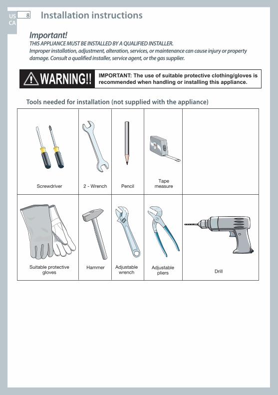
Important! THIS APPLIANCE MUST BE INSTALLED BY A QUALIFIED INSTALLER.Improper installation, adjustment, alteration, services, or maintenance can cause injury or property damage. Consult a qualified installer, service agent, or the gas supplier.
Screwdriver 2 - WrenchTape
measurePencil
Adjustablepliers
Adjustablewrench
Suitable protectivegloves Drill
Hammer
Tools needed for installation (not supplied with the appliance)
IMPORTANT: The use of suitable protective clothing/gloves is recommended when handling or installing this appliance.
9
Dotted line showingthe position of thecooker when installed
Area forelectricalconnection
Area forelectricalconnection
5 7 / 1
6” (1
38 m
m) t
o6
1 / 8” (
155.
5 m
m) (
*)
(*) Depending on feet adjustment
US CA
Installation instructions
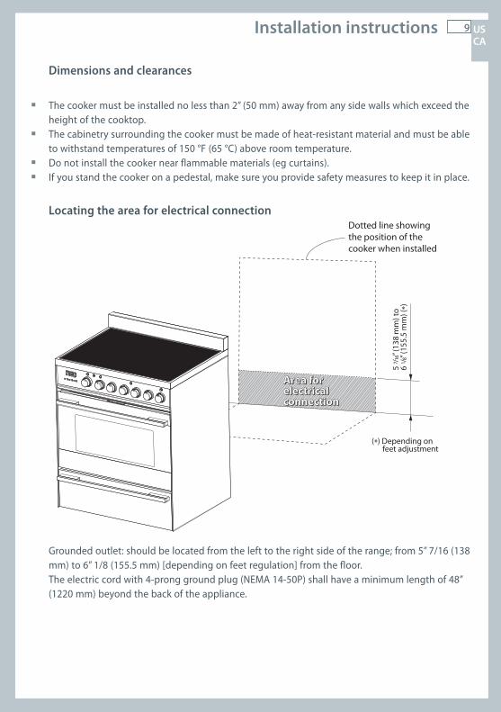
Dimensions and clearances
The cooker must be installed no less than 2” (50 mm) away from any side walls which exceed the height of the cooktop.
The cabinetry surrounding the cooker must be made of heat-resistant material and must be able to withstand temperatures of 150 °F (65 °C) above room temperature.
Do not install the cooker near flammable materials (eg curtains). If you stand the cooker on a pedestal, make sure you provide safety measures to keep it in place.
Grounded outlet: should be located from the left to the right side of the range; from 5” 7/16 (138 mm) to 6” 1/8 (155.5 mm) [depending on feet regulation] from the floor.
The electric cord with 4-prong ground plug (NEMA 14-50P) shall have a minimum length of 48” (1220 mm) beyond the back of the appliance.
Locating the area for electrical connection
10US CA
Installation instructions
2” min.(50 mm)
13” max.(330 mm)
0”(0 mm)
0” (0 mm)
30” m
in.
(672
mm
)
36”
(914
mm
)
19 5/8” min.(500 mm)
18” m
in.
(457
mm
)
Cooker overall dimensions [mm]• height (without backguard):
MIN 35 21/32” (906 mm) - MAX 36 11/32” (923 mm)
• product width: 29 7/8” (759 mm)• depth: 24 13/64” (615 mm)• backguard (height): 3” (76 mm)
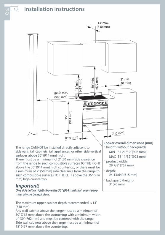
The range CANNOT be installed directly adjacent to sidewalls, tall cabinets, tall appliances, or other side vertical surfaces above 36” (914 mm) high.There must be a minimum of 2” (50 mm) side clearance from the range to such combustible surfaces TO THE RIGHT above the 36” (914 mm) high countertop; or there must be a minimum of 2” (50 mm) side clearance from the range to such combustible surfaces TO THE LEFT above the 36” (914 mm) high countertop.
Important!One side (left or right) above the 36” (914 mm) high countertop must always be kept clear.
The maximum upper cabinet depth recommended is 13” (330 mm). Any wall cabinet above the range must be a minimum of 30” (762 mm) above the countertop with a minimum width of 30” (762 mm) and must be centered with the range. Side wall cabinets above the range must be a minimum of 18” (457 mm) above the countertop.

11 US CA
Installation instructions
Important! To prevent damaging the adjustable feet or lower trim, ensure the cooker is always lifted by two people.
Do not lift the cooker by the door handles.DO NOT DRAG the cooker. Lift the feet clear of the floor.
Take extra care not to damage the door sensor (top right of oven).
Moving the cooker
Correctly lifting the cooker
Incorrectly moving the cookerIncorrectly lifting the cooker
Fixing the backguard
It is mandatory to install the backguard. Before installing the cooker, assemble the backguard “C” .
The backguard “C” can be found packed with the cooker.
1 Before assembling, remove any protective film/adhesive tape.
2 Assemble the backguard “C” as shown 3 Screw in the two screws “A”, interposing
the spacers.4 Screw in the central screw “B”.
Assembling the backguard
C
A
B
12US CA
Installation instructions
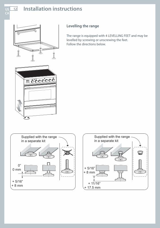
Levelling the range
The range is equipped with 4 LEVELLING FEET and may be levelled by screwing or unscrewing the feet.Follow the directions below.
Supplied with the rangein a separate kit
Supplied with the rangein a separate kit
0”0 mm
+ 5/16”+ 8 mm
+ 5/16”+ 8 mm
+ 11/16”+ 17.5 mm
13 US CA
Installation instructions
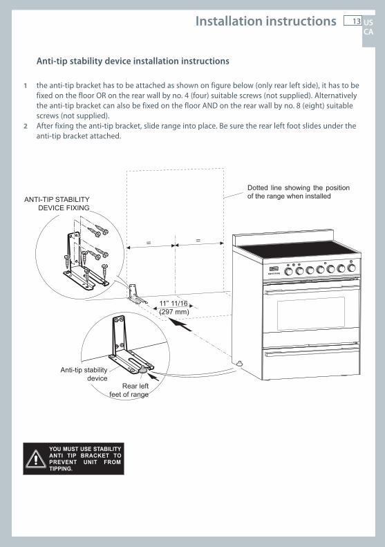
YOU MUST USE STABILITYANTI TIP BRACKET TOPREVENT UNIT FROMTIPPING.
= =
Dotted line showing the position of the range when installedANTI-TIP STABILITY
DEVICE FIXING
Anti-tip stabilitydevice
Rear leftfeet of range
11” 11/16(297 mm)
Anti-tip stability device installation instructions
1 the anti-tip bracket has to be attached as shown on figure below (only rear left side), it has to be fixed on the floor OR on the rear wall by no. 4 (four) suitable screws (not supplied). Alternatively the anti-tip bracket can also be fixed on the floor AND on the rear wall by no. 8 (eight) suitable screws (not supplied).
2 After fixing the anti-tip bracket, slide range into place. Be sure the rear left foot slides under the anti-tip bracket attached.
14
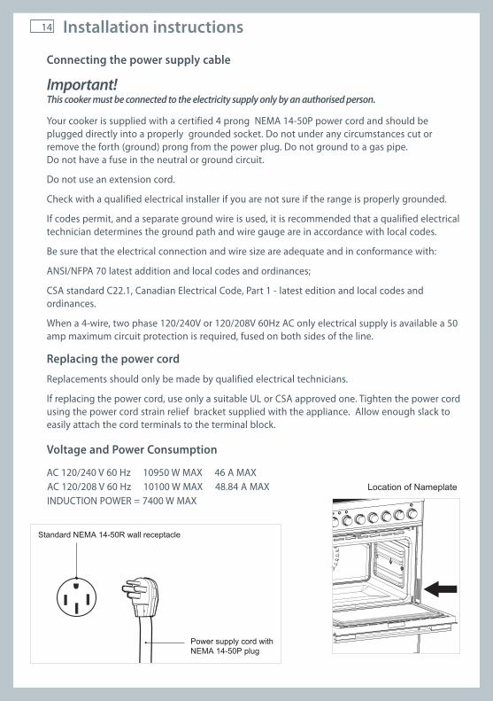
Connecting the power supply cable
Important!This cooker must be connected to the electricity supply only by an authorised person.
Your cooker is supplied with a certified 4 prong NEMA 14-50P power cord and should be plugged directly into a properly grounded socket. Do not under any circumstances cut or remove the forth (ground) prong from the power plug. Do not ground to a gas pipe. Do not have a fuse in the neutral or ground circuit.
Do not use an extension cord.
Check with a qualified electrical installer if you are not sure if the range is properly grounded.
If codes permit, and a separate ground wire is used, it is recommended that a qualified electrical technician determines the ground path and wire gauge are in accordance with local codes.
Be sure that the electrical connection and wire size are adequate and in conformance with:
ANSI/NFPA 70 latest addition and local codes and ordinances;
CSA standard C22.1, Canadian Electrical Code, Part 1 - latest edition and local codes and ordinances.
When a 4-wire, two phase 120/240V or 120/208V 60Hz AC only electrical supply is available a 50 amp maximum circuit protection is required, fused on both sides of the line.
Replacing the power cord
Replacements should only be made by qualified electrical technicians.
If replacing the power cord, use only a suitable UL or CSA approved one. Tighten the power cord using the power cord strain relief bracket supplied with the appliance. Allow enough slack to easily attach the cord terminals to the terminal block.
Voltage and Power Consumption
AC 120/240 V 60 Hz 10950 W MAX 46 A MAX AC 120/208 V 60 Hz 10100 W MAX 48.84 A MAX INDUCTION POWER = 7400 W MAX
Installation instructions
Power supply cord withNEMA 14-50P plug
Standard NEMA 14-50R wall receptacle
Location of Nameplate

15Installation instructions
Wiring diagram
ELEC
TRIC
DIA
GR
AM
KEY
IU
IND
UC
TIO
N U
NIT
RSI
R
OTA
RY
SE
LEC
TOR
INTE
RFA
CE
IUTB
IN
DU
CTI
ON
UN
IT T
ER
MIN
AL
BLO
CK
IHTO
IN
DU
CTI
ON
HO
B T
HE
RM
AL
OV
ER
LOA
DO
L O
VE
N L
AM
PE6
1 R
ELA
YC
E C
IRC
ULA
R E
LEM
EN
TG
E B
RO
IL E
LEM
EN
TTE
TO
P E
LEM
EN
TB
E-IN
T B
OTT
OM
ELE
ME
NT
INT.
BE-
EXT
BO
TTO
M E
LEM
EN
T E
XT.
TPL
THE
RM
OS
TAT
PIL
OT
LAM
PD
SPL
DO
OR
SA
FETY
PIL
OT
LAM
PC
F C
OO
LIN
G F
AN
OF
OV
EN
FA
NER
E
NE
RG
Y R
EG
ULA
TOR
DLM
D
OO
R L
OC
K M
OTO
RSL
/U
STA
TUS
LO
CK
/UN
LOC
K
LPL
LIN
E P
ILO
T LA
MP
WD
W
AR
MIN
G D
RAW
ER
ELE
ME
NT
ST
SA
FETY
TH
ER
MO
STA
TEL
.P
ELE
CTR
ON
IC P
RO
GR
AM
ME
RSD
D
OO
R S
TATU
S, O
PE
N/C
LOS
ED
OD
L O
VE
N D
OO
R L
ATC
HA
S A
IR S
WIT
CH
CO
NN
ECTI
ON
S O
N P
RO
GR
AM
MER
PN
/PL
SU
PP
LYK
1 P
RO
GR
AM
TH
ER
MO
STA
T R
ELA
Y1
K2
CO
OLI
NG
/OV
EN
FA
N R
ELA
Y2
K3
DO
OR
LO
CK
/UN
LOC
K R
ELA
Y3
PHV
FUN
CTI
ON
STA
TEX0
TH
ER
MO
STA
T E
NC
OD
ER
X1
FUN
CTI
ON
S E
NC
OD
ER
P4
PR
OB
EP5
B
WIR
ES
P5B
(1)+
P5B
(2)+
P5B
(3)
LÉG
END
E D
U S
CH
ÉMA
ÉLEC
TRIQ
UE
IU
IND
UC
TIO
N U
NIT
RSI
R
OTA
RY
SE
LEC
TOR
INTE
RFA
CE
IUTB
IN
DU
CTI
ON
UN
IT T
ER
MIN
AL
BLO
CK
IHTO
IN
DU
CTI
ON
HO
B T
HE
RM
AL
OV
ER
LOA
DO
L LA
MP
E D
U F
OU
RE6
1 R
ELA
ISC
E É
LÉM
EN
T C
IRC
ULA
IRE
GE
ÉLÉ
ME
NT
CH
AU
FFA
NT
DE
GR
ILTE
É
LÉM
EN
T C
HA
UFF
AN
T S
UP
ÉR
IEU
RB
E-IN
T É
LÉM
EN
T IN
FÉR
IEU
R IN
T.B
E-EX
T É
LÉM
EN
T IN
FÉR
IEU
R E
XT.
TPL
VO
YAN
T D
E T
HE
RM
OS
TAT
DSP
L V
OYA
NT
DE
SÉ
CU
RIT
É D
E L
A P
OR
TEC
F V
EN
TILA
TEU
R D
E R
EFR
OID
ISS
EM
EN
TO
F V
EN
TILA
TEU
R D
U F
OU
RER
R
ÉG
ULA
TEU
R D
’EN
ER
GIE
DLM
M
OTE
UR
DE
VE
RR
OU
ILLA
GE
PO
RTE
DU
FO
UR
SL/U
É
TAT
VE
RR
OU
ILLA
GE
/DÉ
VE
RR
OU
ILLA
GE
LPL
VO
YAN
T D
E F
ON
CTI
ON
NE
ME
NT
WD
É
LÉM
EN
T D
U T
IRO
IR D
E M
AIN
TIE
N A
U C
HA
UD
ST
THE
RM
OS
TAT
DE
SÉ
CU
RIT
ÉEL
.P
PR
OG
RA
MM
ATE
UR
ÉLE
CTR
ON
IQU
ESD
É
TAT
PO
RTE
DU
FO
UR
, OU
VE
RTE
/FE
RM
ÉE
OD
L LO
QU
ET
DE
LA
PO
RTE
DU
FO
UR
AS
INTE
RR
UP
TEU
R D
’AIR
CO
NN
EXIO
NS
SUR
LE
PRO
GR
AM
MAT
EUR
PN/P
L A
LIM
EN
TATI
ON
K1
RE
LAIS
1 D
E T
HE
RM
OS
TAT
DE
PR
OG
RA
MM
ATE
UR
K2
RE
LAIS
2 D
E V
EN
TILA
TEU
R D
E R
EFR
OID
ISS
./DU
FO
UR
K3
RE
LAIS
3 D
E V
ER
RO
UIL
LAG
E/D
ÉV
ER
RO
UIL
LAG
E P
OR
TEPH
V É
TAT
DE
FO
NC
TIO
NX0
E
NC
OD
EU
R D
E T
HE
RM
OS
TAT
X1
EN
CO
DE
UR
DE
FO
NC
TIO
NS
P4
SO
ND
EP5
B
CÂ
BLE
S P
5B(1
)+P
5B(2
)+P
5B(3

US CA
17
111213
First use
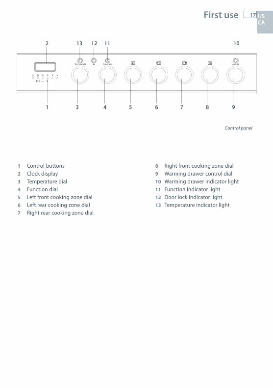
Control panel
1
1 Control buttons2 Clock display3 Temperature dial4 Function dial5 Left front cooking zone dial6 Left rear cooking zone dial7 Right rear cooking zone dial
8 Right front cooking zone dial9 Warming drawer control dial10 Warming drawer indicator light11 Function indicator light12 Door lock indicator light13 Temperature indicator light
2
3 4 5 6 7 8 9
10
US CA

18 Setting the clock
Clock display and control buttons
Buttons
1576102
CP_OR90PYRO_GASTITLE:
DRAWN: DATE:
XXXXXX
L PALMER 21/11/12
FISHER & PAYKEL APPLIANCES LIMITED
FOR PART:
GRAPHICS NO: REVISION:
REVISIONS
REVISION NOTES:
DRWN DATE CHKD ECN REV
NOTES1. Laser marked
2.
3.
4.
5.
6.
LEP 21/11/12 KDM 01
© COPYRIGHT FISHER & PAYKEL APPLIANCES LTD. ALL RIGHTS RESERVED
GRAPHIC IS CORRECT IN SIZE AND SCALE WHEN LINE LENTH IS CORRECT
200mm
sets the timer
1576102
CP_OR90PYRO_GASTITLE:
DRAWN: DATE:
XXXXXX
L PALMER 21/11/12
FISHER & PAYKEL APPLIANCES LIMITED
FOR PART:
GRAPHICS NO: REVISION:
REVISIONS
REVISION NOTES:
DRWN DATE CHKD ECN REV
NOTES1. Laser marked
2.
3.
4.
5.
6.
LEP 21/11/12 KDM 01
© COPYRIGHT FISHER & PAYKEL APPLIANCES LTD. ALL RIGHTS RESERVED
GRAPHIC IS CORRECT IN SIZE AND SCALE WHEN LINE LENTH IS CORRECT
200mm
sets the cooking time
1576102
CP_OR90PYRO_GASTITLE:
DRAWN: DATE:
XXXXXX
L PALMER 21/11/12
FISHER & PAYKEL APPLIANCES LIMITED
FOR PART:
GRAPHICS NO: REVISION:
REVISIONS
REVISION NOTES:
DRWN DATE CHKD ECN REV
NOTES1. Laser marked
2.
3.
4.
5.
6.
LEP 21/11/12 KDM 01
© COPYRIGHT FISHER & PAYKEL APPLIANCES LTD. ALL RIGHTS RESERVED
GRAPHIC IS CORRECT IN SIZE AND SCALE WHEN LINE LENTH IS CORRECT
200mm
sets the stop time for automatic cooking
set the oven temperature / select Celsius or Fahrenheit
1576102
CP_OR90PYRO_GASTITLE:
DRAWN: DATE:
XXXXXX
L PALMER 21/11/12
FISHER & PAYKEL APPLIANCES LIMITED
FOR PART:
GRAPHICS NO: REVISION:
REVISIONS
REVISION NOTES:
DRWN DATE CHKD ECN REV
NOTES1. Laser marked
2.
3.
4.
5.
6.
LEP 21/11/12 KDM 01
© COPYRIGHT FISHER & PAYKEL APPLIANCES LTD. ALL RIGHTS RESERVED
GRAPHIC IS CORRECT IN SIZE AND SCALE WHEN LINE LENTH IS CORRECT
200mm
decreases the time and temperature
1576102
CP_OR90PYRO_GASTITLE:
DRAWN: DATE:
XXXXXX
L PALMER 21/11/12
FISHER & PAYKEL APPLIANCES LIMITED
FOR PART:
GRAPHICS NO: REVISION:
REVISIONS
REVISION NOTES:
DRWN DATE CHKD ECN REV
NOTES1. Laser marked
2.
3.
4.
5.
6.
LEP 21/11/12 KDM 01
© COPYRIGHT FISHER & PAYKEL APPLIANCES LTD. ALL RIGHTS RESERVED
GRAPHIC IS CORRECT IN SIZE AND SCALE WHEN LINE LENTH IS CORRECT
200mm
increases the time and temperature
sets the Self Clean time
starts the oven/starts the Self Clean cycle
Illuminated symbols
If the display shows It means that... For more information
flashing 12:00 The clock needs to be set. See instructions below.
steadily lit The oven is set for automatic cooking.
See section ‘Automatic cooking’flashing and beeping Automatic cooking has finished
steadily lit The timer is set See section ‘Using the electronic timer’
steadily lit The oven is heating up See section ‘Using your oven’
To set the clock
When the power to the appliance is turned on or restored after a power failure 12:00 will flash in the display.
1 Press
12:00 A
and
12:00 A
together - the display will stop flashing. The clock is now set for 12:00.2 Press
12:00 A
and
12:00 A
together again to change the time. The display will flash3 Rotate the temperature dial or press
12:00 A
and
12:00 A
to set the time. After a few minutes the display will be steadily lit, showing the time is set.
To change the time
1 Press
12:00 A
and
12:00 A
together. The display will flash.2 Rotate the temperature dial or press
12:00 A
and
12:00 A
to set the time.
After a few seconds the display will remain steadily lit, showing the time is set.
Note: when the indicator light is at the top the time is set for am when the indicator light is at the bottom the time is set for pm.
1576102
CP_OR90PYRO_GASTITLE:
DRAWN: DATE:
XXXXXX
L PALMER 21/11/12
FISHER & PAYKEL APPLIANCES LIMITED
FOR PART:
GRAPHICS NO: REVISION:
REVISIONS
REVISION NOTES:
DRWN DATE CHKD ECN REV
NOTES1. Laser marked
2.
3.
4.
5.
6.
LEP 21/11/12 KDM 01
© COPYRIGHT FISHER & PAYKEL APPLIANCES LTD. ALL RIGHTS RESERVED
GRAPHIC IS CORRECT IN SIZE AND SCALE WHEN LINE LENTH IS CORRECT
200mm
12:00 A
12:00 A12:00 A
Indicates AM
Indicates AM
Indicates PM
Indicates PM
12:00 A
12:00 A
US CA

19Using your oven
Before using your new oven, please:
1 Read this user guide, taking special note of the ‘Safety and warnings’ section.2 Remove all accessories and packaging. Peel the protective film off all surfaces and accessories.3 Set the clock. The oven will not work until the clock has been set. See ‘To set the clock’.4 Slide in the shelves you will need, making sure that: they are between the two wires of a shelf position; the stop notches point down; the bigger guard rail is at the back.5 Heat the oven on maximum for:
60 minutes in the position
30 minutes in the position 15 minutes in the position
There will be a distinctive smell while you are conditioning your oven. This is normal, but make sure your kitchen is well ventilated during the conditioning.
6 Once cooled, wipe out the oven with a damp cloth and mild detergent, and dry thoroughly.
Correct position of shelves
12:00 A
US CA
Bigger guard rail Stop notch
Stopnotch
20 Using your oven
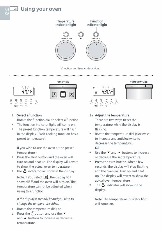
Function and temperature dials
Tmperature indicator light
Function indicator light
US CA
410 430F FF 190OFF
410 430F FF 190OFF
FUNCTION TEMPERATURE
1 Select a function Rotate the function dial to select a function The function indicator light will come on. The preset function temperature will flash
in the display. (Each cooking function has a preset temperature).
If you wish to use the oven at the preset temperature -
Press the
12:00 A
button and the oven will turn on and heat up. The display will revert to show the actual oven temperature.
the
12:00 A
indicator will show in the display.
Note: if you select
210 225C CC 89
, the display will show dEFand the oven will turn on. The temperature cannot be adjusted when using this function.
If the display is steadily lit and you wish to change the temperature either:
1 Rotate the temperature dial; or2 Press the
12:00 A
12:00 A
button and use the
12:00 A
and
12:00 A
buttons to increase or decrease temperature.
2a Adjust the temperature There are two ways to set the
temperature while the display is flashing:
Rotate the temperature dial (clockwise to increase and anticlockwise to decrease the temperature);
OR Use the
12:00 A
and
12:00 A
buttons to increase or decrease the set temperature.
Press the
12:00 A
button. After a few seconds, the display will stop flashing and the oven will turn on and heat up. The display will revert to show the actual oven temperature.
The
12:00 A
indicator will show in the display.
Note: The temperature indicator light will come on.

21Using your oven
410 430F FF 190OFF
410 430F FF 190OFF
FUNCTION
3 When the oven is preheating and during cooking
The
12:00 A
indicator will show in the display. When the oven has reached the set
temperature the
12:00 A
indicator and the temperature indicator light will go out.
Note: these indicators may turn on and off during cooking as the oven maintains the set temperature.
5 When you have finished cooking Turn the function dial to OFF to turn the
oven off.
Note: if you change functions during cooking (eg from BAKE to BROIL) you will need to press the
12:00 A
button again.
4a To check the set temperature Press the
12:00 A
12:00 A
button. The display will flash showing the set
temperature. After a few seconds the display will return
to the actual oven temperature and the display will be steadily lit.
4b To check the time of day Press the
12:00 A
button. After a few seconds the display will show
the oven temperature again.
US CA

22 Cooking functions
OVEN LAMP
Only the oven light comes on. It remains on in all the cooking functions.
DEFROST
this is not a cooking functionOnly the oven fan comes on. The fan circulates air around the oven, speeding up the defrosting process by approximately 30%. Note: this function is not for cooking food.
FAN FORCED
The circular heating element and the fan come on. The oven set on FAN FORCED can cook several different foods together. Use FAN FORCED for multi-shelf cooking.
BAKE
The upper and lower heating elements come on. BAKE is the traditional method of cooking. It is best to cook on only one shelf at a time in this function. Ideal for large cakes and dishes that bake for several hours.
FAN BAKE
The upper and lower heating elements and the fan come on. Ideal for dishes like lasagne that need to brown on top and also single trays of small cakes or biscuits that bake in less than an hour.
BROIL
Broil is the most suitable function for ‘finishing off’ many meals, for example browning the topof potato gratin and frittata. Use Broil to toast bread or to broil your favourite chicken, fish andsteak. Use with the oven door closed. For best results, use the topmost shelf position when you want quick browning (eg toast).
FAN BROIL
Both the broil element and the fan come on. Use with the oven door closed. Ideal for roasting tender cuts of meat and poultry. Use lower shelf positions for larger items eg a whole chicken.
US CA
23Cooking functions
410 430F FF 190OFF
SELF CLEAN
this is not a cooking functionThe oven heats to a high temperature, reducing food residue to a fine ash that can be wiped out with a damp cloth.
Important! Do not leave food or cooking utensils etc. in the oven during self-cleaning.
Important!Safe food handling: leave food in the oven for as short a time as possible before and after cooking or defrosting. This is to avoid contamination by organisms which may cause food poisoning. Take particular care during warmer weather.
Always use oven mitts when placing or removing items from the oven.
US CA
24 Cooking guide
Changing the oven from Celsius to Fahrenheit
You can set your oven to display the temperature in Fahrenheit or Celsius.1 Select a cooking function.2 While the display is flashing, press
12:00 A
to reduce the oven to the minimum temperature (120 oF / 50 oC).3 Press
12:00 A
.4 Press and hold the
12:00 A
12:00 A
button until C or F flashes in the display5 Press the
12:00 A
12:00 A
button and to change between Celsius (C ) and Fahrenheit (F). After a few moments the oven will turn off and the display will show the time of day. Turn the function dial back to OFF.
Cooking Guide
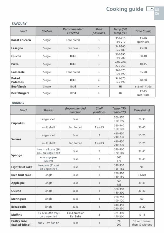
The settings in the following chart are guidelines only. Follow the instructions in your recipe or on packaging and be prepared to adjust the oven settings and baking times to achieve the bestpossible results for you.
Shelf positions are counted from the oven floor up (1 is the lowest, 5 is the highest). Arrange oven shelves before you turn the oven on, then preheat the oven to the desired
temperature. Due to the width of the oven, a single shelf can usually accommodate double the standard
recipe. Always preheat the oven before baking. Do not place anything, including water or ice, on the oven floor. Keep the door completely shut when broiling foods. Do not open the door during the first 3/4 of baking time.
Always cook and broil with the oven door fully closed. If the door stays open “door” flashes on the display and after some minutes an audible warning
sounds for about 30 seconds. To silence the beep press any button.
Note: The heating elements work even with the door open and this signal just indicates that energy is being wasted and the control panel/dials are being excessively heated.
US CA
25Cooking guide
SAVOURY
BAKING
Food Shelves Recommended Function
Shelf positions
Temp (°F) Temp (°C) Time (mins)
Roast Chicken Single Fan Forced 3 350-410 180-210
15-20min/450g
Lasagne Single Fan Bake 3 345-360 175-180 45-50
Quiche Single Bake 1 360-390 180-200 30-40
Pizza Single Bake 3 430- 480 225-250 10-15
Casserole Single Fan Forced 3 340-370 170-190 55-70
BakedPotatoes
Single Bake 4 345-370 175-190 40-50
Beef Steak Single Broil 4 Hi 6-8 min / side
Beef Burgers Single Broil 4 Hi 12-15min / side
Food Shelves Recommended Function
Shelf positions
Temp (°F) Temp (°C) Time (mins)
Cupcakessingle shelf Bake 2 360-370
180-190 20-30
multi shelf Fan Forced 1 and 3 320-340 160-170 30-40
Sconessingle shelf Bake 2 410-450
210-230 15-20
multi shelf Fan Forced 1 and 3 410-450 210-230 15-20
Sponge
two small pans (20 cm), on single shelf Bake 2 340-360
170-180 30-45
one large pan (26 cm) Bake 2 345
175 30-40
Light fruit cake two pans (21 cm) on single shelf Bake 2 310-330
155-165 90
Rich fruit cake Single Bake 2 270-300 130-150 3-6 hrs
Apple pie Single Bake 1 365185 35-45
Quiche Single Bake 1 360-390 180-200 30-40
Meringues Single Bake 1 200-250 100-120 60
Bread rolls Single Bake 1 410-450 210-230 15-20
Muffins 2 x 12 muffin trays on single shelf
Fan Forced or Fan Bake 3 375-390
190-200 10-15
Pastry case(baked ‘blind’)
one 21 cm flan tin Bake 1 390200
10 with beans, then 10 without
US CA
26 Using the electronic timer
12:00 A
US CA
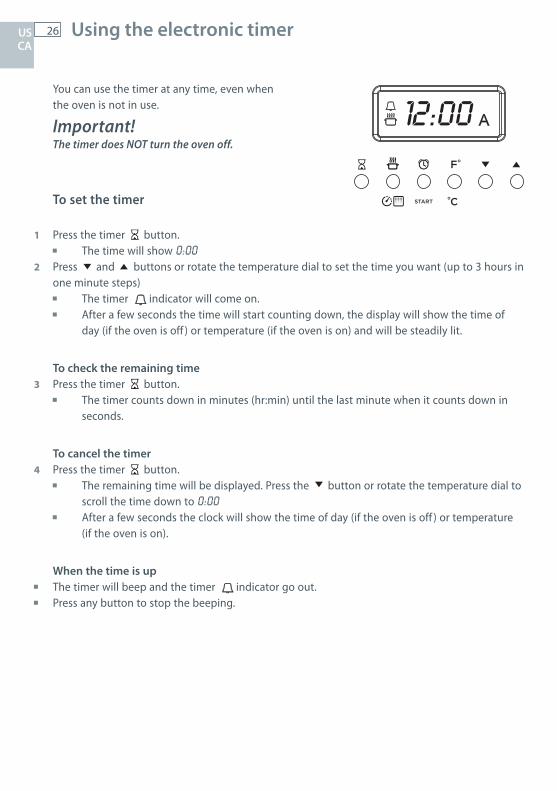
You can use the timer at any time, even whenthe oven is not in use.
Important!The timer does NOT turn the oven off.
To set the timer
1 Press the timer
12:00 A
button. The time will show 0:002 Press
12:00 A
and
12:00 A
buttons or rotate the temperature dial to set the time you want (up to 3 hours in one minute steps)
The timer 12:00 A indicator will come on.
After a few seconds the time will start counting down, the display will show the time of day (if the oven is off ) or temperature (if the oven is on) and will be steadily lit.
To check the remaining time3 Press the timer
12:00 A
button. The timer counts down in minutes (hr:min) until the last minute when it counts down in seconds.
To cancel the timer4 Press the timer
12:00 A
button. The remaining time will be displayed. Press the
12:00 A
button or rotate the temperature dial to scroll the time down to 0:00
After a few seconds the clock will show the time of day (if the oven is off ) or temperature (if the oven is on).
When the time is up The timer will beep and the timer 12:00 A
indicator go out. Press any button to stop the beeping.

27
12:00 A
Automatic cooking US CA
To set the oven for automatic cooking
You can set the oven to automatically turn on later, cook for a preset time (cooking time), then automatically turn off at a preset stop time. Alternatively you can simply set the time of day you wish to the oven to turn off.
1 Set the oven Check the clock shows the correct time (eg 12:07). Select the function and set the temperature. The Function indicator light will come on. Press
12:00 A
. The oven will turn on.2 Set the cooking time Decide how long the food will take to cook, allowing time for preheating if necessary (eg 40 minutes). Press
12:00 A
. Use
12:00 A
and
12:00 A
or rotate the temperature dial to set the cooking time. 12:00 A will show in the display.
3 Set the stop time Decide when you want your food to be ready by (eg 13:30). Press
12:00 A
. Use
12:00 A
and
12:00 A
or rotate the temperature dial to set the stop time.Note: The time indicator will tell you if you have set the time for am or pm.
You can turn the oven on manually and set it to turn off automatically by setting the stop time(step 3 above).
When automatic cooking is set If there is time before cooking starts, the oven will turn off and the pre-set temperature and12:00 A
will show in the clock display, indicating the oven is set for automatic cooking. Note: the cooling fan and oven light may stay on.
The oven will automatically turn on at the required time (eg 12:50) and turn off at the set stop time (eg 13:30). To see the remaining cooking time, press
12:00 A
. To see the set stop time, press
12:00 A
.
To cancel automatic cooking1 Press and hold
12:00 A
and
12:00 A
together for 3 seconds.2 Turn the function dial to OFF.
When the stop time is reached The oven will turn off, the timer will beep. The display will show End and the12:00 A will flash.
1 Press any button to stop the beeping.2 Turn the function dial to OFF.
Indicates AM
Indicates PM12:00 A
28 Induction cooktop introduction
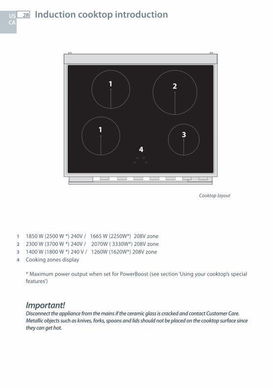
1 1850 W (2500 W *) 240V / 1665 W (2250W*) 208V zone2 2300 W (3700 W *) 240V / 2070W ( 3330W*) 208V zone3 1400 W (1800 W *) 240 V / 1260W (1620W*) 208V zone4 Cooking zones display
* Maximum power output when set for PowerBoost (see section ‘Using your cooktop’s special features’)
Important!Disconnect the appliance from the mains if the ceramic glass is cracked and contact Customer Care.Metallic objects such as knives, forks, spoons and lids should not be placed on the cooktop surface since they can get hot.
Cooktop layout
1
2
3
4
1
US CA
29Induction cooktop introduction
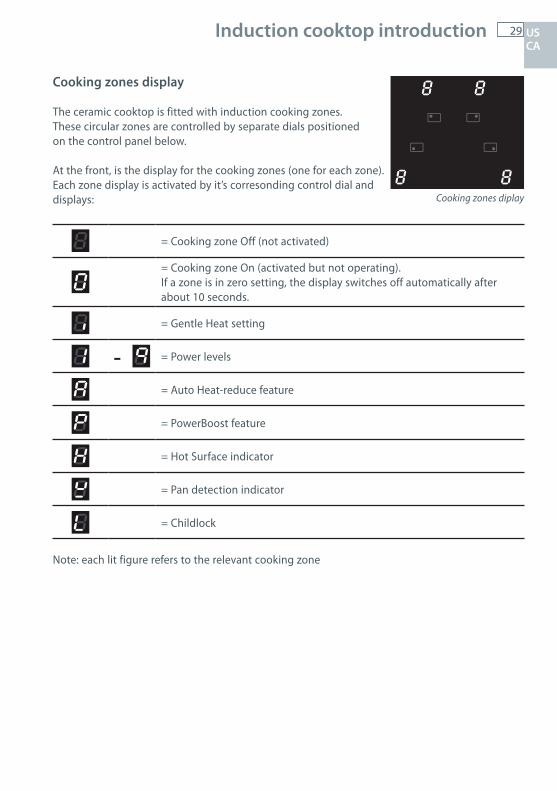
Cooking zones display
The ceramic cooktop is fitted with induction cooking zones.These circular zones are controlled by separate dials positioned on the control panel below.
At the front, is the display for the cooking zones (one for each zone). Each zone display is activated by it’s corresonding control dial and displays:
= Cooking zone Off (not activated)
= Cooking zone On (activated but not operating).If a zone is in zero setting, the display switches off automatically after about 10 seconds.
= Gentle Heat setting
- = Power levels
= Auto Heat-reduce feature
= PowerBoost feature
= Hot Surface indicator
= Pan detection indicator
= Childlock
Note: each lit figure refers to the relevant cooking zone
Cooking zones diplay
US CA
30 Choosing the right cookware
1
1
3
2
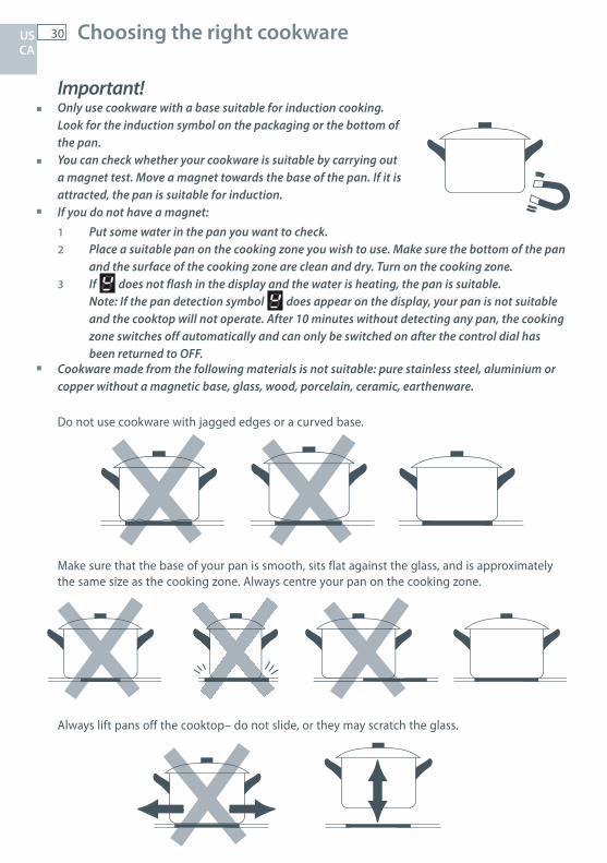
Important! Only use cookware with a base suitable for induction cooking.
Look for the induction symbol on the packaging or the bottom of the pan.
You can check whether your cookware is suitable by carrying out a magnet test. Move a magnet towards the base of the pan. If it is attracted, the pan is suitable for induction.
If you do not have a magnet: 1 Put some water in the pan you want to check. 2 Place a suitable pan on the cooking zone you wish to use. Make sure the bottom of the pan
and the surface of the cooking zone are clean and dry. Turn on the cooking zone. 3 If does not flash in the display and the water is heating, the pan is suitable. Note: If the pan detection symbol does appear on the display, your pan is not suitable and the cooktop will not operate. After 10 minutes without detecting any pan, the cooking
zone switches off automatically and can only be switched on after the control dial has been returned to OFF.
Cookware made from the following materials is not suitable: pure stainless steel, aluminium or copper without a magnetic base, glass, wood, porcelain, ceramic, earthenware.
Do not use cookware with jagged edges or a curved base.
Make sure that the base of your pan is smooth, sits flat against the glass, and is approximately the same size as the cooking zone. Always centre your pan on the cooking zone.
Always lift pans off the cooktop– do not slide, or they may scratch the glass.
US CA
31Choosing the right cookware
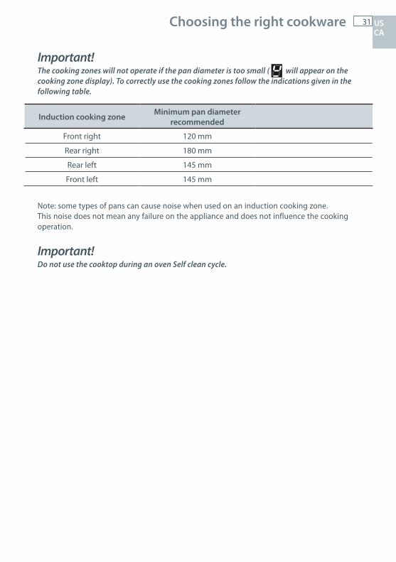
Important!The cooking zones will not operate if the pan diameter is too small ( will appear on the cooking zone display). To correctly use the cooking zones follow the indications given in the following table.
Note: some types of pans can cause noise when used on an induction cooking zone.This noise does not mean any failure on the appliance and does not influence the cooking operation.
Important!Do not use the cooktop during an oven Self clean cycle.
Induction cooking zone Minimum pan diameter recommended
Front right 120 mm
Rear right 180 mm
Rear left 145 mm
Front left 145 mm
US CA
32 Using your induction cooktop
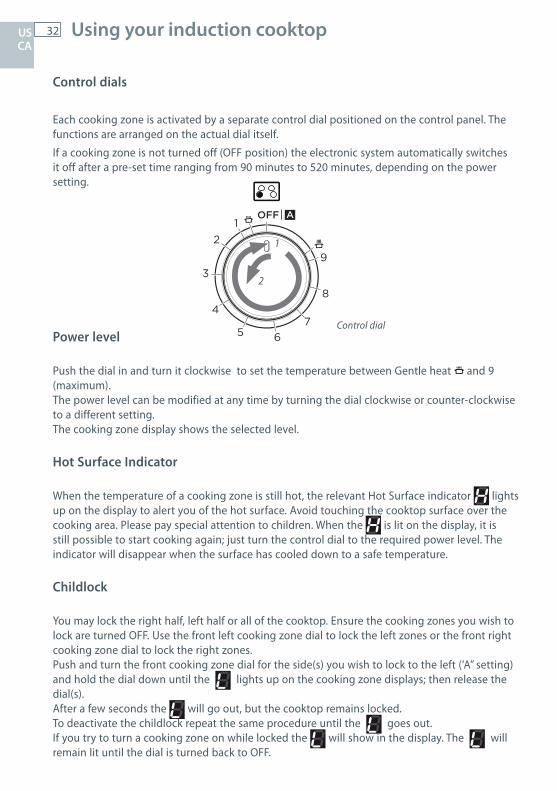
Control dials
Each cooking zone is activated by a separate control dial positioned on the control panel. The functions are arranged on the actual dial itself.
If a cooking zone is not turned off (OFF position) the electronic system automatically switches it off after a pre-set time ranging from 90 minutes to 520 minutes, depending on the power setting.
Power level
Push the dial in and turn it clockwise to set the temperature between Gentle heat
1
2
12
3
4
5 67
8
9
OFF A and 9 (maximum). The power level can be modified at any time by turning the dial clockwise or counter-clockwise to a different setting.The cooking zone display shows the selected level.
Hot Surface Indicator
When the temperature of a cooking zone is still hot, the relevant Hot Surface indicator lights up on the display to alert you of the hot surface. Avoid touching the cooktop surface over the cooking area. Please pay special attention to children. When the is lit on the display, it is still possible to start cooking again; just turn the control dial to the required power level. The indicator will disappear when the surface has cooled down to a safe temperature.
Childlock
You may lock the right half, left half or all of the cooktop. Ensure the cooking zones you wish to lock are turned OFF. Use the front left cooking zone dial to lock the left zones or the front right cooking zone dial to lock the right zones.Push and turn the front cooking zone dial for the side(s) you wish to lock to the left (‘A” setting) and hold the dial down until the lights up on the cooking zone displays; then release the dial(s). After a few seconds the will go out, but the cooktop remains locked. To deactivate the childlock repeat the same procedure until the goes out. If you try to turn a cooking zone on while locked the will show in the display. The will remain lit until the dial is turned back to OFF.
1
2
12
3
4
5 67
8
9
OFF A
Control dial
US CA
33Using your cooktop’s special features
Using the Auto Heat-reduce feature
This feature is available on all the cooking zonesPush and turn the control dial counter-clockwise to the ‘A’ setting until the symbol lights up on the corresponding cooking zone display then release the dial. Within 5 seconds turn the dial to the desired power level (between 1 and 8); once a setting has been selected, after a few seconds will replace the power level on the display.
This feature allows the cooking zone to operate at the maximum power (100%) for a time proportional to the selected power level; after this time the cooking zone will operate at the selected level.While this feature is operating it is possible, at any time, to increase the selected power level up to level 8 (at level 9 the function will be disabled). It is not possible to decrease the power.The Auto Heat-reduce feature can be disabled by turning the dial anti-clockwise to a lower power level, turning the dial to the OFF position or by selecting level 9 or the PowerBoost feature.
Note: If removing the pan from the cooking zone before the programme has been completed, the Auto Heat-reduce feature will be completed with the remaining time if the pan is put back on the cooking zone within 30 seconds, while the and are alternating in the display. After 30 seconds the zone is automatically turned off.
Using the PowerBoost feature
Turn the control dial clockwise to set the maximum power level (9), then turn clockwise again to the setting until ‘P’ appears on the display, then release the dial; the control dial returns to the maximum setting (9) automatically and the symbol lights up on the corresponding cooking zone display. The PowerBoost feature is now on.
This feature allows the cooking zone to operate at the PowerBoost maximum power (above the rated power) for a maximum of 10 minutes; it could be used, for example, to rapidly heat up a large amount of water. After 10 minutes will flash for a few seconds. The cooking zone willthen decrease to power level 9.The PowerBoost feature can be disabled by turning the dial anti-clockwise to a lower power level, turning the dial to the OFF position or by turning the dial again to the setting; in this case the cooking zone operates at the power level 9.
Note: if a cooking zone is still hot, it is not possible to use the PowerBoost feature and will flash if you try to activate. The cooking zone is automatically set to the maximum power level (9).The PowerBoost feature is always limited to a maximum of 10 minutes. You can activate the PowerBoost feature again after 10 minutes.
Important!The PowerBoost feature is not suitable for use with non water based cooking.Do not use this function for heating oil (e.g. deep fat frying). The power density may be too high and it could damage the cookware.
US CA

34 Using your cooktop’s special features
Maximum usable power for the cooking zones
The right and left cooking zones are controlled by twoseparate power boards and the maximum total power pereach power board is 3700 W.Should the cooking zones of one power board require morethan 3700 W, the last selected power level has priority and thepower of the other cooking zone is automatically reduced tothe remaining power available.If this occurs, the cooking zone will display a flashing figurefor about 3 seconds before automatically displaying the newpower level.
This means for example that: When setting PowerBoost for the second zone, the setting for the other zone could be reduced
to the remaining power available. When setting PowerBoost for a zone and then another setting on the second zone, if the total
power exceed 3700 W the PowerBoost feature is automatically turned off and the power reduced to the maximum power available.
Gentle Heat
The Gentle heat setting is ideal for keeping cooked food warm and the gentle warming of delicate foods for up to 2 hours.Push and turn the dial to the
1
2
12
3
4
5 67
8
9
OFF A setting. The display will show .
Thermal protection
The induction cooktop is fitted with safety devices to protect the electronic system and to protect each cooking zone from overheating.In case of overheating, one of the following automatic functions could be started by the electronic system:
PowerBoost feature automatically turned off and power reduced; one or more cooking zone switched off; cooling fan motor of the induction unit switched on.
Controlled by1st power board
Controlled by2nd power board
Controlled by1st power board
Controlled by2nd power board
US CA
35
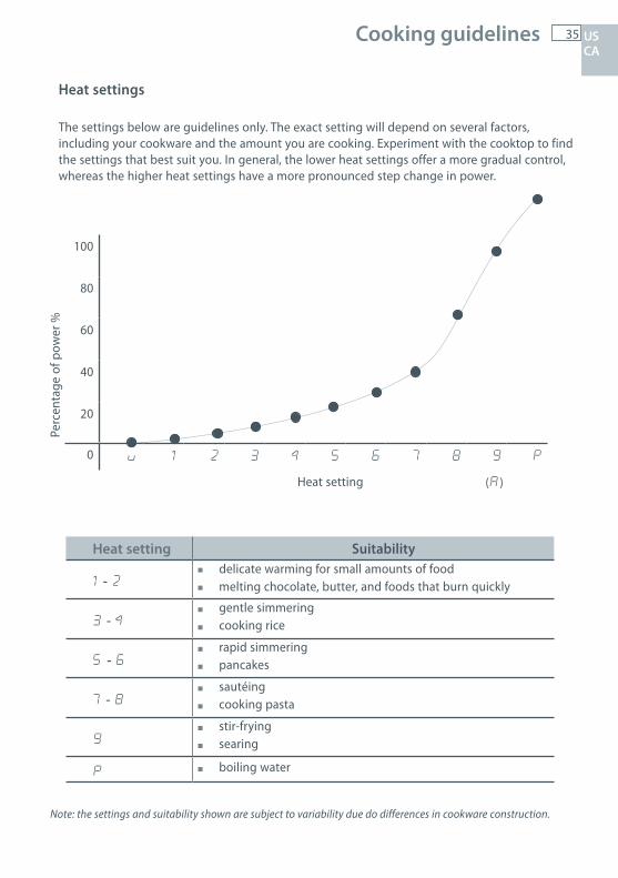
Heat settings
The settings below are guidelines only. The exact setting will depend on several factors, including your cookware and the amount you are cooking. Experiment with the cooktop to find the settings that best suit you. In general, the lower heat settings offer a more gradual control, whereas the higher heat settings have a more pronounced step change in power.
Perc
enta
ge o
f pow
er %
100
80
60
40
20
0 u 1 2 3 4 5 6 7 8 9 P
Heat setting (A)
Heat setting Suitability
1 - 2 delicate warming for small amounts of food melting chocolate, butter, and foods that burn quickly
3 - 4 gentle simmering
cooking rice
5 - 6 rapid simmering
pancakes
7 - 8 sautéing
cooking pasta
9 stir-frying
searing
P boiling water
Cooking guidelines
Note: the settings and suitability shown are subject to variability due do differences in cookware construction.
US CA
36 Using the warming drawerUS CA
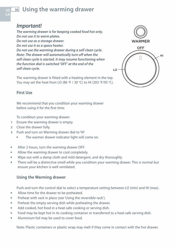
Important! The warming drawer is for keeping cooked food hot only. Do not use it to warm plates.Do not use as a storage drawer.Do not use it as a space heater.Do not use the warming drawer during a self clean cycle.Note: The drawer will automatically turn off when the self clean cycle is started. It may resume functioning when the function dial is switched ‘OFF’ at the end of the self clean cycle.
The warming drawer is fitted with a heating element in the top.You may set the heat from LO (86 oF / 30 oC) to HI (203 oF/95 oC).
First Use
We recommend that you condition your warming drawer before using it for the first time.
To condition your warming drawer:1 Ensure the warming drawer is empty.2 Close the drawer fully.3 Push and turn on Warming drawer dial to ‘HI’
The warmer drawer indicator light will come on.
After 2 hours, turn the warming drawer OFF. Allow the warming drawer to cool completely. Wipe out with a damp cloth and mild detergent, and dry thoroughly. There will be a distinctive smell while you condition your warming drawer. This is normal but
ensure your kitchen is well ventilated.
Using the Warming drawer
Push and turn the control dial to select a temperature setting between LO (min) and HI (max). Allow time for the drawer to be preheated. Preheat with rack in place (see ‘Using the reversible rack’). Preheat the empty serving dish while preheating the drawer. Add cooked, hot food in a heat-safe cooking or serving dish. Food may be kept hot in its cooking container or transferred to a heat-safe serving dish. Aluminium foil may be used to cover food.
Note: Plastic containers or plastic wrap may melt if they come in contact with the hot drawer.
37 Using the warming drawer US CA
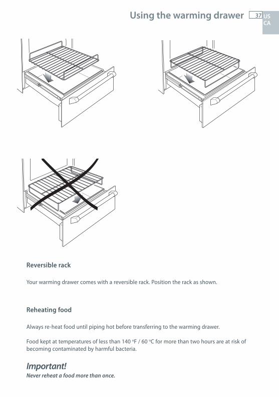
Reversible rack
Your warming drawer comes with a reversible rack. Position the rack as shown.
Reheating food
Always re-heat food until piping hot before transferring to the warming drawer.
Food kept at temperatures of less than 140 oF / 60 oC for more than two hours are at risk of becoming contaminated by harmful bacteria.
Important! Never reheat a food more than once.
38 Care and cleaning
Important!Before you start cleaning your cooker, please:
Read these cleaning instructions and the ‘Safety and warnings’ section at the start of this user guide.
Turn the cooker off at the wall. Make sure the cooker is a safe temperature to touch. Do not use a steam cleaner. Do not store flammable substances in the oven or warming drawer.
General advice
Wipe down the cooktop and wipe out the oven after every use. Wipe up spills. Avoid leaving alkaline or acidic substances (such as lemon juice or vinegar) on
the surfaces. Do not use cleaning products with a chlorine or acidic base (ie citrus-based cleaners).
Cleaning the outside of the cooker
Important! Do not use abrasive cleaners, cloths or pads on the outside surfaces. Immediately wipe off any caustic cleaners if they are spilled onto the oven door handle.
Wipe the outside surfaces often, using warm water and a mild household detergent. The stainless steel may also be cleaned with a suitable cleaner and polish.
Note: if you choose to use a commercial stainless steel cleaner, please read the label to makesure it does not contain chlorine compounds as these are corrosive and may damage theappearance of your cooker.
US CA
39 Care and cleaning
Caring for your cooktop
Important! Some heavy-duty and nylon scourers can scratch the ceramic glass of your cooktop. Always read
the label to check if your scourer is suitable for cleaning ceramic glass cooktops. Use ceramic glass cleaner on the cooktop while it is warm to touch. Rinse and wipe dry with a
clean cloth or paper towel. The cooktop may become stained if cleaning residue remains. Remove any food, spillovers or grease from the cooktop while it is still warm using a razor blade
scraper suitable for ceramic glass surfaces. Do not use knives or any other sharp object for cleaning. Take extra care to avoid damaging the seal at the edges of the ceramic glass surface.
Do not use cleaning products with a chlorine or acidic base.
Metallic stains
Copper-based or aluminium cookware may cause metallic staining. These stains show as ametallic sheen on the cooktop. If the cooktop is not cleaned after every use and the stainsare allowed to burn onto the surface, they may react with the glass and will no longer beremovable. To help prevent such damage, clean the cooktop after every use and apply aglass cooktop conditioner.
Cleaning melts and spillovers
Anything that melts onto the ceramic glass surface or food spills with a high sugar content maycause pitting of the ceramic glass surface if they are left there to cool. Examples include:
plastic wrap melted aluminum foil sugar, sugary syrups, jams and jellies vegetables and vegetable water with a high sugar content eg peas, sweet corn, beetroot.
Remove these spills immediately with a special razor blade cooktop scraper, taking care not to scratch the glass. Follow the steps below:
1 Turn the element off and carefully scrape the spill to a cool area of the cooktop surface.2 Clean the spill up with a cloth or paper towel.3 As soon as the cooktop is cool enough to safely touch, clean with cooktop cleaner.
Cleaning the stainless steel surround strip
To remove fingerprints and other marks, wipe with a clean damp cloth and dry with a lintfree cloth.
US CA
40 Care and cleaning
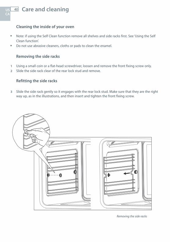
Cleaning the inside of your oven
Note: if using the Self Clean function remove all shelves and side racks first. See ‘Using the Self Clean function’.
Do not use abrasive cleaners, cloths or pads to clean the enamel.
Removing the side racks
1 Using a small coin or a flat-head screwdriver, loosen and remove the front fixing screw only.2 Slide the side rack clear of the rear lock stud and remove.
Refitting the side racks
3 Slide the side rack gently so it engages with the rear lock stud. Make sure that they are the right way up, as in the illustrations, and then insert and tighten the front fixing screw.
Removing the side racks
US CA
41 Care and cleaning US CA
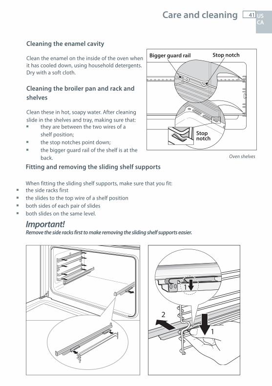
Cleaning the enamel cavity
Clean the enamel on the inside of the oven when it has cooled down, using household detergents. Dry with a soft cloth.
Cleaning the broiler pan and rack and shelves
Clean these in hot, soapy water. After cleaning slide in the shelves and tray, making sure that:
they are between the two wires of a shelf position;
the stop notches point down; the bigger guard rail of the shelf is at the
back. Oven shelves
Fitting and removing the sliding shelf supports
When fitting the sliding shelf supports, make sure that you fit: the side racks first the slides to the top wire of a shelf position both sides of each pair of slides both slides on the same level.
Important!Remove the side racks first to make removing the sliding shelf supports easier.
1
2
1
Bigger guard rail Stop notch
Stopnotch
42US CA
Using the Self Clean function
During the pyrolytic Self Clean cycle the extremely high temperature burns off and breaks down grime and grease deposits. All that is left is a small amount of grey ash that you can easily remove.
You can set the Self Clean cycle time between one and a half and three hours. The heavier the soiling, the longer the cleaning time required.
Important! You must clean the inside glass door panel BEFORE starting a Self Clean cycle. Failure to do this
may result in permanent staining or marking of the door glass.
Do not use oven cleaners, any degreasing cleaners, or oven liners. Make sure you remove the side racks, oven shelves and trays and all other bakeware and utensils
from the oven before starting a Self Clean cycle. If left in the oven, they will become permanently discoloured or damaged; items made from combustible materials (eg wood, fabric, plastic) may even catch fire.
Do not operate the warming drawer during the self clean cycle. The warming drawer will become warm during the Self Clean cycle. Do not store flammable items
in the warming drawer. If possible, avoid opening the drawer during the cycle, or use oven mitts to remove items from the drawer.
Do not use your oven to clean miscellaneous parts. Make sure the room is well ventilated. Before starting a Self Clean cycle, make sure you move any pet birds to another, closed and well-
ventilated room. Some pet birds are extremely sensitive to the fumes given off during a Self Clean cycle, and may die if left in the same room as the oven during such a cycle.
During a Self Clean cycle, the oven reaches higher temperatures than it does for cooking. Under such conditions, the surfaces may get hotter than usual and children should be kept away.
The oven door will be locked during the Self Clean cycle. After the Self Clean cycle has finished, the door will remain locked until the oven has cooled to a safe temperature. This may take up to 30 minutes.
If there are cracks or flaws on any of the oven door glass panes, if the oven seal is damaged or worn, or if the door does not close properly, do not start a Self Clean cycle. Call your Authorised Repairer or Customer Care.
Caution: Do not leave food or cooking utensils etc. in the oven during self-cleaning.
Care and cleaning
43
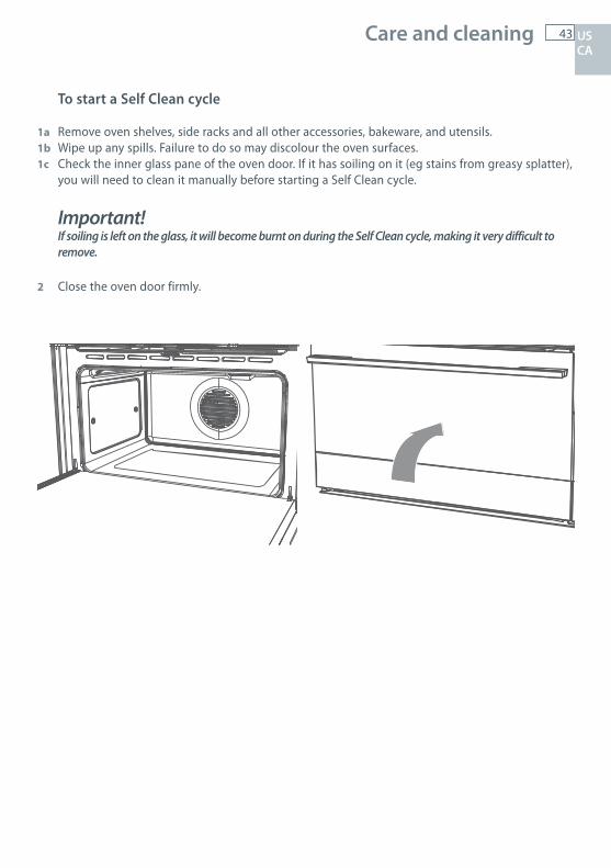
To start a Self Clean cycle
1a Remove oven shelves, side racks and all other accessories, bakeware, and utensils.1b Wipe up any spills. Failure to do so may discolour the oven surfaces. 1c Check the inner glass pane of the oven door. If it has soiling on it (eg stains from greasy splatter),
you will need to clean it manually before starting a Self Clean cycle.
Important!If soiling is left on the glass, it will become burnt on during the Self Clean cycle, making it very difficult to remove.
2 Close the oven door firmly.
US CA
Care and cleaning
44US CA
Care and cleaning
3 Select the Self Clean Function
410 430F FF 190OFF
The display will show The P will flash.
4 Adjust the cycle time (optional) You may set the time between 1-1/2 hours (P1:30 and 3 hours (P3:00). For heavy soiling use
a longer time. Press the
12:00 A
button - the P will go out. Use the
12:00 A
and
12:00 A
buttons or rotate the temperature dial to change the time. After a few seconds the P will start to flash again. Alternatively, press the
12:00 A
button to confirm and the P will flash.
5 Start the cycle Press the
12:00 A
button. The P will stop flashing. The oven will come on and the
12:00 A
indicator will show in the display. After a few seconds the door will lock and the door lock indicator light will come on. The display will start to count down.
Note: If the door is not shut completely, after a few minutes the oven will switch off, the display will show ‘door’ and the oven will beep. See ‘Troubleshooting’.
6 At the end of the Self Clean cycle The oven will turn off. The display will show P:00 and a flashing A
7 Turn the function dial to OFF. The door will remain locked. The door lock indicator will remain on. The display will show ‘hot’.
When the oven has cooled to a safe temperature, the door lock indicator will go out and the door will unlock. The display will show the time of day. This may take 30 minutes.
Note: The oven will still be very warm. To avoid burns, wait for the oven to cool completely before wiping out the ash and replacing side racks and shelves.
To cancel a Self Clean cycleTurn the function dial to OFF.
Note: The oven door will remain locked until the oven has cooled to a safe temperature. The doorlock indicator light will remain on, and the display will show ‘hot’.
We do not recommend that you start a new Self clean cycle before the oven has cooled completely.
P1:30 A
45 Care and cleaning
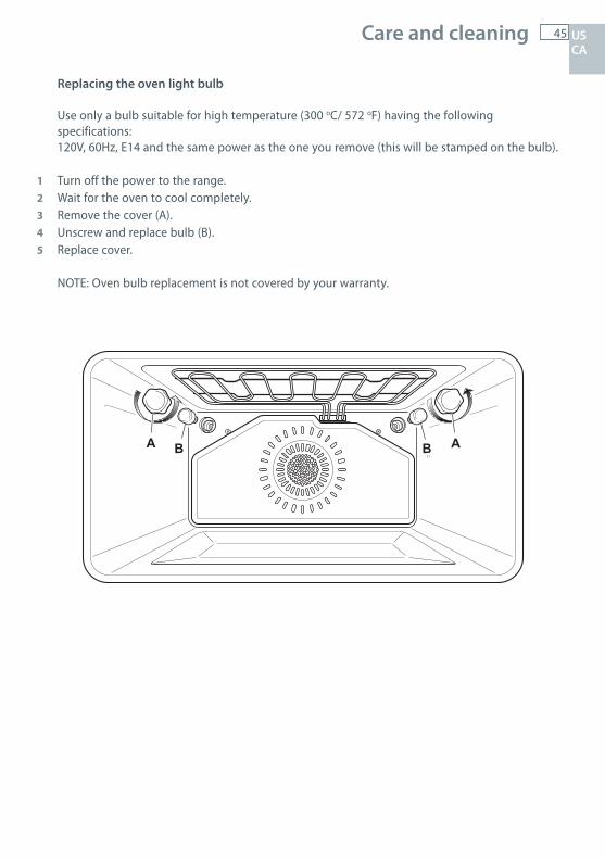
Replacing the oven light bulb
Use only a bulb suitable for high temperature (300 oC/ 572 oF) having the following specifications:120V, 60Hz, E14 and the same power as the one you remove (this will be stamped on the bulb).
1 Turn off the power to the range.2 Wait for the oven to cool completely. 3 Remove the cover (A). 4 Unscrew and replace bulb (B). 5 Replace cover.
NOTE: Oven bulb replacement is not covered by your warranty.
B BA A
US CA
46 Care and cleaning
2
2
3
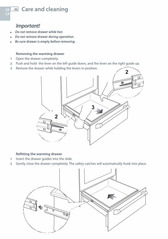
Important! Do not remove drawer while hot. Do not remove drawer during operation. Be sure drawer is empty before removing.
Removing the warming drawer1 Open the drawer completely.2 Push and hold the lever on the left guide down, and the lever on the right guide up.3 Remove the drawer while holding the levers in position.
Refitting the warming drawer1 Insert the drawer guides into the slide.2 Gently close the drawer completely. The safety catches will automatically hook into place.
US CA
47 Care and cleaning
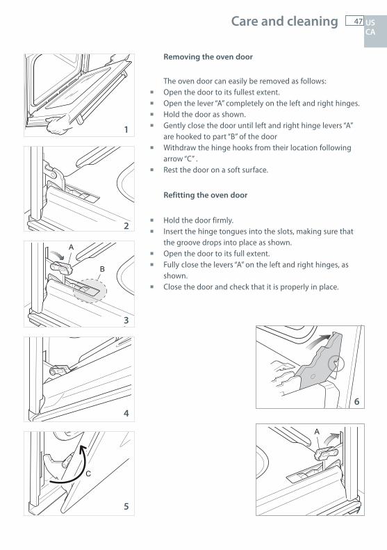
Removing the oven door
The oven door can easily be removed as follows: Open the door to its fullest extent. Open the lever “A” completely on the left and right hinges. Hold the door as shown. Gently close the door until left and right hinge levers “A”
are hooked to part “B” of the door Withdraw the hinge hooks from their location following
arrow “C” . Rest the door on a soft surface.
Refitting the oven door
Hold the door firmly. Insert the hinge tongues into the slots, making sure that
the groove drops into place as shown. Open the door to its full extent. Fully close the levers “A” on the left and right hinges, as
shown. Close the door and check that it is properly in place.
B
A
C
A
1
2
3
4
5
6
7
US CA
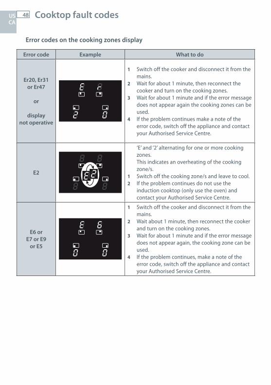
48 Cooktop fault codes
Error codes on the cooking zones display
Error code Example What to do
Er20, Er31 or Er47
or
displaynot operative
1 Switch off the cooker and disconnect it from the mains.
2 Wait for about 1 minute, then reconnect the cooker and turn on the cooking zones.
3 Wait for about 1 minute and if the error message does not appear again the cooking zones can be used.
4 If the problem continues make a note of the error code, switch off the appliance and contact your Authorised Service Centre.
E2
‘E’ and ‘2’ alternating for one or more cooking zones.This indicates an overheating of the cooking zone/s.
1 Switch off the cooking zone/s and leave to cool.2 If the problem continues do not use the
induction cooktop (only use the oven) and contact your Authorised Service Centre.
E6 orE7 or E9
or E5
1 Switch off the cooker and disconnect it from the mains.
2 Wait about 1 minute, then reconnect the cooker and turn on the cooking zones.
3 Wait for about 1 minute and if the error message does not appear again, the cooking zone can be used.
4 If the problem continues, make a note of the error code, switch off the appliance and contact your Authorised Service Centre.
US CA
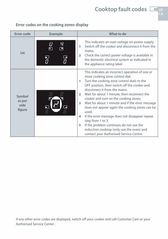
49 Cooktop fault codes
Error codes on the cooking zones display
Error code Example What to do
U4
This indicates an over-voltage on power supply.1 Switch off the cooker and disconnect it from the
mains.2 Check the correct power voltage is available in
the domestic electrical system as indicated in the appliance rating label.
Symbolas perside
figure
This indicates an incorrect operation of one or more cooking zone control dial.
1 Turn the cooking zone control dials to the OFF position, then switch off the cooker and disconnect it from the mains.
2 Wait for about 1 minute, then reconnect the cooker and turn on the cooking zones.
3 Wait for about 1 minute and if the error message does not appear again the cooking zones can be used.
4 If the error message does not disappear repeat step from 1 to 3.
5 If the problem continues do not use the induction cooktop (only use the oven) and contact your Authorised Service Centre.
If any other error codes are displayed, switch off your cooker and call Customer Care or your Authorised Service Center .
US CA
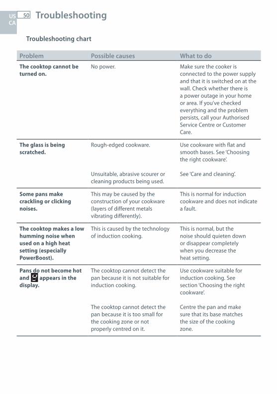
50 Troubleshooting
Troubleshooting chart
Problem Possible causes What to do
The cooktop cannot beturned on.
No power. Make sure the cooker is connected to the power supply and that it is switched on at the wall. Check whether there is a power outage in your home or area. If you’ve checked everything and the problem persists, call your Authorised Service Centre or Customer Care.
The glass is beingscratched.
Rough-edged cookware.
Unsuitable, abrasive scourer or cleaning products being used.
Use cookware with flat and smooth bases. See ‘Choosing the right cookware’.
See ‘Care and cleaning’.
Some pans make crackling or clicking noises.
This may be caused by theconstruction of your cookware (layers of different metals vibrating differently).
This is normal for induction cookware and does not indicate a fault.
The cooktop makes a lowhumming noise when used on a high heat setting (especially PowerBoost).
This is caused by the technology of induction cooking.
This is normal, but thenoise should quieten downor disappear completelywhen you decrease theheat setting.
Pans do not become hot and appears in the display.
The cooktop cannot detect the pan because it is not suitable forinduction cooking.
The cooktop cannot detect the pan because it is too small forthe cooking zone or notproperly centred on it.
Use cookware suitable forinduction cooking. Seesection ‘Choosing the rightcookware’.
Centre the pan and makesure that its base matchesthe size of the cookingzone.
US CA
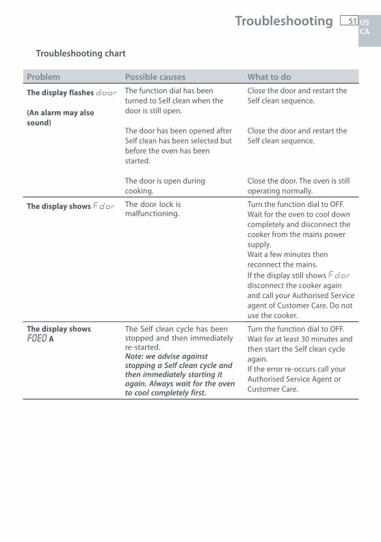
51 Troubleshooting
Troubleshooting chart
US CA
Problem Possible causes What to do
The display flashes door
(An alarm may also sound)
The function dial has beenturned to Self clean when thedoor is still open.
The door has been opened afterSelf clean has been selected butbefore the oven has beenstarted.
The door is open duringcooking.
Close the door and restart theSelf clean sequence.
Close the door and restart theSelf clean sequence.
Close the door. The oven is stilloperating normally.
The display shows Fdor The door lock ismalfunctioning.
Turn the function dial to OFF.Wait for the oven to cool downcompletely and disconnect thecooker from the mains powersupply.Wait a few minutes thenreconnect the mains.If the display still shows Fdordisconnect the cooker again and call your Authorised Service agent of Customer Care. Do not use the cooker.
The display shows F0E0 A
The Self clean cycle has beenstopped and then immediatelyre-started.Note: we advise againststopping a Self clean cycle andthen immediately starting itagain. Always wait for the ovento cool completely first.
Turn the function dial to OFF.Wait for at least 30 minutes andthen start the Self clean cycleagain.If the error re-occurs call yourAuthorised Service Agent orCustomer Care.
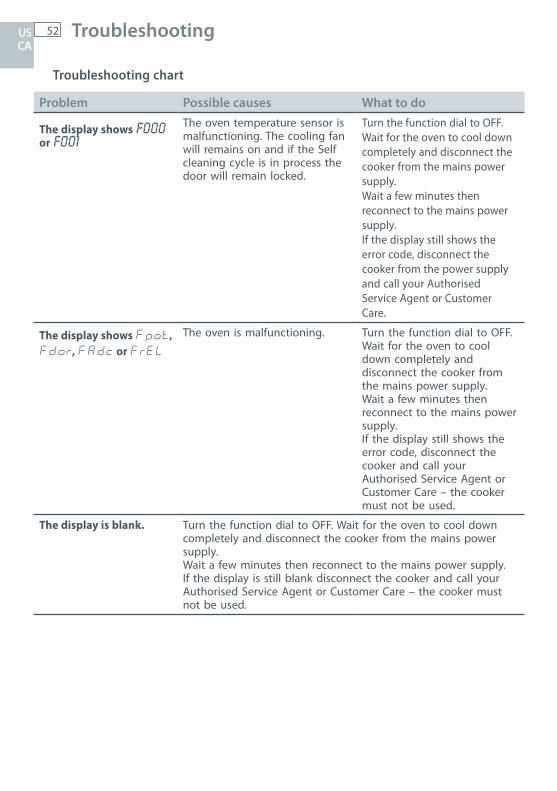
52 Troubleshooting
Troubleshooting chart
Problem Possible causes What to do
The display shows F000 or F001
The oven temperature sensor ismalfunctioning. The cooling fanwill remains on and if the Selfcleaning cycle is in process thedoor will remain locked.
Turn the function dial to OFF.Wait for the oven to cool downcompletely and disconnect thecooker from the mains powersupply.Wait a few minutes thenreconnect to the mains powersupply.If the display still shows theerror code, disconnect thecooker from the power supplyand call your AuthorisedService Agent or CustomerCare.
The display shows Fpot,Fdor, FAdc or FrEL
The oven is malfunctioning. Turn the function dial to OFF.Wait for the oven to cool down completely and disconnect the cooker from the mains power supply.Wait a few minutes thenreconnect to the mains powersupply.If the display still shows theerror code, disconnect thecooker and call your Authorised Service Agent or Customer Care – the cooker must not be used.
The display is blank. Turn the function dial to OFF. Wait for the oven to cool downcompletely and disconnect the cooker from the mains powersupply.Wait a few minutes then reconnect to the mains power supply.If the display is still blank disconnect the cooker and call your Authorised Service Agent or Customer Care – the cooker must not be used.
US CA

53 Warranty and service US CA
Before you call for service or assistance ...
Check the things you can do yourself. Refer to the installation instructions and your user guide and check that:
1 your product is correctly installed2 you are familiar with its normal operation.
If after checking these points you still need assistance or parts, please refer to the Service & Warranty book for warranty details and your nearest Authorized Service Center, or contact us through our local website listed on the back cover.
Product details
Fisher & Paykel Ltd
Model Serial no.
Date of purchase Purchaser
Dealer Suburb
Town Country


US CA 07.2015F&P PN - 590619 C F&P ITALY PN - 1104411 - B3
www.fisherpaykel.com
Copyright © Fisher & Paykel 2015. All rights reserved.The product specifications in this booklet apply to the specific products and models described at the date of issue. Under our policy of continuous product improvement, these specifications may change at any time. You should therefore check with your Dealer to ensure this booklet correctly describes the product currently available.