Embed Size (px)
Citation preview
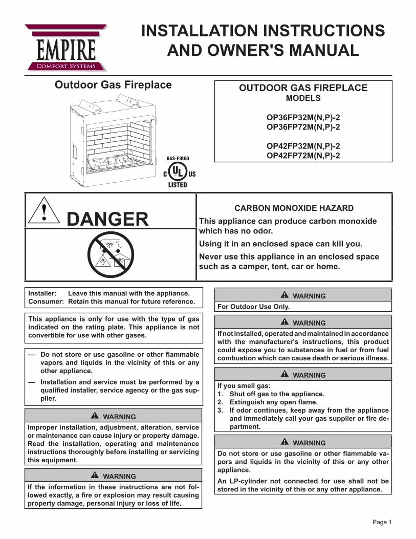
INSTALLATION INSTRUCTIONSAND OWNER'S MANUAL
OUTDOOR GAS FIREpLACEMODELS
Op36Fp32M(N,p)-2Op36Fp72M(N,p)-2
Op42Fp32M(N,p)-2Op42Fp72M(N,p)-2
Outdoor Gas Fireplace
EMPIREEMPIREComfort Systems
! DANGERCARBON MONOXIDE HAZARD
This appliance can produce carbon monoxide which has no odor.Using it in an enclosed space can kill you.Never use this appliance in an enclosed space such as a camper, tent, car or home.
GAS-FIRED
Installer: Leave this manual with the appliance.Consumer: Retain this manual for future reference.
This appliance is only for use with the type of gas indicated on the rating plate. This appliance is not convertible for use with other gases.
— Donotstoreorusegasolineorotherflammablevapors and liquids in the vicinity of this or any other appliance.
— Installation and service must be performed by a qualifiedinstaller,serviceagencyorthegassup-plier.
WARNINGImproper installation, adjustment, alteration, service or maintenance can cause injury or property damage. Read the installation, operating and maintenance instructions thoroughly before installing or servicing this equipment.
WARNINGIf the information in these instructions are not fol-lowedexactly,afireorexplosionmayresultcausingproperty damage, personal injury or loss of life.
WARNINGFor Outdoor Use Only.
WARNINGIf not installed, operated and maintained in accordance with the manufacturer's instructions, this product could expose you to substances in fuel or from fuel combustion which can cause death or serious illness.
WARNINGIf you smell gas:1. Shut off gas to the appliance.2. Extinguishanyopenflame.3. If odor continues, keep away from the appliance
andimmediatelycallyourgassupplierorfirede-partment.
WARNINGDonotstoreorusegasolineorotherflammableva-pors and liquids in the vicinity of this or any other appliance.An Lp-cylinder not connected for use shall not be stored in the vicinity of this or any other appliance.
Page 1

32272-7-0115Page 2
SECTION PAGEImportant Safety Information ....................................................................................3Safety Information for Users of LP-Gas ...................................................................4Introduction ...........................................................................................................5-6Specifications ...........................................................................................................7Gas Supply ...............................................................................................................8Clearances ...............................................................................................................8Combustible Materials ..............................................................................................9Fireplace Dimensions ........................................................................................10-11Planning Installation ..........................................................................................11-12Fireplace Framing and Installation .........................................................................13Gas Line Connection ..............................................................................................13Operation Instructions / Flame Appearance ...........................................................13OP(36,42)FP72 Lighting Instructions .....................................................................14OP(36,42)FP32 Lighting Instructions .....................................................................15Pilot and Main Burner Flame Characteristics .........................................................16Wiring Diagrams ................................................................................................16-17Remote Control Installation & Operation ................................................................18Maintenance ...........................................................................................................19Troubleshooting ......................................................................................................19Parts List ...........................................................................................................20-21Parts View ..............................................................................................................22Master Parts Distributor List ...................................................................................23How To Order Repair Parts ....................................................................................23Warranty Terms ......................................................................................................24
TABLE OF CONTENTS
32272-7-0115 Page 3
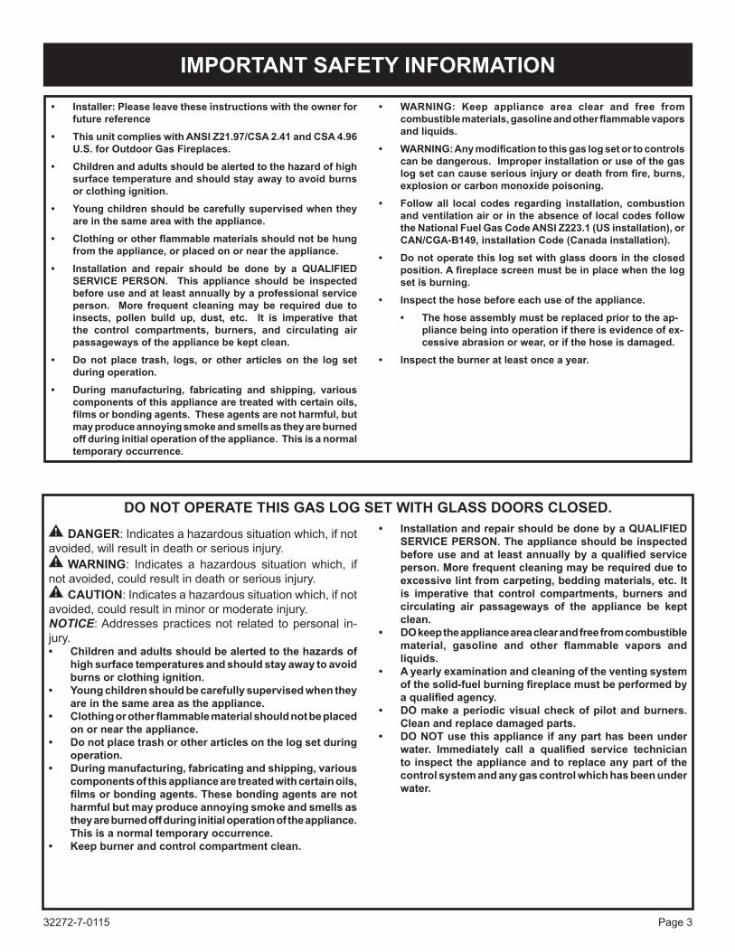
• Installer: please leave these instructions with the owner for future reference
• This unit complies with ANSI Z21.97/CSA 2.41 and CSA 4.96 U.S. for Outdoor Gas Fireplaces.
• Children and adults should be alerted to the hazard of high surface temperature and should stay away to avoid burns or clothing ignition.
• Young children should be carefully supervised when they are in the same area with the appliance.
• Clothingorotherflammablematerialsshouldnotbehungfrom the appliance, or placed on or near the appliance.
• Installation and repair should be done by a QUALIFIED SERVICE pERSON. This appliance should be inspected before use and at least annually by a professional service person. More frequent cleaning may be required due to insects, pollen build up, dust, etc. It is imperative that the control compartments, burners, and circulating air passageways of the appliance be kept clean.
• Do not place trash, logs, or other articles on the log set during operation.
• During manufacturing, fabricating and shipping, various components of this appliance are treated with certain oils, filmsorbondingagents.Theseagentsarenotharmful,butmay produce annoying smoke and smells as they are burned off during initial operation of the appliance. This is a normal temporary occurrence.
• WARNING: Keep appliance area clear and free from combustiblematerials,gasolineandotherflammablevaporsand liquids.
• WARNING:Anymodificationtothisgaslogsetortocontrolscan be dangerous. Improper installation or use of the gas logsetcancauseseriousinjuryordeathfromfire,burns,explosion or carbon monoxide poisoning.
• Follow all local codes regarding installation, combustion and ventilation air or in the absence of local codes follow the National Fuel Gas Code ANSI Z223.1 (US installation), or CAN/CGA-B149, installation Code (Canada installation).
• Do not operate this log set with glass doors in the closed position.Afireplacescreenmustbeinplacewhenthelogset is burning.
• Inspect the hose before each use of the appliance. • The hose assembly must be replaced prior to the ap-
pliance being into operation if there is evidence of ex-cessive abrasion or wear, or if the hose is damaged.
• Inspect the burner at least once a year.
IMpORTANT SAFETY INFORMATION
DO NOT OpERATE THIS GAS LOG SET WITH GLASS DOORS CLOSED.
DANGER: Indicates a hazardous situation which, if not avoided, will result in death or serious injury.
WARNING: Indicates a hazardous situation which, if not avoided, could result in death or serious injury.
CAUTION: Indicates a hazardous situation which, if not avoided, could result in minor or moderate injury.NOTICE: Addresses practices not related to personal in-jury.• Childrenandadultsshouldbealertedtothehazardsof
high surface temperatures and should stay away to avoid burns or clothing ignition.
• Youngchildrenshouldbecarefullysupervisedwhentheyare in the same area as the appliance.
• Clothingorotherflammablematerialshouldnotbeplacedon or near the appliance.
• Donotplacetrashorotherarticlesonthelogsetduringoperation.
• Duringmanufacturing,fabricatingandshipping,variouscomponents of this appliance are treated with certain oils, filmsorbondingagents.Thesebondingagentsarenotharmful but may produce annoying smoke and smells as they are burned off during initial operation of the appliance. This is a normal temporary occurrence.
• Keepburnerandcontrolcompartmentclean.
• Installation and repair should be done by a QUALIFIED SERVICE pERSON. The appliance should be inspected beforeuseandat leastannuallybyaqualifiedserviceperson. More frequent cleaning may be required due to excessive lint from carpeting, bedding materials, etc. It is imperative that control compartments, burners and circulating air passageways of the appliance be kept clean.
• Do keep the appliance area clear and free from combustible material, gasoline and other flammable vapors andliquids.
• A yearly examination and cleaning of the venting system ofthesolid-fuelburningfireplacemustbeperformedbyaqualifiedagency.
• Domake a periodic visual check of pilot and burners. Clean and replace damaged parts.
• DoNoTuse this appliance if any part has been under water. Immediately call a qualified service technicianto inspect the appliance and to replace any part of the control system and any gas control which has been under water.

32272-7-0115Page 4
SAFETY INFORMATION FOR USERS OF Lp-GASPropane(LP-Gas)isaflammablegaswhichcancausefiresand explosions. In its natural state, propane is odorless and colorless. You may not know all the following safety precautions which can protect both you and your family from an accident. Read them carefully now, then review them point by point with the members of your household. Someday when there may not be a minute to lose, everyone’s safety will depend on knowing exactly what to do. If, after reading the following information, you feel you still need more information, please contact your gas supplier.
Lp-GAS WARNING ODOR
If a gas leak happens, you should be able to smell the gas because of the odorant put in the Lp-Gas.
That's your signal to go into immediate action!
• Donotoperateelectricswitches,lightmatches,useyourphone.Do not do anything that could ignite the gas.
• Geteveryoneoutofthebuilding,vehicle,trailer,orarea.Dothat IMMEDIATELY.
• Closeallgastankorcylindersupplyvalves.
• LP-Gasisheavierthanairandmaysettleinlowareassuchasbasements.Whenyouhavereasontosuspectagasleak,keepoutofbasementsandother lowareas. Stayoutuntilfirefightersdeclarethemtobesafe.
• Useyourneighbor’sphoneandcallatrainedLP-Gasservicepersonand thefiredepartment. Even thoughyoumaynotcontinue to smell gas, do not turn on the gas again. Do not re-enter the building, vehicle, trailer, or area.
• Finally, lettheservicemanandfirefighterscheckforescapedgas. Have them air out the area before you return. Properly trained LP-Gas service people should repair the leak, thencheckandrelightthegasapplianceforyou.
NO ODOR DETECTED - ODOR FADESome people cannot smell well. Some people cannot smell theodorofthechemicalputintothegas.Youmustfindoutifyou can smell the odorant in propane.Smokingcandecreaseyour ability to smell. Being around an odor for a time can affect your sensitivity or ability to detect that odor. Sometimes other odors in theareamaskthegasodor.Peoplemaynotsmellthegasodorortheirmindsareonsomethingelse.Thinkingaboutsmellingagasodorcanmakeiteasiertosmell.
The odorant in Lp-gas is colorless, and it can fade under some circumstances. Forexample,ifthereisanundergroundleak,themovementofthegasthroughsoilcanfiltertheodorant.OdorantsinLP-Gas also are subject to oxidation. This fading can occur if there isrustinsidethestoragetankorinirongaspipes.
The odorant in escaped gas can adsorb or absorb onto or into walls, masonry and other materials and fabrics in a room. That will takesomeoftheodorantoutofthegas,reducingitsodorintensity.
LP-Gas may stratify in a closed area, and the odor intensity could vary at different levels. Since it is heavier than air, there may be more odor at lower levels. Always be sensitive to the slightest gas odor.Ifyoudetectanyodor,treatitasaseriousleak.Immediatelygo into action as instructed earlier.
SOME pOINTS TO REMEMBER• Learn to recognize the odor of LP-gas. Your local LP-Gas
Dealer can give you a “Scratch and Sniff” pamphlet. Use it to findoutwhatthepropaneodorsmellslike.IfyoususpectthatyourLP-Gashasaweakorabnormalodor,callyourLP-GasDealer.
• Ifyouarenotqualified,donotlightpilotlights,performservice,ormakeadjustmentstoappliancesontheLP-Gassystem.Ifyouarequalified,consciouslythinkabouttheodorofLP-Gasprior to and while lighting pilot lights or performing service or makingadjustments.
• Sometimesabasementor a closed-uphousehasamustysmell that can cover up the LP-Gas odor. Do not try to light pilotlights,performservice,ormakeadjustmentsinanareawhere the conditions are such that you may not detect the odor iftherehasbeenaleakofLP-Gas.
• Odorfade,duetooxidationbyrustoradsorptiononwallsofnewcylindersandtanks,ispossible.Therefore,peopleshouldbeparticularlyalertandcarefulwhennewtanksorcylindersareplacedinservice.Odorfadecanoccurinnewtanks,orreinstalledoldtanks,iftheyarefilledandallowedtosettoolongbeforerefilling.Cylindersandtankswhichhavebeenoutof service for a time may develop internal rust which will cause odor fade. If such conditions are suspected to exist, a periodic sniff test of the gas is advisable. If you have any question about the gas odor, call your Lp-gas dealer. A periodic sniff test of the Lp-gas is a good safety measure under any condition.
• If,atanytime,youdonotsmelltheLP-Gasodorantandyouthinkyoushould,assumeyouhavealeak.Thentakethesameimmediate action recommended above for the occasion when you do detect the odorized LP-Gas.
• Ifyouexperienceacomplete“gasout,”(thecontainerisundernovaporpressure),turnthetankvalveoffimmediately.Ifthecontainer valve is left on, the container may draw in some air throughopeningssuchaspilotlightorifices.Ifthisoccurs,somenew internal rusting could occur. If the valve is left open, then treatthecontainerasanewtank.Alwaysbesureyourcon-tainer is under vapor pressure by turning it off at the container beforeitgoescompletelyemptyorhavingitrefilledbeforeitiscompletely empty.

32272-7-0115 Page 5
Hearthsshouldslopeawayfromthefrontofthefireplaceandchaseat 1/8 in to 1/4 in per foot. Metal safety strips must be on top of any combustible hearth materials used for moisture management.Whenpurchasingafireboxorfireplacewerecommendyoualsobuy a weather cover or glass door accessory to protect the unit from moisture. Never install a burner where moisture cannot drain off easily. We recommend a weather barrier - such as a cover or bifold glass doors - to protect the burner from moisture.
Screened porch InstallationThefireplacemaybeinstalledsafelyandisdesigncertifiedbyULto be installed in a screen porch with the following guidelines.MinimumPorchArea 96sq.feet(9sqm)Minimum Ceiling Height 92" (234 cm)(See Page 10)
Installation on Rugs and TileIf this appliance is installed directly on carpeting, tile or other combustiblematerialotherthanwoodflooringtheapplianceshallbe installed on a metal or wood panel extending the full width and depth of the appliance. Thebasereferredtoabovedoesnotmeanthefire-proofbaseasused on wood stoves. The protection is for rugs that are extremely thickandlightcoloredtile.
Solid-fuels shall not be burned in a masonry or UL 127 factory-builtfireplaceinwhichanunventedroomheaterisinstalled.
QualifiedInstallingAgencyInstallationandreplacementofgaspiping,gasutilizationequipmentor accessories and repair and servicing of equipment shall beperformedonlybyaqualifiedagency.Theterm"qualifiedagency"meansanyindividual,firm,corporationorcompanywhicheitherinperson or through a representative is engaged in and is responsible for (a) the installation or replacement of gas piping or (b) the connection, installation,repairorservicingofequipment,whoisexperiencedinsuchwork,familiarwithallprecautionsrequiredandhascompliedwithalltherequirementsoftheauthorityhavingjurisdiction.
State of Massachusetts: The installation must be made by a licensed plumber or gas fitter in the Commonwealth ofMassachusetts.
The installation must conform with local codes or, in the absence of local codes, with the National Fuel Gas Code, ANSI Z223.1.**Available from the American National Standards Institute, Inc. 1430 Broadway, New York, N.Y. 10018.High AltitudesFor altitudes/elevations above 2,000 feet (610m), ratings should be reduced at the rate of 4 percent for each 1,000 feet (305m) above sea level. Contact the manufacturer or your gas company before changingspud/orificesize.
Well Head Gas InstallationsSome natural gas utilities use "well head" gas. This may affect the Btu output of the unit. Contact the gas company for the heating value. Contact the manufacturer or your gas company before changing spud/orificesize.
WARNING:Thisapplianceisequippedfor(naturalgasorpropane)gas. Field conversion is not permitted.
Instructions to Installer1. Installer must leave instruction manual with owner after
installation.2. Installermusthaveownerfilloutandmailwarrantycardsupplied
withthisfireplace.3. Installer should show owner how to start and operate unvented
room heater.Always consult your local Building Department regarding regulations, codes or ordinances which apply to the installation of an unvented room heater.*Aftermarket: Completionofsale,notforpurposeofresale,from
the manufacturer.This appliance is only for use with the type of gas indicated on the rating plate. This appliance is not convertible for use with other gases.
WARNINGANY CHANGE TO THIS APPLIANCE OR ITS CONTROLS CAN BE DANGEROUS. Improper installation or use of the appliance can cause se-riousinjuryordeathfromfire,burns,explosionorcarbonmonoxide poisoning.
ThisseriesisdesigncertifiedinaccordancewithAmericanNationalStandard Z21.97.1/CSA 2.41 by the Underwriters Laboratories as an Outdoor Gas Fireplace and should be installed according to these instructions.
Any alteration of the original design, installed other than as shown in these instructions or use with a type of gas not shown on the rating plate is the responsibility of the person and company making the change.
750 Millivolt SystemWhen you ignite the pilot, the thermocouple produces millivolts (electrical current) which energizes the magnet in the gas valve. After 30 seconds to 1 minute time period you can release the gas controlknobandthepilotwillstayON.Allowyourpilotflametooperate an additional one (1) to two (2) minutes before you turn the gascontrolknobfromthePILOTpositiontotheONposition.Thistime period allows the millivolts (electrical energy) to build-up to a sufficientlevelallowingthegascontroltooperateproperly.
ImportantAll correspondence should refer to complete Model Number, Serial Number and type of gas.Moisture ResistanceThisoutdoorfireplacewillshedmoderateamountsofwater,butisnot waterproof. Water and condensing water vapor may enter the chase under certain conditions.Thefireplacewillnotperformasanexteriorwall.Moisturepenetrationmust be considered for construction that places the fireplace instructure walls or on moisture sensitive surfaces.When installed on exterior walls: Empire Comfort Systems recommends the fireplace chase be constructed outside thestructure's weather envelope. Where the platform meets the wall, use aflashingdetailsimilartothatrequiredforattacheddecks.Chaseplatforms, including hearths should slope away from the structure at1/4inperfoot.Thefireplacecanbeshimmedlevel.When installed on surfaces where water may collect or cause damage: Empire Comfort Systems recommends a slope of 1/8 in to1/4inperfoottowardsthedrainportsuggested.Thefireplacecan be shimmed level.
INTRODUCTION
32272-7-0115Page 6
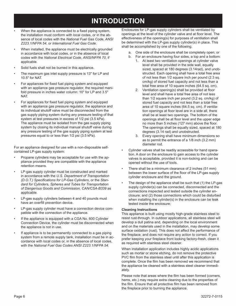
INTRODUCTION• Whentheapplianceisconnectedtoafixedpipingsystem,
the installation must conform with local codes, or in the ab-sence of local codes with the National Fuel Gas Code, ANSI Z223.1/NFPA 54, or International Fuel Gas Code.
• When installed, the appliance must be electrically grounded in accordance with local codes, or in the absence of local codes with the National Electrical Code, ANSI/NFPA 70, if applicable.
• Solid fuels shall not be burned in this appliance.
• The maximum gas inlet supply pressure is 13" for LP and 10.5" for NAT.
• Forappliancesforfixedfuelpipingsystemandequippedwithanappliancegaspressureregulator,therequiredmani-fold pressure in inches water column: 10" for LP and 3.5" NAT.
• Forappliancesforfixedfuelpipingsystemandequippedwith an appliance gas pressure regulator, the appliance and its individual shutoff valve must be disconnected from the gas supply piping system during any pressure testing of that systemattestpressuresinexcessof1/2psi(3.5kPa). The appliance must be isolated from the gas supply piping system by closing its individual manual shutoff valve during any pressure testing of the gas supply piping system at test pressuresequaltoorlessthan1/2psi(3.5kPa).
For an appliance designed for use with a non-disposable self-contained LP-gas supply system:
• Propane cylinders may be acceptable for use with the ap-pliance provided they are compatible with the appliance retention means.
• LP-gassupplycylindermustbeconstructedandmarkedin accordance with the U.S. Department of Transportation (D.O.T.) Specifications for LP-Gas Cylinders, or the Stan-dard for Cylinders, Spheres and Tubes for Transportation of Dangerous Goods and Commission, CAN/CSA-B339 as applicable.
• LP-gas supply cylinders between 4 and 40 pounds must haveanoverfillpreventiondevice.
• LP-gas supply cylinder must have a connection device com-patible with the connection of the appliance.
• IftheapplianceisequippedwithaCGANo.600CylinderConnection Device, the cylinder must be disconnected when the appliance is not in use.
• If appliance is to be permanently connected to a gas piping systemfromaremotesupplytank,installationmustbeinac-cordance with local codes or, in the absence of local codes, with the National Fuel Gas Codes ANSI Z223.1/NFPA 54.
Enclosures for LP-gas supply cylinders shall be ventilated by openingsatthelevelofthecylindervalveandatfloorlevel.Theeffectiveness of the opening(s) for purposes of ventilation shall be determined with the LP-gas supply cylinder(s) in place. This shall be accomplished by one of the following.
a. One side of the enclosure shall be completely open; orb. For an enclosure having four sides, a top and a bottom:
1. At least two ventilation openings at cylinder valve levelshallbeprovidedinthesidewall,equallysized, spaced at 180 degrees (3.14rad), and unob-structed. Each opening shall have a total free area ofnotlessthan1/2squareinchperpound(2.3sq.cm/kg)ofstoredfuelcapacityandnotlessthanatotalfreeareaof10squareinches(64.5sq.cm).
2. Ventilationopening(s)shallbeprovidedatfloorlevel and shall have a total free area of not less than1/2squareinchperpound(3.2sq.cm/kg)ofstored fuel capacity and not less than a total free areaof10squareinches(64.5sq.cm).Ifventila-tionopeningsatfloorlevelareinasideall,thereshall be at least two openings. The bottom of the openingsshallbeatfloorlevelandtheupperedgenomorethan5inches(127mm)abovethefloor.Theopeningsshallbeequallysized,spacedat180degrees (3.14 rad) and unobstructed.
3. Every opening shall have minimum dimensions so as to permit the entrance of a 1/8 inch (3.2 mm) diameter rod.
• Cylinder valves shall be readily accessible for hand opera-tion. A door on the enclosure to gain access to the cylinder valvesisacceptable,provideditisnon-lockingandcanbeopened without the use of tools.
• There shall be a minimum clearance of 2 inches (51 mm) betweenthelowersurfaceoftheflooroftheLP-gassupplycylinder enclosure and the ground.
• The design of the appliance shall be such that (1) the LP-gas supply cylinder(s) can be connected, disconnected and the connections inspected and tested outside the cylinder en-closure; and (2) those connections which could be disturbed wheninstallingthecylinder(s)intheenclosurecanbeleaktested inside the enclosure;
Cleaning InstructionsThis appliance is built using mostly high-grade stainless steel to resist rust-through. In outdoor applications, all stainless steel will develop a dull patina and, depending on the local environment and on the materials used in the installation, may develop some surface oxidation (rust). This does not affect the performance of thefireplace,anddoesnotrequireanyactiontocorrect.Ifyoupreferkeepingyourfireplacefrontlookingfactory-fresh,cleanitasrequiredwithstainlesssteelcleaner.
When installation application includes highly acidic applications such as mortar or stone etching, do not remove the protective PVCfilmfromthestainlesssteeluntilafterthisapplicationiscomplete.Oncethefilmhasbeenremovedwerecommendthatthe appliance be cleaned with a stainless steel cleaner immedi-ately.
Pleasenotethatareaswherethefilmhasbeenformed(corners,hems,etc.)mayrequireextracleaningduetothepropertiesofthefilm.Ensurethatallprotectivefilmhasbeenremovedfromthefireplacepriortoburningtheappliance.

32272-7-0115 Page 7
Model Op36Fp Op42FpInput Btu/h Maximum 50,000 50,000Input Btu/h Minimum - 30 Series 36,000 LP / 38,000 NAT 36,000 LP / 38,000 NATInput Btu/h Minimum - 70 Series 34,000 LP / 32,000 NAT 34,000 LP / 32,000 NATOrifice P276 #45 LP / P280 #29 NAT P276 #45 LP / P280 #29 NATAir Shutter Opening LP FULL OPEN / NAT 1/8" Open LP Full Open / NAT 1/8" Open
AccessoriesBD36SS 36" Bifold Glass Door - Stainless SteelBD42SS 42" Bifold Glass Door - Stainless SteelDT36SS 36" Drain Tray - Stainless SteelDT42SS 42" Drain Tray - Stainless SteelWD36SS 36" Weather Door - Stainless SteelWD42SS 42" Weather Door - Stainless Steel
SpECIFICATIONS
Checkalllocalcodesforrequirements,especiallyforthesizeandtypeofgassupplylinerequired.
Recommended Gas pipe DiameterPipe Length Schedule 40 Pipe
Inside DiameterTubing, Type L
Outside DiameterNat. L.P. Nat. L.P.
0-10 feet0-3 meters
1/2”12.7mm
3/8”9.5mm
1/2”12.7mm
3/8”9.5mm
10-40 feet4-12 meters
1/2”12.7mm
1/2”12.7mm
5/8”15.9mm
1/2”12.7mm
40-100 feet13-30 meters
1/2”12.7mm
1/2”12.7mm
3/4”19mm
1/2”12.7mm
100-150 feet31-46 meters
3/4”19mm
1/2”12.7mm
7/8”22.2mm
3/4”19mm
Note:Neveruseplasticpipe.Checktoconfirmwhetheryourlocalcodes allow copper tubing or galvanized.Note: Since some municipalities have additional local codes, it is always best to consult your local authority and installation code.Note: Be sure to install gas line cover to appliance prior to completing gas line connection.
Installing a New Main Gas Cock Eachapplianceshouldhaveitsownmanualgascock.Amanualmaingascockshouldbelocatedinthevicinityoftheunit.Wherenoneexists,orwhereitssizeorlocationisnotadequate,contact your local authorized installer for installation or relocation.
Compounds used on threaded joints of gas piping shall be resistant totheactionofliquefiedpetroleumgases.Thegaslinesmustbecheckedforleaksbytheinstaller.Thisshouldbedonewithasoapsolution watching for bubbles on all exposed connections, and if unexposed, a pressure test should be made.
Neveruseanexposedflametocheckforleaks.Appliancemustbe disconnected from piping at inlet of control valve and pipe capped or plugged for pressure test. Never pressure test with appliance connected; control valve will sustain damage!
A gas valve and ground joint union should be installed in the gas lineupstreamofthegascontroltoaidinservicing.Itisrequiredbythe National Fuel Gas Code that a drip line be installed near the gas inlet. This should consist of a vertical length of pipe tee connected into the gas line that is capped on the bottom in which condensation and foreign particles may collect.
The use of the following gas connectors is recommended:— ANS Z21.24 Appliance Connectors of Corrugated Metal Tubing
and Fittings— ANS Z21.45 Assembled Flexible Appliance Connectors of Other
Than All-Metal ConstructionThe above connectors may be used if acceptable by the authority havingjurisdictionThestateofMassachusettsrequiresthataflexibleappliance connector cannot exceed three feet in length.
Figure 1
GAS SUppLY

32272-7-0115Page 8
Minimum Wall and Ceiling ClearancesSidewall andBackClearances:The clearance from theinsideofthefireplacetoanycombustiblewallshouldnotbeless than 2".Ceiling Clearances: The ceiling height should not be less than 36" from the top of the hood.MantelClearances:Ventlessfireplacemodelsmustusethehoodsuppliedwiththefireplace.Ifacombustiblemantelisinstalled,itmustmeettheclearancerequirementsdetailedin Figure 2.
Figure 2
Mantel Clearances
CLEARANCES
Donotattachcombustiblematerialtothemantelofyourfireplace.Thisisafirehazard.
Figure 3
Nogreetingcards,stockingsorornamentationofanytypeshouldbeplacedonorattachedtothefireplace.Thisisaheatingappliance.Theflowofheatcanignitecombustibles.
Figure 4
COMBUSTIBLE MATERIALS

32272-7-0115 Page 9
FIREpLACE DIMENSIONS
DIMENSIONS (in inches)REFERENCE LETTER Op36Fp Op42Fp
A 42-1/8 42-1/8B 41-3/4 45-3/4C 19-1/4 19-1/4D 32-1/4 36-1/4E 34-7/8 34-7/8F 36 40G 24 24H 6-3/8 6-3/8I 30-3/8 30-3/8J 8-3/8 8-3/8K 5-1/4 5-1/4L 37-5/8 39-5/8M 75-3/8 79-1/4N 2-11/16 2-11/16O 8-1/8 8-1/8
O
N
C
J
KG
I
A
H
F
B
D
L
M
E

32272-7-0115Page 10
In planning the installation for the fireplace, it is necessary todetermine where the unit is to be installed and whether optional accessories are desired. Gas supply piping should also be planned at this time.Thefireplacecanbemountedonanyofthesesurfaces:1. Aflathardnon-combustiblesurface.2. A raised platform of combustible or non-combustible material.3. Four cornersof the fireplacesocontact ismadeonall four
perimeter edges on the bottom of the unit. (Example:Fourconcretemasonryblocks.)If the fireplace is installed directly on carpeting, tile or other combustiblematerialotherthanwoodflooring,itshouldbeinstalledon a metal or wood panel extending the full width and depth of the unit.At this point, you should have decided what components to include inyourinstallation,andwherethefireplaceistobelocated.Ifthishas not been done, stop and consult your dealer for assistance with this planning.This fireplace is intended for installationonanoutdoor patio orinyouryard.Thisfireplaceshallbeusedonlyoutdoorsinawellventilated space and shall NOT be used in a building, garage, or other enclosed area. Itisrecommendedthatthisfireplacebeinstalledina“sheltered”area.Directwindwillcauseanerraticflameandpossiblepilotormainburneroutage.Thiserraticflamecouldalsoleadtoexcessiveblacksoot.Theseissuesarenuisanceissuesratherthanasafetyissues. Typical installation may include covered patio, screened porch, gazebo or an outside wall of a house.• Minimumporcharea–96squarefeet• Minimum ceiling height – 92 inches
Outdoor Fireplace Enclosure RequirementsDo not install appliance until all necessary provisions are made for combustion and ventilation air. Consult the written instructions provided with the appliance for information concerning combustion and ventilation air. In the absence of instructions, refer to the National Fuel Gas Code, ANSI Z223.1/NFPA 54, Air for Combustion and Ventilation, or applicable local codes.
NOTICE: ThisfireplaceisNoTequippedwithanoDSpilot.
Television ConsiderationsInstalling a television above an appliance has become increas-ingly popular; however, the area above any appliance gets hot and most TV manufacturers recommend against placing their products near a heat source.If you install a television above this appliance, Empire Comfort Systems accepts no responsibility for damage or injuries. Follow the television manufacturer’s installation instructions, includingany recommendations regarding proximity to heat sources.If you have a TV above your appliance, turn off the appliance and let it cool completely before servicing or touching any buttons on the TV.
Installation must conform with one of the following conditions:• With walls on all sides, but with no overhead cover;• Within a partial enclosure which includes an overhead cover
and no more than two side walls. These side walls may be parallel, as in a breezeway or at right angles to each side; or
• Within a partial enclosure which includes an overhead cover and three sidewalls, as long as 30% or more of the horizontal periphery of the enclosures is permanently open.
WARNINGImproper installation, adjustment, alteration, service or mainte-nance can cause property damage, personal injury or loss of life. Installationandservicemustbeperformedbyaqualifiedinstaller,service agency or the gas supplier.
Clearances
Figure 5
Thefrontofthefireplacemayhave0"clearanceasfarbackas1/2"where studs are to be placed.
Figure 6
pLANNING INSTALLATION

32272-7-0115 Page 11
pLANNING INSTALLATIONInstalling the HoodAstainlesssteelhoodisfurnishedwitheachoutdoorfireplace.ThehoodMUSTbeinstalledbeforethefireplaceisused.Failuretodosomaycreateapossiblefirehazard.
FinishingHearthextensionsarerecommended,notarequirementforthesegasfireplaces.
Figure 7
Cleaning InstructionsThis appliance is built using mostly high-grade stainless steel to resist rust-through. In outdoor applications, all stainless steel will develop a dull patina and, depending on the local environment and on the materials used in the installation, may develop some surface oxidation (rust). This does not affect the performance of the fireplace, anddoesnot require anyaction to correct. If youpreferkeepingyourfireplacefrontlookingfactory-fresh,cleanitasrequiredwithstainlesssteelcleaner.
When installation application includes highly acidic applications such as mortar or stone etching, do not remove the protective PVC filmfromthestainlesssteeluntilafterthisapplicationiscomplete.Once thefilmhasbeenremovedwerecommend that theappli-ance be cleaned with a stainless steel cleaner immediately.
FIREpLACE FRAMING AND INSTALLATIONLocate the three metal framing studs:
SIDE TOPOP36FP Two 42" Stud One - 41-5/8" StudOP42FP Two 42" Stud One - 45-5/8" Stud
1. Secure the metal studs to the frame using six #10 pan-head screws as shown in Figure 7. The channel of the studs should face as shown in Figure 7.
f
Figure 7Note: If using a drain tray, verify framing height using the drain
tray.
2. Installflangesonsideoffireplaceasshownusingholesonsideoffireplace.SeeFigure7.Themiddlepairofholesifforthe 1/2 inch non-combustible board provided with the unit.
Figure 8
3. Locatethemiddlebracket.Loosenthescrewinthemiddletopofthefireplace.Slidethebracketunderthescrewasshown in Figure 10. Tighten the hex-head screws on the fireplacesecureapan-headscrewthroughthemiddlebracketandintothetopstud.

32272-7-0115Page 12
7. Securethenon-combustibleboardtothemiddlebracketusingtwo10-16flatheadscrewsasshowninFigure11.
Figure 11
Alternate Framing and Installation Method1. Installflangesonsideoffireplaceasshownusingholeson
sideoffirebox.SeeFigure8.Themiddlepairofholesifforthe 1/2 inch non-combustible board provided with the unit.
2. Connect the side framing studs to the top stud as shown in Figure 12. The channel of the studs should face inward.
Figure 12
3. Connecttheframingstudstotheflangesusingfour#10pan-head screws.
Note: If using a drain tray, the bottom of the side framing studs willbeapproximately1”fromthebottomofthefirebox.
4. Locatethemiddlebracket.Loosenthescrewinthemiddletopofthefireplace.Slidethebracketunderthescrewasshown in Figure 10. Tighten the hex-head screws on the fireplacesecureapan-headscrewthroughthemiddlebracketandintothetopstud.
5. Locate the two non-combustible boards and place them abovethefireplaceasshowninFigure11.Attachthenon-combustibleboardtothestudswithsix10-16flatheadscrews.
6. Securethenon-combustibleboardtothemiddlebracketusingtwo10-16flatheadscrewsasshowninFigure11.
7. Movethefireplaceintoposition.Connectthegaslinetotheunitandcheckforleakswithasoapywatersolution. Note: Ensure that the gas shut-off valve is accessible.
8. Securefireplacetoframingorfloor.
4. Slidethefireplaceintopositioninsidethemetalstuds.Securethefireplacetothemetalstudswithfour#10pan-head screws as shown in Figure 9.
Figure 9
5. Connectthegaslinetotheunitandcheckforleakswithasoapy water solution. Note: Ensure that the gas shut-off valve is accessible.
6. Locate the two non-combustible boards and place them abovethefireplaceasshowninFigure11.Attachthenon-combustibleboardtothestudswithsix10-16flatheadscrews.
Figure 10
FIREpLACE FRAMING AND INSTALLATION

32272-7-0115 Page 13
Flamesfromthepilot(rearrightbacksideofthepanburner)aswellasthemainflameshouldbevisuallycheckedasthelogsetis installed.Innormaloperationat fullrateafter10to15minutes,theflameappearanceshouldbesetsofyellowflames.NOTE:Allflameswillberandombydesign,flameheightwillgoup and down.During manufacturing, fabricating and shipping, various components ofthisappliancearetreatedwithcertainoils,filmsorbondingagents.Thesechemicalsarenotharmful,butmayproduceannoyingsmokeand smells as they are burned off during the initial operation of the appliance. This is a normal and temporary occurrence.Theinitialbreak-inoperationshouldlast2-3hourswiththeburneratthehighestsetting.Anyodorsremainingafterthisinitialbreak-inwill be slight and will disappear with continued use.
pERIODIC CLEANING – Refer to parts diagram for location of items discussed below.• Donotusecleaningfluidtocleanlogsoranypartofheater.• Logs - brushwith soft bristle brush or vacuumwith brush
attachment.• Remove loose particles and dust from the burner areas,
controls, piezo covers and grate.
• Inspectandcleanburnerairintakehole.Removelintorparticleswithbrush.Failuretokeepairintakeholecleanwillresultinsooting and poor combustion.
ANNUAL CLEANING/INSpECTION – Refer to parts diagram for location of items discussed below.• Inspectandcleanburnerairintakehole.Removelintorparticles
withvacuumorbrush.Failuretokeepairintakeholecleanwillresult in sooting and poor combustion.
• Inspectandcleanallburnerports.• Inspectpilotforoperationandaccumulationoflintatairintake
holes.• Verifyflamepatternandlogplacementforproperoperation.• Verifysmoothandresponsiveignitionofmainburner.
OpERATION INSTRUCTIONS/FLAME AppEARANCE
Millivolt - Figure 13
GAS LINE CONNECTIONThe fireplace is designed to accept a 3/8-inch gas line for anapprovedventlessgaslogset.Havethelineinstalledbyaqualifiedservice person in accordance with all building codes. Consult local building codes to properly size the gas supply line leading to the 3/8-inchhook-upattheunit.ThestateofMassachusettsrequiresthataflexibleapplianceconnectorcannotexceedthreefeetinlength.
Aflex-lineandshut-offvalvehavebeenprovided.The gas shut-off valve must be located outside of the unit in an accessible area.
Checkgastype.Useonlythegastypeindicatedonthegaslogset rating plate. If the gas listed on the plate is not your type of gas supply, DO NOT INSTALL. Contact your dealer for proper model.
AlwaysuseanexternalregulatorforallLPfireplacestoreducethesupplytankpressuretoamaximumof14"w.c.Thisisinadditiontotheregulatorfittedtothelogset.
WARNING: CONNECTION DIRECTLY TO AN UNREGULATED L.P. TANK CAN CAUSE EXPLOSION.
Install only a ANSI Z21.97.1/CSA 2.41 ventless log set into this fireplace.

32272-7-0115Page 14
FOR YOUR SAFETY READ BEFORE LIGHTINGWARNING: IF YOU DO NOT FOLLOW THESE INSTRUCTIONS EXACTLY, A FIRE OR EXpLOSION MAY RESULT CAUSING pROpERTY DAMAGE, pERSONAL INJURY, OR LOSS OF LIFE.
A. BEFORE LIGHTING, smell around the appliance area for gas.Besuretosmellnexttothefloorbecausesomegasinheavierthanairandwillsettleonthefloor.WHAT TO DO IF YOU SMELL GAS• Donottrytolightanyappliance.• Donottouchanyelectricalswitch.• Donotuseanyphoneinyourbuilding.• Immediately call your gas supplier from a
neighbor's phone. Follow the gas supplier's instructions. If you can not reach your gas supplier,callthefiredepartment.
B. Use only your hand to push in or turn the gas control knob. Never use tools. If the knob will not push in or turnbyhand,don'ttrytorepairit,callaqualifiedservicetechnician.Forceorattemptedrepairmayresultinafireor explosion.
C. Do not use this appliance if any part has been under water. Immediatelycallaqualifiedservicetechniciantoinspectthe appliance and to replace any part of the control system and any gas control which has been under water.
LIGHTING INSTRUCTIONS
TO TURN OFF GAS TO APPLIANCE1. Locate On/Off gas cock and turn clockwise to
"OFF." Do not force.
1. STOp! Read the safety information above.2. Turn gas cock counterclockwise to "ON"
position.3. Wait ten (10) minutes to clear out any gas. Then smell
forgas,includingnearthefloor.Ifyousmellgas,SToP!Follow "B" in the safety information above on this label. If you do not smell gas, go to the next step.
4. Turn ON electric power to the appliance.5. Find spark and sensor probes.6. Usingtheremotecontrol,turnmainflameto"oN."Ifthe
burner does not light within 60 seconds, stop and go to Step 5.
7. If the burner does not stay lit, stop and immediately call aqualifiedservicetechnicianorgassupplier.
8. If the burner does not operate properly after several tries, turn the gas control knob clockwise to "OFF" and call your service technician or gas supplier.
9. Operation of the gas valve must be controlled by using the hand held remote control. Refer to remote instructions for detailed operation information.
OFF ON
Op(36,42)Fp72 LIGHTING INSTRUCTIONS
Provided by installer.
SENSING
PROBESPARKING PROBE

32272-7-0115 Page 15
1. STOP! Read the safety information above.
2. Set the ON/OFF switch to "OFF."3. Turn off all electric power to the appli-
ance (if applicable).4. Push in gas control knob slightly and
turnclockwise to "OFF."5. Wait ten (10) minutes to clear out any
gas. Then smell for gas, including near thefloor.Ifyousmellgas,STOP!follow"B" in the safety information above. If you do not smell gas, go to the next step. NOTE: Knob cannot be turned from "PI-LOT"to"OFF"unlessknobispushedinslightly. Do not force.
6. Find pilot - follow metal tube from gas control. The pilot is in front of the middle log on the right side.
7. Turngascontrolknobcounterclockwise to "PILOT."
8. Push incontrol knoball thewayandhold in. Immediatelylight the pilot with a match and lighter rod that is provided with the burner. Continue to hold the control knob in foraboutone(1)minuteafterthepilotislit.Releaseknob,anditwillpopbackup.Pilotshouldremainlit.Ifitgoesout,repeatsteps 4 through 8.Ifknobdoesnotpopupwhenreleased,stopandimmediatelycallaqualifiedservicetechnicianorgassupplier.
If the pilot will not stay lit after several tries, turn the gas con-trol knob to "OFF"andcall your service technicianorgassupplier.
9. Turn gas control knob counter clockwise to "ON."
10. Set the ON/OFF switch to "ON."
1. Set the ON/OFF switch to "OFF". 2. push in gas control knob slightly and turn clockwise
to "OFF". Do not force.
A. This appliance has a pilot which must be lighted by hand. When lighting the pilot, follow these instructions exactly.
B. BEFORE LIGHTING smell all around the appliance area forgas.Besuretosmellnexttothefloorbecausesomegasisheavierthanairandwillsettleonthefloor.
WHAT TO DO IF YOU SMELL GAS•Donottrytolightanyappliance.•Donottouchanyelectricalswitch; Do not use any phone in your building.• Immediatelycallyourgassupplierfromaneighbor's
phone. Follow the gas supplier's instructions.• Ifyoucannotreachyourgassupplier,callthefire
department.
C. Use only your hand to push in or turn the gas control knob. Never use tools. If the knob will not push in or turnbyhand,don'ttrytorepairit;callaqualifiedser-vice technician. Force or attempted repair may result inafireorexplosion.
D. Do not use this appliance if any part has been under water.Immediatelycallaqualifiedservicetechnicianto inspect the appliance and to replace any part of the control system and any gas control which has been under water.
WARNING• Any glass doors shall be opened when the appliance is in operation.• Afireplacescreenmustbeinplacewhentheapplianceisoperatingand,unlessotherprovisionsforcombustionair
are provided, the screen shall have an opening(s) for introduction of combustion air.
GAS CONTROL KNOB SHOWN IN "OFF" pOSITION.
Op(36,42)Fp32 LIGHTING INSTRUCTIONS
TO TURN OFF GAS TO AppLIANCE
LIGHTING INSTRUCTIONS
FOR YOUR SAFETY READ BEFORE LIGHTINGWARNING:Ifyoudonotfollowtheseinstructionsexactly,afireorexplosionmayresult
causing property damage, personal injury or loss of life.

32272-7-0115Page 16
pilot Flame pattern Figure14showsacorrectpilotflamepattern.Thecorrectflamewill be blue and will extend beyond the thermocouple/thermopile. Theflamewillsurroundthethermocouple/thermopilejustbelowthetip.Aslightyellowflamemayoccurwherethepilotflameandmainburnerflamemeet.Afteruse,cleaningofthepilotburnermayberequiredfortheproperflame.Thepilotorificecanbecleanedwithhighpressureairorbyplacingunderrunningwater.Pilotorificemustbedrybefore replacement. Use a pipe cleaner to clean inside the pilot afterthepilotorificehasbeenremoved.ToRemovePilotOrifice1. Disconnect the pilot supply line at the pilot burner.2. Removepilotorificefrompilotburner.Itmaybenecessaryto
taponpilotburnerinordertoremovethepilotorifice.
pILOT AND MAIN BURNER FLAME CHARACTERISTICS
Label all wires prior to disconnection when servicing controls. Wiring errors can cause improper and dangerous operation. Verify proper operation after servicing.Millivoltthermopileisselfpowered,gasvalvedoesnotrequire110volts. Maximum length of 20 feet of 16 AWG to conductor wires is to be used with all optional switches.Use the two leads (Red and Green) to attach optional components.Check 750 Millivolt System OperationMillivoltsystemandallindividualcomponentsmaybecheckedwitha millivolt meter 0-1000 MV range.
WIRING
Pilot Flame Pattern
Figure 14Ifpilotflamepatternisincorrect• SeeTroubleshooting,page19.Main Burner Flame PatternThemainburnerflamewillbecompletelyyellow.Main Burner Flame Ignition and ExtinctionWhenthemainburnerisigniteditwilltakeafewsecondsforthefullflamepatterntodevelop.Whenthemainburnerisextinguisheditwilltakeafewsecondsfortheflamestodisappear.Itisnormaltohavetheflamesburndownneartherockwool,astheremaininggasisburned.
Remote ReceiverUse the following steps to place the remote receiver adjacent to the gas valve.Attention: The remote receiver bracket is not used in thisinstallation.1. The remote receiver can not be placed behind the gas valve
and burner assembly.2. When facing the appliance, the remote receiver must be placed
to the left of the gas valve.Refer to remote control installation and operating instructions for more details on remote control.

32272-7-0115 Page 17
Figure 15 - Millivolt Wiring
WIRING DIAGRAMS
MAIN
PILOT
Lea
rnM
OTO
RC
OM
M.
POWERIPI
Co
ntin
uo
us
Pilo
t
Off/O
nR
em
ote
/Off
SI
AD
J.
(GND)
HI/LO
Solenoid
ORANGE
(IGNITOR)
BLACK
(SENSOR)
BL
AC
K
ORANGEGREEN
WHITE
BROWN
PILOT
GAS CONTROL
VALVE
ELECTRONIC
CONTROL MODULE
AF-4000 B/P
REDBLACK
BLACKBROWN
REDORANGE
N/ACUSTOMER PROVIDED
WALL SWITCH
Figure 16 - Ip Wiring
NoteforIPfireplacesonly:Thefireplacemaybeoperatedwith-out the remote by connecting the brown control module wires to a wall switch. The remote/off switch on the control module must be in the "OFF" position.
32272-7-0115Page 18
TWO-FUNCTION WIRELESS REMOTE CONTROL SYSTEMFOR ON/OFF-HI/LO OpERATION OF THE AF-4000 GAS CONTROL VALVE
IF YOU CANNOT READ OR UNDERSTAND THESE INSTALLATION INSTRUCTIONS DO NOT ATTEMpT TO OpERATE
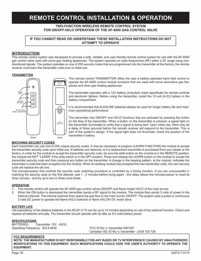
INTRODUCTIONThis remote control system was developed to provide a safe, reliable, and user-friendly remote control system for use with the AF-4000 gascontrolvalveusedwithsomegasheatingappliances.Thesystemoperatesonradiofrequencies(RF)withina20’rangeusingnon-directional signals. The system operates on one of 255 security codes that are programmed into the transmitter at the factory; the remote receiver must learn the transmitter code prior to initial use.
TRANSMITTERThis remote control TRANSMITTER offers the user a battery-operated hand held control to operatetheAF-4000controlmodulefunctionsthatareusedwithsomedecorativegasfire-places and other gas heating appliances.
Thetransmitteroperateswitha12Vbattery(Included)madespecificallyforremotecontrolsand electronic lighters. Before using the transmitter, install the 12-volt (A-23) battery in the battery compartment.
It is recommended that ALKALINE batteries always be used for longer battery life and maxi-mum operational performance.
The transmitter has ON/OFF and HI/LO functions that are activated by pressing the button on the face of the transmitter. When a button on the transmitter is pressed, a signal light on the transmitter illuminates to verify that a signal is being sent. Upon initial use, there may be a delay of three seconds before the remote receiver will respond to the transmitter. This is partofthesystem’sdesign.Ifthesignallightdoesnotilluminate,checkthepositionofthetransmitter’sbattery.
MATCHING SECURITY CODESEachtransmittercanuseoneof255uniquesecuritycodes.Itmaybenecessarytoprogram(LEARNFUNCTION)themoduletoacceptthe transmitter security code upon initial use, if batteries are replaced, or if a replacement transmitter is purchased from your dealer or the factory. In order for the module to accept the transmitter security code, be sure the slide button on the module is in the REMOTE position; the module will NOT “LEARN” if the slide switch is in the OFF position. Press and release the LEARN button on the module to accept the transmitter security code and then pressing any button on the transmitter. A change in the beeping pattern, at the module, indicates the transmitter’scodehasbeenacceptedintothemodule.Whenanexistingmodulehasacceptedthenewtransmittercode,thenewsecuritycode will replace the old one.The microprocessor that controls the security code matching procedure is controlled by a timing function. If you are unsuccessful in matchingthesecuritycodeonthefirstattempt,wait1-2minutesbeforetryingagain-thisdelayallowsthemicroprocessortoresetitstimer circuitry - and try up to two or three more times.
OpERATION1. ThisremotecontrolwilloperatetheAF-4000gascontrolvalvesON/OFFandflameheightHI/LOofthemainburner.2. When the ON button is depressed the transmitter sends a RF signal to the module. The module then sends 3 volts of power to the
internalsolenoid.TheinternalsolenoidthenopensthegasflowtothemainburnerON/OFF.Thesystemusesapulseorcontinuous3voltsDCpowertooperatetheflameHI/LOsolenoidorflameHI/LOWDCmotordrive.
BATTERY LIFELifeexpectancyofthealkalinebatteriesintheRCAF-3TXcanbeupto12monthsdependingonuseofthesolenoidfunction.Checkandreplace all batteries annually. The transmitter should operate with as little as 9.0 volts battery power.
SpECIFICATIONSBATTERIES: Transmitter 12V - (A23)OperatingFrequency:303.8MHZ FCCIDNo.’s:transmitterK9l1001 CanadianISCIDNo.’s:transmitter-2439102728
FCC REQUIREMENTSNOTE: THE MANUFACTURER IS NOT RESpONSIBLE FOR ANY RADIO OR TV INTERFERENCE CAUSED BY UNAUTHORIZED MODIFICATIONS TO THIS EQUIpMENT. SUCH MODIFICATIONS COULD VOID THE USER’S AUTHORITY TO OpERATE THE EQUIpMENT.
REMOTE CONTROL INSTALLATION & OpERATION

32272-7-0115 Page 19
Keep the control compartment, logs and burner area surrounding the logs clean by vacuuming or brushing area at least twice a year.THE LOGS CAN GET VERY HOT – HANDLE ONLY WHEN COOL.Always turn off gas to the pilot before cleaning. For relighting, refer
to lighting instructions located on the rating plate of the log set.
Neverobstructtheflowofthecombustionandventilationair.Keepthefrontofthefireplaceclearofallobstaclesandmaterials.
Leaveatleast36"clearancefromthefrontofthefireplace.
Screens should be closed during operation.
MAINTENANCE
Ifthegasqualityisbad,yourpilotmaynotstaylit,theburnersmayproducesootandtheheatermaybackfirewhenlit.Ifthegas quality or pressure is low, contact your local gas supplier immediately.
1. When ignitor button is pressed, there is no spark at pilot. a. Ignitor electrode positioned wrong - Replace pilot.b. Ignitorelectrodeisbroken-Replacepilot.c. Ignitor electrode not connected to ignitor cable - Reconnect
ignitor cable.d. Ignitor cable pinched or wet. Keep ignitor cable dry - Free
ignitor cable if pinched by any metal or tubing. e. Brokenignitorcable-Replaceignitorcable.f. Bad piezo ignitor - Replace piezo ignitor.
2. Appliance produces unwanted odors.a. Appliance burning vapors from paint, hair spray, glues, etc.
- Ventilate area. Stop using odor causing products while heater is running.
b. Gasleak-Locateandcorrectallleaks.
3. Appliance shuts off during use. (pilot and main burner are off.)a. Not enough fresh air is available for ODS/pilot to operate -
Open window and/or door for ventilation.b. Low line pressure - Contact local gas company.c. ODS/pilot is partially clogged - Clean ODS/pilot.d. Defective thermocouple - Replace pilot.
4. Appliance shuts off during use. (pilot stays on.)a. Lowlinepressure-Checklinepressuretothevalve.b. Defective thermopile - Check pilot flame, check wire
connections, output should be a minimum of 325 millivolts across. TH/TP and TP terminals with ON/OFF switch off.
5. Gas odor even when control knob is in OFF position.a. Gasleak-Locateandcorrectallleaks.b. Control valve defective - Replace control valve.
6. When ignitor button is pressed, there is spark at pilot, but no ignition.a. Gas supply turned off or manual shutoff valve closed - Turn
on gas supply or open manual shutoff valve.b. ControlknobnotinPILOTposition-Turncontrolknobto
PILOT position.c. ControlknobnotpressedinwhileinPILOTposition-Press
incontrolknobwhileinPILOTposition.d. Air in gas lines when installed - Continue holding down control
knob.Repeatignitingoperationuntilairisremoved.e. Pilot is clogged - Replace pilot assembly or get it
serviced.f. Gas regulator setting is not correct - Replace gas
regulator.
7. Pilot lights but flame goes out when control knob isreleased.
a. Controlknobnot fullypressed in-Press incontrolknobfully.
b. Controlknobnotpressedinlongenough-Afterpilotlights,keepcontrolknobpressedin30seconds.
c. Manual Shutoff valve not fully open - Fully open manual shutoff valve.
d. Thermocouple connection loose at control valve - Hand tighten until snug, then tighten 1/4 turn more.
e. Pilot flame not touching thermocouple, which allowsthermocoupletocool,causingpilotflametogoout.Thisproblem could be caused by either low gas pressure or dirty or partially clogged pilot - Contact local gas company.
f. Thermocouple damaged - Replace thermocouple.g. Control valve damaged - Replace control valve.
8. Burner does not light after pilot is lit.a. Burnerorificeclogged-Cleanburnerorreplacemainburner
orifice.b. Burner orifice diameter is too small - Replace burner
orifice.c. Inlet gas pressure is too low -Contact qualified service
person.
9. Ifburningatmainburnerorificeoccurs(aloud,roaringblow torch noise).a. Youmustturnoffburnerassemblyandcontactaqualified
service person.b. Manifold pressure is too low - Contact local gas company.c. Burner orifice clogged -Clean burner or replace burner
orifice.
10. Logs appear to smoke after initial operation.a. Vapors from paint or curing process of logs - Problem will
stop after a few hours of operation. Logheaterisintendedtobesmokeless.TurnOFFheater
andcallqualifiedserviceperson.
11. Heater produces a whistling noise when main burner is lit.a. TurningcontrolknobtoHIGHpositionwhenmainburneris
cold-TurncontrolknobtoLOWpositionandletwarmupfor a minute.
b. Air in gas line - Operate burner until air is removed from line.Havegaslinecheckedbylocalgascompany.
c. Dirtyorpartiallycloggedburnerorifice-Cleanburnerorreplaceburnerorifice.
12. No gas to pilot.a. LP-regulator shut down due to inlet pressure too high -
VerifyLPtankregulator is installedandsetat11"to13"w.c. Replace regulator on heater.
TurnapplianceOFFandallowtocoolbeforeservicing.Onlyaqualifiedservicepersonshouldserviceandrepairtheheater.
TROUBLESHOOTINGSYMpTOMS - pOSSIBLE CAUSES AND CORRECTIONS
32272-7-0115Page 20
pARTS LIST
Index No.
pART No.Description
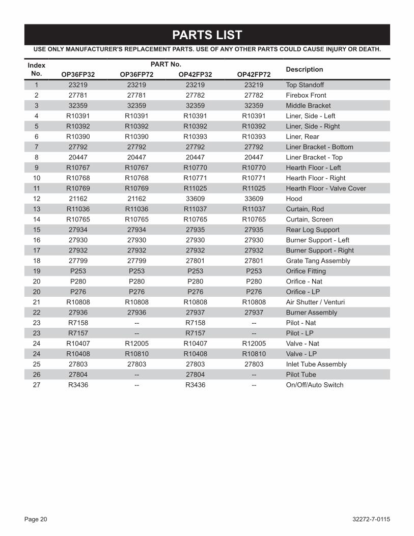
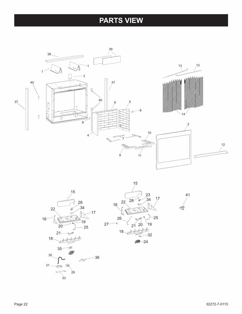
Op36Fp32 Op36Fp72 Op42Fp32 Op42Fp721 23219 23219 23219 23219 Top Standoff2 27781 27781 27782 27782 Firebox Front3 32359 32359 32359 32359 MiddleBracket4 R10391 R10391 R10391 R10391 Liner, Side - Left5 R10392 R10392 R10392 R10392 Liner, Side - Right6 R10390 R10390 R10393 R10393 Liner, Rear7 27792 27792 27792 27792 LinerBracket-Bottom8 20447 20447 20447 20447 LinerBracket-Top9 R10767 R10767 R10770 R10770 Hearth Floor - Left10 R10768 R10768 R10771 R10771 Hearth Floor - Right11 R10769 R10769 R11025 R11025 Hearth Floor - Valve Cover12 21162 21162 33609 33609 Hood13 R11036 R11036 R11037 R11037 Curtain, Rod14 R10765 R10765 R10765 R10765 Curtain, Screen15 27934 27934 27935 27935 Rear Log Support16 27930 27930 27930 27930 Burner Support - Left17 27932 27932 27932 27932 Burner Support - Right18 27799 27799 27801 27801 Grate Tang Assembly19 P253 P253 P253 P253 OrificeFitting20 P280 P280 P280 P280 Orifice-Nat20 P276 P276 P276 P276 Orifice-LP21 R10808 R10808 R10808 R10808 Air Shutter / Venturi22 27936 27936 27937 27937 Burner Assembly23 R7158 -- R7158 -- Pilot - Nat23 R7157 -- R7157 -- Pilot - LP24 R10407 R12005 R10407 R12005 Valve - Nat24 R10408 R10810 R10408 R10810 Valve - LP25 27803 27803 27803 27803 Inlet Tube Assembly26 27804 -- 27804 -- Pilot Tube27 R3436 -- R3436 -- On/Off/Auto Switch
USE ONLY MANUFACTURER'S REpLACEMENT pARTS. USE OF ANY OTHER pARTS COULD CAUSE INjURY OR DEATH.

32272-7-0115 Page 21
pARTS LIST
28 R1155 R10814 R1155 R10814 SparkProbe29 -- R10813 -- R10813 Remote Receiver with Harness30 R10954 R10812 R10954 R10812 Wire Harness31 -- R10811 -- R10811 Control Module32 R9761 -- R9761 -- Piezo Ignigtor33 -- 28539 -- 28539 Control Module Base34 28088 27800 28088 27800 IgnitorBracket35 -- 28081 -- 28081 ValveBracket36 -- 31514 -- 31514 Water Shield37 32231 32231 32331 32231 Metal Channel - Side38 32233 32233 32234 32234 Metal Channel - Top39 R11681 R11681 R11683 R11683 Non-Combustible Board40 10554 10554 10554 10554 Flanges
41 R11927 R11927 R11927 R11927 Shut-Off Valve 3/8" M-Flare x 1/2" FIP
NS 28748 28748 28748 28748 Gas Line CoverNS -- R10815 -- R10815 Remote Control
NS - Not Shown
Index No.
pART No.Description
Op36Fp32 Op36Fp72 Op42Fp32 Op42Fp72
USE ONLY MANUFACTURER'S REpLACEMENT pARTS. USE OF ANY OTHER pARTS COULD CAUSE INjURY OR DEATH.
32272-7-0115Page 22
pARTS VIEW
29
31
30
10
8
6 5
1
12
2
1313
14
37
8
9 11
7
4
33
36
35
18
21
20
1916
22
28
15
17
25
34
15
16
2317
26
27
22 28 34
21 20 19
25
18
24
32
37
1
38
39
3
4142
40
40

32272-7-0115 Page 23
To Order Parts Under Warranty, please contact your local Empire dealer. See the dealer locator at www.empirecomfort.com. To provide warranty service, your dealer will need your name and address, purchase date and serial number, and the nature of the problem with the unit. To Order Parts After the Warranty Period, please contact your dealer or one of the Master Parts Distributors listed below. Thislistchangesfromtimetotime.Forthecurrentlist,pleaseclickontheMasterPartsbuttonatwww.empirecomfort.com.Please note: Master Parts Distributors are independent businesses that stock the most commonly ordered OriginalEquipmentrepairpartsforHeaters,Grills,andFireplacesmanufacturedbyEmpireComfortSystemsInc.
MASTER pARTS DISTRIBUTOR LIST
parts Not Under WarrantyParts can be ordered through your Service Person, Dealer, or a Master Parts Distributor. See this page for the Master Parts Distribu-tors list. For best results, the service person or dealer should order parts through the distributor. Parts can be shipped directly to the service person/dealer.Warranty partsWarranty parts will need a proof of purchase and can be ordered by your Service Person or Dealer. Proof of purchase is required for warranty parts.AllpartslistedinthePartsListhaveaPartNumber.Whenorderingparts,firstobtaintheModelNumberandSerialNumberfromthenameplateonyourequipment.ThendeterminethePartNumber(not the Index Number) and the Description of each part from the fol-lowing illustration and part list. Be sure to give all this information . . .
Appliance Model Number Part Description
Appliance Serial Number Part Number
Type of Gas (Propane or Natural)
Do not order bolts, screws, washers or nuts. They are standard hardware items and can be purchased at any local hardware store. Shipmentscontingentuponstrikes,firesandallcausesbeyondourcontrol.
HOW TO ORDER REpAIR pARTS
Dey Distributing1401WillowLakeBoulevardVadnais Heights, MN 55101
phone: 651-490-9191Toll Free: 800-397-1339Website: www.deydistributing.comparts: Heater, Hearth and Grills
Victor Division of F. W. Webb Company200 Locust StreetHartford, CT 06114
phone: 860-722-2433Toll Free: 800-243-9360Fax: 860-293-0479Toll Free Fax: 800-274-2004Websites: www.fwwebb.com & www.victormfg.comparts: Heater, Hearth and Grills
East Coast Energy products10 East Route 36West Long Branch, NJ 07764
phone: 732-870-8809Toll Free: 800-755-8809Fax: 732-870-8811Website: www.eastcoastenergy.comparts: Heater, Hearth and Grills
Able Distributors2501 North Central AvenueChicago, IL 60639
phone: 773-889-5555Toll Free: 800-880-2253Fax: 773-466-1118Website: www. abledistributors.comparts: Heater

32272-7-0115Page 24
EMPIREEMPIREComfort Systems
Empire Comfort Systems Inc.918 Freeburg Ave. Belleville, IL 62220
Ifyouhaveageneralquestionaboutourproducts,[email protected]. Ifyouhaveaserviceorrepairquestion,pleasecontactyourdealer.
www.empirecomfort.com
WARRANTY TERMSEmpire Comfort Systems Inc. warranties this hearth product to be free from defects at the time of purchase and for the pe-riodsspecifiedbelow.Hearthproductsmustbeinstalledbyaqualifiedtechnicianandmustbemaintainedandoperatedsafely,inaccordancewiththeinstructionsintheowner’smanual.Thiswarrantyappliestotheoriginalpurchaseronlyandisnottransferable.Allwarrantyrepairsmustbeaccomplishedbyaqualifiedgasappliancetechnician.
Limited Five-Year Parts Warranty – All Components (Except Remote Controls, Thermostats, Accessories and Replacement Parts) Shouldanypartfailbecauseofdefectiveworkmanshipormaterialwithinfiveyearsfromthedateofpurchase,EmpirewillrepairorreplaceatEmpire’soption.
Limited One-Year Parts Warranty – Remote Controls, Thermostats, Accessories, and Parts Shouldanyremotecontrol,thermostat,accessory,orotherpartfailbecauseofdefectiveworkmanshipwithinoneyearfromthedateofpurchase,EmpirewillrepairorreplaceatEmpire’soption.
Duties of the Owner Theappliancemustbeinstalledbyaqualifiedinstallerandoperatedinaccordancewiththeinstructionsfurnishedwith the appliance. Abillofsale,cancelledcheck,orpaymentrecordshouldbekepttoverifypurchasedateandestablishwarrantyperiod. Ready access to the appliance for service.
What Is Not Covered Damages that might result from the use, misuse, or improper installation of this appliance. Travel, diagnostic costs and freight charges on warranted parts to and from the factory. Claimsthatdonotinvolvedefectiveworkmanshipormaterials. Unauthorized service or parts replacements. Removal and reinstallation cost. Inoperableduetoimproperorlackofmaintenance.
How To Get Service Tomakeaclaimunderthiswarranty,pleasehaveyourreceiptavailableandcontactyourinstallingdealer.Pro-videthedealerwiththemodelnumber,serialnumber,typeofgas,andpurchaseverification.Theinstallingdealerisre-sponsibleforprovidingserviceandwillcontactthefactorytoinitiateanywarrantedpartsreplacements.Empirewillmakereplacement parts available at the factory. Shipping expenses are not covered. If, after contacting your Empire dealer, service received has not been satisfactory, contact: Consumer Rela-tions Department, Empire Comfort Systems Inc., PO Box 529, Belleville, Illinois 62222, or send an e-mail to [email protected] with “Consumer Relations” in the subject line.
Your Rights Under State Law Thiswarrantygivesyouspecificlegalrights,andyoumayalsohaveotherrights,whichvaryfromstatetostate.