Embed Size (px)
Citation preview

INSTALLATIONINSTRUCTIONS
MUSTANG GT ‘05 - ‘10STAINLESS STEEL HEADERS
LIT-884, REV 3
4.6 LITER ENGINE
Note: We do our best to ensure the instructions in the box are the latest version. However in
some cases where the system does not change for a new model year, inventory on the shelf may
not have the latest version of the instruction manual. If you do not see your model or application
listed above, please feel free to contact us at 800-848-5850 or [email protected] for
an updated instruction manual. We assure you the parts in the box are correct. The instructions
may have added notes for a specific model year update.
PART NUMBERS722-54310722-54320722-54330722-64320722-64330
These products are intended for racing and off-road applications. Not legal for sale or use in the state of California, nor in states which have adopted California emission standards.
www.DynatechHeaders.com | Copyright 2017 - AFCO Performance Group
Copyright 2017 - AFCO Performance Group www.DYNATECHHEADERS.com2
Installation Instructions
Congratulations on your purchase of the Dynatech header system. This system is second to none in quality, performance, and ease of installation. Please read and understand each of the steps involved with the removal of your old system and the installation of your new header system kit. While slight variations in either the header or the vehicle may cause minor differences in the exact order of steps listed in this document, the following narrative and pictorial information should guide you during the removal and installation process leading to a completely satisfactory install of your new header system.
Dynatech highly recommends hiring a professional installer, one that is familiar with the installation of off-road exhaust products. Headers are designed to increase the performance of your vehicle, and as such are designed differently than your stock exhaust system. Extra care must be taken to ensure that hoses, cables, electrical lines, fuel lines, hydraulic lines, or any other objects are not in contact with, or located too close to your installed system. (Nothing should be allowed to touch or be located close to the header/exhaust system.)
Dynatech will repair or replace any products found upon our inspection to be defective in workmanship or material within 12 months from date of purchase for the original purchaser.
Dynatech is not responsible for any exhaust product that has been improperly installed, crashed, welded to, or modified in any way. Dynatech does not cover damage to any related components. Neither the seller nor Dynatech will be responsible or liable for any loss, damage, or injury resulting from the direct or indirect use of this product or inability by the purchaser to determine proper use or application of this product. Dynatech competition exhaust products are built for off-highway use only and are not intended for use on street legal, pollution controlled vehicles.
The Dynatech Team takes pride in providing the utmost in quality and performance. Should you have a concern about the product you receive, please contact Dynatech Customer Service at [email protected].
Note: These products are intended for racing and off-road applications. Not legal for sale or use in the State of California, nor in states which have adopted California emission standards.
www.DYNATECHHEADERS.com Copyright 2017 - AFCO Performance GroupCopyright 2017 - AFCO Performance Group www.DYNATECHHEADERS.com3
What’s in your new header kit?
Your exhaust system should contain all of the following parts. Please inventory each part prior to proceeding with the installation.
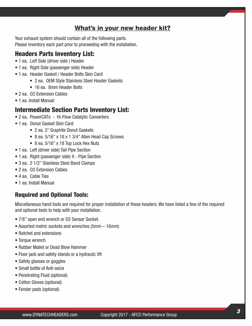
Headers Parts Inventory List:• 1 ea. Left Side (driver side ) Header• 1 ea. Right Side (passenger side) Header• 1 ea. Header Gasket / Header Bolts Skin Card • 2 ea. OEM Style Stainless Steel Header Gaskets • 16 ea. 8mm Header Bolts • 2 ea. O2 Extension Cables• 1 ea. Install Manual
Intermediate Section Parts Inventory List:• 2 ea. PowerCATs - Hi-Flow Catalytic Converters• 1 ea. Donut Gasket Skin Card • 2 ea. 3” Graphite Donut Gaskets • 8 ea. 5/16” x 18 x 1 3/4” Allen Head Cap Screws • 8 ea. 5/16” x 18 Top Lock Hex Nuts• 1 ea. Left (driver side) Tail Pipe Section• 1 ea. Right (passenger side) X - Pipe Section• 3 ea. 2 1/2” Stainless Steel Band Clamps• 2 ea. O2 Extension Cables• 4 ea. Cable Ties• 1 ea. Install Manual
Required and Optional Tools:Miscellaneous hand tools are required for proper installation of these headers. We have listed a few of the required and optional tools to help with your installation.
• 7/8” open end wrench or O2 Sensor Socket.• Assorted metric sockets and wrenches (5mm – 16mm)• Ratchet and extensions• Torque wrench• Rubber Mallet or Dead Blow Hammer• Floor jack and safety stands or a hydraulic lift• Safety glasses or goggles• Small bottle of Anti-seize• Penetrating Fluid (optional)• Cotton Gloves (optional)• Fender pads (optional)
Copyright 2017 - AFCO Performance Group www.DYNATECHHEADERS.com4
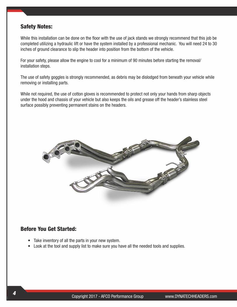
Safety Notes:
While this installation can be done on the floor with the use of jack stands we strongly recommend that this job be completed utilizing a hydraulic lift or have the system installed by a professional mechanic. You will need 24 to 30 inches of ground clearance to slip the header into position from the bottom of the vehicle.
For your safety, please allow the engine to cool for a minimum of 90 minutes before starting the removal/ installation steps.
The use of safety goggles is strongly recommended, as debris may be dislodged from beneath your vehicle while removing or installing parts.
While not required, the use of cotton gloves is recommended to protect not only your hands from sharp objects under the hood and chassis of your vehicle but also keeps the oils and grease off the header’s stainless steel surface possibly preventing permanent stains on the headers.
Before You Get Started:
• Take inventory of all the parts in your new system. • Look at the tool and supply list to make sure you have all the needed tools and supplies.
www.DYNATECHHEADERS.com Copyright 2017 - AFCO Performance GroupCopyright 2017 - AFCO Performance Group www.DYNATECHHEADERS.com5
Old System Removal:Stock System Removal: (2005 Ford Mustang GT w/4.6l engine)
Under the Hood
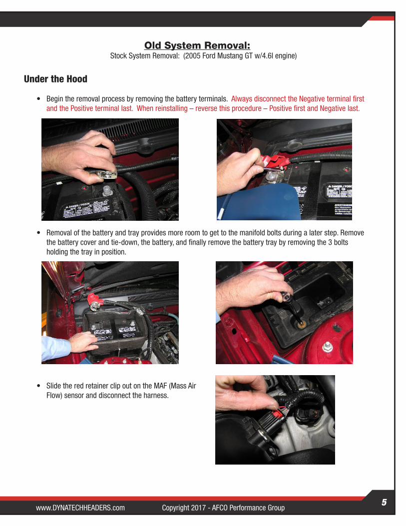
• Begin the removal process by removing the battery terminals. Always disconnect the Negative terminal first and the Positive terminal last. When reinstalling – reverse this procedure – Positive first and Negative last.
• Removal of the battery and tray provides more room to get to the manifold bolts during a later step. Remove the battery cover and tie-down, the battery, and finally remove the battery tray by removing the 3 bolts holding the tray in position.
• Slide the red retainer clip out on the MAF (Mass Air Flow) sensor and disconnect the harness.
Copyright 2017 - AFCO Performance Group www.DYNATECHHEADERS.com6
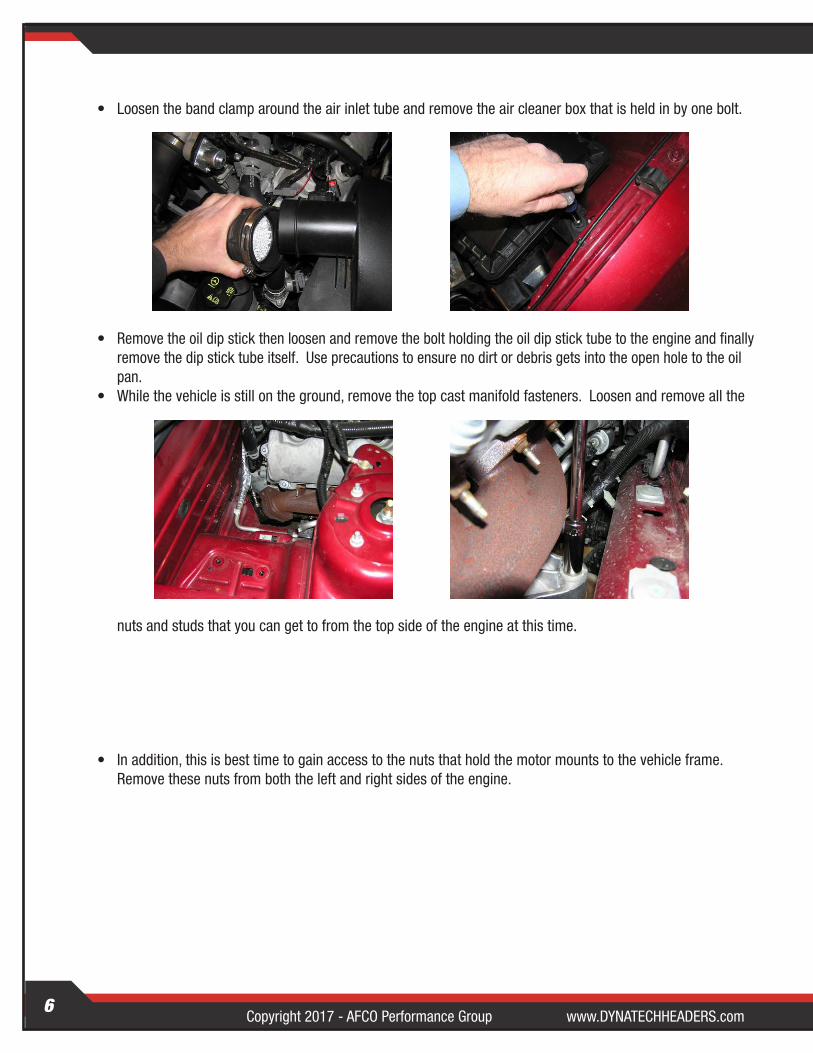
• Loosen the band clamp around the air inlet tube and remove the air cleaner box that is held in by one bolt.
• Remove the oil dip stick then loosen and remove the bolt holding the oil dip stick tube to the engine and finally remove the dip stick tube itself. Use precautions to ensure no dirt or debris gets into the open hole to the oil pan.
• While the vehicle is still on the ground, remove the top cast manifold fasteners. Loosen and remove all the
nuts and studs that you can get to from the top side of the engine at this time.
• In addition, this is best time to gain access to the nuts that hold the motor mounts to the vehicle frame. Remove these nuts from both the left and right sides of the engine.
www.DYNATECHHEADERS.com Copyright 2017 - AFCO Performance GroupCopyright 2017 - AFCO Performance Group www.DYNATECHHEADERS.com7
Under the Vehicle
The use of penetrating oil is recommended to aid in the removal of stubborn bolts and nuts. Do not use penetrating oil on any of the sensors throughout the system particularly the O2 sensors.
• Raise the vehicle off the ground using a floor jack and jack stands or use a hydraulic lift. (We strongly recommend the use of a hydraulic lift)
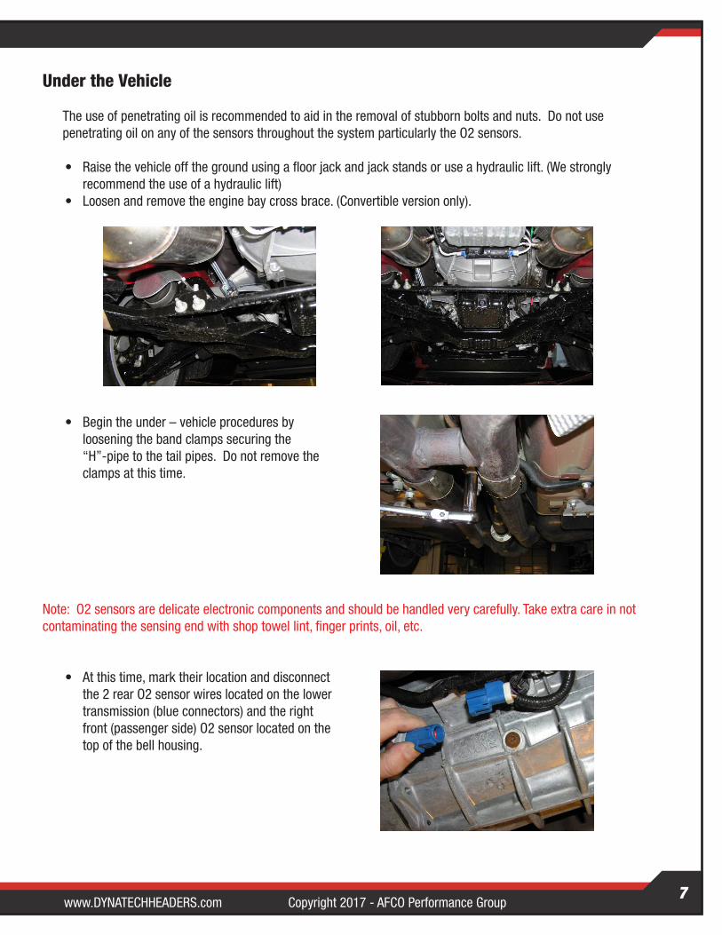
• Loosen and remove the engine bay cross brace. (Convertible version only).
• Begin the under – vehicle procedures by loosening the band clamps securing the “H”-pipe to the tail pipes. Do not remove the clamps at this time.
Note: O2 sensors are delicate electronic components and should be handled very carefully. Take extra care in not contaminating the sensing end with shop towel lint, finger prints, oil, etc.
• At this time, mark their location and disconnect the 2 rear O2 sensor wires located on the lower transmission (blue connectors) and the right front (passenger side) O2 sensor located on the top of the bell housing.
Copyright 2017 - AFCO Performance Group www.DYNATECHHEADERS.com8
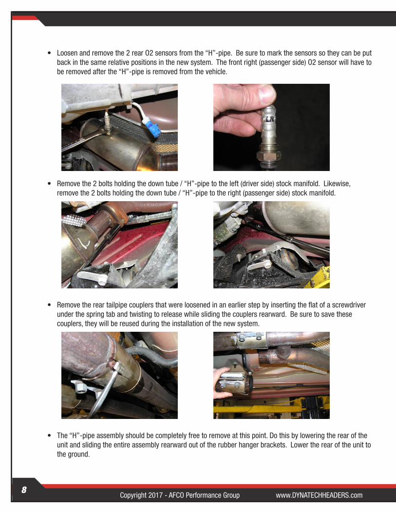
• Loosen and remove the 2 rear O2 sensors from the “H”-pipe. Be sure to mark the sensors so they can be put back in the same relative positions in the new system. The front right (passenger side) O2 sensor will have to be removed after the “H”-pipe is removed from the vehicle.
• Remove the 2 bolts holding the down tube / “H”-pipe to the left (driver side) stock manifold. Likewise, remove the 2 bolts holding the down tube / “H”-pipe to the right (passenger side) stock manifold.
• Remove the rear tailpipe couplers that were loosened in an earlier step by inserting the flat of a screwdriver under the spring tab and twisting to release while sliding the couplers rearward. Be sure to save these couplers, they will be reused during the installation of the new system.
• The “H”-pipe assembly should be completely free to remove at this point. Do this by lowering the rear of the unit and sliding the entire assembly rearward out of the rubber hanger brackets. Lower the rear of the unit to the ground.
www.DYNATECHHEADERS.com Copyright 2017 - AFCO Performance GroupCopyright 2017 - AFCO Performance Group www.DYNATECHHEADERS.com9
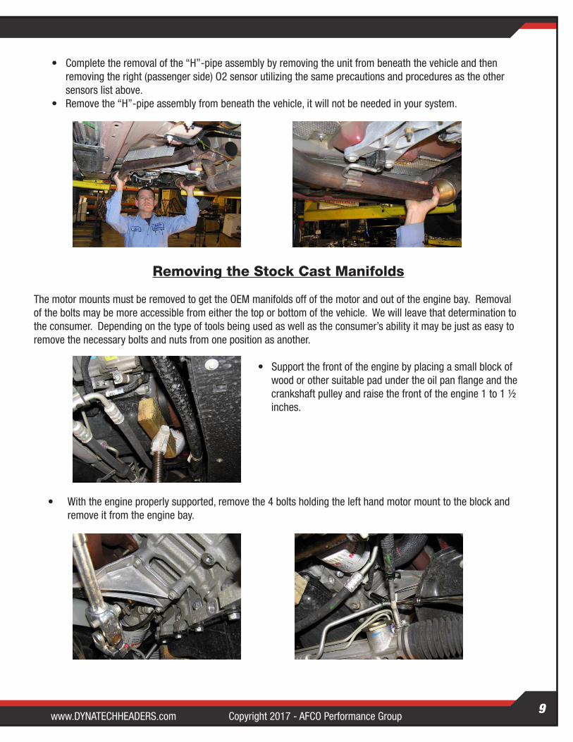
• Complete the removal of the “H”-pipe assembly by removing the unit from beneath the vehicle and then removing the right (passenger side) O2 sensor utilizing the same precautions and procedures as the other sensors list above.
• Remove the “H”-pipe assembly from beneath the vehicle, it will not be needed in your system.
Removing the Stock Cast Manifolds
The motor mounts must be removed to get the OEM manifolds off of the motor and out of the engine bay. Removal of the bolts may be more accessible from either the top or bottom of the vehicle. We will leave that determination to the consumer. Depending on the type of tools being used as well as the consumer’s ability it may be just as easy to remove the necessary bolts and nuts from one position as another.
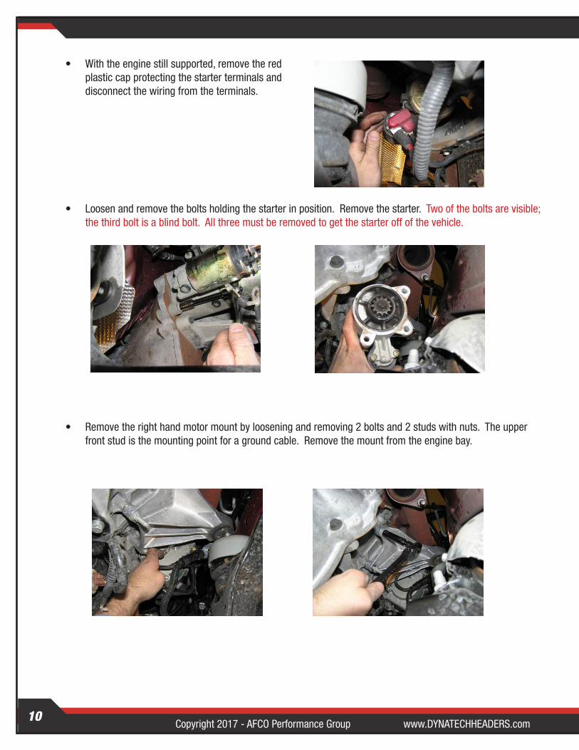
• Support the front of the engine by placing a small block of wood or other suitable pad under the oil pan flange and the crankshaft pulley and raise the front of the engine 1 to 1 ½ inches.
• With the engine properly supported, remove the 4 bolts holding the left hand motor mount to the block and remove it from the engine bay.
Copyright 2017 - AFCO Performance Group www.DYNATECHHEADERS.com10
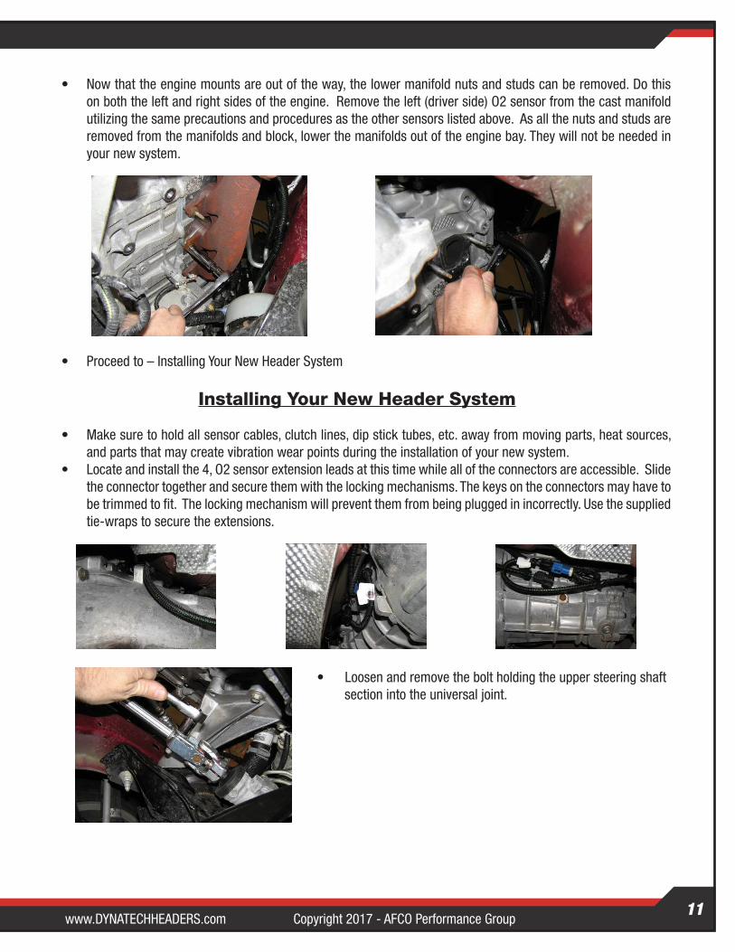
• With the engine still supported, remove the red plastic cap protecting the starter terminals and disconnect the wiring from the terminals.
• Loosen and remove the bolts holding the starter in position. Remove the starter. Two of the bolts are visible; the third bolt is a blind bolt. All three must be removed to get the starter off of the vehicle.
• Remove the right hand motor mount by loosening and removing 2 bolts and 2 studs with nuts. The upper front stud is the mounting point for a ground cable. Remove the mount from the engine bay.
www.DYNATECHHEADERS.com Copyright 2017 - AFCO Performance GroupCopyright 2017 - AFCO Performance Group www.DYNATECHHEADERS.com11
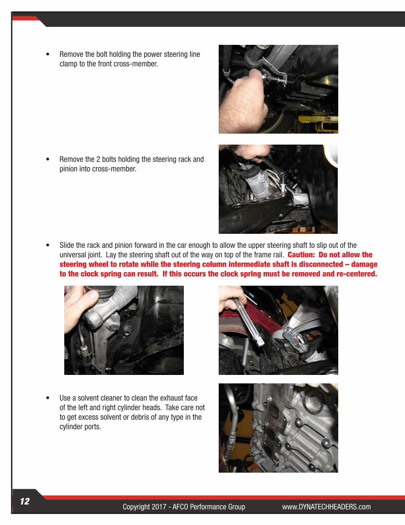
• Now that the engine mounts are out of the way, the lower manifold nuts and studs can be removed. Do this on both the left and right sides of the engine. Remove the left (driver side) O2 sensor from the cast manifold utilizing the same precautions and procedures as the other sensors listed above. As all the nuts and studs are removed from the manifolds and block, lower the manifolds out of the engine bay. They will not be needed in your new system.
• Proceed to – Installing Your New Header System
Installing Your New Header System
• Make sure to hold all sensor cables, clutch lines, dip stick tubes, etc. away from moving parts, heat sources, and parts that may create vibration wear points during the installation of your new system.
• Locate and install the 4, O2 sensor extension leads at this time while all of the connectors are accessible. Slide the connector together and secure them with the locking mechanisms. The keys on the connectors may have to be trimmed to fit. The locking mechanism will prevent them from being plugged in incorrectly. Use the supplied tie-wraps to secure the extensions.
• Loosen and remove the bolt holding the upper steering shaft section into the universal joint.
Copyright 2017 - AFCO Performance Group www.DYNATECHHEADERS.com12
• Remove the bolt holding the power steering line clamp to the front cross-member.
• Remove the 2 bolts holding the steering rack and pinion into cross-member.
• Slide the rack and pinion forward in the car enough to allow the upper steering shaft to slip out of the universal joint. Lay the steering shaft out of the way on top of the frame rail. Caution: Do not allow the steering wheel to rotate while the steering column intermediate shaft is disconnected – damage to the clock spring can result. If this occurs the clock spring must be removed and re-centered.
• Use a solvent cleaner to clean the exhaust face of the left and right cylinder heads. Take care not to get excess solvent or debris of any type in the cylinder ports.
www.DYNATECHHEADERS.com Copyright 2017 - AFCO Performance GroupCopyright 2017 - AFCO Performance Group www.DYNATECHHEADERS.com13
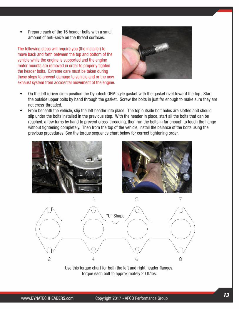
• Prepare each of the 16 header bolts with a small amount of anti-seize on the thread surfaces.
The following steps will require you (the installer) to move back and forth between the top and bottom of the vehicle while the engine is supported and the engine motor mounts are removed in order to properly tighten the header bolts. Extreme care must be taken during these steps to prevent damage to vehicle and or the new exhaust system from accidental movement of the engine.
• On the left (driver side) position the Dynatech OEM style gasket with the gasket rivet toward the top. Start the outside upper bolts by hand through the gasket. Screw the bolts in just far enough to make sure they are not cross-threaded.
• From beneath the vehicle, slip the left header into place. The top outside bolt holes are slotted and should slip under the bolts installed in the previous step. With the header in place, start all the bolts that can be reached, a few turns by hand to prevent cross-threading, then run the bolts in far enough to touch the flange without tightening completely. Then from the top of the vehicle, install the balance of the bolts using the previous procedures. See the torque sequence chart below for correct tightening order.
Use this torque chart for both the left and right header flanges.Torque each bolt to approximately 20 ft/lbs.
Copyright 2017 - AFCO Performance Group www.DYNATECHHEADERS.com14
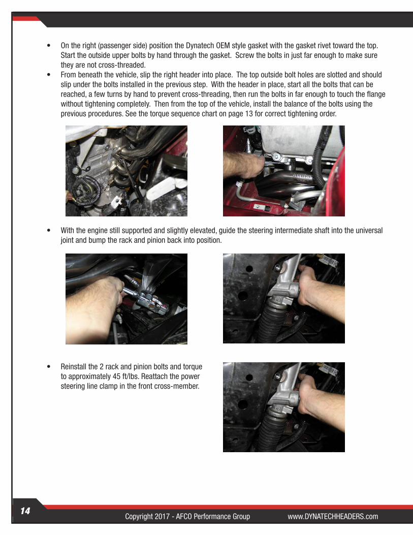
• On the right (passenger side) position the Dynatech OEM style gasket with the gasket rivet toward the top. Start the outside upper bolts by hand through the gasket. Screw the bolts in just far enough to make sure they are not cross-threaded.
• From beneath the vehicle, slip the right header into place. The top outside bolt holes are slotted and should slip under the bolts installed in the previous step. With the header in place, start all the bolts that can be reached, a few turns by hand to prevent cross-threading, then run the bolts in far enough to touch the flange without tightening completely. Then from the top of the vehicle, install the balance of the bolts using the previous procedures. See the torque sequence chart on page 13 for correct tightening order.
• With the engine still supported and slightly elevated, guide the steering intermediate shaft into the universal joint and bump the rack and pinion back into position.
• Reinstall the 2 rack and pinion bolts and torque to approximately 45 ft/lbs. Reattach the power steering line clamp in the front cross-member.
www.DYNATECHHEADERS.com Copyright 2017 - AFCO Performance GroupCopyright 2017 - AFCO Performance Group www.DYNATECHHEADERS.com15
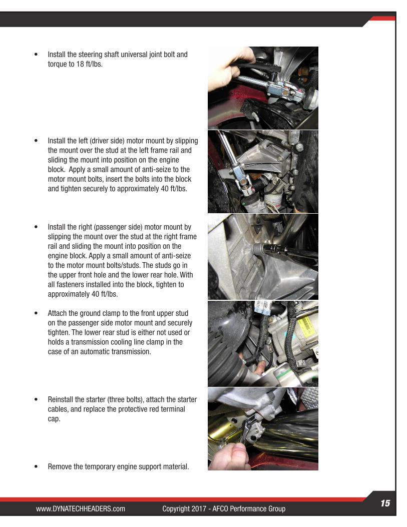
• Install the steering shaft universal joint bolt and torque to 18 ft/lbs.
• Install the left (driver side) motor mount by slipping the mount over the stud at the left frame rail and sliding the mount into position on the engine block. Apply a small amount of anti-seize to the motor mount bolts, insert the bolts into the block and tighten securely to approximately 40 ft/lbs.
• Install the right (passenger side) motor mount by slipping the mount over the stud at the right frame rail and sliding the mount into position on the engine block. Apply a small amount of anti-seize to the motor mount bolts/studs. The studs go in the upper front hole and the lower rear hole. With all fasteners installed into the block, tighten to approximately 40 ft/lbs.
• Attach the ground clamp to the front upper stud on the passenger side motor mount and securely tighten. The lower rear stud is either not used or holds a transmission cooling line clamp in the case of an automatic transmission.
• Reinstall the starter (three bolts), attach the starter cables, and replace the protective red terminal cap.
• Remove the temporary engine support material.
Copyright 2017 - AFCO Performance Group www.DYNATECHHEADERS.com16
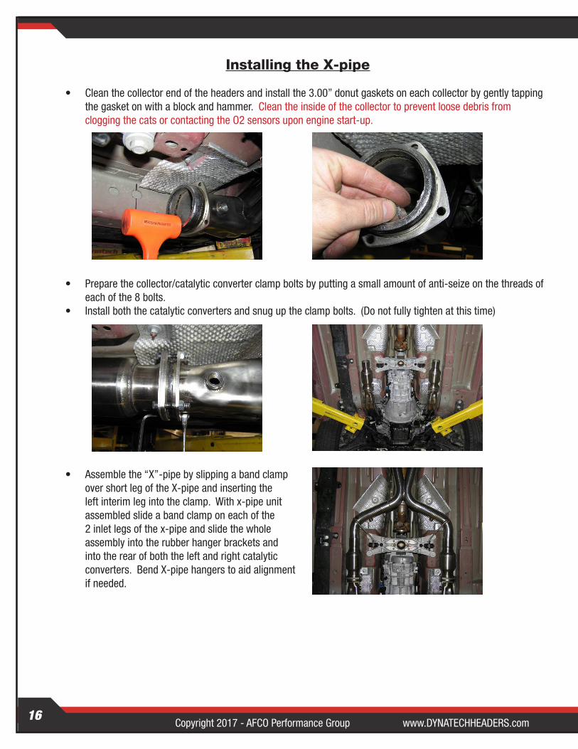
Installing the X-pipe
• Clean the collector end of the headers and install the 3.00” donut gaskets on each collector by gently tapping the gasket on with a block and hammer. Clean the inside of the collector to prevent loose debris from clogging the cats or contacting the O2 sensors upon engine start-up.
• Prepare the collector/catalytic converter clamp bolts by putting a small amount of anti-seize on the threads of each of the 8 bolts.
• Install both the catalytic converters and snug up the clamp bolts. (Do not fully tighten at this time)
• Assemble the “X”-pipe by slipping a band clamp over short leg of the X-pipe and inserting the left interim leg into the clamp. With x-pipe unit assembled slide a band clamp on each of the 2 inlet legs of the x-pipe and slide the whole assembly into the rubber hanger brackets and into the rear of both the left and right catalytic converters. Bend X-pipe hangers to aid alignment if needed.
www.DYNATECHHEADERS.com Copyright 2017 - AFCO Performance GroupCopyright 2017 - AFCO Performance Group www.DYNATECHHEADERS.com17
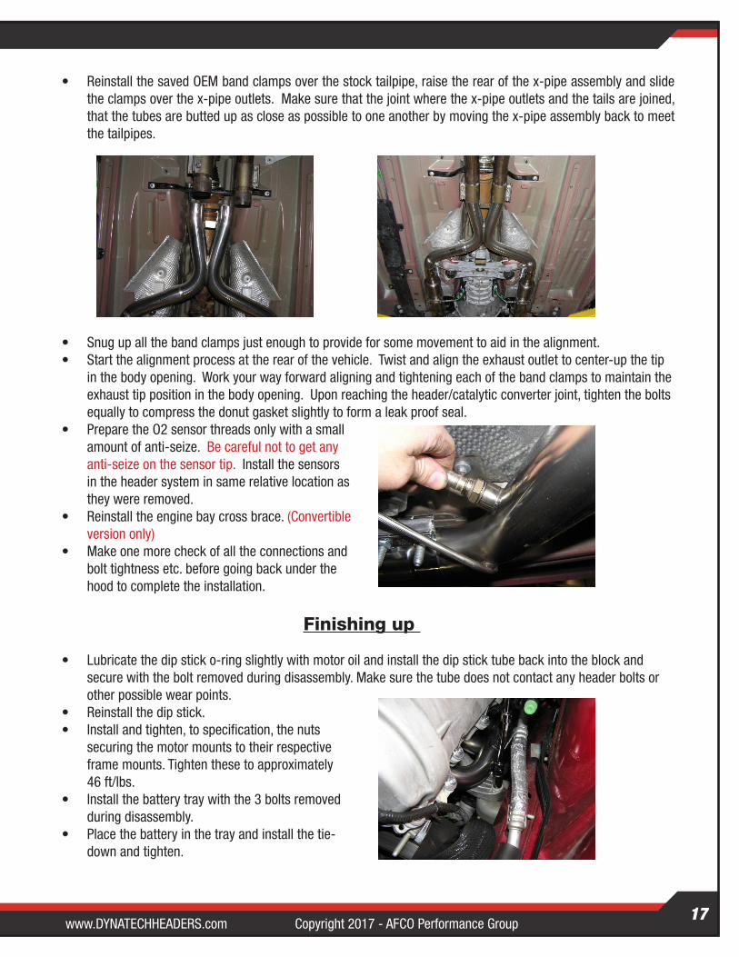
• Reinstall the saved OEM band clamps over the stock tailpipe, raise the rear of the x-pipe assembly and slide the clamps over the x-pipe outlets. Make sure that the joint where the x-pipe outlets and the tails are joined, that the tubes are butted up as close as possible to one another by moving the x-pipe assembly back to meet the tailpipes.
• Snug up all the band clamps just enough to provide for some movement to aid in the alignment.• Start the alignment process at the rear of the vehicle. Twist and align the exhaust outlet to center-up the tip
in the body opening. Work your way forward aligning and tightening each of the band clamps to maintain the exhaust tip position in the body opening. Upon reaching the header/catalytic converter joint, tighten the bolts equally to compress the donut gasket slightly to form a leak proof seal.
• Prepare the O2 sensor threads only with a small amount of anti-seize. Be careful not to get any anti-seize on the sensor tip. Install the sensors in the header system in same relative location as they were removed.
• Reinstall the engine bay cross brace. (Convertible version only)
• Make one more check of all the connections and bolt tightness etc. before going back under the hood to complete the installation.
Finishing up
• Lubricate the dip stick o-ring slightly with motor oil and install the dip stick tube back into the block and secure with the bolt removed during disassembly. Make sure the tube does not contact any header bolts or other possible wear points.
• Reinstall the dip stick.• Install and tighten, to specification, the nuts
securing the motor mounts to their respective frame mounts. Tighten these to approximately 46 ft/lbs.
• Install the battery tray with the 3 bolts removed during disassembly.
• Place the battery in the tray and install the tie-down and tighten.
Copyright 2017 - AFCO Performance Group www.DYNATECHHEADERS.com18
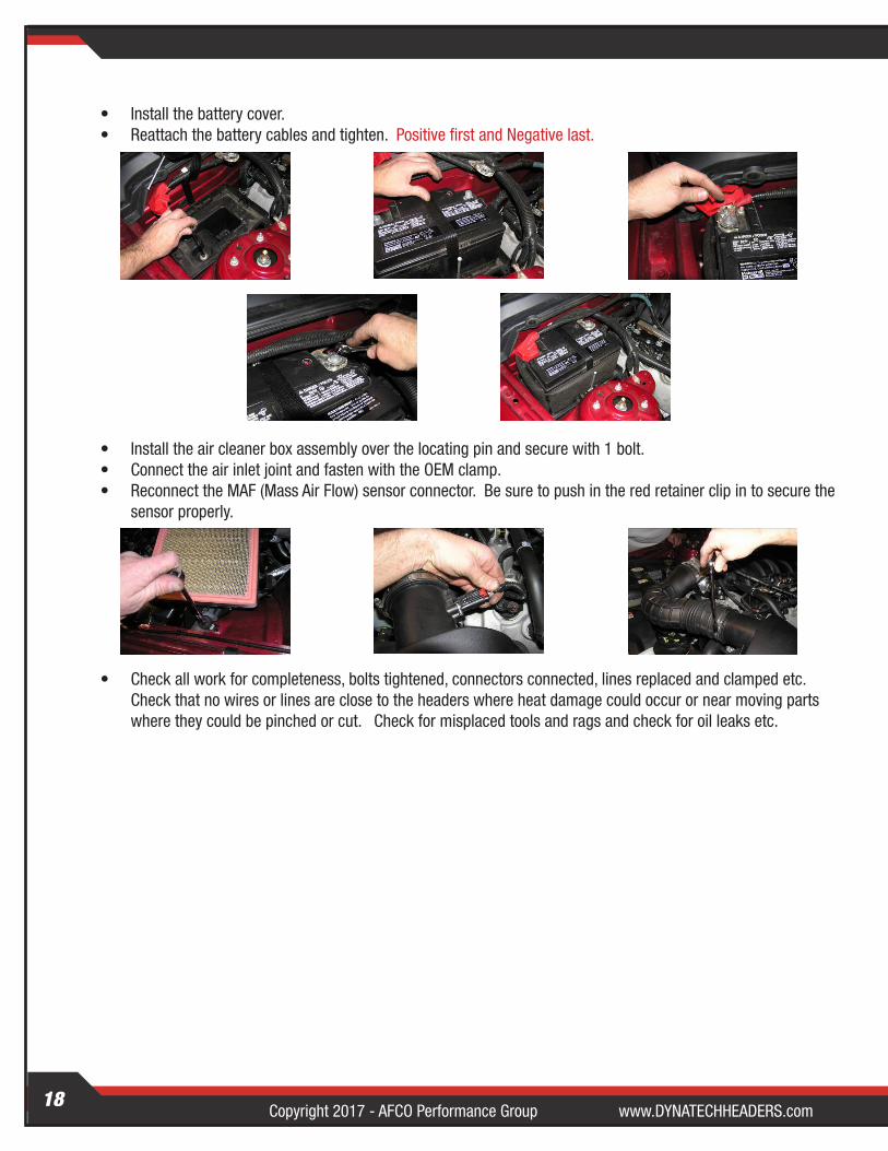
• Install the battery cover.• Reattach the battery cables and tighten. Positive first and Negative last.
• Install the air cleaner box assembly over the locating pin and secure with 1 bolt.• Connect the air inlet joint and fasten with the OEM clamp.• Reconnect the MAF (Mass Air Flow) sensor connector. Be sure to push in the red retainer clip in to secure the
sensor properly.
• Check all work for completeness, bolts tightened, connectors connected, lines replaced and clamped etc. Check that no wires or lines are close to the headers where heat damage could occur or near moving parts where they could be pinched or cut. Check for misplaced tools and rags and check for oil leaks etc.
www.DYNATECHHEADERS.com Copyright 2017 - AFCO Performance GroupCopyright 2017 - AFCO Performance Group www.DYNATECHHEADERS.com19
Final Checks: Caution: Once again, verify that all hoses, cables, electrical lines, fuel lines, hydraulic lines, or any other objects are not in contact with, or located too closely to your installed system. (Nothing should be allowed to touch or be located close to the header/exhaust system.)
• Check your work. No wiring, fluid lines, sensors, steering components, etc should come in contact with any part of the header or with any area that may cause heat damage or mechanical damage.
• Start the engine. Observe the “Check Engine Light”.
Note: In some instances you may experience a check engine light after the installation of an aftermarket exhaust system. If this occurs please contact Dynatech at 1-800-848-5850 and ask for customer service or e-mail [email protected].
• Listen for any exhaust leak “ticking” sounds. Check around each clamp and gasketed joint for leaks. If any are found, check to see that the gasket is properly installed and the joint or clamp is tightened properly.
• Verify that steering shaft and its bolt modification does not come in contact with or bind against the header as the steering wheel is turned to full lock to both the left and the right.
All bolts and connections should be retightened as necessary after the system has gone through several thermal cycles and as needed thereafter.
This completes the installation of your system. Go back over all the connections to check tightness,tube clearances, and brackets before starting the vehicle. Once you are satisfied that the system is correctly aligned and tightened, start the engine and check for leaks. If any are found, retighten the fasteners around the clamp at issue. All fasteners should be rechecked after the system has gone through several thermal cycles.
We make every effort to build our products to the highest standards of workmanship and materials possible. This also applies to our documentation. If you find points in our instruction manual that you feel need to be clarified or changed, please e-mail us your comments at [email protected]. We will use them to enhance our documentation.

For more Dynatech products visit us on our website!
Follow us on Facebook!
Dynatech continues to be the exhaust leader in all forms of racing and high performance applications. Advances in engineering, design and performance keep Dynatech products at the forefront of innovation, quality and performance. For 100% satisfaction, find us online at DynatechHeaders.com.
For the latest in product development information, install videos, technical manuals, technical tips and event schedules, find us online at Facebook.com/DynatechHeaders.
These products are intended for racing and off-road applications. Not legal for sale or use in the state of California, nor in states which have adopted California emission standards.
Dynatech Competition Exhaust SystemsP.O. Box 548, Boonville, IN 47601
(800)-848-5850
www.DynatechHeaders.com | Copyright 2017 - AFCO Performance Group