Embed Size (px)
Citation preview
Page 1
05/09
��������505,254M
����������
� 2006 Lennox Industries Inc.
Dallas, Texas, USA
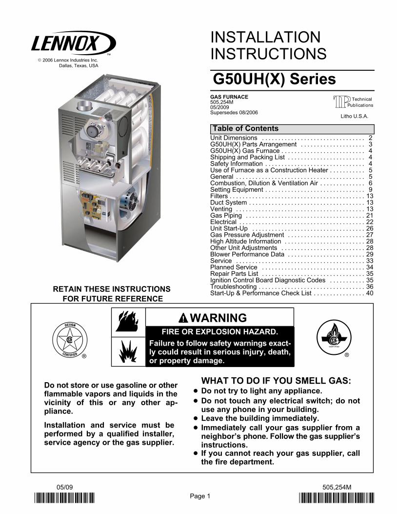
RETAIN THESE INSTRUCTIONS
FOR FUTURE REFERENCE
INSTALLATIONINSTRUCTIONS
G50UH(X) SeriesGAS FURNACE505,254M05/2009Supersedes 08/2006
Table of ContentsUnit Dimensions 2. . . . . . . . . . . . . . . . . . . . . . . . . . . . . . . . G50UH(X) Parts Arrangement 3. . . . . . . . . . . . . . . . . . . . G50UH(X) Gas Furnace 4. . . . . . . . . . . . . . . . . . . . . . . . . . Shipping and Packing List 4. . . . . . . . . . . . . . . . . . . . . . . . Safety Information 4. . . . . . . . . . . . . . . . . . . . . . . . . . . . . . . Use of Furnace as a Construction Heater 5. . . . . . . . . . . General 5. . . . . . . . . . . . . . . . . . . . . . . . . . . . . . . . . . . . . . . . Combustion, Dilution & Ventilation Air 6. . . . . . . . . . . . . . Setting Equipment 9. . . . . . . . . . . . . . . . . . . . . . . . . . . . . . . Filters 13. . . . . . . . . . . . . . . . . . . . . . . . . . . . . . . . . . . . . . . . . . Duct System 13. . . . . . . . . . . . . . . . . . . . . . . . . . . . . . . . . . . . Venting 13. . . . . . . . . . . . . . . . . . . . . . . . . . . . . . . . . . . . . . . . Gas Piping 21. . . . . . . . . . . . . . . . . . . . . . . . . . . . . . . . . . . . . Electrical 22. . . . . . . . . . . . . . . . . . . . . . . . . . . . . . . . . . . . . . . Unit Start−Up 26. . . . . . . . . . . . . . . . . . . . . . . . . . . . . . . . . . . Gas Pressure Adjustment 27. . . . . . . . . . . . . . . . . . . . . . . . High Altitude Information 28. . . . . . . . . . . . . . . . . . . . . . . . . Other Unit Adjustments 28. . . . . . . . . . . . . . . . . . . . . . . . . . Blower Performance Data 29. . . . . . . . . . . . . . . . . . . . . . . . Service 33. . . . . . . . . . . . . . . . . . . . . . . . . . . . . . . . . . . . . . . . Planned Service 34. . . . . . . . . . . . . . . . . . . . . . . . . . . . . . . . Repair Parts List 35. . . . . . . . . . . . . . . . . . . . . . . . . . . . . . . . Ignition Control Board Diagnostic Codes 35. . . . . . . . . . . Troubleshooting 36. . . . . . . . . . . . . . . . . . . . . . . . . . . . . . . . . Start−Up & Performance Check List 40. . . . . . . . . . . . . . . .
WHAT TO DO IF YOU SMELL GAS:Do not store or use gasoline or otherflammable vapors and liquids in thevicinity of this or any other ap-pliance.
Installation and service must beperformed by a qualified installer,service agency or the gas supplier.
� Do not try to light any appliance.
� Do not touch any electrical switch; do notuse any phone in your building.
� Immediately call your gas supplier from aneighbor’s phone. Follow the gas supplier’sinstructions.
� If you cannot reach your gas supplier, callthe fire department.
FIRE OR EXPLOSION HAZARD.
Failure to follow safety warnings exact-ly could result in serious injury, death,or property damage.
WARNING
� Leave the building immediately.
Litho U.S.A.
Page 2505254M 05/2009
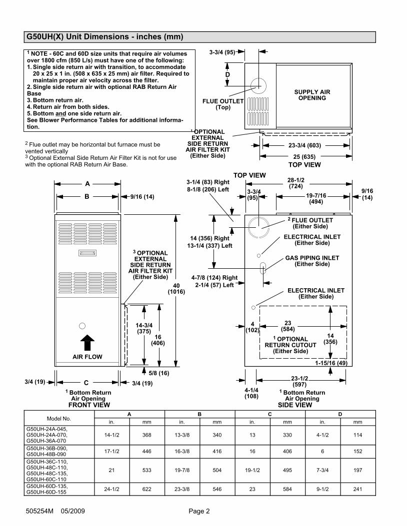
G50UH(X) Unit Dimensions − inches (mm)
1 Bottom ReturnAir Opening
GAS PIPING INLET(Either Side)
1 Bottom ReturnAir Opening
FLUE OUTLET(Top)
ELECTRICAL INLET(Either Side)
ELECTRICAL INLET(Either Side)
SUPPLY AIROPENING
AIR FLOW
FRONT VIEW SIDE VIEW
TOP VIEW
A
B 9/16 (14)
C
D
3/4 (19)3/4 (19)
28−1/2(724)
19−7/16(494)
23−1/2(597)
4−1/4(108)
14 (356) Right
13−1/4 (337) Left
4−7/8 (124) Right
2−1/4 (57) Left40(1016)
3−3/4 (95)
4(102)
1−15/16 (49)
23(584)
14(356)
9/16(14)
3−3/4(95)
3−1/4 (83) Right
8−1/8 (206) Left
2 FLUE OUTLET(Either Side)
TOP VIEW
1 OPTIONALEXTERNAL
SIDE RETURNAIR FILTER KIT
(Either Side)
16(406)
14−3/4(375)
5/8 (16)
3 OPTIONALEXTERNAL
SIDE RETURNAIR FILTER KIT
(Either Side)
23-3/4 (603)
25 (635)
2 Flue outlet may be horizontal but furnace must bevented vertically3 Optional External Side Return Air Filter Kit is not for usewith the optional RAB Return Air Base.
1 NOTE − 60C and 60D size units that require air volumesover 1800 cfm (850 L/s) must have one of the following:1. Single side return air with transition, to accommodate
20 x 25 x 1 in. (508 x 635 x 25 mm) air filter. Required tomaintain proper air velocity across the filter.
2. Single side return air with optional RAB Return AirBase3. Bottom return air.4. Return air from both sides.5. Bottom and one side return air.See Blower Performance Tables for additional informa-tion.
1 OPTIONALRETURN CUTOUT
(Either Side)
Model NoA B C D
Model No.in. mm in. mm in. mm in. mm
G50UH−24A−045,G50UH−24A−070,G50UH−36A−070
14−1/2 368 13−3/8 340 13 330 4−1/2 114
G50UH−36B−090,G50UH−48B−090
17−1/2 446 16−3/8 416 16 406 6 152
G50UH−36C−110,G50UH−48C−110,G50UH−48C−135,G50UH−60C−110
21 533 19−7/8 504 19−1/2 495 7−3/4 197
G50UH−60D−135,G50UH−60D−155
24−1/2 622 23−3/8 546 23 584 9−1/2 241
Page 3 G50UH Series
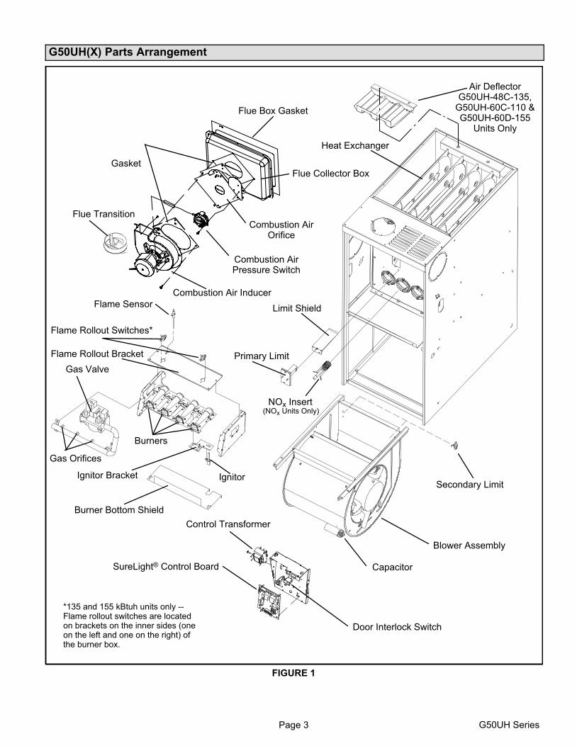
G50UH(X) Parts Arrangement
FIGURE 1
Flue Transition
Combustion Air Inducer
Combustion AirOrifice
Combustion AirPressure Switch
Flue Collector Box
Heat Exchanger
Flame Sensor
Gas Valve
Burners
Ignitor
NOx Insert
Primary Limit
Blower Assembly
Capacitor
Door Interlock Switch
SureLight® Control Board
Control Transformer
Gasket
Flue Box Gasket
Flame Rollout Switches*
Flame Rollout Bracket
Gas Orifices
Ignitor Bracket
Burner Bottom Shield
Limit Shield
Secondary Limit
(NOx Units Only)
Air DeflectorG50UH−48C−135,
G50UH−60C−110 &G50UH−60D−155
Units Only
*135 and 155 kBtuh units only −−Flame rollout switches are locatedon brackets on the inner sides (oneon the left and one on the right) ofthe burner box.
Page 4505254M 05/2009
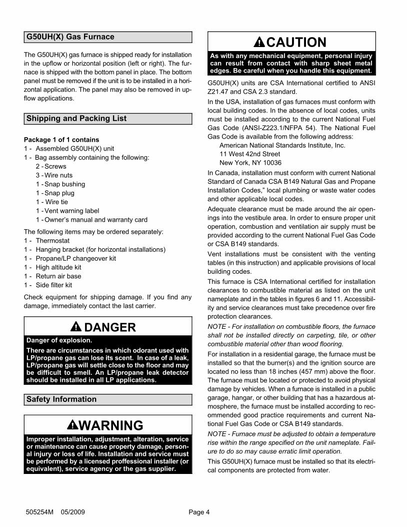
G50UH(X) Gas Furnace
The G50UH(X) gas furnace is shipped ready for installation
in the upflow or horizontal position (left or right). The fur-
nace is shipped with the bottom panel in place. The bottom
panel must be removed if the unit is to be installed in a hori-
zontal application. The panel may also be removed in up-
flow applications.
Shipping and Packing List
Package 1 of 1 contains
1 − Assembled G50UH(X) unit
1 − Bag assembly containing the following:
2 − Screws
3 − Wire nuts
1 − Snap bushing
1 − Snap plug
1 − Wire tie
1 − Vent warning label
1 − Owner’s manual and warranty card
The following items may be ordered separately:
1 − Thermostat
1 − Hanging bracket (for horizontal installations)
1 − Propane/LP changeover kit
1 − High altitude kit
1 − Return air base
1 − Side filter kit
Check equipment for shipping damage. If you find any
damage, immediately contact the last carrier.
DANGERDanger of explosion.
There are circumstances in which odorant used withLP/propane gas can lose its scent. In case of a leak,LP/propane gas will settle close to the floor and maybe difficult to smell. An LP/propane leak detectorshould be installed in all LP applications.
Safety Information
WARNINGImproper installation, adjustment, alteration, serviceor maintenance can cause property damage, person-al injury or loss of life. Installation and service mustbe performed by a licensed proffessional installer (orequivalent), service agency or the gas supplier.
CAUTIONAs with any mechanical equipment, personal injurycan result from contact with sharp sheet metaledges. Be careful when you handle this equipment.
G50UH(X) units are CSA International certified to ANSI
Z21.47 and CSA 2.3 standard.
In the USA, installation of gas furnaces must conform with
local building codes. In the absence of local codes, units
must be installed according to the current National Fuel
Gas Code (ANSI-Z223.1/NFPA 54). The National Fuel
Gas Code is available from the following address:
American National Standards Institute, Inc.
11 West 42nd Street
New York, NY 10036
In Canada, installation must conform with current National
Standard of Canada CSA B149 Natural Gas and Propane
Installation Codes," local plumbing or waste water codes
and other applicable local codes.
Adequate clearance must be made around the air open-
ings into the vestibule area. In order to ensure proper unit
operation, combustion and ventilation air supply must be
provided according to the current National Fuel Gas Code
or CSA B149 standards.
Vent installations must be consistent with the venting
tables (in this instruction) and applicable provisions of local
building codes.
This furnace is CSA International certified for installation
clearances to combustible material as listed on the unit
nameplate and in the tables in figures 6 and 11. Accessibil-
ity and service clearances must take precedence over fire
protection clearances.
NOTE − For installation on combustible floors, the furnace
shall not be installed directly on carpeting, tile, or other
combustible material other than wood flooring.
For installation in a residential garage, the furnace must be
installed so that the burner(s) and the ignition source are
located no less than 18 inches (457 mm) above the floor.
The furnace must be located or protected to avoid physical
damage by vehicles. When a furnace is installed in a public
garage, hangar, or other building that has a hazardous at-
mosphere, the furnace must be installed according to rec-
ommended good practice requirements and current Na-
tional Fuel Gas Code or CSA B149 standards.
NOTE − Furnace must be adjusted to obtain a temperature
rise within the range specified on the unit nameplate. Fail-
ure to do so may cause erratic limit operation.
This G50UH(X) furnace must be installed so that its electri-
cal components are protected from water.
Page 5 G50UH Series
When this furnace is used with cooling units, it shall be
installed in parallel with, or on the upstream side of, cooling
units to avoid condensation in the heating compartment.
With a parallel flow arrangement, a damper (or other
means to control the flow of air) must adequately prevent
chilled air from entering the furnace. If the damper is manu-
ally operated, it must be equipped to prevent operation of
either the heating or the cooling unit, unless it is in the full
HEAT or COOL setting.
When installed, this furnace must be electrically grounded
according to local codes. In addition, in the United States,
installation must conform with the current National Electric
Code, ANSI/NFPA No. 70. The National Electric Code
(ANSI/NFPA No. 70) is available from the following ad-
dress:
National Fire Protection Association
1 Battery March Park
Quincy, MA 02269
In Canada, all electrical wiring and grounding for the unit
must be installed according to the current regulations of the
Canadian Electrical Code Part I (CSA Standard C22.1)
and/or local codes.
NOTE − This furnace is designed for a minimum continuous
return air temperature of 60°F (16°C) or an intermittent op-
eration down to 55°F (13°C) dry bulb for cases where a
night setback thermostat is used. Return air temperature
must not exceed 85°F (29°C) dry bulb.
The G50UH(X) furnace may be installed in alcoves, clos-
ets, attics, basements, garages, and utility rooms in the up-
flow or horizontal position.
This furnace design has not been CSA International certi-
fied for installation in mobile homes, recreational vehicles,
or outdoors.
Use of Furnace as a Construction Heater
Lennox does not recommend the use of G50UH units as a
construction heater during any phase of construction. Very
low return air temperatures, harmful vapors and operation
of the unit with clogged or misplaced filters will damage the
unit.
G50UH units may be used for heating of buildings or struc-
tures under construction, if the following conditions are
met:
� The vent system must be permanently installed per
these installation instructions.
� A room thermostat must control the furnace. The use of
fixed jumpers that will provide continuous heating is not
allowed.
� The return air duct must be provided and sealed to the
furnace.
� Return air temperature range between 60°F (16°C) and
80°F (27°C) must be maintained.
� Air filters must be installed in the system and must be
maintained during construction.
� Air filters must be replaced upon construction comple-
tion.
� The input rate and temperature rise must be set per the
furnace rating plate.
� One hundred percent (100%) outdoor air must be pro-
vided for combustion air requirements during construc-
tion. Temporary ducting may supply outdoor air to the
furnace. Do not connect duct directly to the furnace.
Size the temporary duct following these instructions in
section for Combustion, Dilution and Ventilation Air in a
confined space with air from outside.
� The furnace heat exchanger, components, duct sys-
tem, air filters and evaporator coils must be thoroughly
cleaned following final construction clean−up.
� All furnace operating conditions (including ignition, in-
put rate, temperature rise and venting) must be verified
according to these installation instructions.
NOTE − The Commonwealth of Massachusetts stipu-
lates these additional requirements:
� Gas furnaces shall be installed by a licensed plumb-
er or gas fitter only.
� The gas cock must be �T handle" type.
� When a furnace is installed in an attic, the passage-
way to and service area surrounding the equipment
shall be floored.
General
These instructions are intended as a general guide and do
not supersede local codes in any way. Consult authorities
having jurisdiction before installation.
In addition to the requirements outlined previously, the fol-
lowing general recommendations must be considered
when installing a G50UH(X) furnace:
� Place the furnace as close to the center of the air dis-
tribution system as possible. The furnace should also be
located close to the chimney or vent termination point.
� Do not install the furnace where drafts might blow direct-
ly into it. This could cause improper combustion and un-
safe operation.
� Do not block the furnace combustion air openings with
clothing, boxes, doors, etc. Air is needed for proper
combustion and safe unit operation.
� When the furnace is installed in an attic or other insu-
lated space, keep insulation away from the furnace.
Page 6505254M 05/2009
WARNINGProduct contains fiberglass wool.
Disturbing the insulation in this product duringinstallation, maintenance, or repair will expose youto fiberglass wool. Breathing this may cause lungcancer. (Fiberglass wool is known to the State of Cal-ifornia to cause cancer.)
Fiberglass wool may also cause respiratory, skin,and eye irritation.
To reduce exposure to this substance or for furtherinformation, consult material safety data sheetsavailable from address shown below, or contact yoursupervisor.
Lennox Industries Inc.P.O. Box 799900Dallas, TX 75379−9900
Combustion, Dilution & Ventilation Air
In the past, there was no problem in bringing in sufficient
outdoor air for combustion. Infiltration provided all the air
that was needed. In today’s homes, tight construction prac-
tices make it necessary to bring in air from outside for com-
bustion. Take into account that exhaust fans, appliance
vents, chimneys, and fireplaces force additional air that
could be used for combustion out of the house. Unless out-
side air is brought into the house for combustion, negative
pressure (outside pressure is greater than inside pressure)
will build to the point that a downdraft can occur in the fur-
nace vent pipe or chimney. As a result, combustion gases
enter the living space creating a potentially dangerous situ-
ation.
In the absence of local codes concerning air for combus-
tion and ventilation, use the guidelines and procedures in
this section to install G50UH(X) furnaces to ensure efficient
and safe operation. You must consider combustion air
needs and requirements for exhaust vents and gas piping.
A portion of this information has been reprinted with per-
mission from the National Fuel Gas Code (ANSI-Z223.1).
This reprinted material is not the complete and official posi-
tion of the ANSI on the referenced subject, which is repre-
sented only by the standard in its entirety.
In Canada, refer to the standard CSA B149 installation
codes.
CAUTIONDo not install the furnace in a corrosive or contami-nated atmosphere. Meet all combustion and ventila-tion air requirements, as well as all local codes.
CAUTIONInsufficient combustion air can cause headaches,nausea, dizziness or asphyxiation. It will also causeexcess water in the heat exchanger resulting in rust-ing and premature heat exchanger failure. Excessiveexposure to contaminated combustion air will resultin safety and performance related problems. Avoidexposure to the following substances in the com-bustion air supply:
Permanent wave solutionsChlorinated waxes and cleanersChlorine base swimming pool chemicalsWater softening chemicalsDe-icing salts or chemicalsCarbon tetrachlorideHalogen type refrigerantsCleaning solvents (such as perchloroethylene)Printing inks, paint removers, varnishes, etc.Hydrochloric acidCements and gluesAntistatic fabric softeners for clothes dryersMasonry acid washing materials
All gas-fired appliances require air for the combustion pro-
cess. If sufficient combustion air is not available, the fur-
nace or other appliances will operate inefficiently and un-
safely. Enough air must be provided to meet the needs of
all fuel-burning appliances and appliances such as ex-
haust fans which force air out of the house. When fire-
places, exhaust fans, or clothes dryers are used at the
same time as the furnace, much more air is necessary to
ensure proper combustion and to prevent a downdraft. In-
sufficient air causes incomplete combustion which can re-
sult in carbon monoxide.
In addition to providing combustion air, fresh outdoor air di-
lutes contaminants in the indoor air. These contaminants
may include bleaches, adhesives, detergents, solvents
and other contaminants which can corrode furnace compo-
nents.
The requirements for providing air for combustion and ven-
tilation depend largely on whether the furnace is installed in
an unconfined or a confined space.
Unconfined Space
An unconfined space is an area such as a basement or
large equipment room with a volume greater than 50 cubic
feet (1.42 m3) per 1,000 Btu (.29 kW) per hour of the com-
bined input rating of all appliances installed in that space.
This space also includes adjacent rooms which are not
separated by a door. Though an area may appear to be un-
confined, it might be necessary to bring in outdoor air for
combustion if the structure does not provide enough air by
Page 7 G50UH Series
infiltration. If the furnace is located in a building of tight
construction with weather stripping and caulking around
the windows and doors, follow the procedures in the air
from outside section.
Confined Space
A confined space is an area with a volume less than 50 cu-
bic feet (1.42 m3) per 1,000 Btu (.29 kW) per hour of the
combined input rating of all appliances installed in that
space. This definition includes furnace closets or small
equipment rooms.
When the furnace is installed so that supply ducts carry air
circulated by the furnace to areas outside the space con-
taining the furnace, the return air must be handled by ducts
which are sealed to the furnace casing and which terminate
outside the space containing the furnace. This is especially
important when the furnace is mounted on a platform in a
confined space such as a closet or small equipment room.
Even a small leak around the base of the unit at the platform
or at the return air duct connection can cause a potentially
dangerous negative pressure condition. Air for combustion
and ventilation can be brought into the confined space ei-
ther from inside the building or from outside.
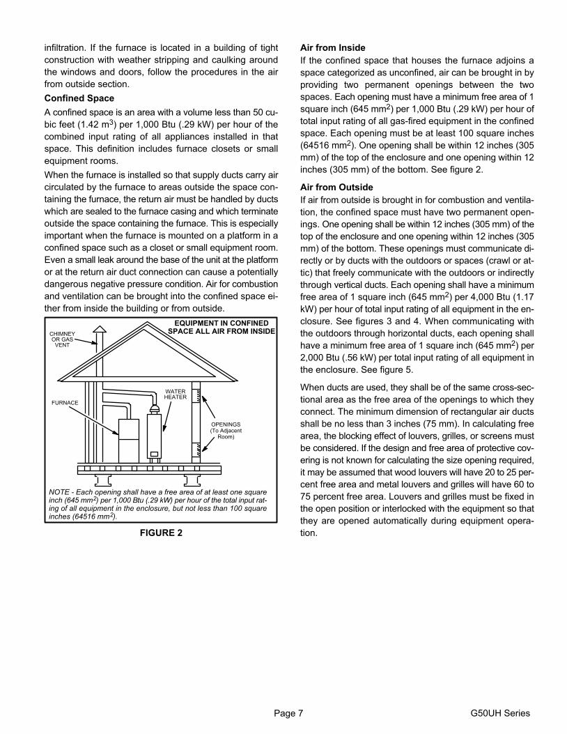
EQUIPMENT IN CONFINEDSPACE ALL AIR FROM INSIDECHIMNEY
OR GASVENT
FURNACE
WATERHEATER
OPENINGS(To Adjacent
Room)
NOTE − Each opening shall have a free area of at least one squareinch (645 mm2) per 1,000 Btu (.29 kW) per hour of the total input rat-ing of all equipment in the enclosure, but not less than 100 squareinches (64516 mm2).
FIGURE 2
Air from Inside
If the confined space that houses the furnace adjoins a
space categorized as unconfined, air can be brought in by
providing two permanent openings between the two
spaces. Each opening must have a minimum free area of 1
square inch (645 mm2) per 1,000 Btu (.29 kW) per hour of
total input rating of all gas−fired equipment in the confined
space. Each opening must be at least 100 square inches
(64516 mm2). One opening shall be within 12 inches (305
mm) of the top of the enclosure and one opening within 12
inches (305 mm) of the bottom. See figure 2.
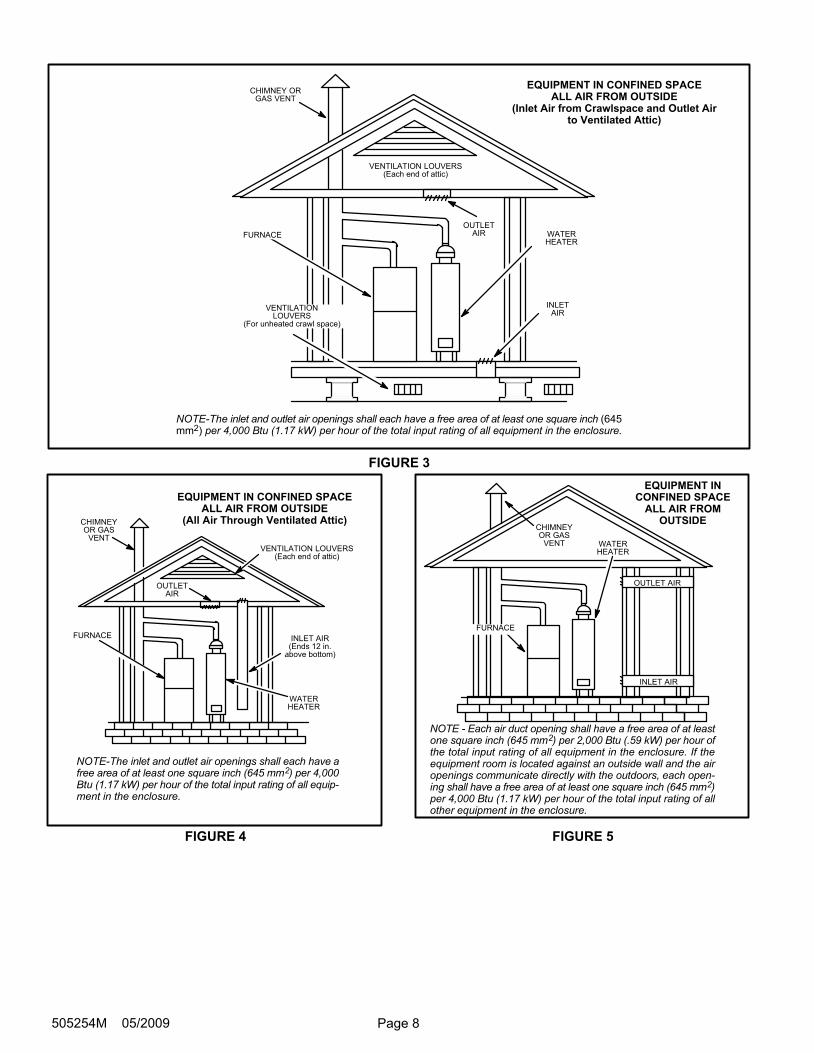
Air from Outside
If air from outside is brought in for combustion and ventila-
tion, the confined space must have two permanent open-
ings. One opening shall be within 12 inches (305 mm) of the
top of the enclosure and one opening within 12 inches (305
mm) of the bottom. These openings must communicate di-
rectly or by ducts with the outdoors or spaces (crawl or at-
tic) that freely communicate with the outdoors or indirectly
through vertical ducts. Each opening shall have a minimum
free area of 1 square inch (645 mm2) per 4,000 Btu (1.17
kW) per hour of total input rating of all equipment in the en-
closure. See figures 3 and 4. When communicating with
the outdoors through horizontal ducts, each opening shall
have a minimum free area of 1 square inch (645 mm2) per
2,000 Btu (.56 kW) per total input rating of all equipment in
the enclosure. See figure 5.
When ducts are used, they shall be of the same cross−sec-
tional area as the free area of the openings to which they
connect. The minimum dimension of rectangular air ducts
shall be no less than 3 inches (75 mm). In calculating free
area, the blocking effect of louvers, grilles, or screens must
be considered. If the design and free area of protective cov-
ering is not known for calculating the size opening required,
it may be assumed that wood louvers will have 20 to 25 per-
cent free area and metal louvers and grilles will have 60 to
75 percent free area. Louvers and grilles must be fixed in
the open position or interlocked with the equipment so that
they are opened automatically during equipment opera-
tion.
Page 8505254M 05/2009
EQUIPMENT IN CONFINED SPACEALL AIR FROM OUTSIDE
(Inlet Air from Crawlspace and Outlet Airto Ventilated Attic)
NOTE−The inlet and outlet air openings shall each have a free area of at least one square inch (645mm2) per 4,000 Btu (1.17 kW) per hour of the total input rating of all equipment in the enclosure.
VENTILATION LOUVERS(Each end of attic)
OUTLETAIR WATER
HEATER
INLETAIR
CHIMNEY ORGAS VENT
FURNACE
VENTILATIONLOUVERS
(For unheated crawl space)
FIGURE 3
EQUIPMENT IN CONFINED SPACEALL AIR FROM OUTSIDE
(All Air Through Ventilated Attic)
NOTE−The inlet and outlet air openings shall each have afree area of at least one square inch (645 mm2) per 4,000Btu (1.17 kW) per hour of the total input rating of all equip-ment in the enclosure.
CHIMNEYOR GAS
VENT
WATERHEATER
OUTLETAIR
VENTILATION LOUVERS(Each end of attic)
INLET AIR(Ends 12 in.
above bottom)
FURNACE
FIGURE 4
EQUIPMENT INCONFINED SPACE
ALL AIR FROMOUTSIDE
OUTLET AIR
INLET AIR
WATERHEATER
CHIMNEYOR GAS
VENT
NOTE − Each air duct opening shall have a free area of at leastone square inch (645 mm2) per 2,000 Btu (.59 kW) per hour ofthe total input rating of all equipment in the enclosure. If theequipment room is located against an outside wall and the airopenings communicate directly with the outdoors, each open-ing shall have a free area of at least one square inch (645 mm2)per 4,000 Btu (1.17 kW) per hour of the total input rating of allother equipment in the enclosure.
FURNACE
FIGURE 5
Page 9 G50UH Series
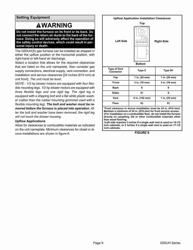
Setting Equipment
WARNINGDo not install the furnace on its front or its back. Donot connect the return air ducts to the back of the fur-nace. Doing so will adversely affect the operation ofthe safety control devices, which could result in per-sonal injury or death.
The G50UH(X) gas furnace can be installed as shipped in
either the upflow position or the horizontal position, with
right-hand or left-hand air discharge.
Select a location that allows for the required clearances
that are listed on the unit nameplate. Also consider gas
supply connections, electrical supply, vent connection, and
installation and service clearances [24 inches (610 mm) at
unit front]. The unit must be level.
NOTE − 1/3 hp blower motors are equipped with four flex-
ible mounting legs. 1/2 hp blower motors are equipped with
three flexible legs and one rigid leg. The rigid leg is
equipped with a shipping bolt and a flat white plastic wash-
er (rather than the rubber mounting grommet used with a
flexible mounting leg). The bolt and washer must be re-
moved before the furnace is placed into operation. Af-
ter the bolt and washer have been removed, the rigid leg
will not touch the blower housing.
Upflow Applications
Allow for clearances to combustible materials as indicated
on the unit nameplate. Minimum clearances for closet or al-
cove installations are shown in figure 6.
Upflow Application Installation Clearances
Top
Bottom
Left Side Right Side
Type of VentConnector
Type C Type B1
Top 1 in. (25 mm) 1 in. (25 mm)
*Front 3 in. (76 mm) 3 in. (76 mm)
Back 0 0
Sides 0† 0
Vent 6 in. (152 mm) 1 in. (25 mm)
Floor 0‡ 0‡
*Front clearance in alcove installation must be 24 in. (610 mm).Maintain a minimum of 24 in. (610 mm) for front service access.‡For installation on a combustible floor, do not install the furnacedirectly on carpeting, tile or other combustible materials otherthan wood flooring.†Left side requires 3 inches if a single wall vent is used on 14−1/2inch cabinets, or 2 inches if a single wall vent is used on 17−1/2inch cabinets.
FIGURE 6
Page 10505254M 05/2009
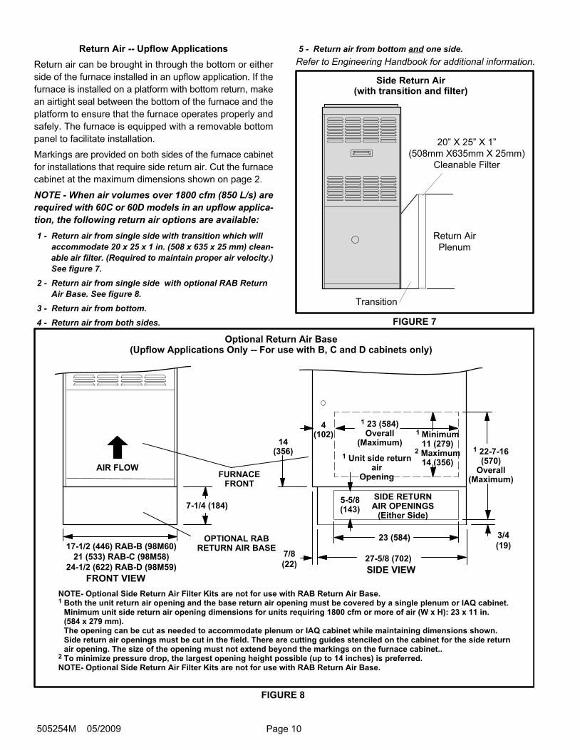
Return Air −− Upflow Applications
Return air can be brought in through the bottom or either
side of the furnace installed in an upflow application. If the
furnace is installed on a platform with bottom return, make
an airtight seal between the bottom of the furnace and the
platform to ensure that the furnace operates properly and
safely. The furnace is equipped with a removable bottom
panel to facilitate installation.
Markings are provided on both sides of the furnace cabinet
for installations that require side return air. Cut the furnace
cabinet at the maximum dimensions shown on page 2.
NOTE − When air volumes over 1800 cfm (850 L/s) are
required with 60C or 60D models in an upflow applica-
tion, the following return air options are available:
1 − Return air from single side with transition which will
accommodate 20 x 25 x 1 in. (508 x 635 x 25 mm) clean-
able air filter. (Required to maintain proper air velocity.)
See figure 7.
2 − Return air from single side with optional RAB Return
Air Base. See figure 8.
3 − Return air from bottom.
4 − Return air from both sides.
5 − Return air from bottom and one side.
Refer to Engineering Handbook for additional information.
Side Return Air(with transition and filter)
FIGURE 7
Return Air
Plenum
Transition
20" X 25" X 1"
(508mm X635mm X 25mm)
Cleanable Filter
Optional Return Air Base(Upflow Applications Only −− For use with B, C and D cabinets only)
NOTE− Optional Side Return Air Filter Kits are not for use with RAB Return Air Base.1 Both the unit return air opening and the base return air opening must be covered by a single plenum or IAQ cabinet.
Minimum unit side return air opening dimensions for units requiring 1800 cfm or more of air (W x H): 23 x 11 in. (584 x 279 mm).The opening can be cut as needed to accommodate plenum or IAQ cabinet while maintaining dimensions shown.Side return air openings must be cut in the field. There are cutting guides stenciled on the cabinet for the side return air opening. The size of the opening must not extend beyond the markings on the furnace cabinet..
2 To minimize pressure drop, the largest opening height possible (up to 14 inches) is preferred.NOTE− Optional Side Return Air Filter Kits are not for use with RAB Return Air Base.
1 Unit side returnair
Opening
FRONT VIEWSIDE VIEW
27−5/8 (702)
4(102)
1 23 (584)Overall
(Maximum)
OPTIONAL RABRETURN AIR BASE
23 (584)
7−1/4 (184)
7/8
(22)
3/4
(19)
1 22−7−16(570)
Overall(Maximum)
SIDE RETURNAIR OPENINGS
(Either Side)
FURNACEFRONT
14(356)
AIR FLOW
5−5/8(143)
1 Minimum11 (279)
2 Maximum14 (356)
21 (533) RAB−C (98M58)
24−1/2 (622) RAB−D (98M59)
17−1/2 (446) RAB−B (98M60)
FIGURE 8
Page 11 G50UH Series
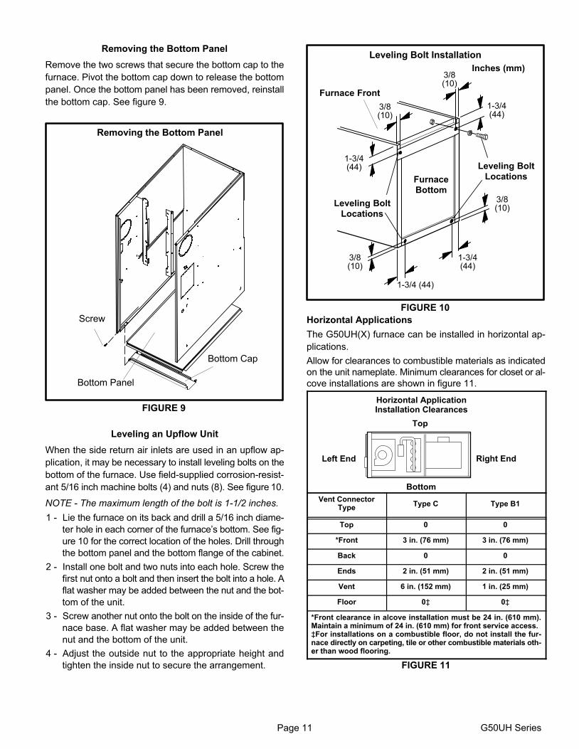
Removing the Bottom Panel
Remove the two screws that secure the bottom cap to the
furnace. Pivot the bottom cap down to release the bottom
panel. Once the bottom panel has been removed, reinstall
the bottom cap. See figure 9.
Removing the Bottom Panel
FIGURE 9
Screw
Bottom Panel
Bottom Cap
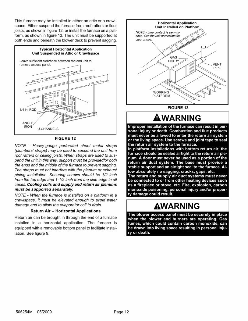
Leveling an Upflow Unit
When the side return air inlets are used in an upflow ap-
plication, it may be necessary to install leveling bolts on the
bottom of the furnace. Use field−supplied corrosion−resist-
ant 5/16 inch machine bolts (4) and nuts (8). See figure 10.
NOTE − The maximum length of the bolt is 1−1/2 inches.
1 − Lie the furnace on its back and drill a 5/16 inch diame-
ter hole in each corner of the furnace’s bottom. See fig-
ure 10 for the correct location of the holes. Drill through
the bottom panel and the bottom flange of the cabinet.
2 − Install one bolt and two nuts into each hole. Screw the
first nut onto a bolt and then insert the bolt into a hole. A
flat washer may be added between the nut and the bot-
tom of the unit.
3 − Screw another nut onto the bolt on the inside of the fur-
nace base. A flat washer may be added between the
nut and the bottom of the unit.
4 − Adjust the outside nut to the appropriate height and
tighten the inside nut to secure the arrangement.
FIGURE 10
1−3/4(44)
1−3/4(44)
3/8(10)
1−3/4 (44)
3/8(10)
3/8(10)
3/8(10)
1−3/4(44)
Leveling Bolt Installation
Leveling BoltLocations
Leveling BoltLocations
Inches (mm)
Furnace Front
FurnaceBottom
Horizontal Applications
The G50UH(X) furnace can be installed in horizontal ap-
plications.
Allow for clearances to combustible materials as indicated
on the unit nameplate. Minimum clearances for closet or al-
cove installations are shown in figure 11.
Horizontal ApplicationInstallation Clearances
Top
Bottom
Left End Right End
Vent ConnectorType
Type C Type B1
Top 0 0
*Front 3 in. (76 mm) 3 in. (76 mm)
Back 0 0
Ends 2 in. (51 mm) 2 in. (51 mm)
Vent 6 in. (152 mm) 1 in. (25 mm)
Floor 0‡ 0‡
*Front clearance in alcove installation must be 24 in. (610 mm).Maintain a minimum of 24 in. (610 mm) for front service access.‡For installations on a combustible floor, do not install the fur-nace directly on carpeting, tile or other combustible materials oth-er than wood flooring.
FIGURE 11
Page 12505254M 05/2009
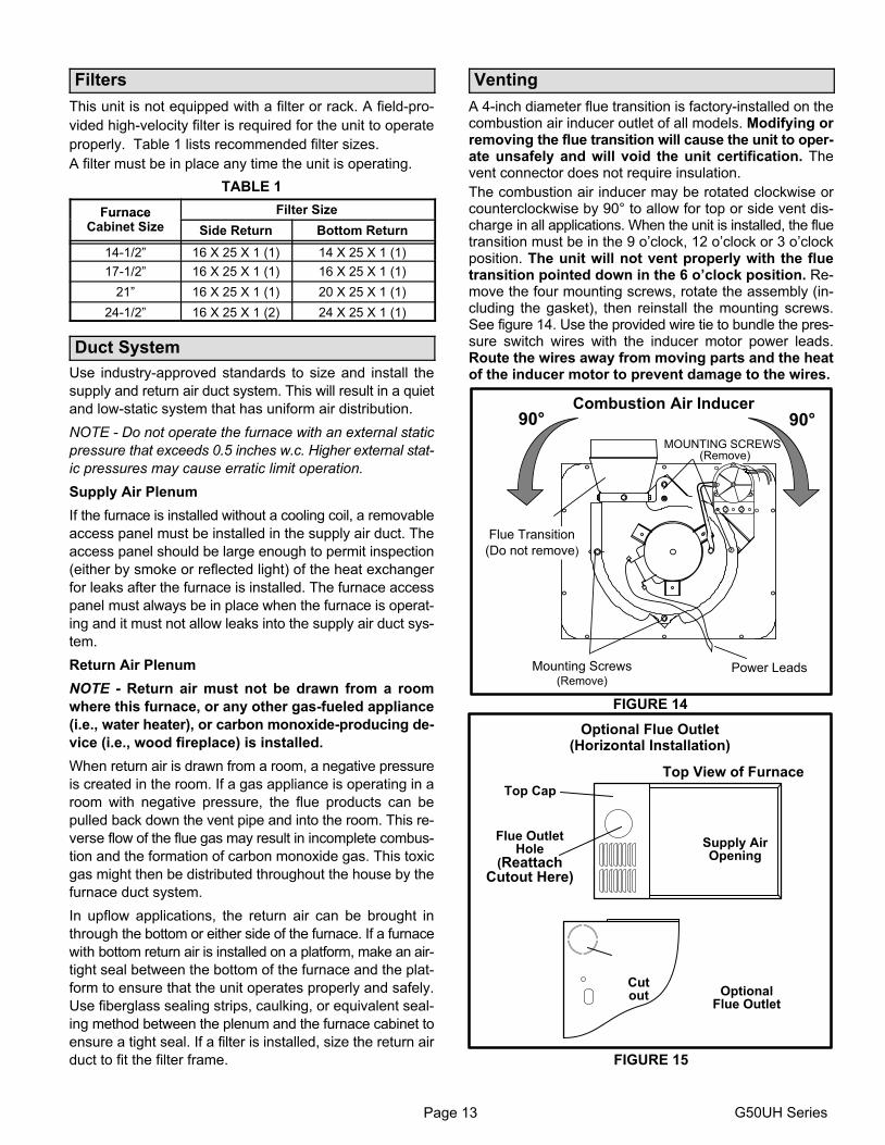
This furnace may be installed in either an attic or a crawl-
space. Either suspend the furnace from roof rafters or floor
joists, as shown in figure 12, or install the furnace on a plat-
form, as shown in figure 13. The unit must be supported at
both ends and beneath the blower deck to prevent sagging.
Typical Horizontal ApplicationUnit Suspended in Attic or Crawlspace
Leave sufficient clearance between rod and unit toremove access panel.
FIGURE 12
1/4 in. ROD
ANGLEIRON
U−CHANNELS
NOTE − Heavy−gauge perforated sheet metal straps
(plumbers’ straps) may be used to suspend the unit from
roof rafters or ceiling joists. When straps are used to sus-
pend the unit in this way, support must be providedfor both
the ends and the middle of the furnace to prevent sagging.
The straps must not interfere with the plenum or exhaust
piping installation. Securing screws should be 1/2 inch
from the top edge and 1−1/2 inch from the side edge in all
cases. Cooling coils and supply and return air plenums
must be supported separately.
NOTE − When the furnace is installed on a platform in a
crawlspace, it must be elevated enough to avoid water
damage and to allow the evaporator coil to drain.
Return Air −− Horizontal Applications
Return air can be brought in through the end of a furnace
installed in a horizontal application. The furnace is
equipped with a removable bottom panel to facilitate instal-
lation. See figure 9.
Horizontal ApplicationUnit Installed on Platform
WORKINGPLATFORM
GASENTRY
VENTPIPE
NOTE − Line contact is permis-sible. See the unit nameplate forclearances.
FIGURE 13
WARNINGImproper installation of the furnace can result in per-sonal injury or death. Combustion and flue productsmust never be allowed to enter the return air systemor the living space. Use screws and joint tape to sealthe return air system to the furnace.In platform installations with bottom return air, thefurnace should be sealed airtight to the return air ple-num. A door must never be used as a portion of thereturn air duct system. The base must provide astable support and an airtight seal to the furnace. Al-low absolutely no sagging, cracks, gaps, etc.The return and supply air duct systems must neverbe connected to or from other heating devices suchas a fireplace or stove, etc. Fire, explosion, carbonmonoxide poisoning, personal injury and/or proper-ty damage could result.
WARNINGThe blower access panel must be securely in placewhen the blower and burners are operating. Gasfumes, which could contain carbon monoxide, canbe drawn into living space resulting in personal inju-ry or death.
Page 13 G50UH Series
Filters
This unit is not equipped with a filter or rack. A field−pro-
vided high−velocity filter is required for the unit to operate
properly. Table 1 lists recommended filter sizes.
A filter must be in place any time the unit is operating.
TABLE 1
Furnace Filter SizeFurnaceCabinet Size Side Return Bottom Return
14−1/2" 16 X 25 X 1 (1) 14 X 25 X 1 (1)
17−1/2" 16 X 25 X 1 (1) 16 X 25 X 1 (1)
21" 16 X 25 X 1 (1) 20 X 25 X 1 (1)
24−1/2" 16 X 25 X 1 (2) 24 X 25 X 1 (1)
Duct System
Use industry-approved standards to size and install the
supply and return air duct system. This will result in a quiet
and low-static system that has uniform air distribution.
NOTE − Do not operate the furnace with an external static
pressure that exceeds 0.5 inches w.c. Higher external stat-
ic pressures may cause erratic limit operation.
Supply Air Plenum
If the furnace is installed without a cooling coil, a removable
access panel must be installed in the supply air duct. The
access panel should be large enough to permit inspection
(either by smoke or reflected light) of the heat exchanger
for leaks after the furnace is installed. The furnace access
panel must always be in place when the furnace is operat-
ing and it must not allow leaks into the supply air duct sys-
tem.
Return Air Plenum
NOTE − Return air must not be drawn from a room
where this furnace, or any other gas−fueled appliance
(i.e., water heater), or carbon monoxide−producing de-
vice (i.e., wood fireplace) is installed.
When return air is drawn from a room, a negative pressure
is created in the room. If a gas appliance is operating in a
room with negative pressure, the flue products can be
pulled back down the vent pipe and into the room. This re-
verse flow of the flue gas may result in incomplete combus-
tion and the formation of carbon monoxide gas. This toxic
gas might then be distributed throughout the house by the
furnace duct system.
In upflow applications, the return air can be brought in
through the bottom or either side of the furnace. If a furnace
with bottom return air is installed on a platform, make an air-
tight seal between the bottom of the furnace and the plat-
form to ensure that the unit operates properly and safely.
Use fiberglass sealing strips, caulking, or equivalent seal-
ing method between the plenum and the furnace cabinet to
ensure a tight seal. If a filter is installed, size the return air
duct to fit the filter frame.
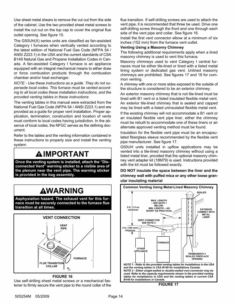
Venting
A 4−inch diameter flue transition is factory-installed on thecombustion air inducer outlet of all models. Modifying orremoving the flue transition will cause the unit to oper-ate unsafely and will void the unit certification. Thevent connector does not require insulation.
The combustion air inducer may be rotated clockwise orcounterclockwise by 90° to allow for top or side vent dis-charge in all applications. When the unit is installed, the fluetransition must be in the 9 o’clock, 12 o’clock or 3 o’clockposition. The unit will not vent properly with the fluetransition pointed down in the 6 o’clock position. Re-move the four mounting screws, rotate the assembly (in-cluding the gasket), then reinstall the mounting screws.See figure 14. Use the provided wire tie to bundle the pres-sure switch wires with the inducer motor power leads.Route the wires away from moving parts and the heatof the inducer motor to prevent damage to the wires.
FIGURE 14
Combustion Air Inducer
Mounting Screws
MOUNTING SCREWS
90° 90°
(Remove)
(Remove)Power Leads
Flue Transition
(Do not remove)
Flue OutletHole
(ReattachCutout Here)
Supply AirOpening
Top View of Furnace
Top Cap
Cutout Optional
Flue Outlet
Optional Flue Outlet(Horizontal Installation)
FIGURE 15
Page 14505254M 05/2009
Use sheet metal shears to remove the cut out from the side
of the cabinet. Use the two provided sheet metal screws to
install the cut out on the top cap to cover the original flue
outlet opening. See figure 15.
The G50UH(X) series units are classified as fan−assisted
Category I furnaces when vertically vented according to
the latest edition of National Fuel Gas Code (NFPA 54 /
ANSI Z223.1) in the USA and the current standards of CSA
B149 Natural Gas and Propane Installation Codes in Can-
ada. A fan−assisted Category I furnace is an appliance
equipped with an integral mechanical means to either draw
or force combustion products through the combustion
chamber and/or heat exchanger.
NOTE − Use these instructions as a guide. They do not su-
persede local codes. This furnace must be vented accord-
ing to all local codes these installation instructions, and the
provided venting tables in these instructions
The venting tables in this manual were extracted from the
National Fuel Gas Code (NFPA 54 / ANSI Z223.1) and are
provided as a guide for proper vent installation. Proper ap-
plication, termination, construction and location of vents
must conform to local codes having jurisdiction. In the ab-
sence of local codes, the NFGC serves as the defining doc-
ument.
Refer to the tables and the venting information contained in
these instructions to properly size and install the venting
system.
IMPORTANTOnce the venting system is installed, attach the �Dis-connected Vent" warning sticker to a visible area ofthe plenum near the vent pipe. The warning stickeris provided in the bag assembly.
WARNINGAsphyxiation hazard. The exhaust vent for this fur-nace must be securely connected to the furnace fluetransition at all times.
FLUE TRANSITIONCOLLAR
VENT CONNECTION
VENTPIPE
FURNACE
FIGURE 16Use self−drilling sheet metal screws or a mechanical fas-tener to firmly secure the vent pipe to the round collar of the
flue transition. If self−drilling screws are used to attach thevent pipe, it is recommended that three be used. Drive oneself−drilling screw through the front and one through eachside of the vent pipe and collar. See figure 16.
Install the first vent connector elbow at a minimum of sixinches (152 mm) from the furnace vent outlet.
Venting Using a Masonry Chimney
The following additional requirements apply when a linedmasonry chimney is used to vent this furnace.
Masonry chimneys used to vent Category I central fur-naces must be either tile-lined or lined with a listed metallining system or dedicated gas vent. Unlined masonrychimneys are prohibited. See figures 17 and 18 for com-mon venting.
A chimney with one or more sides exposed to the outside ofthe structure is considered to be an exterior chimney.
An exterior masonry chimney that is not tile−lined must be
lined with B1 vent or a listed insulated flexible metal vent.
An exterior tile−lined chimney that is sealed and capped
may be lined with a listed uninsulated flexible metal vent.
If the existing chimney will not accommodate a B1 vent or
an insulated flexible vent pipe liner, either the chimney
must be rebuilt to accommodate one of these liners or an
alternate approved venting method must be found.
Insulation for the flexible vent pipe must be an encapsu-
lated fiberglass sleeve recommended by the flexible vent
pipe manufacturer. See figure 17.
G50UH units installed in upflow applications may bevented into a tile−lined masonry chimney without using alisted metal liner, provided that the optional masonry chim-ney vent adapter kit (18M79) is used. Instructions providedwith the kit must be followed exactly.
DO NOT insulate the space between the liner and the
chimney wall with puffed mica or any other loose gran-
ular insulating material
Common Venting Using Metal−Lined Masonry Chimney
4 in. (102 mm)minimum
MIN. LENGTH −− ASSHORT AS PRACTICAL
MAX. LENGTH−− SEE NOTE 1
BELOW.
SEALED
PERMANENTLYSEALED FIREPLACE
OPENING
EXTERIORCHIMNEY WITH
METALLINER
VENT CONNECTORSEE NOTE 2
NOTE 1 − Refer to the provided venting tables for installations in the USAand the venting tables in CSA B149 for installations Canada.NOTE 2 − Either single-walled or double-walled vent connector may beused. Refer to the capacity requirements shown in the provided ventingtables for installations in USA and the venting tables in current CSAB149 for installations in Canada.
OTHERAPPLIANCE
FURNACE
FIGURE 17
5 ft. (1.5 m)minimum
Page 15 G50UH Series
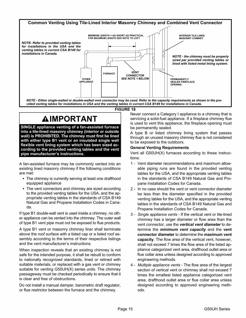
Common Venting Using Tile−Lined Interior Masonry Chimney and Combined Vent Connector
MINIMUM LENGTH = AS SHORT AS PRACTICAL. FOR MAXIMUM LENGTH SEE NOTE TO LEFT
INTERIOR TILE−LINEDMASONRY CHIMNEY
NOTE − the chimney must be properlysized per provided venting tables orlined with listed metal lining system.
PERMANENTLYSEALED FIREPLACEOPENING
VENTCONNECTOR
SEE NOTE 1 BELOW
NOTE − Either single-walled or double-walled vent connector may be used. Refer to the capacity requirements as shown in the pro-vided venting tables for installations in USA and the venting tables in current CSA B149 for installations in Canada.
NOTE− Refer to provided venting tablesfor installations in the USA and theventing tables in current CSA B149 forinstallations in Canada.
FURNACE
OTHERAPPLIANCE
FIGURE 18
IMPORTANTSINGLE appliance venting of a fan-assisted furnaceinto a tile-lined masonry chimney (interior or outsidewall) is PROHIBITED. The chimney must first be linedwith either type B1 vent or an insulated single wallflexible vent lining system which has been sized ac-cording to the provided venting tables and the ventpipe manufacturer’s instructions.
A fan−assisted furnace may be commonly vented into anexisting lined masonry chimney if the following conditionsare met:
� The chimney is currently serving at least one drafthoodequipped appliance
� The vent connectors and chimney are sized accordingto the provided venting tables for the USA, and the ap-propriate venting tables in the standards of CSA B149Natural Gas and Propane Installation Codes in Cana-da.
If type B1 double-wall vent is used inside a chimney, no oth-
er appliance can be vented into the chimney. The outer wall
of type B1 vent pipe must not be exposed to flue products.
A type B1 vent or masonry chimney liner shall terminate
above the roof surface with a listed cap or a listed roof as-
sembly according to the terms of their respective listings
and the vent manufacturer’s instructions.
When inspection reveals that an existing chimney is not
safe for the intended purpose, it shall be rebuilt to conform
to nationally recognized standards, lined or relined with
suitable materials, or replaced with a gas vent or chimney
suitable for venting G50UH(X) series units. The chimney
passageway must be checked periodically to ensure that it
is clear and free of obstructions.
Do not install a manual damper, barometric draft regulator,
or flue restrictor between the furnace and the chimney.
Never connect a Category I appliance to a chimney that isservicing a solid−fuel appliance. If a fireplace chimney flueis used to vent this appliance, the fireplace opening mustbe permanently sealed.
A type B or listed chimney lining system that passesthrough an unused masonry chimney flue is not consideredto be exposed to the outdoors.
General Venting Requirements
Vent all G50UH(X) furnaces according to these instruc-
tions:
1 − Vent diameter recommendations and maximum allow-
able piping runs are found in the provided venting
tables for the USA, and the appropriate venting tables
in the standards of CSA B149 Natural Gas and Pro-
pane Installation Codes for Canada.
2 − In no case should the vent or vent connector diameter
be less than the diameter specified in the provided
venting tables for the USA, and the appropriate venting
tables in the standards of CSA B149 Natural Gas and
Propane Installation Codes for Canada.
3 − Single appliance vents − If the vertical vent or tile-lined
chimney has a larger diameter or flow area than the
vent connector, use the vertical vent diameter to de-
termine the minimum vent capacity and the vent
connector diameter to determine the maximum vent
capacity. The flow area of the vertical vent, however,
shall not exceed 7 times the flow area of the listed ap-
pliance categorized vent area, drafthood outlet area or
flue collar area unless designed according to approved
engineering methods.
4 − Multiple appliance vents − The flow area of the largest
section of vertical vent or chimney shall not exceed 7
times the smallest listed appliance categorized vent
area, drafthood outlet area or flue collar area unless
designed according to approved engineering meth-
ods.

Page 16505254M 05/2009
5 − The entire length of single wall metal vent connector
shall be readily accessible for inspection, cleaning,
and replacement.
6 − Single appliance venting configurations with zero lat-
eral lengths (tables 3 and 4) are assumed to have no
elbows in the vent system. For all other vent configura-
tions, the vent system is assumed to have two 90° el-
bows. For each additional 90° elbow or equivalent (for
example two 45° elbows equal one 90° elbow) beyond
two, the maximum capacity listed in the venting table
should be reduced by 10% (0.90 x maximum listed ca-
pacity).
7 − The common venting tables (5, 6, 7, and 8) were gen-
erated using a maximum horizontal vent connector
length of 1−1/2 feet (.46 m) for each inch (25 mm) of
connector diameter as follows:
TABLE 2
Connector Diameterinches (mm)
Maximum HorizontalConnector Length feet (m)
3 (76) 4−1/2 (1.37)
4 (102) 6 (1.83)
5 (127) 7−1/2 (2.29)
6 (152) 9 (2.74)
7 (178) 10−1/2 (3.20)
8 − If the common vertical vent is offset, the maximum
common vent capacity listed in the common venting
tables should be reduced by 20%, the equivalent of two
90° elbows (0.80 x maximum common vent capacity).
The horizontal length of the offset shall not exceed
1-1/2 feet (.46 m) for each inch (25 mm) of common
vent diameter.
9 − The vent pipe should be as short as possible with the
least number of elbows and angles required to com-
plete the job. Route the vent connector to the vent us-
ing the shortest possible route.
10 − A vent connector shall be supported without any dips
or sags and shall slope a minimum of 1/4 inch (6.4 mm)
per linear foot (305 mm) of connector, back toward the
appliance.
11 − Vent connectors shall be firmly attached to the furnace
flue collar by self−drilling screws or other approved
means, except vent connectors of listed type B vent
material which shall be assembled according to the
manufacturer’s instructions. Joints between sections
of single wall connector piping shall be fastened by
screws or other approved means.
12 − When the vent connector used for Category I ap-
pliances must be located in or pass through a crawl-
space or other areas which may be cold, that portion of
the vent connector shall be constructed of listed
double-wall type B vent material or material having
equivalent insulation qualities.
13 − All venting pipe passing through floors, walls, and ceil-
ings must be installed with the listed clearance to com-
bustible materials and be fire stopped according to lo-
cal codes. In absence of local codes, refer to NFGC
(Z223.1).
14 − No portion of the venting system can extend into, or
pass through any circulation air duct or plenum.
15 − Vent connectors serving Category I appliances shall
not be connected to any portion of mechanical draft
systems operating under positive pressure such as
Category III or IV venting systems.
16 − If vent connectors are combined prior to entering the
common vent, the maximum common vent capacity
listed in the common venting tables must be reduced
by 10%, the equivalent of one 90° elbow (0.90 x maxi-
mum common vent capacity).
17 − The common vent diameter must always be at least as
large as the largest vent connector diameter.
18 − In no case, shall the vent connector be sized more than
two consecutive table size diameters over the size of
the draft hood outlet or flue collar outlet.
19 − Do not install a manual damper, barometric draft regu-
lator or flue restrictor between the furnace and the
chimney.
20 − When connecting this appliance to an existing dedi-
cated or common venting system, you must inspect the
venting system’s general condition and look for signs
of corrosion. The existing vent pipe size must conform
to these instructions and the provided venting tables
for the USA, and the appropriate venting tables in the
standards of CSA B149 Natural Gas and Propane
Installation Codes for Canada. If the existing venting
system does not meet these requirements, it must be
resized.
Page 17 G50UH Series
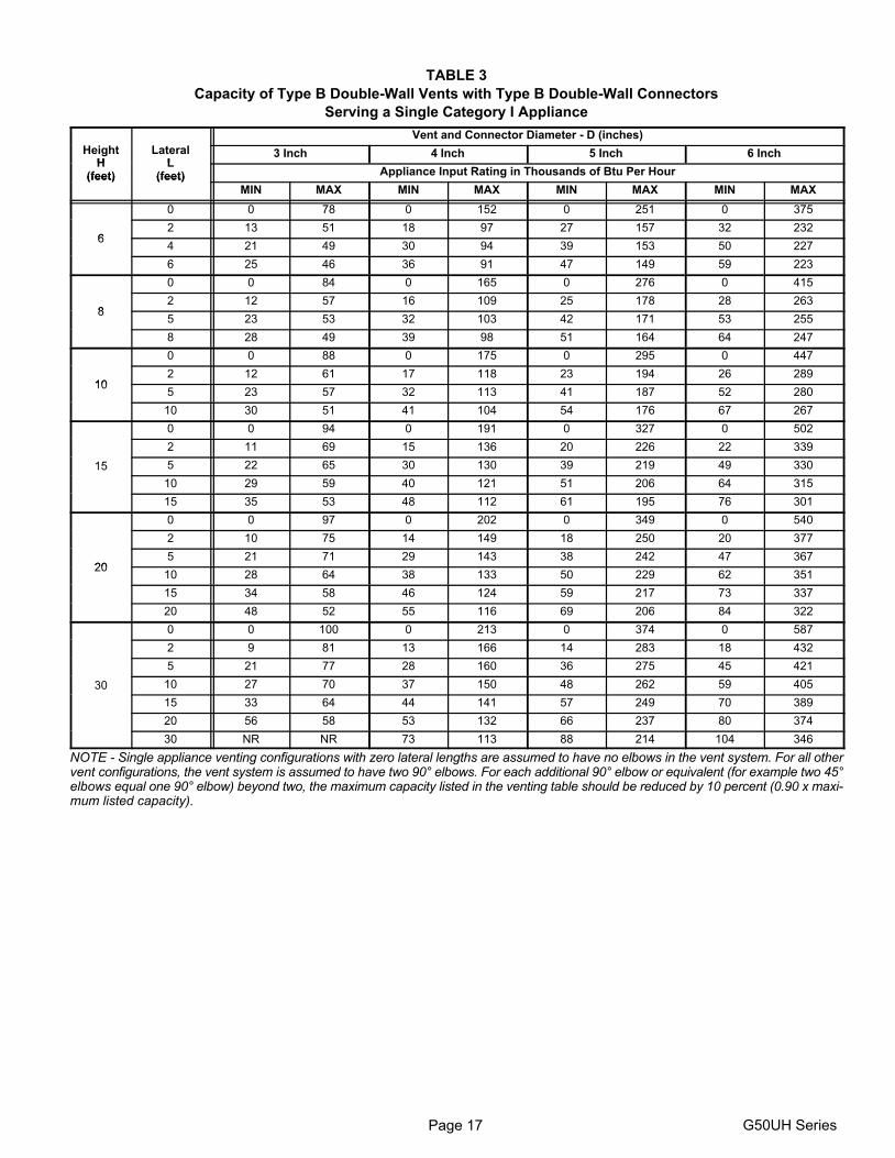
TABLE 3
Capacity of Type B Double−Wall Vents with Type B Double−Wall Connectors
Serving a Single Category I Appliance
Vent and Connector Diameter − D (inches)
HeightH
LateralL
3 Inch 4 Inch 5 Inch 6 InchH
(feet)L
(feet) Appliance Input Rating in Thousands of Btu Per Hour(feet) (feet)
MIN MAX MIN MAX MIN MAX MIN MAX
0 0 78 0 152 0 251 0 375
62 13 51 18 97 27 157 32 232
64 21 49 30 94 39 153 50 227
6 25 46 36 91 47 149 59 223
0 0 84 0 165 0 276 0 415
82 12 57 16 109 25 178 28 263
85 23 53 32 103 42 171 53 255
8 28 49 39 98 51 164 64 247
0 0 88 0 175 0 295 0 447
102 12 61 17 118 23 194 26 289
105 23 57 32 113 41 187 52 280
10 30 51 41 104 54 176 67 267
0 0 94 0 191 0 327 0 502
2 11 69 15 136 20 226 22 339
15 5 22 65 30 130 39 219 49 330
10 29 59 40 121 51 206 64 315
15 35 53 48 112 61 195 76 301
0 0 97 0 202 0 349 0 540
2 10 75 14 149 18 250 20 377
205 21 71 29 143 38 242 47 367
2010 28 64 38 133 50 229 62 351
15 34 58 46 124 59 217 73 337
20 48 52 55 116 69 206 84 322
0 0 100 0 213 0 374 0 587
2 9 81 13 166 14 283 18 432
5 21 77 28 160 36 275 45 421
30 10 27 70 37 150 48 262 59 405
15 33 64 44 141 57 249 70 389
20 56 58 53 132 66 237 80 374
30 NR NR 73 113 88 214 104 346
NOTE − Single appliance venting configurations with zero lateral lengths are assumed to have no elbows in the vent system. For all othervent configurations, the vent system is assumed to have two 90° elbows. For each additional 90° elbow or equivalent (for example two 45°elbows equal one 90° elbow) beyond two, the maximum capacity listed in the venting table should be reduced by 10 percent (0.90 x maxi-mum listed capacity).
Page 18505254M 05/2009
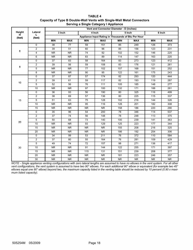
TABLE 4
Capacity of Type B Double−Wall Vents with Single−Wall Metal Connectors
Serving a Single Category I Appliance
Vent and Connector Diameter − D (inches)
HeightH
LateralL
3 Inch 4 Inch 5 Inch 6 InchH
(feet)L
(feet) Appliance Input Rating in Thousands of Btu Per Hour(feet) (feet)
MIN MAX MIN MAX MIN MAX MIN MAX
0 38 77 59 151 85 249 126 373
62 39 51 60 96 85 156 123 231
64 NR NR 74 92 102 152 146 225
6 NR NR 83 89 114 147 163 220
0 37 83 58 164 83 273 123 412
82 39 56 59 108 83 176 121 261
85 NR NR 77 102 107 168 151 252
8 NR NR 90 95 122 161 175 243
0 37 87 57 174 82 293 120 444
102 39 61 59 117 82 193 119 287
105 52 56 76 111 105 185 148 277
10 NR NR 97 100 132 171 188 261
0 36 93 56 190 80 325 116 499
2 38 69 57 136 80 225 115 337
15 5 51 63 75 128 102 216 144 326
10 NR NR 95 116 128 201 182 308
15 NR NR NR NR 158 186 220 290
0 35 96 54 200 78 346 114 537
2 37 74 56 148 78 248 113 375
205 50 68 73 140 100 239 141 363
2010 NR NR 93 129 125 223 177 344
15 NR NR NR NR 155 208 216 325
20 NR NR NR NR 186 192 254 306
0 34 99 53 211 76 372 110 584
2 37 80 55 164 76 281 109 429
5 49 74 72 157 98 271 136 417
30 10 NR NR 91 144 122 255 171 397
15 NR NR 115 131 151 239 208 377
20 NR NR NR NR 181 223 246 357
30 NR NR NR NR NR NR NR NR
NOTE − Single appliance venting configurations with zero lateral lengths are assumed to have no elbows in the vent system. For all othervent configurations, the vent system is assumed to have two 90° elbows. For each additional 90° elbow or equivalent (for example two 45°elbows equal one 90° elbow) beyond two, the maximum capacity listed in the venting table should be reduced by 10 percent (0.90 x maxi-mum listed capacity).
Page 19 G50UH Series
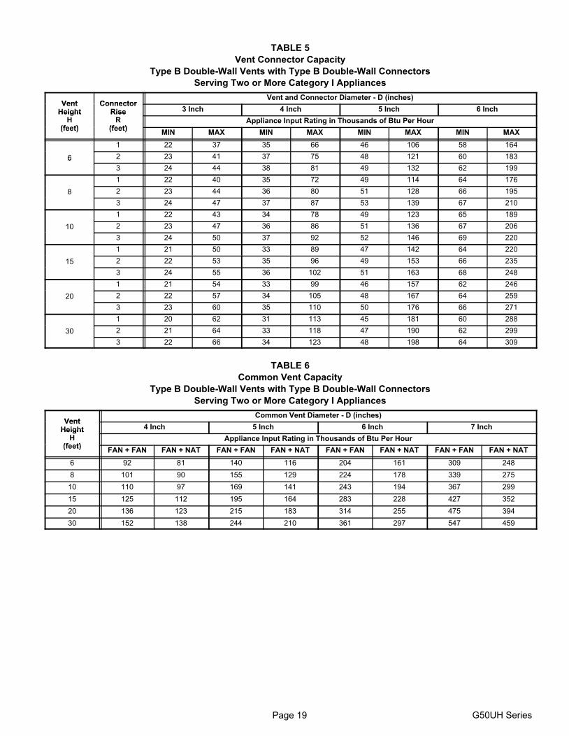
TABLE 5
Vent Connector Capacity
Type B Double−Wall Vents with Type B Double−Wall Connectors
Serving Two or More Category I Appliances
Vent ConnectorVent and Connector Diameter − D (inches)
VentHeight
ConnectorRise 3 Inch 4 Inch 5 Inch 6 InchHeight
H(feet)
RiseR
(feet)Appliance Input Rating in Thousands of Btu Per Hour
(feet) (feet)MIN MAX MIN MAX MIN MAX MIN MAX
1 22 37 35 66 46 106 58 164
6 2 23 41 37 75 48 121 60 1836
3 24 44 38 81 49 132 62 199
1 22 40 35 72 49 114 64 176
8 2 23 44 36 80 51 128 66 195
3 24 47 37 87 53 139 67 210
1 22 43 34 78 49 123 65 189
10 2 23 47 36 86 51 136 67 206
3 24 50 37 92 52 146 69 220
1 21 50 33 89 47 142 64 220
15 2 22 53 35 96 49 153 66 235
3 24 55 36 102 51 163 68 248
1 21 54 33 99 46 157 62 246
20 2 22 57 34 105 48 167 64 259
3 23 60 35 110 50 176 66 271
1 20 62 31 113 45 181 60 288
30 2 21 64 33 118 47 190 62 299
3 22 66 34 123 48 198 64 309
TABLE 6
Common Vent Capacity
Type B Double−Wall Vents with Type B Double−Wall Connectors
Serving Two or More Category I Appliances
VentCommon Vent Diameter − D (inches)
VentHeight 4 Inch 5 Inch 6 Inch 7 InchHeight
H(feet)
Appliance Input Rating in Thousands of Btu Per Hour(feet)
FAN + FAN FAN + NAT FAN + FAN FAN + NAT FAN + FAN FAN + NAT FAN + FAN FAN + NAT
6 92 81 140 116 204 161 309 248
8 101 90 155 129 224 178 339 275
10 110 97 169 141 243 194 367 299
15 125 112 195 164 283 228 427 352
20 136 123 215 183 314 255 475 394
30 152 138 244 210 361 297 547 459
Page 20505254M 05/2009
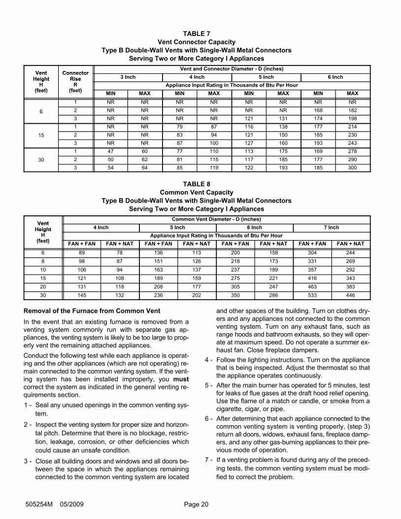
TABLE 7
Vent Connector Capacity
Type B Double−Wall Vents with Single−Wall Metal Connectors
Serving Two or More Category I Appliances
Vent ConnectorVent and Connector Diameter − D (inches)
VentHeight
ConnectorRise 3 Inch 4 Inch 5 Inch 6 InchHeight
H(feet)
RiseR
(feet)Appliance Input Rating in Thousands of Btu Per Hour
(feet) (feet)MIN MAX MIN MAX MIN MAX MIN MAX
1 NR NR NR NR NR NR NR NR
6 2 NR NR NR NR NR NR 168 1826
3 NR NR NR NR 121 131 174 198
1 NR NR 79 87 116 138 177 214
15 2 NR NR 83 94 121 150 185 230
3 NR NR 87 100 127 160 193 243
1 47 60 77 110 113 175 169 278
30 2 50 62 81 115 117 185 177 290
3 54 64 85 119 122 193 185 300
TABLE 8
Common Vent Capacity
Type B Double−Wall Vents with Single−Wall Metal Connectors
Serving Two or More Category I Appliances
VentCommon Vent Diameter − D (inches)
VentHeight 4 Inch 5 Inch 6 Inch 7 InchHeight
H(feet)
Appliance Input Rating in Thousands of Btu Per Hour(feet)
FAN + FAN FAN + NAT FAN + FAN FAN + NAT FAN + FAN FAN + NAT FAN + FAN FAN + NAT
6 89 78 136 113 200 158 304 244
8 98 87 151 126 218 173 331 269
10 106 94 163 137 237 189 357 292
15 121 108 189 159 275 221 416 343
20 131 118 208 177 305 247 463 383
30 145 132 236 202 350 286 533 446
Removal of the Furnace from Common Vent
In the event that an existing furnace is removed from a
venting system commonly run with separate gas ap-
pliances, the venting system is likely to be too large to prop-
erly vent the remaining attached appliances.
Conduct the following test while each appliance is operat-
ing and the other appliances (which are not operating) re-
main connected to the common venting system. If the vent-
ing system has been installed improperly, you must
correct the system as indicated in the general venting re-
quirements section.
1 − Seal any unused openings in the common venting sys-
tem.
2 − Inspect the venting system for proper size and horizon-
tal pitch. Determine that there is no blockage, restric-
tion, leakage, corrosion, or other deficiencies which
could cause an unsafe condition.
3 − Close all building doors and windows and all doors be-
tween the space in which the appliances remaining
connected to the common venting system are located
and other spaces of the building. Turn on clothes dry-
ers and any appliances not connected to the common
venting system. Turn on any exhaust fans, such as
range hoods and bathroom exhausts, so they will oper-
ate at maximum speed. Do not operate a summer ex-
haust fan. Close fireplace dampers.
4 − Follow the lighting instructions. Turn on the appliance
that is being inspected. Adjust the thermostat so that
the appliance operates continuously.
5 − After the main burner has operated for 5 minutes, test
for leaks of flue gases at the draft hood relief opening.
Use the flame of a match or candle, or smoke from a
cigarette, cigar, or pipe.
6 − After determining that each appliance connected to the
common venting system is venting properly, (step 3)
return all doors, widows, exhaust fans, fireplace damp-
ers, and any other gas−burning appliances to their pre-
vious mode of operation.
7 − If a venting problem is found during any of the preced-
ing tests, the common venting system must be modi-
fied to correct the problem.
Page 21 G50UH Series
Resize the common venting system to the minimum
vent pipe size determined by using the appropriate
tables in appendix G. (These are in the current stan-
dards of the National Fuel Gas Code ANSI Z223.1 in
the USA, and the appropriate Category 1 Natural Gas
and Propane appliances venting sizing tables in the
current standards of the CSA B149 Natural Gas and
Propane Installation Codes in Canada.)
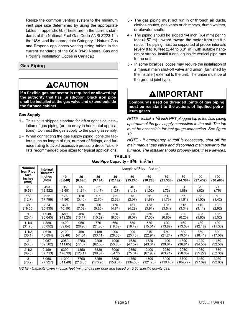
Gas Piping
CAUTIONIf a flexible gas connector is required or allowed bythe authority that has jurisdiction, black iron pipeshall be installed at the gas valve and extend outsidethe furnace cabinet.
Gas Supply
1 − This unit is shipped standard for left or right side instal-
lation of gas piping (or top entry in horizontal applica-
tions). Connect the gas supply to the piping assembly.
2 − When connecting the gas supply piping, consider fac-
tors such as length of run, number of fittings, and fur-
nace rating to avoid excessive pressure drop. Table 9
lists recommended pipe sizes for typical applications.
3 − The gas piping must not run in or through air ducts,
clothes chutes, gas vents or chimneys, dumb waiters,
or elevator shafts.
4 − The piping should be sloped 1/4 inch (6.4 mm) per 15
feet (4.57 m) upward toward the meter from the fur-
nace. The piping must be supported at proper intervals
[every 8 to 10 feet (2.44 to 3.01 m)] with suitable hang-
ers or straps. Install a drip leg inside vertical pipe runs
to the unit.
5 − In some localities, codes may require the installation of
a manual main shut-off valve and union (furnished by
the installer) external to the unit. The union must be of
the ground joint type.
IMPORTANTCompounds used on threaded joints of gas pipingmust be resistant to the actions of liquified petro-leum gases.
NOTE − Install a 1/8 inch NPT plugged tap in the field piping
upstream of the gas supply connection to the unit. The tap
must be accessible for test gauge connection. See figure
19.
NOTE − If emergency shutoff is necessary, shut off the
main manual gas valve and disconnect main power to the
furnace. The installer should properly label these devices.
TABLE 9
Gas Pipe Capacity − ft3/hr (m3/hr)
NominalIron Pipe
InternalDiameter
Length of Pipe − feet (m)Iron Pipe
Sizeinches(mm)
Diameterinches(mm)
10(3.048)
20(6.096)
30(9.144)
40(12.192)
50(15.240)
60(18.288)
70(21.336)
80(24.384)
90(27.432)
100(30.480)
3/8(9.53)
.493(12.522)
95(2.69)
65(1.84)
52(1.47)
45(1.27)
40(1.13)
36(1.02)
33(.73)
31(.88)
29(.82)
27(.76)
1/2(12.7)
.622(17.799)
175(4.96)
120(3.40)
97(2.75)
82(2.32)
73(2.07)
66(1.87)
61(1.73)
57(1.61)
53(1.50)
50(1.42)
3/4(19.05)
.824(20.930)
360(10.19)
250(7.08)
200(5.66)
170(4.81)
151(4.28)
138(3.91)
125(3.54)
118(3.34)
110(3.11)
103(2.92)
1(25.4)
1.049(26.645)
680(919.25)
465(13.17)
375(10.62)
320(9.06)
285(8.07)
260(7.36)
240(6.80)
220(6.23)
205(5.80)
195(5.52)
1−1/4(31.75)
1.380(35.052)
1400(39.64)
950(26.90)
770(21.80)
660(18.69)
580(16.42)
530(15.01)
490(13.87)
460(13.03)
430(12.18)
400(11.33)
1−1/2(38.1)
1.610(40.894)
2100(59.46)
460(41.34)
1180(33.41)
990(28.03)
900(25.48)
810(22.94)
750(21.24)
690(19.54)
650(18.41)
620(17.56)
2(50.8)
2.067(52.502)
3950(111.85)
2750(77.87)
2200(62.30)
1900(53.80)
1680(47.57)
1520(43.04)
1400(39.64)
1300(36.81)
1220(34.55)
1150(32.56)
2−1/2(63.5)
2.469(67.713)
6300(178.39)
4350(123.17)
3520(99.67)
3000(84.95
2650(75.04)
2400(67.96)
2250(63.71)
2050(58.05)
1950(55.22)
1850(52.38)
3(76.2)
3.068(77.927)
11000(311.48)
7700(218.03)
6250(176.98)
5300(150.07)
4750(134.50)
4300(121.76)
3900(110.43)
3700(104.77)
3450(97.69)
3250(92.03)
NOTE − Capacity given in cubic feet (m3 ) of gas per hour and based on 0.60 specific gravity gas.
Page 22505254M 05/2009
GROUNDJOINTUNION
AUTOMATICGAS VALVE(with manual
shut−off valve)
FIELDPROVIDED
AND INSTALLED
GROUNDJOINTUNION
Left Side Piping(Standard)
Right Side Piping(Alternate)
AUTOMATICGAS VALVE(with manual
shut−off valve)
DRIP LEG
DRIP LEG
MANUALMAIN SHUT−OFF
VALVE(With 1/8 in. NPT
Plugged Tap Shown)
MANUALMAIN SHUT−OFF
VALVE(With 1/8 in. NPT
Plugged TapShown)
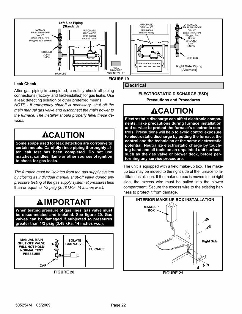
FIGURE 19
Leak Check
After gas piping is completed, carefully check all piping
connections (factory− and field−installed) for gas leaks. Use
a leak detecting solution or other preferred means.
NOTE − If emergency shutoff is necessary, shut off the
main manual gas valve and disconnect the main power to
the furnace. The installer should properly label these de-
vices.
CAUTIONSome soaps used for leak detection are corrosive tocertain metals. Carefully rinse piping thoroughly af-ter leak test has been completed. Do not usematches, candles, flame or other sources of ignitionto check for gas leaks.
The furnace must be isolated from the gas supply system
by closing its individual manual shut-off valve during any
pressure testing of the gas supply system at pressures less
than or equal to 1/2 psig (3.48 kPa, 14 inches w.c.).
IMPORTANTWhen testing pressure of gas lines, gas valve mustbe disconnected and isolated. See figure 20. Gasvalves can be damaged if subjected to pressuresgreater than 1/2 psig (3.48 kPa, 14 inches w.c.).
MANUAL MAINSHUT−OFF VALVEWILL NOT HOLDNORMAL TEST
PRESSURE
CAP
ISOLATEGAS VALVE
FURNACE
FIGURE 20
Electrical
ELECTROSTATIC DISCHARGE (ESD)
Precautions and Procedures
CAUTIONElectrostatic discharge can affect electronic compo-nents. Take precautions during furnace installationand service to protect the furnace’s electronic con-trols. Precautions will help to avoid control exposureto electrostatic discharge by putting the furnace, thecontrol and the technician at the same electrostaticpotential. Neutralize electrostatic charge by touch-ing hand and all tools on an unpainted unit surface,such as the gas valve or blower deck, before per-forming any service procedure.
The unit is equipped with a field make−up box. The make−
up box may be moved to the right side of the furnace to fa-
cilitate installation. If the make−up box is moved to the right
side, the excess wire must be pulled into the blower
compartment. Secure the excess wire to the existing har-
ness to protect it from damage.
INTERIOR MAKE−UP BOX INSTALLATION
MAKE−UPBOX
Right Side
FIGURE 21
Page 23 G50UH Series
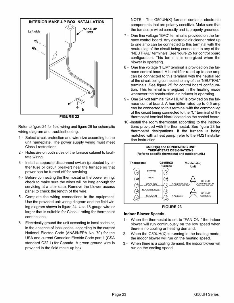
INTERIOR MAKE−UP BOX INSTALLATION
MAKE−UPBOXLeft side
FIGURE 22
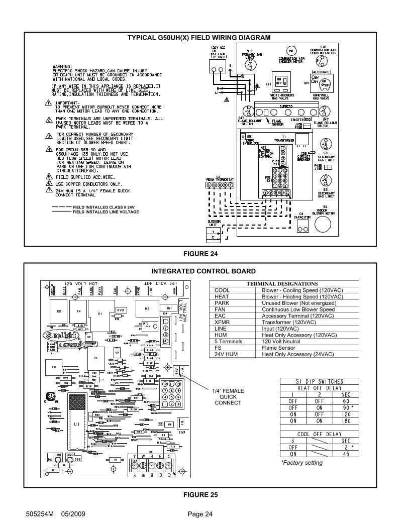
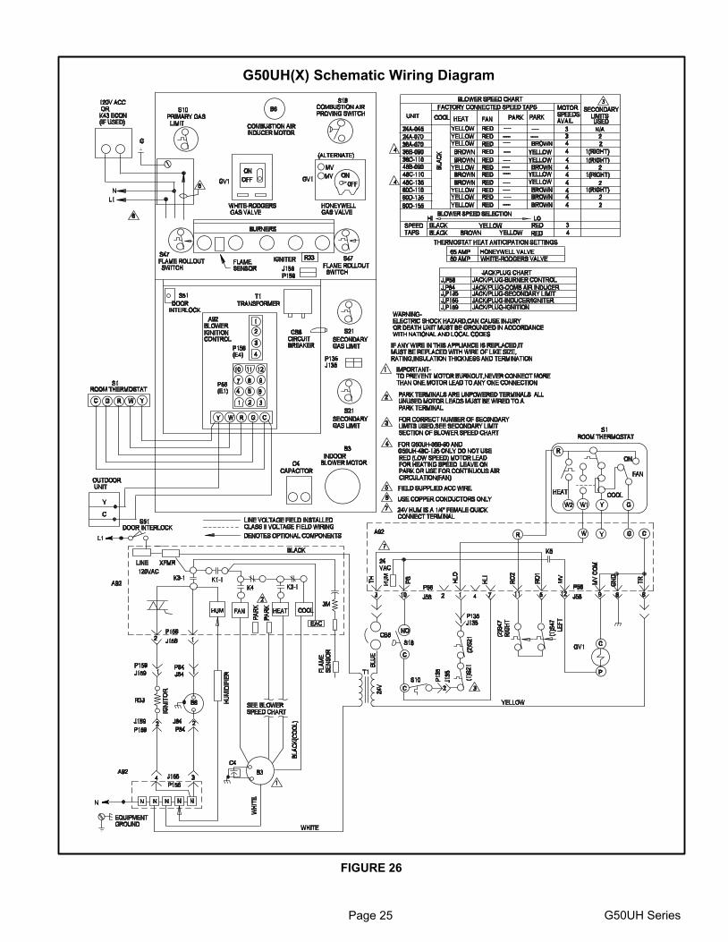
Refer to figure 24 for field wiring and figure 26 for schematic
wiring diagram and troubleshooting.
1 − Select circuit protection and wire size according to the
unit nameplate. The power supply wiring must meet
Class I restrictions.
2 − Holes are on both sides of the furnace cabinet to facili-
tate wiring.
3 − Install a separate disconnect switch (protected by ei-
ther fuse or circuit breaker) near the furnace so that
power can be turned off for servicing.
4 − Before connecting the thermostat or the power wiring,
check to make sure the wires will be long enough for
servicing at a later date. Remove the blower access
panel to check the length of the wire.
5 − Complete the wiring connections to the equipment.
Use the provided unit wiring diagram and the field wir-
ing diagram shown in figure 24. Use 18−gauge wire or
larger that is suitable for Class II rating for thermostat
connections.
6 − Electrically ground the unit according to local codes or,
in the absence of local codes, according to the current
National Electric Code (ANSI/NFPA No. 70) for the
USA and current Canadian Electric Code part 1 (CSA
standard C22.1) for Canada. A green ground wire is
provided in the field make−up box.
NOTE − The G50UH(X) furnace contains electronic
components that are polarity sensitive. Make sure that
the furnace is wired correctly and is properly grounded.
7 − One line voltage �EAC" terminal is provided on the fur-nace control board. Any electronic air cleaner rated upto one amp can be connected to this terminal with theneutral leg of the circuit being connected to any of the�NEUTRAL" terminals. See figure 25 for control boardconfiguration. This terminal is energized when theblower is operating.
8 − One line voltage �HUM" terminal is provided on the fur-nace control board. A humidifier rated up to one ampcan be connected to this terminal with the neutral legof the circuit being connected to any of the �NEUTRAL"terminals. See figure 25 for control board configura-tion. This terminal is energized in the heating modewhenever the combustion air inducer is operating.
9 − One 24 volt terminal �24V HUM" is provided on the fur-nace control board. A humidifier rated up to 0.5 ampcan be connected to this terminal with the common legof the circuit being connected to the �C" terminal of thethermostat terminal block located on the control board.
10 −Install the room thermostat according to the instruc-tions provided with the thermostat. See figure 23 forthermostat designations. If the furnace is beingmatched with a heat pump, refer to the FM21 installa-tion instruction.
Thermostat
COMPRESSOR�
COMMON
HS UNITCOMMON
HS UNITCOMPRESSOR
G50UH(X)Furnace
CondensingUnit
G50UH(X) and CONDENSING UNITTHERMOSTAT DESIGNATIONS
(Refer to specific thermostat and outdoor unit.)
COMMON
POWER
HEAT
INDOOR BLOWER
Y
C
R
G
W1
Y
C
R
G
W
COOLING
FIGURE 23
Indoor Blower Speeds
1 − When the thermostat is set to �FAN ON," the indoorblower will run continuously on the low speed whenthere is no cooling or heating demand.
2 − When the G50UH(X) is running in the heating mode,the indoor blower will run on the heating speed.
3 − When there is a cooling demand, the indoor blower willrun on the cooling speed.
Page 24505254M 05/2009
FIELD INSTALLED CLASS II 24VFIELD INSTALLED LINE VOLTAGE
TYPICAL G50UH(X) FIELD WIRING DIAGRAM
FIGURE 24
INTEGRATED CONTROL BOARD
COOL
HEAT
PARK
FAN
EAC
XFMR
LINE
HUM
5 Terminals
FS
24V HUM
Blower − Cooling Speed (120VAC)
Blower − Heating Speed (120VAC)
Unused Blower (Not energized)
Continuous Low Blower Speed
Accessory Terminal (120VAC)
Transformer (120VAC)
Input (120VAC)
Heat Only Accessory (120VAC)
120 Volt Neutral
Flame Sensor
Heat Only Accessory (24VAC)
TERMINAL DESIGNATIONS
1/4" FEMALEQUICK
CONNECT*
*
*Factory setting
FIGURE 25
Page 25 G50UH Series
G50UH(X) Schematic Wiring Diagram
FIGURE 26

Page 26505254M 05/2009
Unit Start−Up
FOR YOUR SAFETY READ BEFORE LIGHTING
WARNINGDo not use this furnace if any part has been underwa-ter. Immediately call a licensed professional servicetechnician to inspect the furnace and to replace anypart of the control system and any gas control whichhas been under water.
WARNINGIf overheating occurs or if gas supply fails to shut off,shut off the manual gas valve to the appliance beforeshutting off electrical supply.
CAUTIONBefore attempting to perform any service or mainte-nance, turn the electrical power to unit OFF at dis-connect switch.
BEFORE LIGHTING smell all around the appliance area
for gas. Be sure to smell next to the floor because some gas
is heavier than air and will settle on the floor.
The gas valve on the G50UH(X) unit may be equipped with
either a gas control knob or gas control lever. Use only your
hand to push the lever or to turn the gas control knob. Never
use tools. If the knob will not turn or if the lever will not move
by hand, do not try to repair it. Call a licensed professional
service technician (or equivalent). Force or attempted re-
pair may result in a fire or explosion.
Placing the furnace into operation:
G50UH(X) units are equipped with a SureLight® ignition
system. Do not attempt to manually light burners on these
furnaces. Each time the thermostat calls for heat, the burn-
ers will automatically light. The ignitor does not get hot
when there is no call for heat on units with SureLight® igni-
tion system.
WARNINGIf you do not follow these instructions exactly, a fireor explosion may result causing property damage,personal injury or death.
Gas Valve Operation (Figures 27, 28 and 29)
1 − STOP! Read the safety information at the beginning of
this section.
2 − Set the thermostat to the lowest setting.
3 − Turn off all electrical power to the unit.
4 − This furnace is equipped with an ignition device which
automatically lights the burners. Do not try to light the
burners by hand.
5 − Remove the upper access panel.
6 − Honeywell VR8205 Gas Valve with ON/OFF Switch −
Move gas valve switch to OFF. See figure 27.
Honeywell VR8205 Gas Valve with Control Knob −
Turn knob on gas valve clockwise to OFF. Do not
force. See figure 28.
White Rodgers 36G Gas Valve − Move gas valve
switch to OFF. See figure 29.
7 − Wait five minutes to clear out any gas. If you then smell
gas, STOP! Immediately call your gas supplier from a
neighbor’s phone. Follow the gas supplier’s instruc-
tions. If you do not smell gas go to next step.
Honeywell VR8205 Series Gas Valve(With On/Off Switch)
GAS VALVE ON/OFF SWITCH SHOWN IN OFF POSITION
MANIFOLDPRESSURE
OUTLET
MANIFOLDPRESSURE
ADJUSTMENTSCREW
(under cap)
FIGURE 27
ON
OFF
Honeywell VR8205 Series Gas Valvewith Gas Control Knob
GAS VALVE SHOWN IN OFF POSITION
MANIFOLDPRESSURE
ADJUSTMENTSCREW
MANIFOLDPRESSURE
OUTLET
FIGURE 28
White Rodgers 36G Series Gas Valve
GAS VALVE SHOWN IN OFF POSITION
MANIFOLDPRESSURE
ADJUSTMENTSCREW
(Under coverscrew)
OUTLETPRESSURE
POST
INLETPRESSURE
POST
FIGURE 29
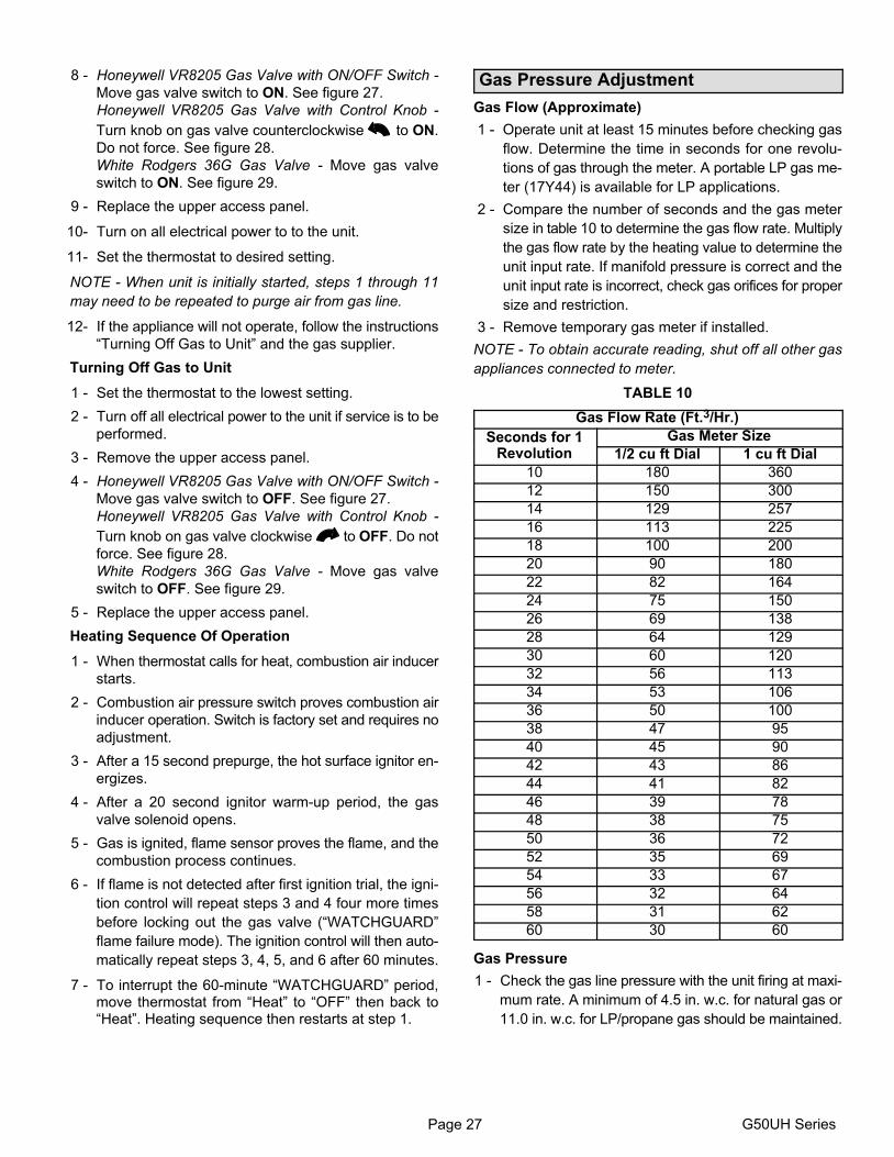
Page 27 G50UH Series
8 − Honeywell VR8205 Gas Valve with ON/OFF Switch −
Move gas valve switch to ON. See figure 27.
Honeywell VR8205 Gas Valve with Control Knob −
Turn knob on gas valve counterclockwise to ON.
Do not force. See figure 28.
White Rodgers 36G Gas Valve − Move gas valve
switch to ON. See figure 29.
9 − Replace the upper access panel.
10− Turn on all electrical power to to the unit.
11− Set the thermostat to desired setting.
NOTE − When unit is initially started, steps 1 through 11
may need to be repeated to purge air from gas line.
12− If the appliance will not operate, follow the instructions
�Turning Off Gas to Unit" and the gas supplier.
Turning Off Gas to Unit
1 − Set the thermostat to the lowest setting.
2 − Turn off all electrical power to the unit if service is to be
performed.
3 − Remove the upper access panel.
4 − Honeywell VR8205 Gas Valve with ON/OFF Switch −
Move gas valve switch to OFF. See figure 27.
Honeywell VR8205 Gas Valve with Control Knob −
Turn knob on gas valve clockwise to OFF. Do not
force. See figure 28.
White Rodgers 36G Gas Valve − Move gas valve
switch to OFF. See figure 29.
5 − Replace the upper access panel.
Heating Sequence Of Operation
1 − When thermostat calls for heat, combustion air inducer
starts.
2 − Combustion air pressure switch proves combustion air
inducer operation. Switch is factory set and requires no
adjustment.
3 − After a 15 second prepurge, the hot surface ignitor en-
ergizes.
4 − After a 20 second ignitor warm−up period, the gas
valve solenoid opens.
5 − Gas is ignited, flame sensor proves the flame, and the
combustion process continues.
6 − If flame is not detected after first ignition trial, the igni-
tion control will repeat steps 3 and 4 four more times
before locking out the gas valve (�WATCHGUARD"
flame failure mode). The ignition control will then auto-
matically repeat steps 3, 4, 5, and 6 after 60 minutes.
7 − To interrupt the 60−minute �WATCHGUARD" period,move thermostat from �Heat" to �OFF" then back to�Heat". Heating sequence then restarts at step 1.
Gas Pressure Adjustment
Gas Flow (Approximate)
1 − Operate unit at least 15 minutes before checking gas
flow. Determine the time in seconds for one revolu-
tions of gas through the meter. A portable LP gas me-
ter (17Y44) is available for LP applications.
2 − Compare the number of seconds and the gas meter
size in table 10 to determine the gas flow rate. Multiply
the gas flow rate by the heating value to determine the
unit input rate. If manifold pressure is correct and the
unit input rate is incorrect, check gas orifices for proper
size and restriction.
3 − Remove temporary gas meter if installed.
NOTE − To obtain accurate reading, shut off all other gas
appliances connected to meter.
TABLE 10
Gas Flow Rate (Ft.3/Hr.)
Seconds for 1 Gas Meter SizeSeconds for 1Revolution 1/2 cu ft Dial 1 cu ft Dial
10 180 360
12 150 300
14 129 257
16 113 225
18 100 200
20 90 180
22 82 164
24 75 150
26 69 138
28 64 129
30 60 120
32 56 113
34 53 106
36 50 100
38 47 95
40 45 90
42 43 86
44 41 82
46 39 78
48 38 75
50 36 72
52 35 69
54 33 67
56 32 64
58 31 62
60 30 60
Gas Pressure
1 − Check the gas line pressure with the unit firing at maxi-
mum rate. A minimum of 4.5 in. w.c. for natural gas or
11.0 in. w.c. for LP/propane gas should be maintained.
Page 28505254M 05/2009
2 − After the line pressure has been checked and ad-
justed, check the manifold pressure. A natural gas to
LP/propane gas changeover kit is required to convert
the unit. Manifold pressure for all units fueled by natu-
ral gas at all altitudes is 3.5" w.c. Manifold pressure for
all units fueled by L.P./propane gas at all altitudes is
10.0" w.c. See figures 27, 28 and 29 for the location of
the manifold pressure adjustment screws.
High Altitude Information
NOTE − In Canada, certification for installations at eleva-
tions over 4500 feet (1372 m) is the jurisdiction of local au-
thorities.
Manifold pressure for all units fueled by natural gas at all
altitudes is 3.5" w.c. Manifold pressure for all units fueled by
L.P./propane gas at all altitudes is 10.0" w.c.
NOTE − A natural to L.P. propane gas changeover kit is
necessary to convert this unit. L.P. conversion kit 25W20 is
used with all units installed at altitudes up to 7,500 feet. L.P.
conversion kit 25W21 is used with all units installed at alti-
tudes from 7,501 to 10,000 feet above sea level. Refer to
the changeover kit installation instruction for the conver-
sion procedure.
NOTE − Units fueled by natural gas and installed at alti-
tudes of 7501−10,000 feet above sea level require installa-
tion of a high altitude orifice kit (59M17).
The combustion air pressure switches are factory−set and
require no adjustment. The existing unit pressure switch
must be replaced by pressure switch 56L32 for G50UH(X)
units installed at altitudes from 7,501 to 10,000 feet above
sea level.
Other Unit Adjustments
Primary and Secondary Limits
The primary limit is located on the heating compartment
vestibule panel. The secondary limits (if equipped) are lo-
cated in the blower compartment, attached to the back side
of the blower. These limits are factory set and require no
adjustment.
Flame Rollout Switches (Two)
These manually reset switches are located on (or inside of)
the burner box. If tripped, check for adequate combustion
air before resetting.
Pressure Switch
The pressure switch is located in the heating compartment
adjacent to the combustion air inducer. This switch checks
for proper combustion air inducer operation before allow-
ing ignition trial. The switch is factory−set and requires no
adjustment.
Temperature Rise
Place the unit into operation with a heating demand. After
supply and return air temperatures have stabilized, check
the temperature rise. If necessary, adjust the blower speed
to maintain the temperature rise within the range shown on
the unit nameplate. Increase the blower speed to decrease
the temperature. Decrease the blower speed to increase
the temperature rise. Failure to do adjust the temperature
rise may cause erratic limit operation.
Fan Control
Heating Mode −− The fan on delay of 45 seconds is not ad-justable. The fan off delay (amount of time that the bloweroperates after the heat demand has been satisfied) may beadjusted by setting S1 switches 1 and 2 located on the inte-grated control. The unit is shipped with a factory fan off set-ting of 90 seconds. The fan off delay affects comfort and isadjustable to satisfy individual applications. Adjust the fanoff delay to achieve a supply air temperature between 90°and 110°F at the exact moment that the blower is de−ener-gized. Longer off delay settings provide lower return airtemperatures; shorter settings provide higher return airtemperatures. See figure 25.Cooling Mode −− The cooling mode fan off delay (amount
of time that the blower operates after the cooling demand
has been satisfied) may be adjusted by setting S1 switch 3
located on the SureLight® control. In the off position, the
cooling fan off delay is 2 seconds. In the on position, the
cooling fan off delay is 45 seconds. See figure 25.
Thermostat Heat Anticipation
Set the heat anticipator setting (if adjustable) according to
the amp draw listed on the wiring diagram that is attached
to the unit.
Electrical
1 − Check all wiring for loose connections.
2 − Check for the correct voltage at the furnace (furnaceoperating).
3 − Check amp-draw on the blower motor.Motor Nameplate__________Actual__________
NOTE − Do not secure the electrical conduit directly to theair ducts or structure.
Blower Speeds
NOTE − CFM readings are taken external to unit with a dryevaporator coil and without accessories.
1 − Turn off electrical power to furnace.
2 − Remove blower access panel.
3 − Disconnect existing speed tap at control board speedterminal.
NOTE − Termination of any unused motor leads must be in-sulated.
4 − Refer to blower speed selection chart on unit wiringdiagram for desired heating or cooling speed.
5 − Connect selected speed tap at control board speedterminal.
6 − Resecure blower access panel.
7 − Turn on electrical power to furnace.
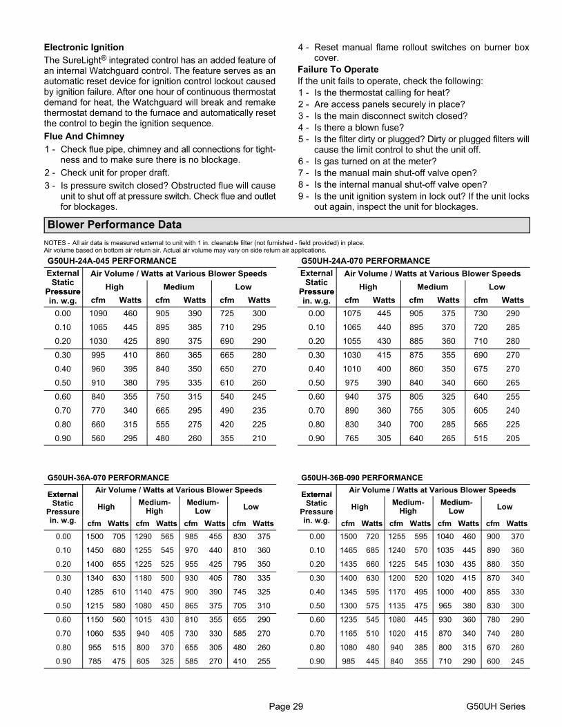
Page 29 G50UH Series
Electronic Ignition
The SureLight® integrated control has an added feature ofan internal Watchguard control. The feature serves as anautomatic reset device for ignition control lockout causedby ignition failure. After one hour of continuous thermostatdemand for heat, the Watchguard will break and remakethermostat demand to the furnace and automatically resetthe control to begin the ignition sequence.
Flue And Chimney
1 − Check flue pipe, chimney and all connections for tight-ness and to make sure there is no blockage.
2 − Check unit for proper draft.
3 − Is pressure switch closed? Obstructed flue will causeunit to shut off at pressure switch. Check flue and outletfor blockages.
4 − Reset manual flame rollout switches on burner boxcover.
Failure To Operate
If the unit fails to operate, check the following:
1 − Is the thermostat calling for heat?
2 − Are access panels securely in place?
3 − Is the main disconnect switch closed?
4 − Is there a blown fuse?
5 − Is the filter dirty or plugged? Dirty or plugged filters willcause the limit control to shut the unit off.
6 − Is gas turned on at the meter?
7 − Is the manual main shut-off valve open?
8 − Is the internal manual shut-off valve open?
9 − Is the unit ignition system in lock out? If the unit locksout again, inspect the unit for blockages.
Blower Performance Data
NOTES − All air data is measured external to unit with 1 in. cleanable filter (not furnished − field provided) in place. Air volume based on bottom air return air. Actual air volume may vary on side return air applications.
G50UH−24A−045 PERFORMANCE
ExternalSt ti
Air Volume / Watts at Various Blower SpeedsStatic
PressureHigh Medium Low
Pressurein. w.g. cfm Watts cfm Watts cfm Watts
0.00 1090 460 905 390 725 300
0.10 1065 445 895 385 710 295
0.20 1030 425 890 375 690 290
0.30 995 410 860 365 665 280
0.40 960 395 840 350 650 270
0.50 910 380 795 335 610 260
0.60 840 355 750 315 540 245
0.70 770 340 665 295 490 235
0.80 660 315 555 275 420 225
0.90 560 295 480 260 355 210
G50UH−24A−070 PERFORMANCE
ExternalSt ti
Air Volume / Watts at Various Blower SpeedsStatic
PressureHigh Medium Low
Pressurein. w.g. cfm Watts cfm Watts cfm Watts
0.00 1075 445 905 375 730 290
0.10 1065 440 895 370 720 285
0.20 1055 430 885 360 710 280
0.30 1030 415 875 355 690 270
0.40 1010 400 860 350 675 270
0.50 975 390 840 340 660 265
0.60 940 375 805 325 640 255
0.70 890 360 755 305 605 240
0.80 830 340 700 285 565 225
0.90 765 305 640 265 515 205
G50UH−36A−070 PERFORMANCE
ExternalAir Volume / Watts at Various Blower Speeds
ExternalStatic
Pressurei
HighMedium−
HighMedium−
LowLow
in. w.g. cfm Watts cfm Watts cfm Watts cfm Watts
0.00 1500 705 1290 565 985 455 830 375
0.10 1450 680 1255 545 970 440 810 360
0.20 1400 655 1225 525 955 425 795 350
0.30 1340 630 1180 500 930 405 780 335
0.40 1285 610 1140 475 900 390 745 325
0.50 1215 580 1080 450 865 375 705 310
0.60 1150 560 1015 430 810 355 655 290
0.70 1060 535 940 405 730 330 585 270
0.80 955 515 800 370 655 305 480 260
0.90 785 475 605 325 585 270 410 255
G50UH−36B−090 PERFORMANCE
ExternalAir Volume / Watts at Various Blower Speeds
ExternalStatic
Pressurei
HighMedium−
HighMedium−
LowLow
in. w.g. cfm Watts cfm Watts cfm Watts cfm Watts
0.00 1500 720 1255 595 1040 460 900 370
0.10 1465 685 1240 570 1035 445 890 360
0.20 1435 660 1225 545 1030 435 880 350
0.30 1400 630 1200 520 1020 415 870 340
0.40 1345 595 1170 495 1000 400 855 330
0.50 1300 575 1135 475 965 380 830 300
0.60 1235 545 1080 445 930 360 780 290
0.70 1165 510 1020 415 870 340 740 280
0.80 1080 480 940 385 800 315 670 260
0.90 985 445 840 355 710 290 600 245
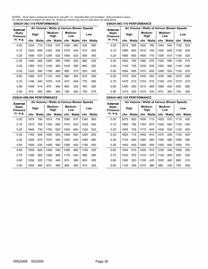
Page 30505254M 05/2009
NOTES − All air data is measured external to unit with 1 in. cleanable filter (not furnished − field provided) in place. Air volume based on bottom air return air. Actual air volume may vary on side return air applications.
G50UH−36C−110 PERFORMANCE
ExternalAir Volume / Watts at Various Blower Speeds
ExternalStatic
Pressurei
HighMedium−
HighMedium−
LowLow
in. w.g. cfm Watts cfm Watts cfm Watts cfm Watts
0.00 1555 715 1335 575 1085 460 925 365
0.10 1525 690 1320 545 1075 440 915 355
0.20 1490 670 1295 525 1065 420 900 340
0.30 1440 645 1260 495 1050 405 880 330
0.40 1385 615 1230 485 1030 390 865 320
0.50 1320 590 1190 460 995 375 835 300
0.60 1260 570 1135 430 960 355 815 295
0.70 1190 545 1075 410 915 345 775 285
0.80 1090 515 970 385 860 325 760 280
0.90 975 485 880 360 790 305 705 275
G50UH−48B−090 PERFORMANCE
ExternalAir Volume / Watts at Various Blower Speeds
ExternalStatic
Pressurei
HighMedium−
HighMedium−
LowLow
in. w.g. cfm Watts cfm Watts cfm Watts cfm Watts
0.00 1970 790 1810 735 1585 670 1340 565
0.10 1915 765 1760 695 1570 630 1325 540
0.20 1840 730 1700 620 1545 600 1320 520
0.30 1765 695 1640 625 1490 565 1295 500
0.40 1695 670 1570 595 1440 540 1260 480
0.50 1600 635 1490 560 1360 505 1195 450
0.60 1505 600 1400 530 1285 480 1140 425
0.70 1395 565 1265 485 1170 440 990 380
0.80 1250 520 1100 445 975 390 905 355
0.90 1005 460 870 385 900 365 810 325
G50UH−48C−110 PERFORMANCE
ExternalAir Volume / Watts at Various Blower Speeds
ExternalStatic
Pressurei
HighMedium−
HighMedium−
LowLow
in. w.g. cfm Watts cfm Watts cfm Watts cfm Watts
0.00 2015 895 1620 780 1340 640 1150 525
0.10 1965 850 1610 745 1340 640 1150 525
0.20 1895 805 1600 710 1335 615 1150 525
0.30 1820 765 1580 675 1330 590 1145 515
0.40 1740 725 1530 635 1320 560 1140 490
0.50 1665 695 1475 600 1285 525 1120 470
0.60 1575 650 1405 555 1230 490 1075 445
0.70 1475 610 1310 515 1165 470 1015 415
0.80 1350 560 1210 485 1080 430 930 380
0.90 1210 520 1070 430 870 365 740 325
G50UH−48C−135 PERFORMANCE
ExternalAir Volume / Watts at Various Blower Speeds
ExternalStatic
Pressurei
HighMedium−
HighMedium−
LowLow
in. w.g. cfm Watts cfm Watts cfm Watts cfm Watts
0.00 2075 820 1800 710 1425 570 1115 435
0.10 1990 790 1765 675 1420 545 1125 430
0.20 1905 745 1715 645 1405 525 1120 420
0.30 1825 715 1650 610 1375 505 1105 405
0.40 1740 680 1585 580 1355 485 1090 390
0.50 1640 645 1495 545 1300 455 1050 370
0.60 1540 615 1420 515 1225 430 1000 355
0.70 1420 575 1310 475 1140 400 935 330
0.80 1260 520 1155 425 1025 365 865 315
0.90 1125 495 1010 385 880 330 750 285
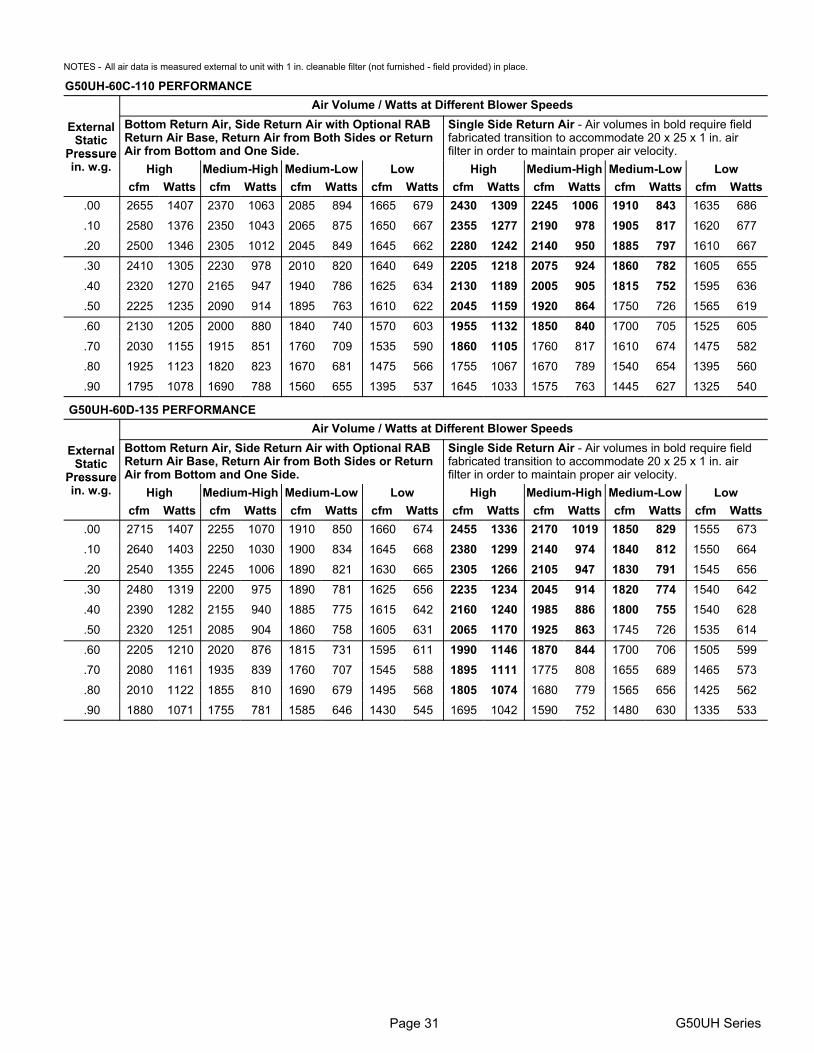
Page 31 G50UH Series
NOTES − All air data is measured external to unit with 1 in. cleanable filter (not furnished − field provided) in place.
G50UH−60C−110 PERFORMANCE
Air Volume / Watts at Different Blower Speeds
ExternalStatic
Pressure
Bottom Return Air, Side Return Air with Optional RABReturn Air Base, Return Air from Both Sides or ReturnAir from Bottom and One Side.
Single Side Return Air − Air volumes in bold require fieldfabricated transition to accommodate 20 x 25 x 1 in. airfilter in order to maintain proper air velocity.Pressure
in. w.g. High Medium−High Medium−Low Low High Medium−High Medium−Low Low
cfm Watts cfm Watts cfm Watts cfm Watts cfm Watts cfm Watts cfm Watts cfm Watts
.00 2655 1407 2370 1063 2085 894 1665 679 2430 1309 2245 1006 1910 843 1635 686
.10 2580 1376 2350 1043 2065 875 1650 667 2355 1277 2190 978 1905 817 1620 677
.20 2500 1346 2305 1012 2045 849 1645 662 2280 1242 2140 950 1885 797 1610 667
.30 2410 1305 2230 978 2010 820 1640 649 2205 1218 2075 924 1860 782 1605 655
.40 2320 1270 2165 947 1940 786 1625 634 2130 1189 2005 905 1815 752 1595 636
.50 2225 1235 2090 914 1895 763 1610 622 2045 1159 1920 864 1750 726 1565 619
.60 2130 1205 2000 880 1840 740 1570 603 1955 1132 1850 840 1700 705 1525 605
.70 2030 1155 1915 851 1760 709 1535 590 1860 1105 1760 817 1610 674 1475 582
.80 1925 1123 1820 823 1670 681 1475 566 1755 1067 1670 789 1540 654 1395 560
.90 1795 1078 1690 788 1560 655 1395 537 1645 1033 1575 763 1445 627 1325 540
G50UH−60D−135 PERFORMANCE
Air Volume / Watts at Different Blower Speeds
ExternalStatic
Pressure
Bottom Return Air, Side Return Air with Optional RABReturn Air Base, Return Air from Both Sides or ReturnAir from Bottom and One Side.
Single Side Return Air − Air volumes in bold require fieldfabricated transition to accommodate 20 x 25 x 1 in. airfilter in order to maintain proper air velocity.Pressure
in. w.g. High Medium−High Medium−Low Low High Medium−High Medium−Low Low
cfm Watts cfm Watts cfm Watts cfm Watts cfm Watts cfm Watts cfm Watts cfm Watts
.00 2715 1407 2255 1070 1910 850 1660 674 2455 1336 2170 1019 1850 829 1555 673
.10 2640 1403 2250 1030 1900 834 1645 668 2380 1299 2140 974 1840 812 1550 664
.20 2540 1355 2245 1006 1890 821 1630 665 2305 1266 2105 947 1830 791 1545 656
.30 2480 1319 2200 975 1890 781 1625 656 2235 1234 2045 914 1820 774 1540 642
.40 2390 1282 2155 940 1885 775 1615 642 2160 1240 1985 886 1800 755 1540 628
.50 2320 1251 2085 904 1860 758 1605 631 2065 1170 1925 863 1745 726 1535 614
.60 2205 1210 2020 876 1815 731 1595 611 1990 1146 1870 844 1700 706 1505 599
.70 2080 1161 1935 839 1760 707 1545 588 1895 1111 1775 808 1655 689 1465 573
.80 2010 1122 1855 810 1690 679 1495 568 1805 1074 1680 779 1565 656 1425 562
.90 1880 1071 1755 781 1585 646 1430 545 1695 1042 1590 752 1480 630 1335 533
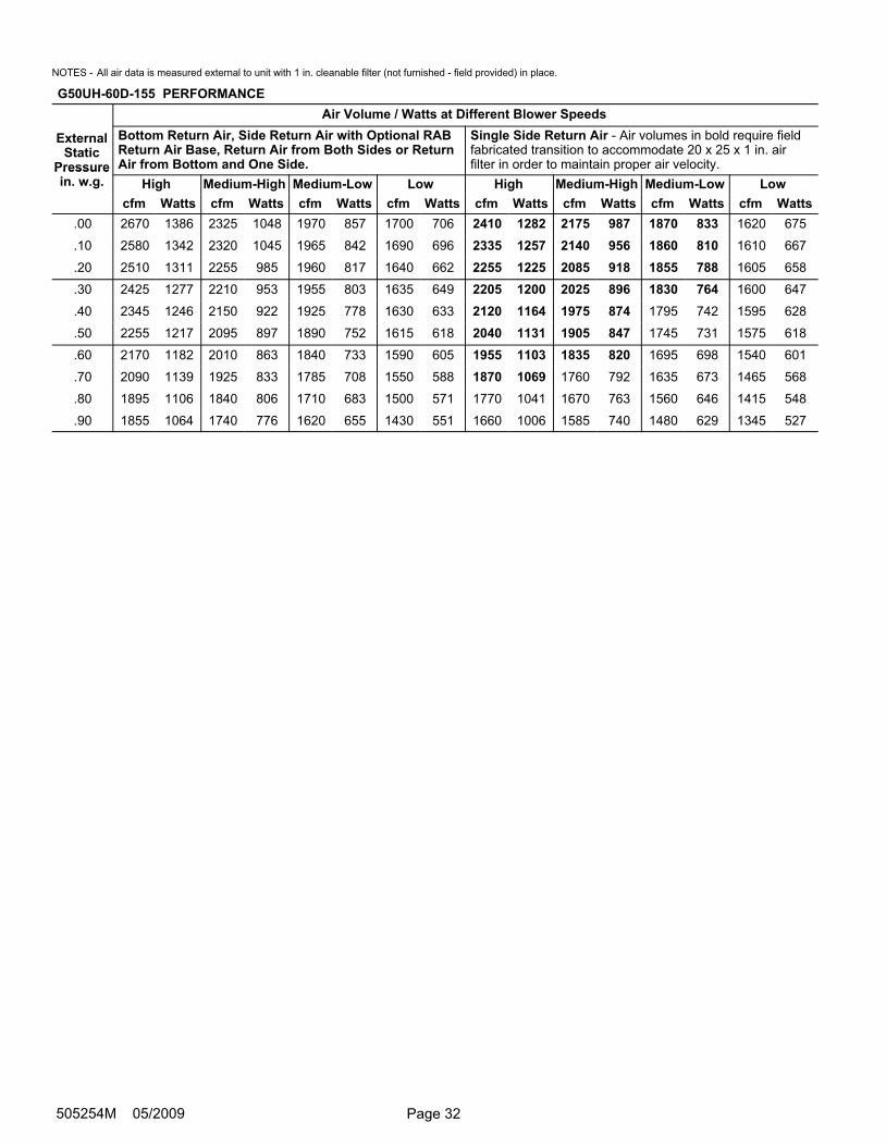
Page 32505254M 05/2009
NOTES − All air data is measured external to unit with 1 in. cleanable filter (not furnished − field provided) in place.
G50UH−60D−155 PERFORMANCE
Air Volume / Watts at Different Blower Speeds
ExternalStatic
Pressure
Bottom Return Air, Side Return Air with Optional RABReturn Air Base, Return Air from Both Sides or ReturnAir from Bottom and One Side.
Single Side Return Air − Air volumes in bold require fieldfabricated transition to accommodate 20 x 25 x 1 in. airfilter in order to maintain proper air velocity.Pressure
in. w.g. High Medium−High Medium−Low Low High Medium−High Medium−Low Low
cfm Watts cfm Watts cfm Watts cfm Watts cfm Watts cfm Watts cfm Watts cfm Watts
.00 2670 1386 2325 1048 1970 857 1700 706 2410 1282 2175 987 1870 833 1620 675
.10 2580 1342 2320 1045 1965 842 1690 696 2335 1257 2140 956 1860 810 1610 667
.20 2510 1311 2255 985 1960 817 1640 662 2255 1225 2085 918 1855 788 1605 658
.30 2425 1277 2210 953 1955 803 1635 649 2205 1200 2025 896 1830 764 1600 647
.40 2345 1246 2150 922 1925 778 1630 633 2120 1164 1975 874 1795 742 1595 628
.50 2255 1217 2095 897 1890 752 1615 618 2040 1131 1905 847 1745 731 1575 618
.60 2170 1182 2010 863 1840 733 1590 605 1955 1103 1835 820 1695 698 1540 601
.70 2090 1139 1925 833 1785 708 1550 588 1870 1069 1760 792 1635 673 1465 568
.80 1895 1106 1840 806 1710 683 1500 571 1770 1041 1670 763 1560 646 1415 548
.90 1855 1064 1740 776 1620 655 1430 551 1660 1006 1585 740 1480 629 1345 527

Page 33 G50UH Series
Service
WARNINGDisconnect power before servicing unit.
CAUTIONLabel all wires prior to disconnection when servicingcontrols. Wiring errors can cause improper and dan-gerous operation. Verify proper operation after ser-vicing.
At the beginning of each heating season, a licensed profes-
sional technician (or equivalent) should check the system
as follows:
Blower
Check the blower wheel for debris and clean if necessary.
The blower motors are prelubricated for extended bearing
life. No further lubrication is needed.
WARNINGThe blower access panel must be securely in placewhen the blower and burners are operating. Gasfumes, which could contain carbon monoxide, canbe drawn into living space resulting in personal inju-ry or death.
Filters
All G50UH(X) filters are installed external to the unit. Filters
should be inspected monthly. Clean or replace the filters
when necessary to ensure that the furnace operates prop-
erly. Replacement filters must be rated for high velocity air-
flow. Table 1 lists recommended filter sizes.
Flue And Chimney
Check the flue pipe, chimney and all connections for tight-
ness and to make sure there is no blockage.
Electrical
1 − Check all wiring for loose connections.
2 − Check for the correct voltage at the furnace (furnace
operating).
3 − Check amp−draw on the blower motor.Motor Nameplate__________Actual__________
Cleaning the Heat Exchanger and Burners
NOTE − Use papers or protective covering in front of the fur-
nace during cleaning.
Cleaning the heat exchanger requires a steel spring
�snake," a reversible drill and a vacuum cleaner. The steel
spring snake may be constructed by purchasing a 4 ft. long
by 1/4 inch diameter steel wire cable and a 1/4 inch diame-
ter wire brush. These items are available at a hardware
store. Insert wire end of brush into the open end of the
spring cable. Crimp the cable around the brush so that the
brush is secured and will not come off during cleaning. At-
tach the other end of the cable to the reversible drill to com-
plete the tool for cleaning the heat exchanger.
1 − Turn off both electrical and gas power supplies to fur-nace.
2 − Remove flue pipe and top cap from the unit. Label the
pressure switch wires, then disconnect them.
3 − Remove the four screws that secure the combustion
air inducer. Carefully remove the combustion air induc-
er to avoid damaging blower gasket. If gasket is dam-
aged, it must be replaced to prevent leakage. See fig-
ure 30.
G50UH(X) BURNER & HEATEXCHANGER REMOVAL
FIGURE 30
HEAT EXCHANGER
BURNER BOX ASSEMBLY
4 − Remove the collector box located behind the combus-
tion air inducer. Be careful with the collector box gas-
ket. If the gasket is damaged, it must be replaced to
prevent leakage.
5 − Label the wires from gas valve and rollout switches,
then disconnect them.
6 − Disconnect gas supply piping. Remove four screws se-
curing the burner manifold assembly to the vestibule
panel and remove the assembly from the unit.
7 − NOx units only − Remove the three screws that attach
the NOx insert to the corbel at the entrance to each
heat exchanger section. Carefully remove the NOx in-
sert from each section. See figure 31.
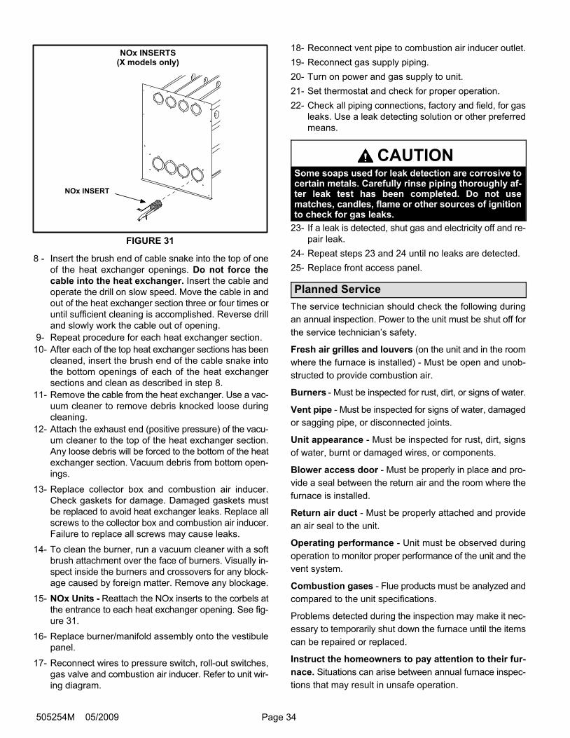
Page 34505254M 05/2009
NOx INSERTS(X models only)
FIGURE 31
NOx INSERT
8 − Insert the brush end of cable snake into the top of one
of the heat exchanger openings. Do not force the
cable into the heat exchanger. Insert the cable and
operate the drill on slow speed. Move the cable in and
out of the heat exchanger section three or four times or
until sufficient cleaning is accomplished. Reverse drill
and slowly work the cable out of opening.
9− Repeat procedure for each heat exchanger section.
10− After each of the top heat exchanger sections has been
cleaned, insert the brush end of the cable snake into
the bottom openings of each of the heat exchanger
sections and clean as described in step 8.
11− Remove the cable from the heat exchanger. Use a vac-
uum cleaner to remove debris knocked loose during
cleaning.
12− Attach the exhaust end (positive pressure) of the vacu-
um cleaner to the top of the heat exchanger section.
Any loose debris will be forced to the bottom of the heat
exchanger section. Vacuum debris from bottom open-
ings.
13− Replace collector box and combustion air inducer.
Check gaskets for damage. Damaged gaskets must
be replaced to avoid heat exchanger leaks. Replace all
screws to the collector box and combustion air inducer.
Failure to replace all screws may cause leaks.
14− To clean the burner, run a vacuum cleaner with a soft
brush attachment over the face of burners. Visually in-
spect inside the burners and crossovers for any block-
age caused by foreign matter. Remove any blockage.
15− NOx Units − Reattach the NOx inserts to the corbels at
the entrance to each heat exchanger opening. See fig-
ure 31.
16− Replace burner/manifold assembly onto the vestibule
panel.
17− Reconnect wires to pressure switch, roll−out switches,
gas valve and combustion air inducer. Refer to unit wir-
ing diagram.
18− Reconnect vent pipe to combustion air inducer outlet.
19− Reconnect gas supply piping.
20− Turn on power and gas supply to unit.
21− Set thermostat and check for proper operation.
22− Check all piping connections, factory and field, for gas
leaks. Use a leak detecting solution or other preferred
means.
CAUTIONSome soaps used for leak detection are corrosive tocertain metals. Carefully rinse piping thoroughly af-ter leak test has been completed. Do not usematches, candles, flame or other sources of ignitionto check for gas leaks.
23− If a leak is detected, shut gas and electricity off and re-
pair leak.
24− Repeat steps 23 and 24 until no leaks are detected.
25− Replace front access panel.
Planned Service
The service technician should check the following during
an annual inspection. Power to the unit must be shut off for
the service technician’s safety.
Fresh air grilles and louvers (on the unit and in the room
where the furnace is installed) − Must be open and unob-
structed to provide combustion air.
Burners − Must be inspected for rust, dirt, or signs of water.
Vent pipe − Must be inspected for signs of water, damaged
or sagging pipe, or disconnected joints.
Unit appearance − Must be inspected for rust, dirt, signs
of water, burnt or damaged wires, or components.
Blower access door − Must be properly in place and pro-
vide a seal between the return air and the room where the
furnace is installed.
Return air duct − Must be properly attached and provide
an air seal to the unit.
Operating performance − Unit must be observed during
operation to monitor proper performance of the unit and the
vent system.
Combustion gases − Flue products must be analyzed and
compared to the unit specifications.
Problems detected during the inspection may make it nec-
essary to temporarily shut down the furnace until the items
can be repaired or replaced.
Instruct the homeowners to pay attention to their fur-
nace. Situations can arise between annual furnace inspec-
tions that may result in unsafe operation.
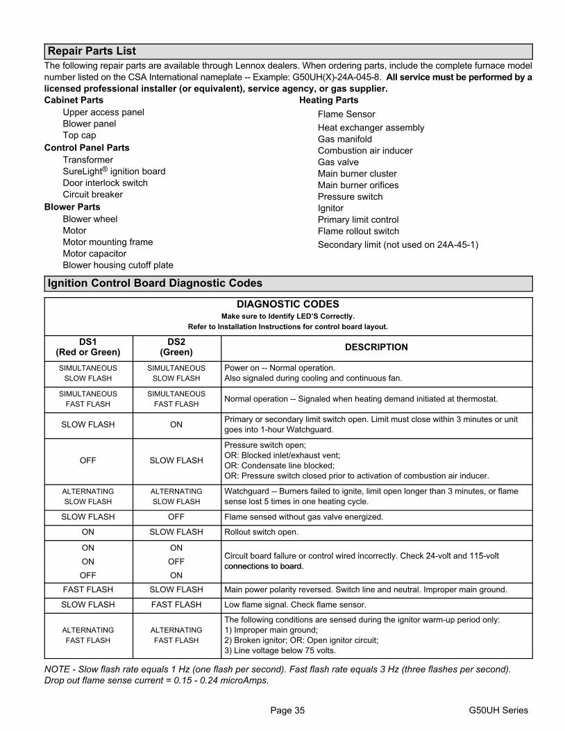
Page 35 G50UH Series
Repair Parts List
The following repair parts are available through Lennox dealers. When ordering parts, include the complete furnace model
number listed on the CSA International nameplate −− Example: G50UH(X)−24A−045−8. All service must be performed by a
licensed professional installer (or equivalent), service agency, or gas supplier.
Cabinet Parts
Upper access panel
Blower panel
Top cap
Control Panel Parts
Transformer
SureLight® ignition board
Door interlock switch
Circuit breaker
Blower Parts
Blower wheel
Motor
Motor mounting frame
Motor capacitor
Blower housing cutoff plate
Heating Parts
Flame Sensor
Heat exchanger assembly
Gas manifold
Combustion air inducer
Gas valve
Main burner cluster
Main burner orifices
Pressure switch
Ignitor
Primary limit control
Flame rollout switch
Secondary limit (not used on 24A−45−1)
Ignition Control Board Diagnostic Codes
DIAGNOSTIC CODESMake sure to Identify LED’S Correctly.
Refer to Installation Instructions for control board layout.
DS1(Red or Green)
DS2(Green)
DESCRIPTION
SIMULTANEOUS
SLOW FLASH
SIMULTANEOUS
SLOW FLASH
Power on −− Normal operation.
Also signaled during cooling and continuous fan.
SIMULTANEOUS
FAST FLASH
SIMULTANEOUS
FAST FLASHNormal operation −− Signaled when heating demand initiated at thermostat.
SLOW FLASH ONPrimary or secondary limit switch open. Limit must close within 3 minutes or unit
goes into 1−hour Watchguard.
OFF SLOW FLASH
Pressure switch open;
OR: Blocked inlet/exhaust vent;
OR: Condensate line blocked;
OR: Pressure switch closed prior to activation of combustion air inducer.
ALTERNATING
SLOW FLASH
ALTERNATING
SLOW FLASH
Watchguard −− Burners failed to ignite, limit open longer than 3 minutes, or flame
sense lost 5 times in one heating cycle.
SLOW FLASH OFF Flame sensed without gas valve energized.
ON SLOW FLASH Rollout switch open.
ON ONCirc it board fail re or control ired incorrectl Check 24 olt and 115 olt
ON OFFCircuit board failure or control wired incorrectly. Check 24−volt and 115−volt
connections to board.OFF ON
connections to board.
FAST FLASH SLOW FLASH Main power polarity reversed. Switch line and neutral. Improper main ground.
SLOW FLASH FAST FLASH Low flame signal. Check flame sensor.
ALTERNATING
FAST FLASH
ALTERNATING
FAST FLASH
The following conditions are sensed during the ignitor warm−up period only:
1) Improper main ground;
2) Broken ignitor; OR: Open ignitor circuit;
3) Line voltage below 75 volts.
NOTE − Slow flash rate equals 1 Hz (one flash per second). Fast flash rate equals 3 Hz (three flashes per second).
Drop out flame sense current = 0.15 − 0.24 microAmps.
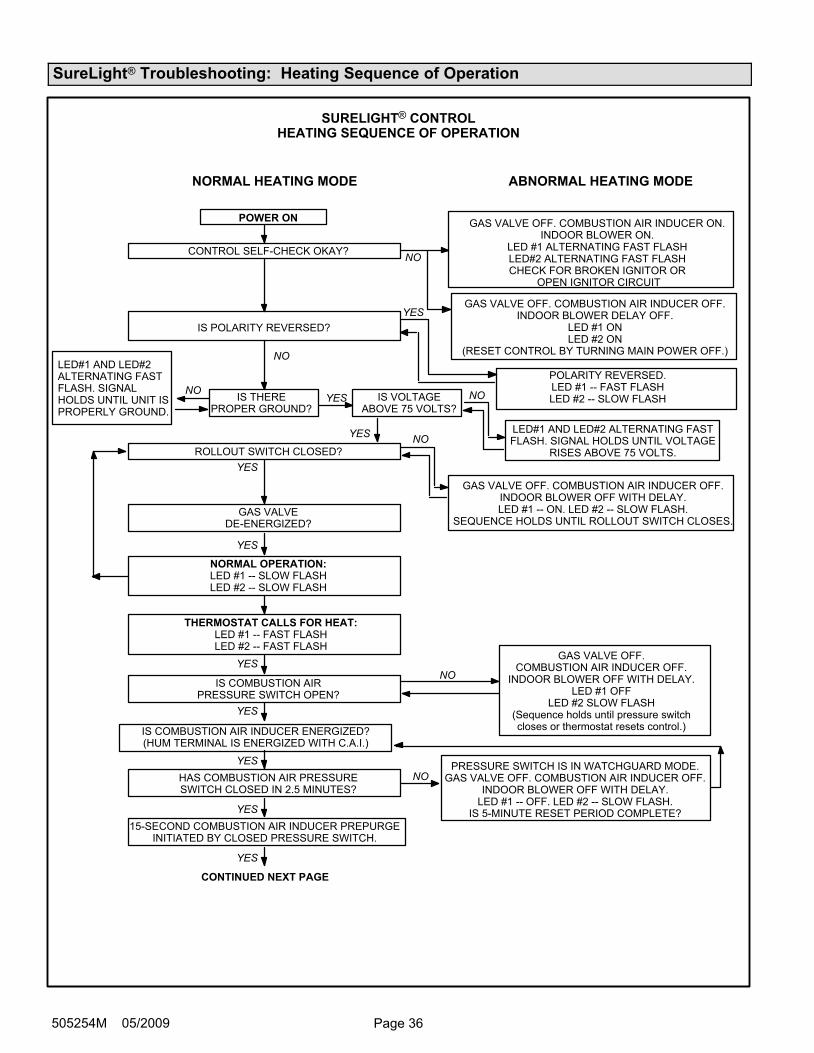
Page 36505254M 05/2009
SureLight® Troubleshooting: Heating Sequence of Operation
GAS VALVEDE−ENERGIZED?
SURELIGHT® CONTROLHEATING SEQUENCE OF OPERATION
NORMAL HEATING MODE ABNORMAL HEATING MODE
CONTROL SELF−CHECK OKAY?
NORMAL OPERATION:LED #1 −− SLOW FLASHLED #2 −− SLOW FLASH
YES
YES
YES
GAS VALVE OFF. COMBUSTION AIR INDUCER OFF.INDOOR BLOWER DELAY OFF.
LED #1 ONLED #2 ON
(RESET CONTROL BY TURNING MAIN POWER OFF.)
POLARITY REVERSED.LED #1 −− FAST FLASHLED #2 −− SLOW FLASH
POWER ON
IS POLARITY REVERSED?
ROLLOUT SWITCH CLOSED?
THERMOSTAT CALLS FOR HEAT:LED #1 −− FAST FLASHLED #2 −− FAST FLASH
IS COMBUSTION AIRPRESSURE SWITCH OPEN?
GAS VALVE OFF. COMBUSTION AIR INDUCER OFF.INDOOR BLOWER OFF WITH DELAY.LED #1 −− ON. LED #2 −− SLOW FLASH.
SEQUENCE HOLDS UNTIL ROLLOUT SWITCH CLOSES.
GAS VALVE OFF.COMBUSTION AIR INDUCER OFF.
INDOOR BLOWER OFF WITH DELAY.LED #1 OFF
LED #2 SLOW FLASH(Sequence holds until pressure switchcloses or thermostat resets control.)
NO
NOYES
NO
IS THEREPROPER GROUND?
IS VOLTAGEABOVE 75 VOLTS?
LED#1 AND LED#2 ALTERNATING FASTFLASH. SIGNAL HOLDS UNTIL VOLTAGE
RISES ABOVE 75 VOLTS.
NOYESNO
NO
IS COMBUSTION AIR INDUCER ENERGIZED?(HUM TERMINAL IS ENERGIZED WITH C.A.I.)
HAS COMBUSTION AIR PRESSURESWITCH CLOSED IN 2.5 MINUTES?
YES
YESPRESSURE SWITCH IS IN WATCHGUARD MODE.
GAS VALVE OFF. COMBUSTION AIR INDUCER OFF.INDOOR BLOWER OFF WITH DELAY.
LED #1 −− OFF. LED #2 −− SLOW FLASH.IS 5-MINUTE RESET PERIOD COMPLETE?
NO
15-SECOND COMBUSTION AIR INDUCER PREPURGEINITIATED BY CLOSED PRESSURE SWITCH.
YES
YES
CONTINUED NEXT PAGE
YES
GAS VALVE OFF. COMBUSTION AIR INDUCER ON.INDOOR BLOWER ON.
LED #1 ALTERNATING FAST FLASHLED#2 ALTERNATING FAST FLASHCHECK FOR BROKEN IGNITOR OR
OPEN IGNITOR CIRCUIT
LED#1 AND LED#2ALTERNATING FASTFLASH. SIGNALHOLDS UNTIL UNIT ISPROPERLY GROUND.
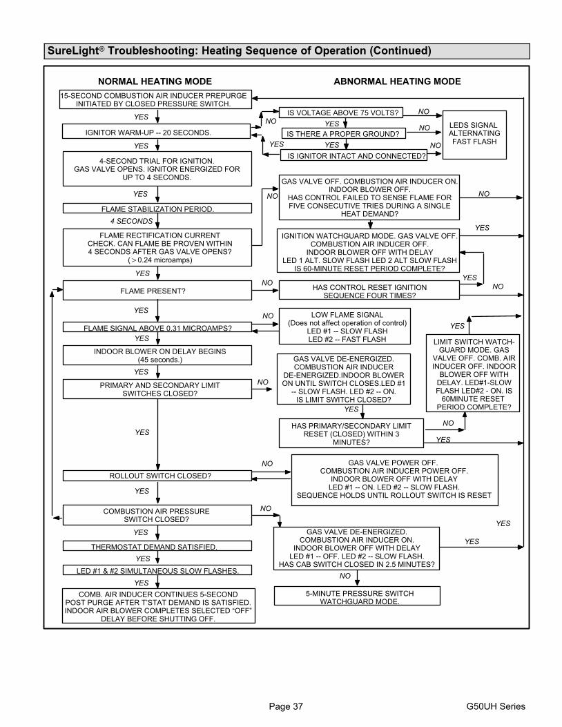
Page 37 G50UH Series
SureLight® Troubleshooting: Heating Sequence of Operation (Continued)
FLAME SIGNAL ABOVE 0.31 MICROAMPS?
LIMIT SWITCH WATCH-GUARD MODE. GAS
VALVE OFF. COMB. AIRINDUCER OFF. INDOOR
BLOWER OFF WITHDELAY. LED#1−SLOWFLASH LED#2 − ON. IS
60MINUTE RESET PERIOD COMPLETE?
NORMAL HEATING MODE ABNORMAL HEATING MODE
FLAME RECTIFICATION CURRENTCHECK. CAN FLAME BE PROVEN WITHIN4 SECONDS AFTER GAS VALVE OPENS?
(�0.24 microamps)
FLAME PRESENT?
INDOOR BLOWER ON DELAY BEGINS(45 seconds.)
PRIMARY AND SECONDARY LIMITSWITCHES CLOSED?
COMBUSTION AIR PRESSURESWITCH CLOSED?
LOW FLAME SIGNAL(Does not affect operation of control)
LED #1 −− SLOW FLASHLED #2 −− FAST FLASH
GAS VALVE DE−ENERGIZED.COMBUSTION AIR INDUCER
DE−ENERGIZED.INDOOR BLOWERON UNTIL SWITCH CLOSES.LED #1
−− SLOW FLASH. LED #2 −− ON.IS LIMIT SWITCH CLOSED?
GAS VALVE DE−ENERGIZED.COMBUSTION AIR INDUCER ON.
INDOOR BLOWER OFF WITH DELAYLED #1 −− OFF. LED #2 −− SLOW FLASH.
HAS CAB SWITCH CLOSED IN 2.5 MINUTES?
15-SECOND COMBUSTION AIR INDUCER PREPURGEINITIATED BY CLOSED PRESSURE SWITCH.
YES
IGNITOR WARM-UP −− 20 SECONDS.
YES
4-SECOND TRIAL FOR IGNITION.GAS VALVE OPENS. IGNITOR ENERGIZED FOR
UP TO 4 SECONDS.
YES
FLAME STABILIZATION PERIOD.
GAS VALVE OFF. COMBUSTION AIR INDUCER ON.INDOOR BLOWER OFF.
HAS CONTROL FAILED TO SENSE FLAME FORFIVE CONSECUTIVE TRIES DURING A SINGLE
HEAT DEMAND?
IGNITION WATCHGUARD MODE. GAS VALVE OFF.COMBUSTION AIR INDUCER OFF.
INDOOR BLOWER OFF WITH DELAYLED 1 ALT. SLOW FLASH LED 2 ALT SLOW FLASH
IS 60-MINUTE RESET PERIOD COMPLETE?
YES
4 SECONDS
YES
HAS CONTROL RESET IGNITIONSEQUENCE FOUR TIMES?
YES
YES
HAS PRIMARY/SECONDARY LIMITRESET (CLOSED) WITHIN 3
MINUTES?
YES
ROLLOUT SWITCH CLOSED?
GAS VALVE POWER OFF. COMBUSTION AIR INDUCER POWER OFF.
INDOOR BLOWER OFF WITH DELAYLED #1 −− ON. LED #2 −− SLOW FLASH.
SEQUENCE HOLDS UNTIL ROLLOUT SWITCH IS RESET
YES
THERMOSTAT DEMAND SATISFIED.
LED #1 & #2 SIMULTANEOUS SLOW FLASHES.
COMB. AIR INDUCER CONTINUES 5-SECONDPOST PURGE AFTER T’STAT DEMAND IS SATISFIED.INDOOR AIR BLOWER COMPLETES SELECTED �OFF"
DELAY BEFORE SHUTTING OFF.
YES
NO
5-MINUTE PRESSURE SWITCHWATCHGUARD MODE.
YES
IS THERE A PROPER GROUND?
IS VOLTAGE ABOVE 75 VOLTS?
IS IGNITOR INTACT AND CONNECTED?
LEDS SIGNAL ALTERNATINGFAST FLASH
NO YES
YESYES
YES
YES
NO
NO
NO
NO
NO
NO
NO
NO
YES
YES
NO
NO
NO
NO
YES
YES
YES
YES
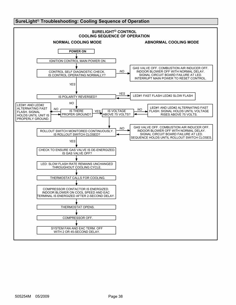
Page 38505254M 05/2009
SureLight® Troubleshooting: Cooling Sequence of Operation
SYSTEM FAN AND EAC TERM. OFFWITH 2 OR 45-SECOND DELAY.
SURELIGHT® CONTROLCOOLING SEQUENCE OF OPERATION
NORMAL COOLING MODE ABNORMAL COOLING MODE
IGNITION CONTROL MAIN POWER ON.
CONTROL SELF DIAGNOSTIC CHECK.IS CONTROL OPERATING NORMALLY?
YES
POWER ON
GAS VALVE OFF. COMBUSTION AIR INDUCER OFF.INDOOR BLOWER OFF WITH NORMAL DELAY.
SIGNAL CIRCUIT BOARD FAILURE AT LED.INTERRUPT MAIN POWER TO RESET CONTROL.
YESIS POLARITY REVERSED?
ROLLOUT SWITCH MONITORED CONTINUOUSLY.IS ROLLOUT SWITCH CLOSED?
CHECK TO ENSURE GAS VALVE IS DE−ENERGIZED.IS GAS VALVE OFF?
LED: SLOW FLASH RATE REMAINS UNCHANGEDTHROUGHOUT COOLING CYCLE.
THERMOSTAT CALLS FOR COOLING.
COMPRESSOR CONTACTOR IS ENERGIZED.INDOOR BLOWER ON COOL SPEED AND EAC
TERMINAL IS ENERGIZED AFTER 2-SECOND DELAY.
COMPRESSOR OFF.
THERMOSTAT OPENS.
NO
YES
NO
GAS VALVE OFF. COMBUSTION AIR INDUCER OFF.INDOOR BLOWER OFF WITH NORMAL DELAY.
SIGNAL CIRCUIT BOARD FAILURE AT LED.SEQUENCE HOLDS UNTIL ROLLOUT SWITCH CLOSES.
NO
IS THEREPROPER GROUND?
IS VOLTAGEABOVE 75 VOLTS?
NOYES
NO
LED#1 AND LED#2ALTERNATING FASTFLASH. SIGNALHOLDS UNTIL UNIT ISPROPERLY GROUND.
LED#1 AND LED#2 ALTERNATING FASTFLASH. SIGNAL HOLDS UNTIL VOLTAGE
RISES ABOVE 75 VOLTS.
LED#1 FAST FLASH LED#2 SLOW FLASH

Page 39 G50UH Series
SureLight® Troubleshooting: Continuous Fan Sequence of Operation
SURELIGHT® CONTROLCONTINUOUS FAN SEQUENCE OF OPERATION
LED: SLOW FLASH RATE REMAINSUNCHANGED THROUGHOUT SEQUENCE.
MANUAL FAN SELECTION MADE AT THERMOSTAT.CONTROL (G) ENERGIZES INDOOR BLOWER AT
FAN SPEED. EAC TERM. IS ENERGIZED.
THERMOSTAT CALLS FOR HEAT (W).
THERMOSTAT CALLS FOR COOLING.
THERMOSTAT OPENS. COMBUSTION AIR INDUCERAND HUM TERMINAL ARE DE−ENERGIZED.
INDOOR BLOWER SWITCHES TO COOL SPEED.
THERMOSTAT OPENS.
INDOOR BLOWER SWITCHES TO FANSPEED. EAC TERM. REMAINS ENERGIZED.
NO YES
YES
NO
HUM TERM. ENERGIZESWITH COMB. AIR INDUCER.
INDOOR BLOWER SWITCHES TO HEAT SPEEDAFTER NORMAL DELAY.
INDOOR BLOWER SELECTED TIME OFF DELAY BEGINS.AFTER DELAY HEAT SPEED DE−ENERGIZED.
(blower remains energized during continuous fan mode).
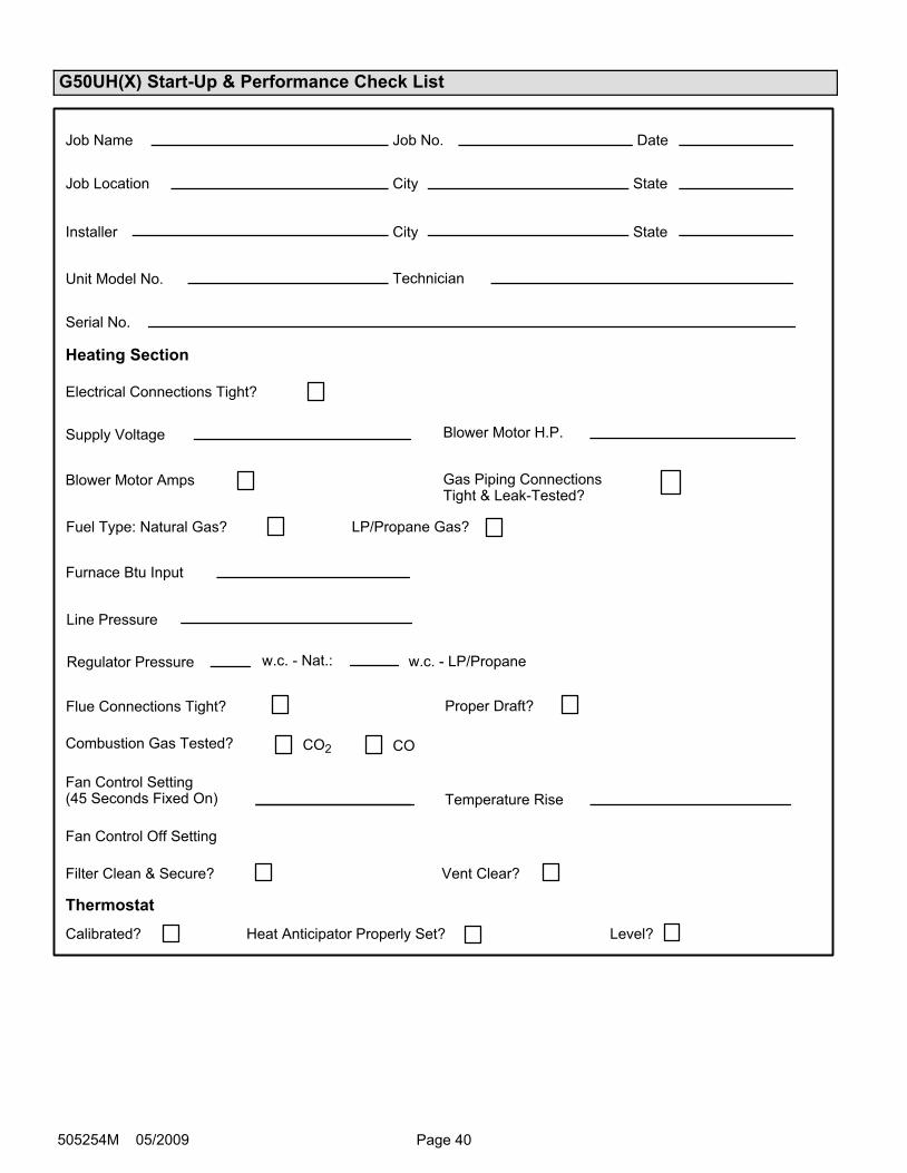
Page 40505254M 05/2009
G50UH(X) Start−Up & Performance Check List
w.c. − LP/Propane
Filter Clean & Secure?
Supply Voltage
Electrical Connections Tight?
Job Name
Job Location
Installer
Unit Model No.
Furnace Btu Input
Line Pressure
Job No.
City
City
Serial No.
Date
State
Technician
Flue Connections Tight?
Heating Section
Thermostat
Calibrated? Heat Anticipator Properly Set? Level?
Fuel Type: Natural Gas?
Blower Motor Amps
Blower Motor H.P.
Gas Piping ConnectionsTight & Leak−Tested?
Proper Draft?
Vent Clear?
State
Temperature Rise
Fan Control Off Setting
Fan Control Setting(45 Seconds Fixed On)
Regulator Pressure w.c. − Nat.:
LP/Propane Gas?
Combustion Gas Tested? CO2 CO