Embed Size (px)
Citation preview
1
48VR---A, 48VR---C and 48VR---EPerformancet 15 SEER 2---Stage PackagedHYBRID HEATR Dual Fuel System with Puron(R---410A) RefrigerantSingle and Three Phase2---5 Nominal Tons (Sizes 24---60)
Installation Instructions,IMPORTANT: Effective January 1, 2015, all split system andpackaged air conditioners must be installed pursuant to applicableregional efficiency standards issued by the Department of Energy.NOTE: Read the entire instruction manual before starting theinstallation.NOTE: Installer: Make sure the Owner’s Manual and ServiceInstructions are left with the unit after installation.
TABLE OF CONTENTSPAGE
SAFETY CONSIDERATIONS 1. . . . . . . . . . . . . . . . . . . . . . . . .INTRODUCTION 2. . . . . . . . . . . . . . . . . . . . . . . . . . . . . . . . . . .RECEIVING AND INSTALLATION 2--14. . . . . . . . . . . . . . . . .Check Equipment 2. . . . . . . . . . . . . . . . . . . . . . . . . . . . . . . . . .Identify Unit 2. . . . . . . . . . . . . . . . . . . . . . . . . . . . . . . . . . . .Inspect Shipment 2. . . . . . . . . . . . . . . . . . . . . . . . . . . . . . . . .
Provide Unit Support 2. . . . . . . . . . . . . . . . . . . . . . . . . . . . . . .Roof Curb 2. . . . . . . . . . . . . . . . . . . . . . . . . . . . . . . . . . . . . .Slab Mount 3. . . . . . . . . . . . . . . . . . . . . . . . . . . . . . . . . . . . .
Field Fabricate Ductwork 3. . . . . . . . . . . . . . . . . . . . . . . . . . . .Provide Clearances 3. . . . . . . . . . . . . . . . . . . . . . . . . . . . . . . . .Rig and Place Unit 3. . . . . . . . . . . . . . . . . . . . . . . . . . . . . . . . .Inspection 3. . . . . . . . . . . . . . . . . . . . . . . . . . . . . . . . . . . . . .Rigging/Lifting of Unit 4. . . . . . . . . . . . . . . . . . . . . . . . . . . .
Connect Condensate Drain 10. . . . . . . . . . . . . . . . . . . . . . . . . .Install Flue Hood 10. . . . . . . . . . . . . . . . . . . . . . . . . . . . . . . . . .Install Gas Piping 11. . . . . . . . . . . . . . . . . . . . . . . . . . . . . . . . .Install Duct Connections 12. . . . . . . . . . . . . . . . . . . . . . . . . . . .Configuring Units for Downflow (Vertical)Discharge 12. . . . . . . . . . . . . . . . . . . . . . . . . . . . . . . . . . . . .
Install Electrical Connections 13. . . . . . . . . . . . . . . . . . . . . . . .High--Voltage Connections 13. . . . . . . . . . . . . . . . . . . . . . . .Special Procedures for 208--V Operation 13. . . . . . . . . . . . . .Control Voltage Connections 13. . . . . . . . . . . . . . . . . . . . . . .Standard Connection 14. . . . . . . . . . . . . . . . . . . . . . . . . . . . .Heat Anticipator Setting 14. . . . . . . . . . . . . . . . . . . . . . . . . .Transformer Protection 14. . . . . . . . . . . . . . . . . . . . . . . . . . .
PRE--START--UP 14. . . . . . . . . . . . . . . . . . . . . . . . . . . . . . . . . . .START--UP 15--27. . . . . . . . . . . . . . . . . . . . . . . . . . . . . . . . . . . . .Check for Refrigerant Leaks 15. . . . . . . . . . . . . . . . . . . . . . . . .Start--Up Heating & Make Adjustments 15. . . . . . . . . . . . . . . .Check Heating Control 16. . . . . . . . . . . . . . . . . . . . . . . . . . .Check Gas Input 16. . . . . . . . . . . . . . . . . . . . . . . . . . . . . . . .Adjust Gas Input 16. . . . . . . . . . . . . . . . . . . . . . . . . . . . . . . .Check Burner Flame 17. . . . . . . . . . . . . . . . . . . . . . . . . . . . .Normal Operation 25. . . . . . . . . . . . . . . . . . . . . . . . . . . . . . .Airflow and Temperature Rise 25. . . . . . . . . . . . . . . . . . . . . .Heating Sequence of Operation 25. . . . . . . . . . . . . . . . . . . . .Limit Switches 25. . . . . . . . . . . . . . . . . . . . . . . . . . . . . . . . .Rollout Switch 25. . . . . . . . . . . . . . . . . . . . . . . . . . . . . . . . .
A09033
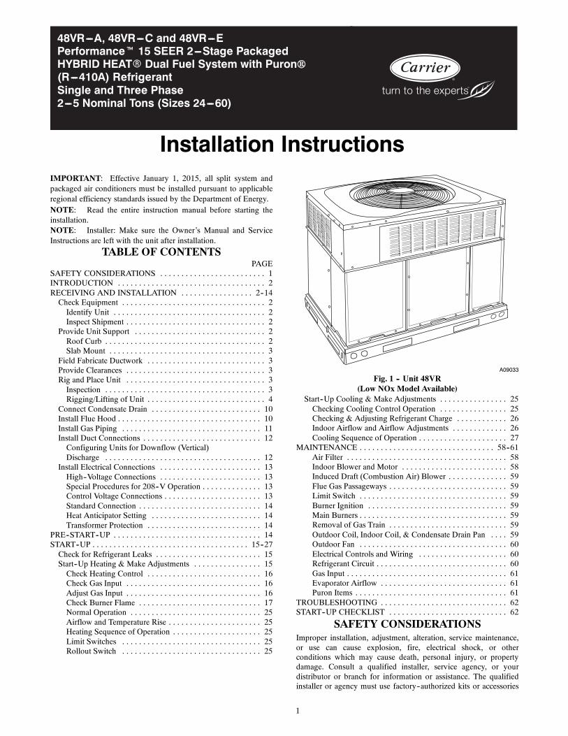
Fig. 1 -- Unit 48VR(Low NOx Model Available)
Start--Up Cooling & Make Adjustments 25. . . . . . . . . . . . . . . .Checking Cooling Control Operation 25. . . . . . . . . . . . . . . .Checking & Adjusting Refrigerant Charge 26. . . . . . . . . . . .Indoor Airflow and Airflow Adjustments 26. . . . . . . . . . . . .Cooling Sequence of Operation 27. . . . . . . . . . . . . . . . . . . . .
MAINTENANCE 58--61. . . . . . . . . . . . . . . . . . . . . . . . . . . . . . . .Air Filter 58. . . . . . . . . . . . . . . . . . . . . . . . . . . . . . . . . . . . . .Indoor Blower and Motor 58. . . . . . . . . . . . . . . . . . . . . . . . .Induced Draft (Combustion Air) Blower 59. . . . . . . . . . . . . .Flue Gas Passageways 59. . . . . . . . . . . . . . . . . . . . . . . . . . . .Limit Switch 59. . . . . . . . . . . . . . . . . . . . . . . . . . . . . . . . . . .Burner Ignition 59. . . . . . . . . . . . . . . . . . . . . . . . . . . . . . . . .Main Burners 59. . . . . . . . . . . . . . . . . . . . . . . . . . . . . . . . . . .Removal of Gas Train 59. . . . . . . . . . . . . . . . . . . . . . . . . . . .Outdoor Coil, Indoor Coil, & Condensate Drain Pan 59. . . .Outdoor Fan 60. . . . . . . . . . . . . . . . . . . . . . . . . . . . . . . . . . .Electrical Controls and Wiring 60. . . . . . . . . . . . . . . . . . . . .Refrigerant Circuit 60. . . . . . . . . . . . . . . . . . . . . . . . . . . . . . .Gas Input 61. . . . . . . . . . . . . . . . . . . . . . . . . . . . . . . . . . . . . .Evaporator Airflow 61. . . . . . . . . . . . . . . . . . . . . . . . . . . . . .Puron Items 61. . . . . . . . . . . . . . . . . . . . . . . . . . . . . . . . . . . .
TROUBLESHOOTING 62. . . . . . . . . . . . . . . . . . . . . . . . . . . . . .START--UP CHECKLIST 62. . . . . . . . . . . . . . . . . . . . . . . . . . . .
SAFETY CONSIDERATIONSImproper installation, adjustment, alteration, service maintenance,or use can cause explosion, fire, electrical shock, or otherconditions which may cause death, personal injury, or propertydamage. Consult a qualified installer, service agency, or yourdistributor or branch for information or assistance. The qualifiedinstaller or agency must use factory--authorized kits or accessories
2
when modifying this product. Refer to the individual instructionspackaged with the kits or accessories when installing.
Follow all safety codes. Wear safety glasses, protective clothing,and work gloves. Have a fire extinguisher available. Read theseinstructions thoroughly and follow all warnings or cautionsincluded in literature and attached to the unit. consult localbuilding codes, the current editions of the National Fuel Gas Code(NFGC) NFPA 54/ANSI Z223.1, and the National Electrical Code(NEC) NFPA 70.In Canada refer to the current editions of the National Standards ofCanada CAN/CSA--B149.1 and .2 Natural Gas and PropaneInstallation codes, and Canadian Electrical Code CSA C22.1
Recognize safety information. This is the safety--alert symbol .When you see this symbol on the unit and in instructions or manu-als, be alert to the potential for personal injury. Understand thesesignal words: DANGER, WARNING, and CAUTION. Thesewords are used with the safety--alert symbol. DANGER identifiesthe most serious hazards which will result in severe personal injuryor death. WARNING signifies hazards which could result in per-sonal injury or death. CAUTION is used to identify unsafe practic-es which may result in minor personal injury or product and prop-erty damage. NOTE is used to highlight suggestions which willresult in enhanced installation, reliability, or operation.
ELECTRICAL SHOCK HAZARD
Failure to follow this warning could result in personalinjury or death.
Before installing or servicing system, always turn off mainpower to system and install lockout tag. There may bemore than one disconnect switch. Turn off accessory heaterpower switch if applicable.
! WARNING
PERSONAL INJURY AND ENVIRONMENTALHAZARD
Failure to relieve system pressure could result in personalinjury and/or death.
1. Relieve pressure and recover all refrigerant beforeservicing existing equipment, and before final unit disposal.Use all service ports and open all flow--control devices,including solenoid valves.2. Federal regulations require that you do not ventrefrigerant into the atmosphere. Recover during systemrepair or final unit disposal.
! WARNING
FIRE, EXPLOSION, ELECTRICAL SHOCK ANDCARBON MONOXIDE POISONING HAZARD
Failure to follow this warning could result in personalinjury or unit damage.
A qualified installer or agency must use onlyfactory--authorized kits or accessories when modifying thisproduct.
WARNING!
CUT HAZARD
Failure to follow this caution may result in personal injury.
When removing access panels (see Fig. 17) or performingmaintenance functions inside your unit, be aware of sharpsheet metal parts and screws. Although special care is takento reduce sharp edges to a minimum, be extremely carefuland wear appropriate protective clothing, safety glasses andgloves when handling parts or reaching into the unit.
! CAUTION
INTRODUCTIONThis unit (see Fig. 1) is a fully self--contained, combinationCategory I gas heating/electric heating and cooling unit designedfor outdoor installation (See Fig. 3 and 4 for unit dimensions). Allunit sizes have return and discharge openings for both horizontaland downflow configurations, and are factory shipped with alldownflow duct openings covered. Units may be installed either ona rooftop or on a cement slab. (See Fig. 5 for roof curbdimensions).In gas heating mode, this unit is designed for a minimumcontinuous return--air temperature of 55_F (13_C) db and amaximum continuous return--air temperature of 80_F (27_C) db.Failure to follow these return--air temperature limits may affectreliability of heat exchangers, motors, and other components.Models with an N in the fifth position of the model number arededicated Low NOx units designed for California installations.These models meet the California maximum oxides of nitrogen(NOx) emissions requirements of 40 nanograms/joule or less asshipped from the factory and must be installed in California AirQuality Management Districts or any other regions in NorthAmerica where a Low NOx rule exists.NOTE: Low NOx requirements apply only to natural gasinstallations.
RECEIVING AND INSTALLATIONStep 1 — Check EquipmentIdentify UnitThe unit model number and serial number are stamped on the unitinformation plate. Check this information against shipping papers.Inspect ShipmentInspect for shipping damage before removing packaging materials.If unit appears to be damaged or is torn loose from its anchorage,have it examined by transportation inspectors before removal.Forward claim papers directly to transportation company.Manufacturer is not responsible for any damage incurred in transit.Check all items against shipping list. Immediately notify thenearest equipment distribution office if any item is missing. Toprevent loss or damage, leave all parts in original packages untilinstallation.If the unit is to be mounted on a curb in a downflow application,review Step 9 to determine which method is to be used to removethe downflow panels before rigging and lifting into place. Thepanel removal process may require the unit to be on the ground.
Step 2 — Provide Unit SupportFor hurricane tie downs, contact distributor for details and PE(Professional Engineering) Certificate if required.Roof CurbInstall accessory roof curb in accordance with instructions shippedwith curb (See Fig. 5). Install insulation, cant strips, roofing, andflashing. Ductwork must be attached to curb.IMPORTANT: The gasketing of the unit to the roof curb iscritical for a water tight seal. Install gasketing material suppliedwith the roof curb. Improperly applied gasketing also can result inair leaks and poor unit performance.
48VR
3
Curb should be level to within 1/4 in. (6 mm). This is necessaryfor unit drain to function properly. Refer to accessory roof curbinstallation instructions for additional information as required.Installation on older “G” series roof curbs.
Two accessory kits are available to aid in installing a new “G”series unit on an old “G” roof curb.
1. Accessory kit number CPADCURB001A00, (small chassis)and accessory kit number CPADCURB002A00, (largechassis) includes roof curb adapter and gaskets for theperimeter seal and duct openings. No additionalmodifications to the curb are required when using this kit.
2. An alternative to the adapter curb is to modify the existingcurb by removing the outer horizontal flange and useaccessory kit number CPGSKTKIT001A00 which includesspacer blocks (for easy alignment to existing curb) andgaskets for the perimeter seal and duct openings. This kit isused when existing curb is modified by removing outerhorizontal flange.
UNITS/STRUCTURAL DAMAGE HAZARD
Failure to follow this caution may result in propertydamage.
Ensure there is sufficient clearance for saw blade whencutting the outer horizontal flange of the roof curb so thereis no damage to the roof or flashing.
WARNING!
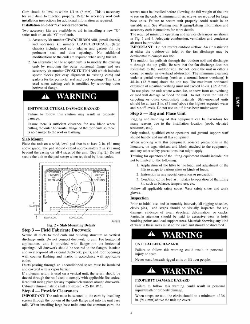
Slab MountPlace the unit on a solid, level pad that is at least 2 in. (51 mm)above grade. The pad should extend approximately 2 in. (51 mm)beyond the casing on all 4 sides of the unit. (See Fig. 2.) Do notsecure the unit to the pad except when required by local codes.
OPTIONALRETURN
AIROPENING
OPTIONALSUPPLY
AIROPENING
EVAP. COIL COND. COIL
2˝(50.8mm)
A07926
Fig. 2 -- Slab Mounting DetailsStep 3 — Field Fabricate DuctworkSecure all ducts to roof curb and building structure on verticaldischarge units. Do not connect ductwork to unit. For horizontalapplications, unit is provided with flanges on the horizontalopenings. All ductwork should be secured to the flanges. Insulateand weatherproof all external ductwork, joints, and roof openingswith counter flashing and mastic in accordance with applicablecodes.Ducts passing through an unconditioned space must be insulatedand covered with a vapor barrier.If a plenum return is used on a vertical unit, the return should beducted through the roof deck to comply with applicable fire codes.Read unit rating plate for any required clearances around ductwork.Cabinet return--air static shall not exceed --.25 IN. W.C.Step 4 — Provide ClearancesIMPORTANT: The unit must be secured to the curb by installingscrews through the bottom of the curb flange and into the unit baserails. When installing large base units onto the common curb, the
screws must be installed before allowing the full weight of the unitto rest on the curb. A minimum of six screws are required for largebase units. Failure to secure unit properly could result in anunstable unit. See Warning near Rigging/Lifting information andaccessory curb instructions for more details.The required minimum operating and service clearances are shownin Fig. 3 and 4. Adequate combustion, ventilation and condenserair must be provided.IMPORTANT: Do not restrict outdoor airflow. An air restrictionat either the outdoor--air inlet or the fan discharge may bedetrimental to compressor life.The outdoor fan pulls air through the outdoor coil and dischargesit through the top grille. Be sure that the fan discharge does notrecirculate to the outdoor coil. Do not locate the unit in either acorner or under an overhead obstruction. The minimum clearanceunder a partial overhang (such as a normal house overhang) is48--in. (1219 mm) above the unit top. The maximum horizontalextension of a partial overhang must not exceed 48--in. (1219 mm).Do not place the unit where water, ice, or snow from an overhangor roof will damage or flood the unit. Do not install the unit oncarpeting or other combustible materials. Slab--mounted unitsshould be at least 2 in. (51 mm) above the highest expected waterand runoff levels. Do not use unit if it has been under water.
Step 5 — Rig and Place UnitRigging and handling of this equipment can be hazardous formany reasons due to the installation location (roofs, elevatedstructures, etc.).
Only trained, qualified crane operators and ground support staffshould handle and install this equipment.
When working with this equipment, observe precautions in theliterature, on tags, stickers, and labels attached to the equipment,and any other safety precautions that might apply.
Training for operators of the lifting equipment should include, butnot be limited to, the following:
1. Application of the lifter to the load, and adjustment of thelifts to adapt to various sizes or kinds of loads.
2. Instruction in any special operation or precaution.3. Condition of the load as it relates to operation of the liftingkit, such as balance, temperature, etc.
Follow all applicable safety codes. Wear safety shoes and workgloves.
InspectionPrior to initial use, and at monthly intervals, all rigging shackles,clevis pins, and straps should be visually inspected for anydamage, evidence of wear, structural deformation, or cracks.Particular attention should be paid to excessive wear at hoisthooking points and load support areas. Materials showing any kindof wear in these areas must not be used and should be discarded.
UNIT FALLING HAZARD
Failure to follow this warning could result in personalinjury or death.
Never stand beneath rigged units or lift over people.
! WARNING
PROPERTY DAMAGE HAZARD
Failure to follow this warning could result in personalinjury/death or property damage.
When straps are taut, the clevis should be a minimum of 36in. (914 mm) above the unit top cover.
! WARNING
48VR
4
Rigging/Lifting of Unit (See Fig. 6)
UNIT FALLING HAZARD
Failure to follow this warning could result in personalinjury or death.
Large base units must be secured to common curb beforeallowing full weight of unit to rest on curb. Install screwsthrough curb into unit base rails while rigging crane is stillsupporting unit.
! WARNINGLifting holes are provided in base rails as shown in Fig. 3 and 4.
1. Leave top shipping skid on the unit for use as a spreader barto prevent the rigging straps from damaging the unit. If theskid is not available, use a spreader bar of sufficient lengthto protect the unit from damage.
2. Attach shackles, clevis pins, and straps to the base rails ofthe unit. Be sure materials are rated to hold the weight of theunit (See Fig. 6).
3. Attach a clevis of sufficient strength in the middle of thestraps. Adjust the clevis location to ensure unit is lifted levelwith the ground.
After the unit is placed on the roof curb or mounting pad, removethe top skid.
48VR
5
A190133
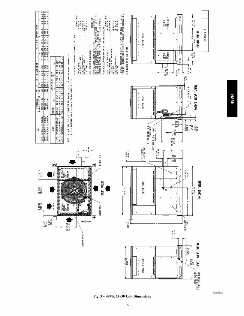
Fig. 3 -- 48VR 24--30 Unit Dimensions
48VR
6
A190134
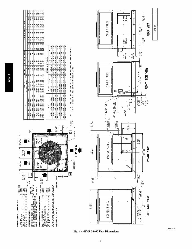
Fig. 4 -- 48VR 36--60 Unit Dimensions
48VR
7
RETURN AIR
SMALLBASE UNIT
SUPPLYAIR
LARGEBASE UNIT
UNIT PLACEMENT ON COMMON CURB
SMALL/COMMON CURB
SMALL OR LARGE BASE UNITLARGE CURBA180216
UNITSIZE
CATALOGNUMBER
AIN.(mm)
B (small / commonbase)
IN. (mm)*
B (largebase)
IN. (mm)*
CIN.(mm)
DIN.(mm)
EIN.(mm)
FIN.(mm)
GIN. (mm)
HIN. (mm)
Smallor
LargeCPRFCURB011B00 14
(356) 10 (254)14 (356) 16
(406)47.8
(1214)
32.4(822)
2.7 (69)30.6 (778)
46.1 (1170)
Large CPRFCURB013B00 14(356) 14 (356) 43.9
(1116) 42.2 (1072)
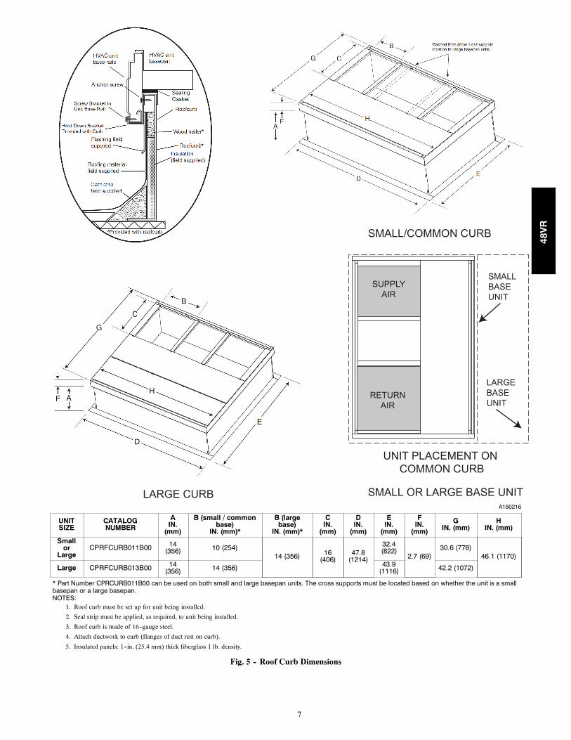
* Part Number CPRCURB011B00 can be used on both small and large basepan units. The cross supports must be located based on whether the unit is a smallbasepan or a large basepan.NOTES:
1. Roof curb must be set up for unit being installed.
2. Seal strip must be applied, as required, to unit being installed.
3. Roof curb is made of 16--gauge steel.
4. Attach ductwork to curb (flanges of duct rest on curb).
5. Insulated panels: 1--in. (25.4 mm) thick fiberglass 1 lb. density.
Fig. 5 -- Roof Curb Dimensions
48VR
8
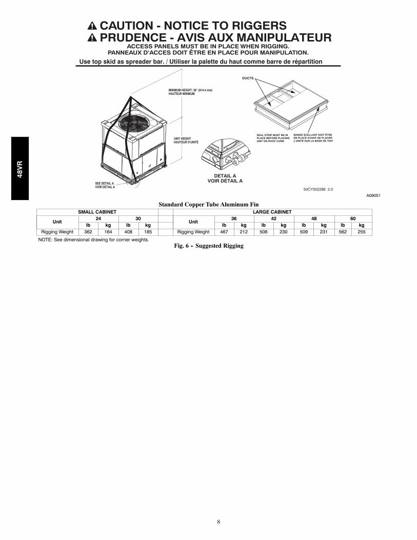
ACCESS PANELS MUST BE IN PLACE WHEN RIGGING.PANNEAUX D'ACCES DOIT ÊTRE EN PLACE POUR MANIPULATION.
50CY502286 2.0
CAUTION - NOTICE TO RIGGERSPRUDENCE - AVIS AUX MANIPULATEUR
Use top skid as spreader bar. / Utiliser la palette du haut comme barre de répartition
SEAL STRIP MUST BE INPLACE BEFORE PLACINGUNIT ON ROOF CURB
DUCTS
DETAIL AVOIR DÉTAIL A
MINIMUM HEIGHT: 36" (914.4 mm)HAUTEUR MINIMUM
UNIT HEIGHTHAUTEUR D'UNITÉ
SEE DETAIL AVOIR DÉTAIL A
BANDE SCELLANT DOIT ÊTRE EN PLACE AVANT DE PLACER L'UNITÉ SUR LA BASE DE TOIT
A09051
Standard Copper Tube Aluminum FinSMALL CABINET LARGE CABINET
Unit24 30
Unit36 42 48 60
lb kg lb kg lb kg lb kg lb kg lb kgRigging Weight 362 164 408 185 Rigging Weight 467 212 506 230 509 231 562 255
NOTE: See dimensional drawing for corner weights.Fig. 6 -- Suggested Rigging
48VR
9
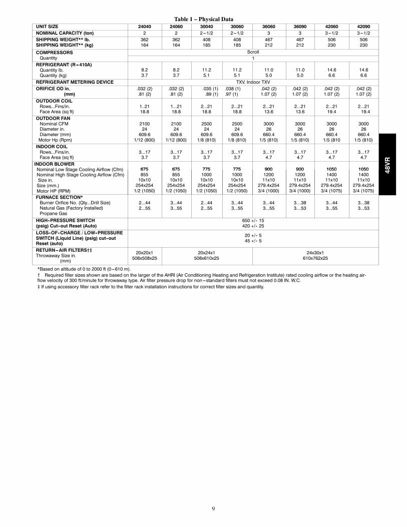
Table 1 – Physical DataUNIT SIZE 24040 24060 30040 30060 36060 36090 42060 42090NOMINAL CAPACITY (ton) 2 2 2---1/2 2---1/2 3 3 3---1/2 3---1/2SHIPPING WEIGHT** lb.SHIPPING WEIGHT** (kg)
362164
362164
408185
408185
467212
467212
506230
506230
COMPRESSORSQuantity
Scroll1
REFRIGERANT (R---410A)Quantity lb.Quantity (kg)
8.23.7
8.23.7
11.25.1
11.25.1
11.05.0
11.05.0
14.66.6
14.66.6
REFRIGERANT METERING DEVICE TXV, Indoor TXVORIFICE OD in.
(mm).032 (2).81 (2)
.032 (2).81 (2)
.035 (1) .038 (1).89 (1) .97 (1)
.042 (2)1.07 (2)
.042 (2)1.07 (2)
.042 (2)1.07 (2)
.042 (2)1.07 (2)
OUTDOOR COILRows...Fins/in.Face Area (sq ft)
1..2118.8
1...2118.8
2...2118.8
2...2118.8
2...2113.6
2...2113.6
2...2119.4
2...2119.4
OUTDOOR FANNominal CFMDiameter in.Diameter (mm)Motor Hp (Rpm)
210024609.6
1/12 (800)
210024609.6
1/12 (800)
250024609.61/8 (810)
250024609.61/8 (810)
300026660.41/5 (810)
300026660.41/5 (810)
300026660.41/5 (810
300026660.41/5 (810)
INDOOR COILRows...Fins/in.Face Area (sq ft)
3...173.7
3...173.7
3...173.7
3...173.7
3...174.7
3...174.7
3...174.7
3...174.7
INDOOR BLOWERNominal Low Stage Cooling Airflow (Cfm)Nominal High Stage Cooling Airflow (Cfm)Size in.Size (mm.)Motor HP (RPM)
675 675 775 775 900 900 1050 105067585510x10254x2541/2 (1050)
67585510x10254x2541/2 (1050)
775100010x10254x2541/2 (1050)
775100010x10254x2541/2 (1050)
900120011x10279.4x2543/4 (1000)
900120011x10279.4x2543/4 (1000)
1050140011x10279.4x2543/4 (1075)
1050140011x10279.4x2543/4 (1075)
FURNACE SECTION*Burner Orifice No. (Qty...Drill Size)Natural Gas (Factory Installed)Propane Gas
2...442...55
3...443...55
2...442...55
3...443...55
3...443...55
3…383…53
3...443...55
3...383...53
HIGH--PRESSURE SWITCH(psig) Cut--out Reset (Auto)
650 +/-- 15420 +/-- 25
LOSS--OF--CHARGE / LOW--PRESSURESWITCH (Liquid Line) (psig) cut--outReset (auto)
20 +/-- 545 +/-- 5
RETURN---AIR FILTERS†}Throwaway Size in.
(mm)
20x20x1508x508x25
20x24x1508x610x25
24x30x1610x762x25
*Based on altitude of 0 to 2000 ft (0---610 m).{ Required filter sizes shown are based on the larger of the AHRI (Air Conditioning Heating and Refrigeration Institute) rated cooling airflow or the heating air-flow velocity of 300 ft/minute for throwaway type. Air filter pressure drop for non---standard filters must not exceed 0.08 IN. W.C.} If using accessory filter rack refer to the filter rack installation instructions for correct filter sizes and quantity.
48VR
10
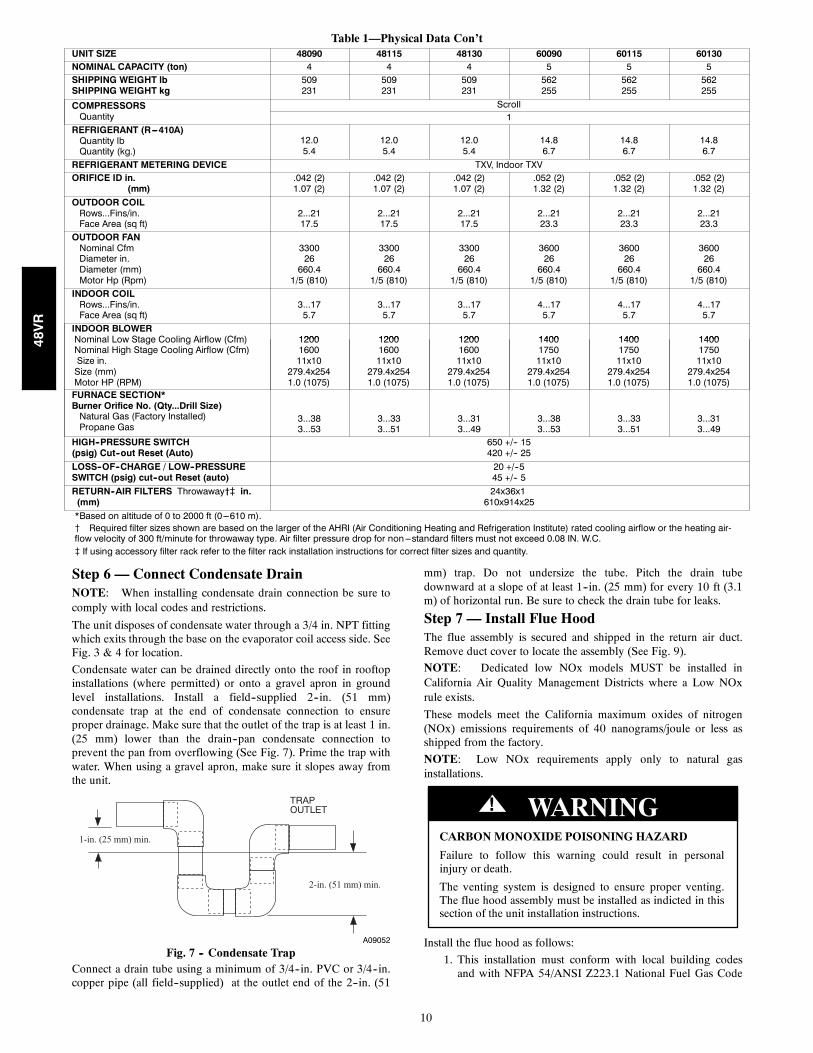
Table 1—Physical Data Con’tUNIT SIZE 48090 48115 48130 60090 60115 60130NOMINAL CAPACITY (ton) 4 4 4 5 5 5SHIPPING WEIGHT lbSHIPPING WEIGHT kg
509231
509231
509231
562255
562255
562255
COMPRESSORSQuantity
Scroll1
REFRIGERANT (R---410A)Quantity lbQuantity (kg.)
12.05.4
12.05.4
12.05.4
14.86.7
14.86.7
14.86.7
REFRIGERANT METERING DEVICE TXV, Indoor TXVORIFICE ID in.
(mm).042 (2)1.07 (2)
.042 (2)1.07 (2)
.042 (2)1.07 (2)
.052 (2)1.32 (2)
.052 (2)1.32 (2)
.052 (2)1.32 (2)
OUTDOOR COILRows...Fins/in.Face Area (sq ft)
2...2117.5
2...2117.5
2...2117.5
2...2123.3
2...2123.3
2...2123.3
OUTDOOR FANNominal CfmDiameter in.Diameter (mm)Motor Hp (Rpm)
330026660.41/5 (810)
330026660.41/5 (810)
330026660.41/5 (810)
360026660.41/5 (810)
360026660.41/5 (810)
360026660.41/5 (810)
INDOOR COILRows...Fins/in.Face Area (sq ft)
3...175.7
3...175.7
3...175.7
4...175.7
4...175.7
4...175.7
INDOOR BLOWERNominal Low Stage Cooling Airflow (Cfm)Nominal High Stage Cooling Airflow (Cfm)Size in.Size (mm)Motor HP (RPM)
1200 1200 1200 1400 1400 14001200160011x10279.4x2541.0 (1075)
1200160011x10279.4x2541.0 (1075)
1200160011x10279.4x2541.0 (1075)
1400175011x10279.4x2541.0 (1075)
1400175011x10279.4x2541.0 (1075)
1400175011x10279.4x2541.0 (1075)
FURNACE SECTION*Burner Orifice No. (Qty...Drill Size)Natural Gas (Factory Installed)Propane Gas
3...383...53
3...333...51
3...313...49
3...383...53
3...333...51
3...313...49
HIGH--PRESSURE SWITCH(psig) Cut--out Reset (Auto)
650 +/-- 15420 +/-- 25
LOSS--OF--CHARGE / LOW--PRESSURESWITCH (psig) cut--out Reset (auto)
20 +/--545 +/-- 5
RETURN--AIR FILTERS Throwaway†} in.(mm)
24x36x1610x914x25
*Based on altitude of 0 to 2000 ft (0---610 m).{ Required filter sizes shown are based on the larger of the AHRI (Air Conditioning Heating and Refrigeration Institute) rated cooling airflow or the heating air-flow velocity of 300 ft/minute for throwaway type. Air filter pressure drop for non---standard filters must not exceed 0.08 IN. W.C.} If using accessory filter rack refer to the filter rack installation instructions for correct filter sizes and quantity.
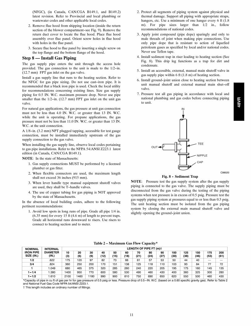
Step 6 — Connect Condensate DrainNOTE: When installing condensate drain connection be sure tocomply with local codes and restrictions.
The unit disposes of condensate water through a 3/4 in. NPT fittingwhich exits through the base on the evaporator coil access side. SeeFig. 3 & 4 for location.
Condensate water can be drained directly onto the roof in rooftopinstallations (where permitted) or onto a gravel apron in groundlevel installations. Install a field--supplied 2--in. (51 mm)condensate trap at the end of condensate connection to ensureproper drainage. Make sure that the outlet of the trap is at least 1 in.(25 mm) lower than the drain--pan condensate connection toprevent the pan from overflowing (See Fig. 7). Prime the trap withwater. When using a gravel apron, make sure it slopes away fromthe unit.
TRAPOUTLET
1-in. (25 mm) min.
2-in. (51 mm) min.
A09052
Fig. 7 -- Condensate TrapConnect a drain tube using a minimum of 3/4--in. PVC or 3/4--in.copper pipe (all field--supplied) at the outlet end of the 2--in. (51
mm) trap. Do not undersize the tube. Pitch the drain tubedownward at a slope of at least 1--in. (25 mm) for every 10 ft (3.1m) of horizontal run. Be sure to check the drain tube for leaks.
Step 7 — Install Flue HoodThe flue assembly is secured and shipped in the return air duct.Remove duct cover to locate the assembly (See Fig. 9).
NOTE: Dedicated low NOx models MUST be installed inCalifornia Air Quality Management Districts where a Low NOxrule exists.
These models meet the California maximum oxides of nitrogen(NOx) emissions requirements of 40 nanograms/joule or less asshipped from the factory.
NOTE: Low NOx requirements apply only to natural gasinstallations.
CARBONMONOXIDE POISONING HAZARD
Failure to follow this warning could result in personalinjury or death.
The venting system is designed to ensure proper venting.The flue hood assembly must be installed as indicted in thissection of the unit installation instructions.
! WARNING
Install the flue hood as follows:
1. This installation must conform with local building codesand with NFPA 54/ANSI Z223.1 National Fuel Gas Code
48VR
11
(NFGC), (in Canada, CAN/CGA B149.1, and B149.2)latest revision. Refer to Provincial and local plumbing orwastewater codes and other applicable local codes.
2. Remove flue hood from shipping location (inside the returnsection of the blower compartment--see Fig. 9). Remove thereturn duct cover to locate the flue hood. Place flue hoodassembly over flue panel. Orient screw holes in flue hoodwith holes in the flue panel.
3. Secure flue hood to flue panel by inserting a single screw onthe top flange and the bottom flange of the hood.
Step 8 — Install Gas PipingThe gas supply pipe enters the unit through the access holeprovided. The gas connection to the unit is made to the 1/2--in.(12.7 mm) FPT gas inlet on the gas valve.
Install a gas supply line that runs to the heating section. Refer tothe NFGC for gas pipe sizing. Do not use cast--iron pipe. It isrecommended that a black iron pipe is used. Check the local utilityfor recommendations concerning existing lines. Size gas supplypiping for 0.5 IN. W.C. maximum pressure drop. Never use pipesmaller than the 1/2--in. (12.7 mm) FPT gas inlet on the unit gasvalve.
For natural gas applications, the gas pressure at unit gas connectionmust not be less than 4.0 IN. W.C. or greater than 13 IN. W.C.while the unit is operating. For propane applications, the gaspressure must not be less than 11.0 IN. W.C. or greater than 13 IN.W.C. at the unit connection.
A 1/8--in. (3.2 mm) NPT plugged tapping, accessible for test gaugeconnection, must be installed immediately upstream of the gassupply connection to the gas valve.
When installing the gas supply line, observe local codes pertainingto gas pipe installations. Refer to the NFPA 54/ANSI Z223.1 latestedition (in Canada, CAN/CGA B149.1).
NOTE: In the state of Massachusetts:
1. Gas supply connections MUST be performed by a licensedplumber or gas fitter.
2. When flexible connectors are used, the maximum lengthshall not exceed 36 inches (915 mm).
3. When lever handle type manual equipment shutoff valvesare used, they shall be T--handle valves.
4. The use of copper tubing for gas piping is NOT approvedby the state of Massachusetts.
In the absence of local building codes, adhere to the followingpertinent recommendations:
1. Avoid low spots in long runs of pipe. Grade all pipe 1/4 in.(6.35 mm) for every 15 ft (4.6 m) of length to prevent traps.Grade all horizontal runs downward to risers. Use risers toconnect to heating section and to meter.
2. Protect all segments of piping system against physical andthermal damage. Support all piping with appropriate straps,hangers, etc. Use a minimum of one hanger every 6 ft (1.8m). For pipe sizes larger than 1/2 in., followrecommendations of national codes.
3. Apply joint compound (pipe dope) sparingly and only tomale threads of joint when making pipe connections. Useonly pipe dope that is resistant to action of liquefiedpetroleum gases as specified by local and/or national codes.Never use Teflon tape.
4. Install sediment trap in riser leading to heating section (SeeFig. 8). This drip leg functions as a trap for dirt andcondensate.
5. Install an accessible, external, manual main shutoff valve ingas supply pipe within 6 ft (1.8 m) of heating section.
6. Install ground--joint union close to heating section betweenunit manual shutoff and external manual main shut--offvalve.
7. Pressure test all gas piping in accordance with local andnational plumbing and gas codes before connecting pipingto unit.
OUTTEE
NIPPLE
CAP
IN
C99020
Fig. 8 -- Sediment TrapNOTE: Pressure test the gas supply system after the gas supplypiping is connected to the gas valve. The supply piping must bedisconnected from the gas valve during the testing of the pipingsystems when test pressure is in excess of 0.5 psig. Pressure test thegas supply piping system at pressures equal to or less than 0.5 psig.The unit heating section must be isolated from the gas pipingsystem by closing the external main manual shutoff valve andslightly opening the ground--joint union.
Table 2 – Maximum Gas Flow Capacity*
NOMINALIRON PIPESIZE (IN.)
INTERNALDIAMETER(IN.)
LENGTH OF PIPE FT (m)†10(3)
20(6)
30(9)
40(12)
50(15)
60(18)
70(21)
80(24)
90(27)
100(30)
125(38)
150(46)
175(53)
200(61)
1/2 .622 175 120 97 82 73 66 61 57 53 50 44 40 — —3/4 .824 360 250 200 170 151 138 125 118 110 103 93 84 77 721 1.049 680 465 375 320 285 260 240 220 205 195 175 160 145 135
1---1/4 1.380 1400 950 770 600 580 530 490 460 430 400 360 325 300 2801---1/2 1.610 2100 1460 1180 990 900 810 750 690 650 620 550 500 460 430
*Capacity of pipe in cu ft of gas per hr for gas pressure of 0.5 psig or less. Pressure drop of 0.5---IN. W.C. (based on a 0.60 specific gravity gas). Refer to Table 2and National Fuel Gas Code NFPA 54/ANSI Z223.1.{ This length includes an ordinary number of fittings.
48VR
12
FIRE OR EXPLOSION HAZARD
Failure to follow this warning could result in personal injury,death and/or property damage.
--Connect gas pipe to unit using a backup wrench to avoiddamaging gas controls.
--Never purge a gas line into a combustion chamber. Nevertest for gas leaks with an open flame. Use a commerciallyavailable soap solution made specifically for the detection ofleaks to check all connections. A fire or explosion may resultcausing property damage, personal injury or loss of life.
--Use proper length of pipe to avoid stress on gas controlmanifold.
--If a flexible connector is required or allowed by authorityhaving jurisdiction, black iron pipe shall be installed atfurnace gas valve and extend a minimum of 2 in. (51 mm)outside furnace casing.
--If codes allow a flexible connector, always use a newconnector. Do not use a connector which has previouslyserviced another gas appliance.
! WARNING
8. Check for gas leaks at the field--installed andfactory--installed gas lines after all piping connections havebeen completed. Use a commercially available soap solution(or method specified by local codes and/or regulations).
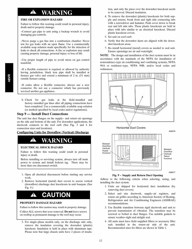
Step 9 — Install Duct ConnectionsThe unit has duct flanges on the supply-- and return--air openingson the side and bottom of the unit. For downshot applications, theductwork connects to the roof curb (See Fig. 3 and 4 forconnection sizes and locations).
Configuring Units for Downflow (Vertical) Discharge
ELECTRICAL SHOCK HAZARD
Failure to follow this warning could result in personalinjury or death.
Before installing or servicing system, always turn off mainpower to system and install lockout tag. There may bemore than one disconnect switch.
! WARNING
1. Open all electrical disconnects before starting any servicework.
2. Remove horizontal (metal) duct covers to access vertical(downflow) discharge duct knockouts in unit basepan. (SeeFig. 9.)
PROPERTY DAMAGE HAZARD
Failure to follow this caution may result in property damage.
Collect ALL screws that were removed.Do not leave screwson rooftop as permanent damage to the roof may occur.
CAUTION!
3. For single--phase models only, on the discharge side only,remove the insulation covering the downshot (plastic)knockout. Insulation is held in place with aluminum tape.Please note that large chassis units have 2 pieces of insula-
tion, and only the piece over the downshot knockout needsto be removed. Discard insulation.
4. To remove the downshot (plastic) knockouts for both sup-ply and returns, break front and right side connecting tabswith a screwdriver and hammer. Push cover down to breakrear and left side tabs. These plastic knockouts are held inplace with tabs similar to an electrical knockout. Discardplastic knockout covers.
5. Set unit on roof curb.
6. Verify that the downshot ducts are aligned with the down-shot knockout areas.
7. Re--install horizontal (metal) covers as needed to seal unit.Ensure opensings are air and watertight.
NOTE: The design and installation of the duct system must be inaccordance with the standards of the NFPA for installation ofnonresidence--type air conditioning and ventilating systems, NFPA90A or residence--type, NFPA 90B; and/or local codes andordinances.
Horizontal Duct CoversA09076
BasepanDownflow(Vertical)SupplyKnockout
BasepanDownflow (Vertical)ReturnKnockout
A09077
Fig. 9 -- Supply and Return Duct OpeningAdhere to the following criteria when selecting, sizing, andinstalling the duct system:
1. Units are shipped for horizontal duct installation (byremoving duct covers).
2. Select and size ductwork, supply--air registers, andreturn--air grilles according to American Society of Heating,Refrigeration and Air Conditioning Engineers (ASHRAE)recommendations.
3. Use flexible transition between rigid ductwork and unit toprevent transmission of vibration. The transition may bescrewed or bolted to duct flanges. Use suitable gaskets toensure weather--tight and airtight seal.
4. All units must have field--supplied filters or accessory filterrack installed in the return--air side of the unit.Recommended sizes for filters are shown in Table 1.
48VR
13
5. Size all ductwork for maximum required airflow (eitherheating or cooling) for unit being installed. Avoid abruptduct size increases or decreases or performance may beaffected.
6. Adequately insulate and weatherproof all ductwork locatedoutdoors. Insulate ducts passing through unconditionedspace, and use vapor barrier in accordance with latest issueof Sheet Metal and Air Conditioning Contractors NationalAssociation (SMACNA) and Air Conditioning Contractorsof America (ACCA) minimum installation standards forheating and air conditioning systems. Secure all ducts tobuilding structure.
7. Flash, weatherproof, and vibration isolate all openings inbuilding structure in accordance with local codes and goodbuilding practices.
Step 10 — Install Electrical Connections
ELECTRICAL SHOCK HAZARD
Failure to follow this warning could result in personalinjury or death.
The unit cabinet must have an uninterrupted, unbrokenelectrical ground. This ground may consist of an electricalwire connected to the unit ground screw in the controlcompartment, or conduit approved for electrical groundwhen installed in accordance with NFPA 70 (NEC) (latestedition) (in Canada, Canadian Electrical Code CSA C22.1)and local electrical codes.
! WARNING
UNIT COMPONENT DAMAGE HAZARD
Failure to follow this caution may result in damage to theunit being installed.
1. Make all electrical connections in accordance with NFPA70 (NEC) (latest edition) and local electrical codesgoverning such wiring. In Canada, all electricalconnections must be in accordance with CSA standardC22.1 Canadian Electrical Code Part 1 and applicablelocal codes. Refer to unit wiring diagram.
2. Use only copper conductor for connections betweenfield--supplied electrical disconnect switch and unit. DONOT USE ALUMINUM WIRE.
3. Be sure that high--voltage power to unit is withinoperating voltage range indicated on unit rating plate. On3--phase units, ensure phases are balanced within 2percent. Consult local power company for correction ofimproper voltage and/or phase imbalance.
4. Insulate low--voltage wires for highest voltage containedwithin conduit when low--voltage control wires are insame conduit as high--voltage wires.
5. Do not damage internal components when drillingthrough any panel to mount electrical hardware, conduit,etc.
! CAUTION
High--Voltage ConnectionsWhen routing power leads into unit, use only copper wire betweendisconnect and unit. The high voltage leads should be in a conduituntil they enter the duct panel; conduit termination at the ductpanel must be watertight.
The unit must have a separate electrical service with afield--supplied, waterproof disconnect switch mounted at, or withinsight from, the unit. Refer to the unit rating plate, NEC and local
codes for maximum fuse/circuit breaker size and minimum circuitamps (ampacity) for wire sizing.
The field--supplied disconnect switch box may be mounted on theunit over the high--voltage inlet hole when the standard power andlow--voltage entry points are used (See Fig. 3 and 4 for acceptablelocation).
NOTE: Field supplied disconnect switch box should bepositioned so that it does not cover up any of the unit gascombustion supply air louvers.
See unit wiring label (Fig. 14, 15 and 16) and Fig. 10 for referencewhen making high voltage connections. Proceed as follows tocomplete the high--voltage connections to the unit.
Single phase units:
1. Run the high--voltage (L1, L2) and ground lead into thecontrol box.
2. Connect ground lead to chassis ground connection.3. Locate the black and yellow wires connected to the line sideof the contactor (if equipped).
4. Connect field L1 to black wire from connection 11 of thecompressor contactor.
5. Connect field wire L2 to yellow wire from connection 23 ofthe compressor contactor.
Three--phase units:1. Run the high--voltage (L1, L2, L3) and ground lead into thecontrol box.
2. Connect ground lead to chassis ground connection.3. Locate the black and yellow wires connected to the line sideof the contactor (if equipped).
4. Connect field L1 to black wire from connection 11 of thecompressor contactor.
5. Connect field wire L3 to yellow wire from connection 13 ofthe compressor contactor.
6. Connect field wire L2 to blue wire from compressor.
Special Procedures for 208--v Operation
ELECTRICAL SHOCK HAZARD
Failure to follow this warning could result in personalinjury or death.
Make sure the power supply to the unit is switched OFF andinstall lockout tag. before making any wiring changes. Withdisconnect switch open, move black wire from transformer(3/16 in. [4.8 mm]) terminal marked 230 to terminal marked208. This retaps transformer to primary voltage of 208 vac.
! WARNING
ELECTRICAL SHOCK FIRE/EXPLOSION HAZARD
Failure to follow this warning could result in personalinjury or death and property damage.
Before making any wiring changes, make sure the gassupply is switched off first. Then switch off the powersupply to the unit and install lockout tag.
! WARNING
Control Voltage ConnectionsDo not use any type of power--stealing thermostat. Unit controlproblems may result.
Use no. 18 American Wire Gage (AWG) color--coded, insulated(35_C minimum) wires to make the control voltage connectionsbetween the thermostat and the unit. If the thermostat is locatedmore than 100 ft (30.5 m) from the unit (as measured along thecontrol voltage wires), use no. 16 AWG color--coded, insulated(35_C minimum) wires.
48VR
14
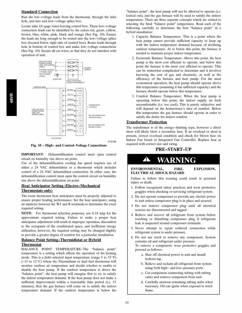
Standard ConnectionRun the low--voltage leads from the thermostat, through the inlethole, and into unit low--voltage splice box.
Locate nine 18--gage wires leaving control box. These low--voltageconnection leads can be identified by the colors red, green, yellow,brown, blue, white, pink, black and orange (See Fig. 10). Ensurethe leads are long enough to be routed into the low--voltage splicebox (located below right side of control box). Route leads throughhole in bottom of control box and make low--voltage connections(See Fig. 10). Secure all cut wires, so that they do not interfere withoperation of unit.
POWERSUPPLY
FIELD-SUPPLIEDFUSED DISCONNECT
HIGH VOLTAGEPOWER LEADS(SEE UNIT WIRINGLABEL)
EQUIP GR
3-PHASE SHOWN1-PHASE USES TWO POWER LEADS
SPLICE BOX
LOW-VOLTAGEPOWER LEADS(SEE UNITWIRING LABEL)
WHT(W1)W/W1
YEL (Y)Y1/Y
GGRN(G)
RED(R)
BRN(C)
BLU(DH)
R
C
DH
Y2
W2
PINK(Y2)
BLK(W2)
CONTROL BOX
(W2 ON 208/230 VAC MODELS ONLY)
THERMOSTAT(TYPICAL)
(DH ON 208/230 VAC MODELS ONLY)
OORN(O)
A13152
Fig. 10 -- High-- and Control--Voltage Connections
IMPORTANT: Dehumidification control must open controlcircuit on humidity rise above set point.Use of the dehumidification cooling fan speed requires use ofeither a 24 VAC dehumidistat or a thermostat which includescontrol of a 24 VAC dehumidistat connection. In either case, thedehumidification control must open the control circuit on humidityrise above the dehumidification set point.
Heat Anticipator Setting (Electro--MechanicalThermostats only)The room thermostat heat anticipator must be properly adjusted toensure proper heating performance. Set the heat anticipator, usingan ammeter between the W1 and R terminals to determine the exactrequired setting.
NOTE: For thermostat selection purposes, use 0.18 amp for theapproximate required setting. Failure to make a proper heatanticipator adjustment will result in improper operation, discomfortto the occupants of the conditioned space, and inefficient energyutilization; however, the required setting may be changed slightlyto provide a greater degree of comfort for a particular installation.
Balance Point Setting--Thermidistat or HybridThermostatBALANCE POINT TEMPERATURE--The “balance point”temperature is a setting which affects the operation of the heatingmode. This is a field--selected input temperature (range 5 to 55_F)(--15 to 12_C) where the Thermidistat or dual fuel thermostat willmonitor outdoor air temperature and decide whether to enable ordisable the heat pump. If the outdoor temperature is above the“balance point”, the heat pump will energize first to try to satisfythe indoor temperature demand. If the heat pump does not make asufficient improvement within a reasonable time period (i.e. 15minutes), then the gas furnace will come on to satisfy the indoortemperature demand. If the outdoor temperature is below the
“balance point”, the heat pump will not be allowed to operate (i.e.locked out), and the gas furnace will be used to satisfy the indoortemperature. There are three separate concepts which are related toselecting the final “balance point” temperature. Read each of thefollowing carefully to determine the best “balance point” in ahybrid installation:
1. Capacity Balance Temperature: This is a point where theheat pump cannot provide sufficient capacity to keep upwith the indoor temperature demand because of decliningoutdoor temperature. At or below this point, the furnace isneeded to maintain proper indoor temperature.
2. Economic Balance Temperature: Above this point, the heatpump is the most cost efficient to operate, and below thispoint the furnace is the most cost efficient to operate. Thiscan be somewhat complicated to determine and it involvesknowing the cost of gas and electricity, as well as theefficiency of the furnace and heat pump. For the mosteconomical operation, the heat pump should operate abovethis temperature (assuming it has sufficient capacity) and thefurnace should operate below this temperature.
3. Comfort Balance Temperature: When the heat pump isoperating below this point, the indoor supply air feelsuncomfortable (i.e. too cool). This is purely subjective andwill depend on the homeowner’s idea of comfort. Belowthis temperature the gas furnace should operate in order tosatisfy the desire for indoor comfort.
Transformer ProtectionThe transformer is of the energy--limiting type, however a directshort will likely blow a secondary fuse. If an overload or short ispresent, correct overload condition and check for blown fuse onIndoor Fan board or Integrated Gas Controller. Replace fuse asrequired with correct size and rating.
PRE--START--UP
ENVIRONMENTAL, FIRE, EXPLOSION,ELECTRICAL SHOCK HAZARD
Failure to follow this warning could result in personalinjury or death.
1. Follow recognized safety practices and wear protectivegoggles when checking or servicing refrigerant system.
2. Do not operate compressor or provide any electric powerto unit unless compressor plug is in place and secured.
3. Do not remove compressor plug until all electricalsources are disconnected and tagged.
4. Relieve and recover all refrigerant from system beforetouching or disturbing compressor plug if refrigerantleak is suspected around compressor terminals.
5. Never attempt to repair soldered connection whilerefrigerant system is under pressure.
6. Do not use torch to remove any component. Systemcontains oil and refrigerant under pressure.To remove a component, wear protective goggles andproceed as follows:
a. Shut off electrical power to unit and installlockout tag.
b. Relieve and reclaim all refrigerant from systemusing both high-- and low--pressure ports.
c. Cut component connecting tubing with tubingcutter and remove component from unit.
d. Carefully unsweat remaining tubing stubs whennecessary. Oil can ignite when exposed to torchflame.
! WARNING
48VR
15
Use the Start--Up Checklist supplied at the end of this book andproceed as follows to inspect and prepare the unit for initialstart--up:
1. Remove access panels (see Fig. 19).
2. Read and follow instructions on all DANGER, WARNING,CAUTION, and INFORMATION labels attached to, orshipped with unit.
3. Make the following inspections:
a. Inspect for shipping and handling damage, such asbroken lines, loose parts, disconnected wires, etc.
b. Inspect all field-- and factory--wiring connections. Besure that connections are completed and tight.
c. Ensure wires do not touch refrigerant tubing or sharpsheet metal edges.
d. Inspect coil fins. If damaged during shipping andhandling, carefully straighten fins with a fin comb.
FIRE, EXPLOSION HAZARD
Failure to follow this warning could result in personalinjury, death or property damage.
Do not purge gas supply into the combustion chamber. Donot use a match or other open flame to check for gas leaks.Use a commercially available soap solution madespecifically for the detection of leaks to check allconnections. A fire or explosion may result causingproperty damage, personal injury or loss of life.
! WARNING
4. Verify the following conditions:
a. Make sure gas line is free of air. Before lighting the unitfor the first time, perform the following with the gasvalve in the OFF position:
NOTE: If the gas supply pipe was not purged before connectingthe unit, it will be full of air. It is recommended that the groundjoint union be loosened, and the supply line be allowed to purgeuntil the odor of gas is detected. Never purge gas lines into acombustion chamber. Immediately upon detection of gas odor,retighten the union. Allow 5 minutes to elapse, then light unit.
b. Make sure that outdoor--fan blade is correctly positionedin the fan orifice.
c. Make sure that air filter(s) is in place.
d. Make sure that condensate drain trap is filled with waterto ensure proper drainage.
e. Make sure that all tools and miscellaneous loose partshave been removed.
START--UPStep 1 — Check for Refrigerant LeaksProceed as follows to locate and repair a refrigerant leak and tocharge the unit:
EXPLOSION HAZARD
Failure to follow this warning couldresult in death, serious personal injury,and/or property damage.
Never use air or gases containingoxygen for leak testing or operatingrefrigerant compressors. Pressurizedmixtures of air or gases containingoxygen can lead to an explosion.
! WARNING
1. Locate leak and make sure that refrigerant system pressurehas been relieved and reclaimed from both high-- andlow--pressure ports.
2. Repair leak following accepted practices.
NOTE: Install a filter drier whenever the system has been openedfor repair.
3. Add a small charge of Puron (R--410A) refrigerant vapor tosystem and leak--test unit.
4. Recover refrigerant from refrigerant system and evacuate to500 microns if no additional leaks are found.
5. Charge unit with Puron (R--410A) refrigerant, using anaccurate scale. Refer to unit rating plate for required charge.
Step 2 — Start--up Gas Heating and MakeAdjustmentsComplete the required procedures given in the Pre--Start--Upsection before starting the unit. Do not jumper any safety deviceswhen operating the unit. Make sure that burner orifices areproperly aligned. Unstable operation my occur when the burnerorifices in the manifold are misaligned.
Follow the lighting instructions on the heating section operationlabel (located on the inside of the control access panel) to start theheating section.
NOTE: Make sure that gas supply has been purged, and that allgas piping has been checked for leaks.
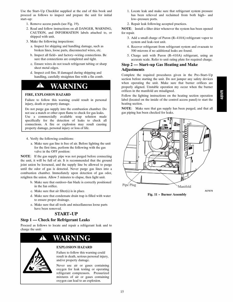
Pipe PlugManifold
A07679
Fig. 11 -- Burner Assembly
48VR
16
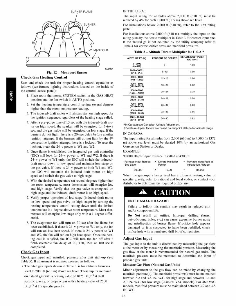
MANIFOLD
BURNER
BURNER FLAME
C99021
Fig. 12 -- Monoport BurnerCheck Gas Heating ControlStart and check the unit for proper heating control operation asfollows (see furnace lighting instructions located on the inside ofthe control access panel):
1. Place room thermostat SYSTEM switch in the GAS HEATposition and the fan switch in AUTO position.
2. Set the heating temperature control setting several degreeshigher than the room temperature reading.
3. The induced--draft motor will always start on high speed forthe ignition sequence, regardless of the heating stage called.
4. After a pre--purge time of 15 sec with the induced--draft mo-tor on high speed, the sparker will be energized for 3--to--8sec, and the gas valve will be energized on low stage. If theburners do not light, there is a 20--sec delay before anotherignition attempt. If the burners still do not light by the 4th
consecutive ignition attempt, there is a lockout. To reset thelockout, break the 24--v power to W1 and W2.
5. Once flame is established the integrated gas unit controller(IGC) will look for 24--v power to W1 and W2. If there is24--v power to W1 only, the IGC will switch the induced--draft motor down to low speed and maintain low stage onthe gas valve. If there is 24--v power to both W1 and W2,the IGC will maintain the induced--draft motor on highspeed and switch the gas valve to high stage.
6. With the desired temperature set several degrees higher thanthe room temperature, most thermostats will energize lowand high stage. Verify that the gas valve is energized onhigh stage and the induced--draft motor is on high speed.
7. Verify proper operation of low stage (induced--draft motoron low speed and gas valve on high stage) by turning theheating temperature control setting down until the desiredtemperature is 1 degree above room temperature. Most ther-mostats will energize low stage only with a 1 degree differ-ential.
8. The evaporator fan will turn on 30 sec after the flame hasbeen established. If there is 24--v power to W1 only, the fanwill run on low heat speed. If there is 24--v power to W1and W2, the fan will run on high heat speed. Once the heat-ing coll is satisfied, the IGC will turn the fan off after afield--selectable fan delay of 90, 120, 150, or 180 sec iscompleted.
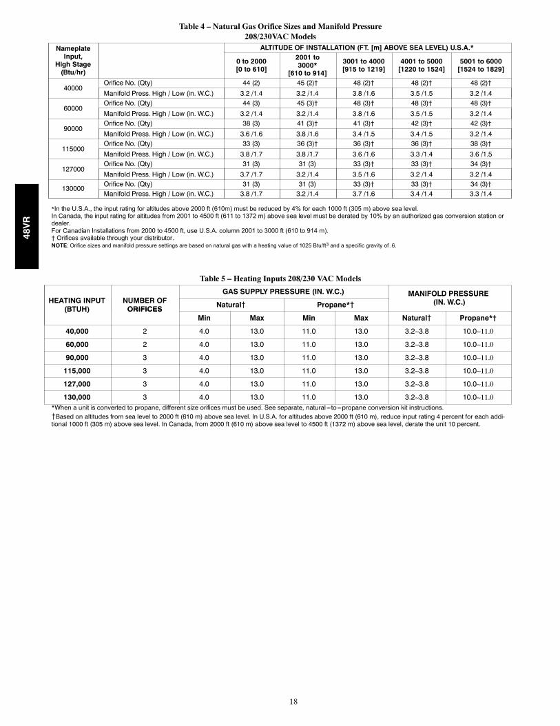
Check Gas InputCheck gas input and manifold pressure after unit start--up (SeeTable 5). If adjustment is required proceed as follows:
S The rated gas inputs shown in Table 5 is for altitudes from sea
level to 2000 ft (610 m) above sea level. These inputs are based
on natural gas with a heating value of 1025 Btu/ft3 at 0.60
specific gravity, or propane gas with a heating value of 2500
Btu/ft3 at 1.5 specific gravity.
IN THE U.S.A.:
The input rating for altitudes above 2,000 ft (610 m) must bereduced by 4% for each 1,000 ft (305 m) above see level.
For installations below 2,000 ft (610 m), refer to the unit ratingplate.
For installations above 2,000 ft (610 m). multiply the input on therating plate by the derate multiplier in Table 3 for correct input rate.If the natural gs is not de--rated by the utility company refer toTable 4 for correct orifice sizes and manifold pressures.
Table 3 – Altitude Derate Multiplier for U.S.A.*
ALTITUDE FT (M) PERCENT OF DERATE DERATE MULTIPLIERFACTOR{
0---2000(0---610) 0 1.00
2001---3000*(610---914) 8---12 0.90
3001---4000(915---1219) 12---16 0.86
4001---5000(1220---1524) 16---20 0.82
5001---6000(1524 ---1829) 20---24 0.78
6001---7000(1829---2134) 24---28 0.74
7001---8000(2134---2438) 28---32 0.70
8001---9000(2439---2743) 32---36 0.66
9001---10,000(2744---3048) 36---40 0.62
*In Canada see Canadian Altitude Adjustment.{Derate multiplier factors are based on midpoint altitude for altitude range.
IN CANADA:
The input rating for altitudes from 2,000 (610 m) to 4,500 ft (1372m) above sea level must be derated 10% by an authorized GasConversion Station or Dealer.
EXAMPLE:
90,000 Btu/hr Input Furnace Installed at 4300 ft.
Furnace Input Rate atSea Level
X Derate MultiplierFactor
= Furnace Input Rate atInstallation Altitude
90,000 X 0.90 = 81,000
When the gas supply being used has a different heating value orspecific gravity, refer to national and local codes, or contact yourdistributor to determine the required orifice size.
UNIT DAMAGE HAZARD
Failure to follow this caution may result in reduced unitand/or component life.
Do Not redrill an orifice. Improper drilling (burrs,out--of--round holes, etc.) can cause excessive burner noiseand misdirection of burner flame. If orifice hole appearsdamaged or it is suspected to have been redrilled, checkorifice hole with a numbered drill bit of correct size.
! CAUTION
Adjust Gas InputThe gas input to the unit is determined by measuring the gas flowat the meter or by measuring the manifold pressure. Measuring thegas flow at the meter is recommended for natural gas units. Themanifold pressure must be measured to determine the input ofpropane gas units.
Measure Gas Flow (Natural Gas Units)
Minor adjustment to the gas flow can be made by changing themanifold pressure(s). The manifold pressure(s) must be maintainedbetween 3.2 and 3.8 IN. W.C. for high stage and between 1.4 and2.0 IN. W.C. for low stage (208/230 VAC models). For 460 VACmodels, manifold pressure must be maintained between 3.2 and 3.8IN. W.C.
48VR
17
REGULATOR COVER SCREW
PLASTIC ADJUST SCREW
LOW STAGE GAS PRESSURE REGULATOR ADJUSTMENT
MANIFOLDPRESSURE TAP
INLETPRESSURE TAP
ON/OFF SWITCH
REGULATOR SPRING
HIGH STAGE GAS PRESSURE REGULATOR ADJUSTMENT
1/2˝ NPT OUTLET
1/2˝ NPT INLET
A04167
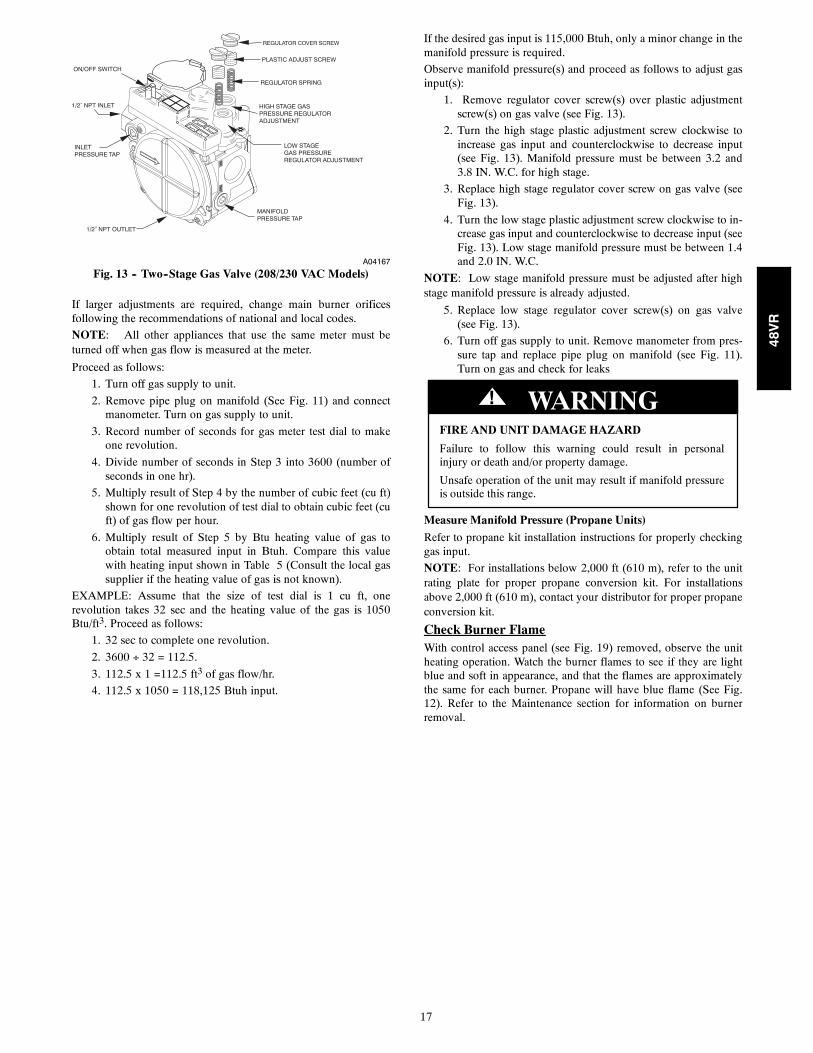
Fig. 13 -- Two--Stage Gas Valve (208/230 VAC Models)
If larger adjustments are required, change main burner orificesfollowing the recommendations of national and local codes.
NOTE: All other appliances that use the same meter must beturned off when gas flow is measured at the meter.
Proceed as follows:
1. Turn off gas supply to unit.
2. Remove pipe plug on manifold (See Fig. 11) and connectmanometer. Turn on gas supply to unit.
3. Record number of seconds for gas meter test dial to makeone revolution.
4. Divide number of seconds in Step 3 into 3600 (number ofseconds in one hr).
5. Multiply result of Step 4 by the number of cubic feet (cu ft)shown for one revolution of test dial to obtain cubic feet (cuft) of gas flow per hour.
6. Multiply result of Step 5 by Btu heating value of gas toobtain total measured input in Btuh. Compare this valuewith heating input shown in Table 5 (Consult the local gassupplier if the heating value of gas is not known).
EXAMPLE: Assume that the size of test dial is 1 cu ft, onerevolution takes 32 sec and the heating value of the gas is 1050Btu/ft3. Proceed as follows:
1. 32 sec to complete one revolution.
2. 3600 32 = 112.5.
3. 112.5 x 1 =112.5 ft3 of gas flow/hr.
4. 112.5 x 1050 = 118,125 Btuh input.
If the desired gas input is 115,000 Btuh, only a minor change in themanifold pressure is required.
Observe manifold pressure(s) and proceed as follows to adjust gasinput(s):
1. Remove regulator cover screw(s) over plastic adjustmentscrew(s) on gas valve (see Fig. 13).
2. Turn the high stage plastic adjustment screw clockwise toincrease gas input and counterclockwise to decrease input(see Fig. 13). Manifold pressure must be between 3.2 and3.8 IN. W.C. for high stage.
3. Replace high stage regulator cover screw on gas valve (seeFig. 13).
4. Turn the low stage plastic adjustment screw clockwise to in-crease gas input and counterclockwise to decrease input (seeFig. 13). Low stage manifold pressure must be between 1.4and 2.0 IN. W.C.
NOTE: Low stage manifold pressure must be adjusted after highstage manifold pressure is already adjusted.
5. Replace low stage regulator cover screw(s) on gas valve(see Fig. 13).
6. Turn off gas supply to unit. Remove manometer from pres-sure tap and replace pipe plug on manifold (see Fig. 11).Turn on gas and check for leaks
FIRE AND UNIT DAMAGE HAZARD
Failure to follow this warning could result in personalinjury or death and/or property damage.
Unsafe operation of the unit may result if manifold pressureis outside this range.
! WARNING
Measure Manifold Pressure (Propane Units)
Refer to propane kit installation instructions for properly checkinggas input.
NOTE: For installations below 2,000 ft (610 m), refer to the unitrating plate for proper propane conversion kit. For installationsabove 2,000 ft (610 m), contact your distributor for proper propaneconversion kit.
Check Burner FlameWith control access panel (see Fig. 19) removed, observe the unitheating operation. Watch the burner flames to see if they are lightblue and soft in appearance, and that the flames are approximatelythe same for each burner. Propane will have blue flame (See Fig.12). Refer to the Maintenance section for information on burnerremoval.
48VR
18
Table 4 – Natural Gas Orifice Sizes and Manifold Pressure208/230VAC Models
NameplateInput,
High Stage(Btu/hr)
ALTITUDE OF INSTALLATION (FT. [m] ABOVE SEA LEVEL) U.S.A.*
0 to 2000[0 to 610]
2001 to3000*
[610 to 914]
3001 to 4000[915 to 1219]
4001 to 5000[1220 to 1524]
5001 to 6000[1524 to 1829]
40000Orifice No. (Qty) 44 (2) 45 (2)† 48 (2)† 48 (2)† 48 (2)†Manifold Press. High / Low (in. W.C.) 3.2 /1.4 3.2 /1.4 3.8 /1.6 3.5 /1.5 3.2 /1.4
60000Orifice No. (Qty) 44 (3) 45 (3)† 48 (3)† 48 (3)† 48 (3)†Manifold Press. High / Low (in. W.C.) 3.2 /1.4 3.2 /1.4 3.8 /1.6 3.5 /1.5 3.2 /1.4
90000Orifice No. (Qty) 38 (3) 41 (3)† 41 (3)† 42 (3)† 42 (3)†Manifold Press. High / Low (in. W.C.) 3.6 /1.6 3.8 /1.6 3.4 /1.5 3.4 /1.5 3.2 /1.4
115000Orifice No. (Qty) 33 (3) 36 (3)† 36 (3)† 36 (3)† 38 (3)†Manifold Press. High / Low (in. W.C.) 3.8 /1.7 3.8 /1.7 3.6 /1.6 3.3 /1.4 3.6 /1.5
127000Orifice No. (Qty) 31 (3) 31 (3) 33 (3)† 33 (3)† 34 (3)†Manifold Press. High / Low (in. W.C.) 3.7 /1.7 3.2 /1.4 3.5 /1.6 3.2 /1.4 3.2 /1.4
130000Orifice No. (Qty) 31 (3) 31 (3) 33 (3)† 33 (3)† 34 (3)†Manifold Press. High / Low (in. W.C.) 3.8 /1.7 3.2 /1.4 3.7 /1.6 3.4 /1.4 3.3 /1.4
*In the U.S.A., the input rating for altitudes above 2000 ft (610m) must be reduced by 4% for each 1000 ft (305 m) above sea level.In Canada, the input rating for altitudes from 2001 to 4500 ft (611 to 1372 m) above sea level must be derated by 10% by an authorized gas conversion station ordealer.For Canadian Installations from 2000 to 4500 ft, use U.S.A. column 2001 to 3000 ft (610 to 914 m).† Orifices available through your distributor.NOTE: Orifice sizes and manifold pressure settings are based on natural gas with a heating value of 1025 Btu/ft3 and a specific gravity of .6.
Table 5 – Heating Inputs 208/230 VAC Models
HEATING INPUT(BTUH)
NUMBER OFGAS SUPPLY PRESSURE (IN. W.C.) MANIFOLD PRESSURE
NUMBER OFORIFICES Natural{ Propane*{
MANIFOLD PRESSURE(IN. W.C.)
ORIFICESMin Max Min Max Natural{ Propane*†
40,000 2 4.0 13.0 11.0 13.0 3.23.8 10.0
60,000 2 4.0 13.0 11.0 13.0 3.23.8 10.0
90,000 3 4.0 13.0 11.0 13.0 3.23.8 10.0
115,000 3 4.0 13.0 11.0 13.0 3.23.8 10.0
127,000 3 4.0 13.0 11.0 13.0 3.23.8 10.0
130,000 3 4.0 13.0 11.0 13.0 3.23.8 10.0*When a unit is converted to propane, different size orifices must be used. See separate, natural ---to---propane conversion kit instructions.{Based on altitudes from sea level to 2000 ft (610 m) above sea level. In U.S.A. for altitudes above 2000 ft (610 m), reduce input rating 4 percent for each addi-tional 1000 ft (305 m) above sea level. In Canada, from 2000 ft (610 m) above sea level to 4500 ft (1372 m) above sea level, derate the unit 10 percent.
48VR
19
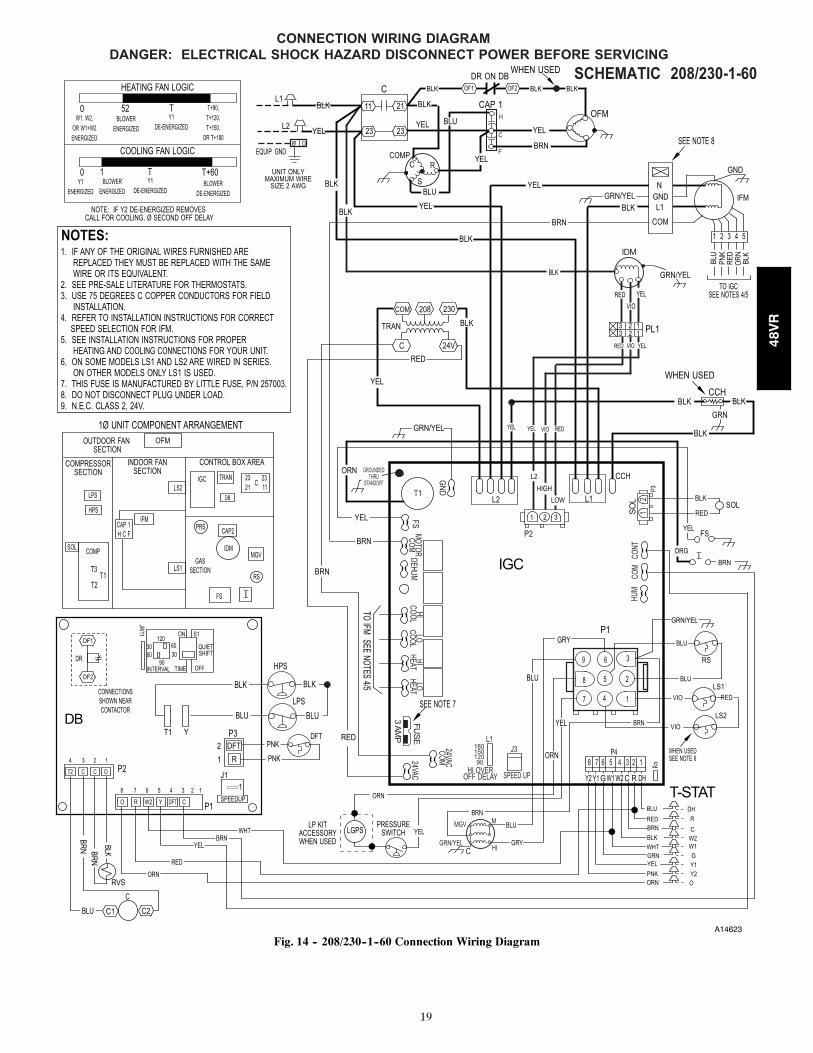
A14623
Fig. 14 -- 208/230--1--60 Connection Wiring Diagram
48VR
20
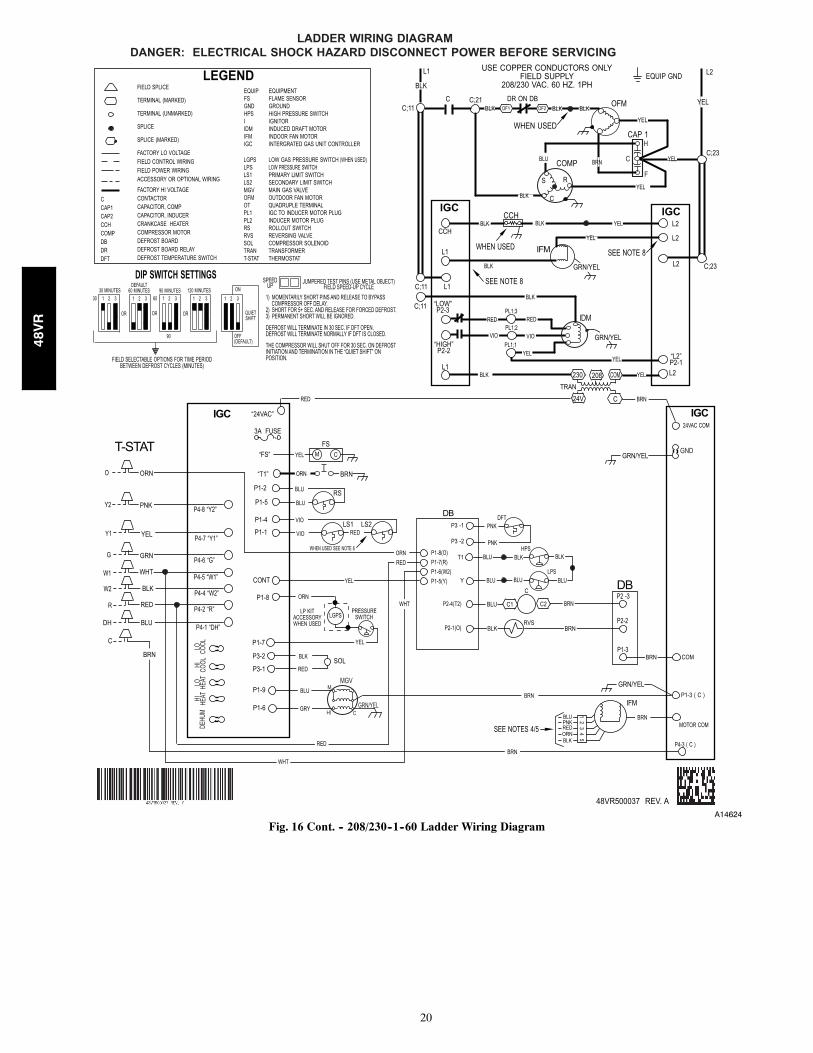
A14624
Fig. 16 Cont. -- 208/230--1--60 Ladder Wiring Diagram
48VR
21
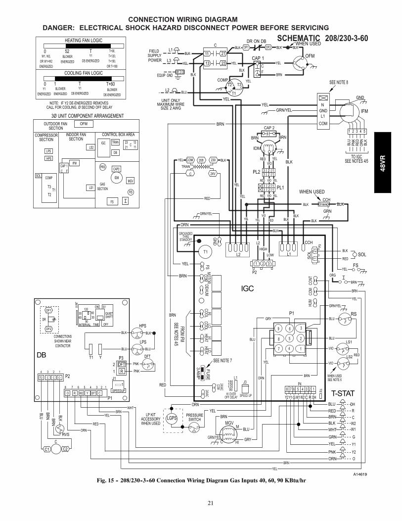
A14619
Fig. 15 -- 208/230--3--60 Connection Wiring Diagram Gas Inputs 40, 60, 90 KBtu/hr
48VR
22
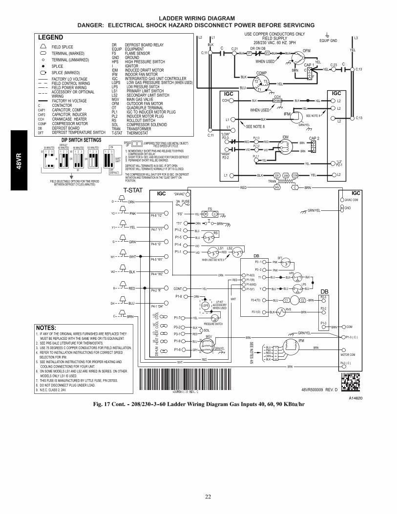
A14620
Fig. 17 Cont. -- 208/230--3--60 Ladder Wiring Diagram Gas Inputs 40, 60, 90 KBtu/hr
48VR
23
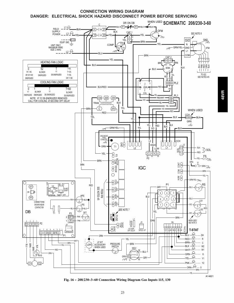
A14621
Fig. 16 -- 208/230--3--60 Connection Wiring Diagram Gas Inputs 115, 130
48VR
24
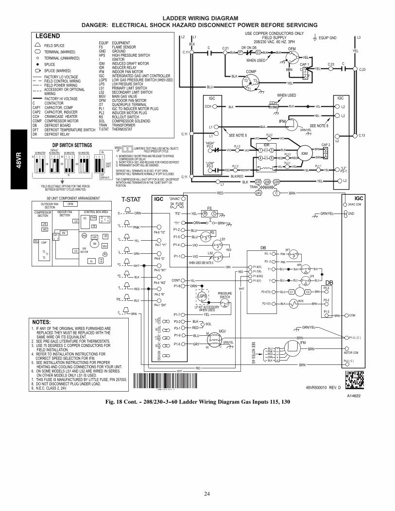
A14622
Fig. 18 Cont. -- 208/230--3--60 Ladder Wiring Diagram Gas Inputs 115, 130
48VR
25
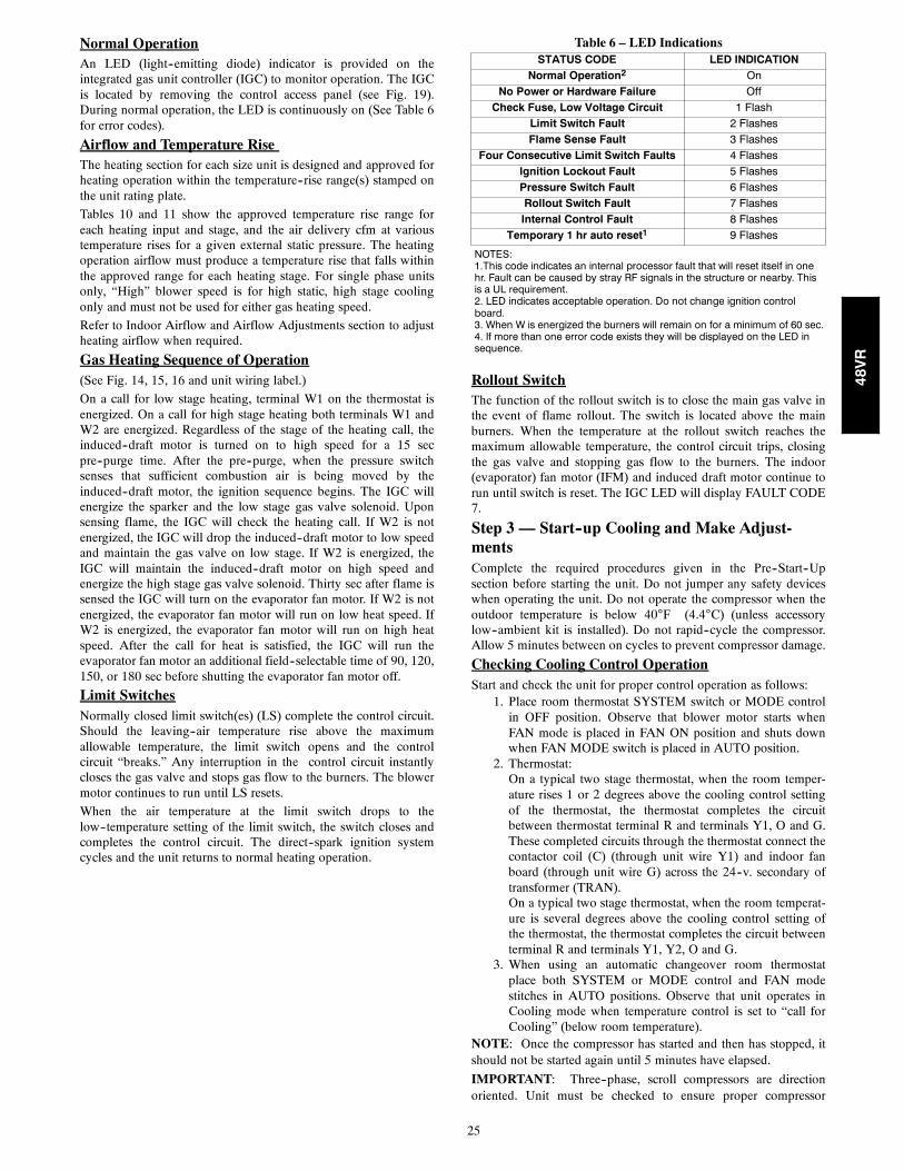
Normal OperationAn LED (light--emitting diode) indicator is provided on theintegrated gas unit controller (IGC) to monitor operation. The IGCis located by removing the control access panel (see Fig. 19).During normal operation, the LED is continuously on (See Table 6for error codes).
Airflow and Temperature RiseThe heating section for each size unit is designed and approved forheating operation within the temperature--rise range(s) stamped onthe unit rating plate.
Tables 10 and 11 show the approved temperature rise range foreach heating input and stage, and the air delivery cfm at varioustemperature rises for a given external static pressure. The heatingoperation airflow must produce a temperature rise that falls withinthe approved range for each heating stage. For single phase unitsonly, “High” blower speed is for high static, high stage coolingonly and must not be used for either gas heating speed.
Refer to Indoor Airflow and Airflow Adjustments section to adjustheating airflow when required.
Gas Heating Sequence of Operation(See Fig. 14, 15, 16 and unit wiring label.)
On a call for low stage heating, terminal W1 on the thermostat isenergized. On a call for high stage heating both terminals W1 andW2 are energized. Regardless of the stage of the heating call, theinduced--draft motor is turned on to high speed for a 15 secpre--purge time. After the pre--purge, when the pressure switchsenses that sufficient combustion air is being moved by theinduced--draft motor, the ignition sequence begins. The IGC willenergize the sparker and the low stage gas valve solenoid. Uponsensing flame, the IGC will check the heating call. If W2 is notenergized, the IGC will drop the induced--draft motor to low speedand maintain the gas valve on low stage. If W2 is energized, theIGC will maintain the induced--draft motor on high speed andenergize the high stage gas valve solenoid. Thirty sec after flame issensed the IGC will turn on the evaporator fan motor. If W2 is notenergized, the evaporator fan motor will run on low heat speed. IfW2 is energized, the evaporator fan motor will run on high heatspeed. After the call for heat is satisfied, the IGC will run theevaporator fan motor an additional field--selectable time of 90, 120,150, or 180 sec before shutting the evaporator fan motor off.
Limit SwitchesNormally closed limit switch(es) (LS) complete the control circuit.Should the leaving--air temperature rise above the maximumallowable temperature, the limit switch opens and the controlcircuit “breaks.” Any interruption in the control circuit instantlycloses the gas valve and stops gas flow to the burners. The blowermotor continues to run until LS resets.
When the air temperature at the limit switch drops to thelow--temperature setting of the limit switch, the switch closes andcompletes the control circuit. The direct--spark ignition systemcycles and the unit returns to normal heating operation.
Table 6 – LED IndicationsSTATUS CODE LED INDICATION
Normal Operation2 On
No Power or Hardware Failure Off
Check Fuse, Low Voltage Circuit 1 Flash
Limit Switch Fault 2 Flashes
Flame Sense Fault 3 Flashes
Four Consecutive Limit Switch Faults 4 Flashes
Ignition Lockout Fault 5 Flashes
Pressure Switch Fault 6 Flashes
Rollout Switch Fault 7 Flashes
Internal Control Fault 8 Flashes
Temporary 1 hr auto reset1 9 Flashes
NOTES:1.This code indicates an internal processor fault that will reset itself in onehr. Fault can be caused by stray RF signals in the structure or nearby. Thisis a UL requirement.2. LED indicates acceptable operation. Do not change ignition controlboard.3. When W is energized the burners will remain on for a minimum of 60 sec.4. If more than one error code exists they will be displayed on the LED insequence.
Rollout SwitchThe function of the rollout switch is to close the main gas valve inthe event of flame rollout. The switch is located above the mainburners. When the temperature at the rollout switch reaches themaximum allowable temperature, the control circuit trips, closingthe gas valve and stopping gas flow to the burners. The indoor(evaporator) fan motor (IFM) and induced draft motor continue torun until switch is reset. The IGC LED will display FAULT CODE7.
Step 3 — Start--up Cooling and Make Adjust-mentsComplete the required procedures given in the Pre--Start--Upsection before starting the unit. Do not jumper any safety deviceswhen operating the unit. Do not operate the compressor when theoutdoor temperature is below 40F (4.4C) (unless accessorylow--ambient kit is installed). Do not rapid--cycle the compressor.Allow 5 minutes between on cycles to prevent compressor damage.
Checking Cooling Control OperationStart and check the unit for proper control operation as follows:
1. Place room thermostat SYSTEM switch or MODE controlin OFF position. Observe that blower motor starts whenFAN mode is placed in FAN ON position and shuts downwhen FAN MODE switch is placed in AUTO position.
2. Thermostat:On a typical two stage thermostat, when the room temper-ature rises 1 or 2 degrees above the cooling control settingof the thermostat, the thermostat completes the circuitbetween thermostat terminal R and terminals Y1, O and G.These completed circuits through the thermostat connect thecontactor coil (C) (through unit wire Y1) and indoor fanboard (through unit wire G) across the 24--v. secondary oftransformer (TRAN).On a typical two stage thermostat, when the room temperat-ure is several degrees above the cooling control setting ofthe thermostat, the thermostat completes the circuit betweenterminal R and terminals Y1, Y2, O and G.
3. When using an automatic changeover room thermostatplace both SYSTEM or MODE control and FAN modestitches in AUTO positions. Observe that unit operates inCooling mode when temperature control is set to “call forCooling” (below room temperature).
NOTE: Once the compressor has started and then has stopped, itshould not be started again until 5 minutes have elapsed.
IMPORTANT: Three--phase, scroll compressors are directionoriented. Unit must be checked to ensure proper compressor
48VR
26
3--phase power lead orientation. If not corrected within 5 minutes,the internal protector will shut off the compressor. The 3--phasepower leads to the unit must be reversed to correct rotation. Whenturning backwards, the difference between compressor suction anddischarge pressures will be minimal.
Checking and Adjusting Refrigerant ChargeThe refrigerant system is fully charged with PuronR (R--410A)refrigerant and is tested and factory sealed. Allow system to operatea minimum of 15 minutes before checking or adjusting charge.
NOTE: Adjustment of the refrigerant charge is not required unlessthe unit is suspected of not having the proper PuronR (R--410A)charge.
A subcooling chart is attached to the inside of the compressoraccess panel. (See Table 9 and Fig. 19.) The chart includes therequired liquid line temperature at given discharge line pressuresand outdoor ambient temperatures for high stage cooling.
An accurate thermocouple-- or thermistor--type thermometer, and agauge manifold are required when using the subcooling chargingmethod for evaluating the unit charge. Do not use mercury or smalldial--type thermometers because they are not adequate for this typeof measurement.
UNIT DAMAGE HAZARD
Failure to follow this caution may result in unit damage.
When evaluating the refrigerant charge, an indicatedadjustment to the specified factory charge must always bevery minimal. If a substantial adjustment is indicated, anabnormal condition exists somewhere in the cooling system,such as insufficient airflow across either coil or both coils.
! CAUTION
IMPORTANT: When evaluating the refrigerant charge, anindicated adjustment to the specified factory charge must always bevery minimal. If a substantial adjustment is indicated, an abnormalcondition exists somewhere in the cooling system, such asinsufficient airflow across either coil or both coils.
Proceed as follows:
1. Remove caps from low-- and high--pressure service fittings.
2. Using hoses with valve core depressors, attach low-- andhigh--pressure gauge hoses to low-- and high--pressureservice fittings, respectively.
3. Start unit in high stage cooling mode and let unit run untilsystem pressures stabilize.
4. Measure and record the following:
a. Outdoor ambient--air temperature (F [C] db).
b. Liquid line temperature (F [C]).
c. Discharge (high--side) pressure (psig).
d. Suction (low--side) pressure (psig) (for reference only).
5. Using “Subcooling Charging Charts,” compare outdoor--airtemperature(F [C] db) with the discharge line pressure(psig) to determine desired system operating liquid linetemperature (See Table 9).
6. Compare actual liquid line temperature with desired liquidline temperature. Using a tolerance of 2F (1.1C), addrefrigerant if actual temperature is more than 2F (1.1C)higher than proper liquid line temperature, or removerefrigerant if actual temperature is more than 2F (1.1C)lower than required liquid line temperature.
NOTE: If the problem causing the inaccurate readings is arefrigerant leak, refer to the Check for Refrigerant Leaks section.
Indoor Airflow and Airflow Adjustments
UNIT OPERATION HAZARD
Failure to follow this caution may result in unit damage.
For cooling operation, the recommended airflow is 350 to450 cfm for each 12,000 Btuh of rated cooling capacity. Forheating operation, the airflow must produce a temperaturerise that falls within the range stamped on the unit ratingplate.
CAUTION!
NOTE: Be sure that all supply--and return--air grilles are open,free from obstructions, and adjusted properly.
ELECTRICAL SHOCK HAZARD
Failure to follow this warning could result in personalinjury or death.
Disconnect electrical power to the unit and install lockouttag before changing blower speed(s).
! WARNING
This unit has independent fan speeds for low stage cooling andhigh stage cooling. In addition, units have the field--selectablecapability to run an enhanced dehumidification (’DHUM’) speedon high stage cooling (as low as 320CFM per ton). Coupled withthe improved dehumidification associated with low stage cooling,the DHUM speed allows for a complete dehumidification solutionindependent of cooling stage. Units also have independent fanspeeds for low stage gas heating and high stage gas heating. Table7 shows the operation modes and the associated fan speeds witheach mode:
Table 7 – Operation Modes and Fan Speeds208/230 VAC Models
OPERATION MODE FAN SPEED TAPCONNECTION
Low Stage Gas Heating LO HEAT
High Stage Gas Heating HI HEAT
Low Stage Cooling/Heat Pump LO COOL
High Stage Cooling/Heat Pump HI COOL
High Stage EnhancedDehumidification Cooling DHUM
Continuous Fan LO COOL
The evaporator fan motor is factory set to provide 5 different fanspeeds to choose from for the various operation modes. Models arefactory--shipped with 4 speed wires connected with one sparespeed wire available.
48VR
27
Table 8 – Color Coding for Indoor Fan Motor Leads
Black = High Speed
Orange = Med---High Speed
Red = Med Speed
Pink = Med---Low Speed
Blue = Low Speed
Selection of Proper Fan Speeds for OperationModes:NOTE: All models are factory--shipped for nominal high stageand low stage cooling airflow operation at minimum external staticpressure. Many models are factory--shipped for nominal high stageand/or low stage gas heating airflow at minimum external staticpressure. Table 10 and 11 provide airflow data for higher externalstatic pressures.
Low Stage Gas Heating: Table 10 and 11 show the suitability ofeach speed for a given external static pressure for low stage gasheating. Any speed/static combination that is outside the rise rangeis marked “NA” and must not be used. For single phase units only,”High” blower speed is for high static, high stage cooling only andmust not be used for low stage gas heating speed. The unit mustoperate within the low stage gas heat rise range printed on therating plate. Connect the chosen fan speed wire to “LO HEAT”connection on the IGC Board (see Fig. 17).
High Stage Gas Heating: Table 10 and 11 show the suitability ofeach speed for a given external static pressure for high stage gasheating. Any speed/static combination that is outside the rise rangeis marked “NA” and must not be used. For single phase units only,”High” blower speed is for high static, high stage cooling only andmust not be used for high stage gas heating speed. The unit mustoperate within the high stage gas heat rise range printed on therating plate. Connect the chosen fan speed wire to “HI HEAT”connection on the IGC Board (see Fig. 17).
Low Stage Cooling/Heat Pump: Using Tables 12, 13, and 14,and the nominal airflow for low stage cooling (Table 1) find theexternal static pressure drops for wet coil, economizer, and filter,and add them to dry coil measured on the system. Using this totalstatic pressure, use Table 10 or 11 to find the airflows available atthe total static pressure. Connect the chosen fan speed wire to “LOCOOL” connection on the IGC Board (see Fig. 17).
High Stage Cooling/Heat Pump:Using Tables 12, 13, and 14,find the external static pressure drops for wet coil, economizer, andfilter, and add them to dry coil measured on the system. Using thistotal static pressure, use Table 10 or 11 to find the airflowsavailable at the total static pressure. The speed chosen must provideairflow of between 350 to 450 CFM per ton of cooling. Connectthe chosen fan speed wire to “HI COOL” connection on the IGCBoard (See Fig. 17).
High Stage Enhanced Dehumidification Cooling: Using thetotal static pressure for selecting the high stage cooling speed, useTable 10 or 11 to find lower speed/airflows available at that totalstatic pressure. All airflows highlighted in Table 10 and 11 areacceptable for Dehum speed. The speed chosen must provideairflow of between 320 to 400 CFM per ton of cooling. Connectthe chosen fan speed wire to “DHUM” connection on the IGCBoard (see Fig. 17).
To activate the high stage enhanced dehumidification coolingmode, the shunt jumper in Fig. 17 must be moved from the No DHto DH selection (See Fig. 17, close up).
Continuous Fan (All models): Continuous fan speed is the samespeed as Low Stage Cooling.
Cooling Sequence of Operationa. Continuous Fan
(1.) Thermostat closes circuit R to G energizing theblower motor for continuous fan. The indoor fan isenergized on low speed.
b. Cooling Mode
(1.) Low Stage: Thermostat closes R to G, R to Y1and R to O. The compressor and indoor fan areenergized on low speed. The outdoor fan is alsoenergized.
(2.) High Stage: Thermostat closes R to G, R to Y1, Rto Y2 and R to O. The compressor and indoor fanare energized on high speed. The outdoor fan isalso energized.
c. Heat Pump Mode
(1.) Low Stage: Thermostat closes R to G, R to Y1.The compressor and indoor fan are energized onlow speed. The outdoor fan is also energized.
(2.) High Stage: Thermostat closes R to G, R to Y1, Rto Y2. The compressor and indoor fan are ener-gized on high speed. The outdoor fan is also ener-gized.
d. Defrost Mode
(1.) Outdoor Fan is disabled, thermostat closes R to Oand R to W1. Low stage gas heat tempers the leav-ing air. When defrost is complete, unit will returnto heating mode. If room thermostat is satisfiedduring defrost, unit will shut down and restart indefrost on next call for heat.
Step 4 — Defrost ControlQuiet ShiftQuiet Shift is a field--selectable defrost mode, which will eliminateoccasional noise that could be heard at the start of defrost cycle andrestarting of heating cycle. It is selected by placing DIP switch 3(on defrost board) in ON position.
When Quiet Shift switch is placed in ON position, and a defrost isinitiated, the following sequence of operation will occur. Reversingvalve will energize, outdoor fan will turn off, compressor will turnoff for 30 sec and then turn back on to complete defrost. At thestart of heating after conclusion of defrost reversing valve willde--energize, compressor will turn off for another 30 sec, and theoutdoor fan will stay off for 40 sec, before starting in the Heatingmode.
DefrostThe defrost control is a time/temperature control which includes afield--selectable time period (DIP switch 1 and 2 on the board)between defrost cycles of 30, 60, 90, or 120 minutes (factory set at60 minutes). To initiate a forced defrost, two options are availabledepending on the status of the defrost thermostat.
48VR
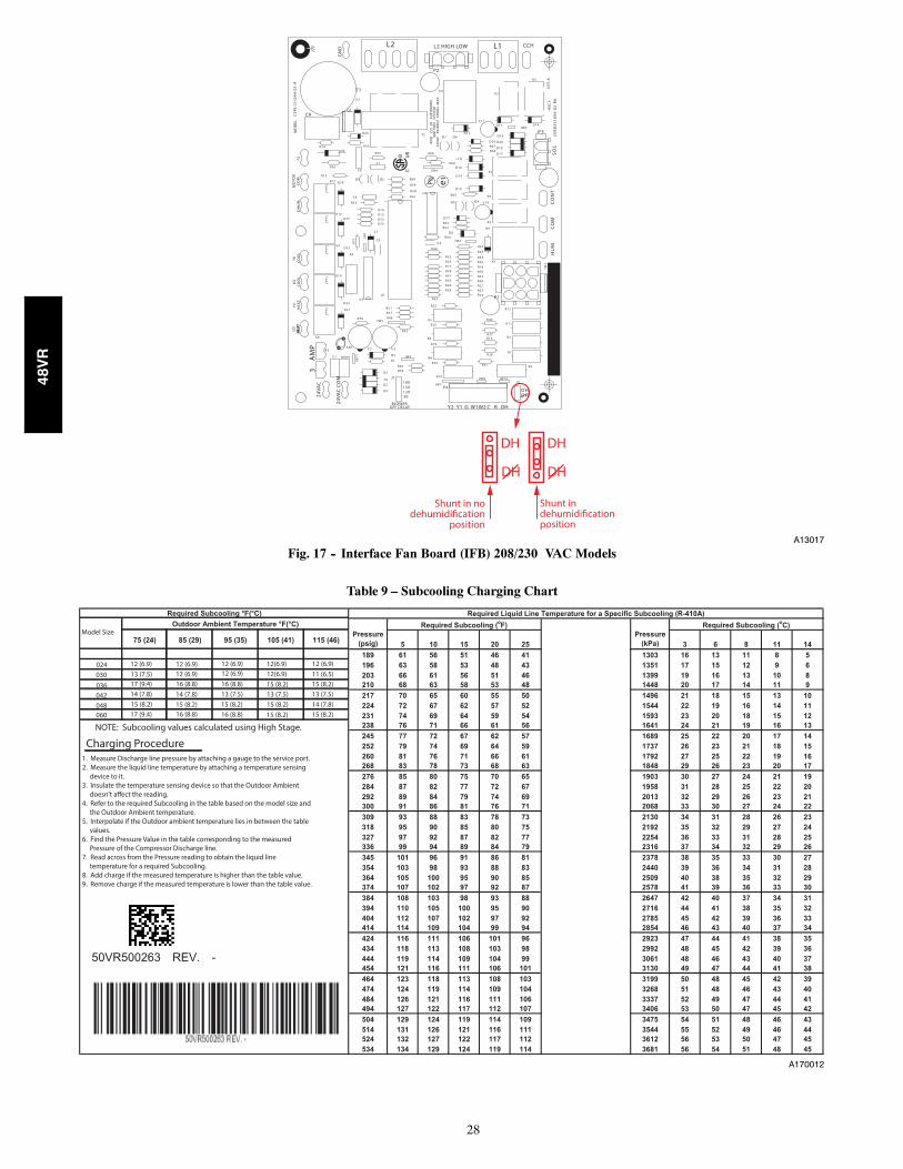
28
DH
DH
DH
DH
Shunt in nodehumidification
position
Shunt in dehumidificationposition
L2 L1L2 HIGH LOW CCH
P2
GN
D
MO
DEL
CEP
L13
10
94
-01
-R
T1
C9
CEB
D4
31
09
4-0
2-R
AH
SCI
SST-
A
SOL
P3
AN
SI
Z21
.20
AU
TOM
ATIC
IGN
ITIO
N
SYST
EM24
VAC
50
/60h
Z 3
50M
a M
AX
.
K3K4
T2
K5
C11
Q7 Q6D13
D12 D14JW6
D19
D28 D20R67 D18R66
D17R68
R69D16
D15K7
D11
D7
JW4
R57
C7
Q2
D26
Q3
R55R54D6
R56
R13
C8
Q1K11 D24R60
R59
FSH
ID
HU
MC
OO
LLO CO
OL
LO HEA
TH
EAT
HI
HEA
T
Pb e1
R58
R61C6
R53
K12R14R15
D25 R72R73
Z1
C5
K9D22
R2
U2D10
R65
Q4Q5
K6
C10
D27
R63R62
R64D8
JW3C4
R44
K2
D9
R43
R45
R33R30
R39R42R36R21R27
R18
R24
R32
R38R41R35R20
R17
R26
R29
R22
R22
K10
1
R7
1 JW1
MO
TOR
CO
MD23
D21
U3
U1
AM
P3
K8
J1
F1
P4
24VA
C
24VA
C C
OM
JW11
BLOWEROFF DELAY
D3
D1
D2
D4
C1 MOV1
AN1 C2 C3
D5 JW9R1
R46R49
180
90120150
JW7
R10
R34
R4
R19
R6
R52
JW5R25
R70
R51R47
R48R5
Y2 Y1 G W1W2 C R DH
DHDH
JW8 JW10
R31
R28
R16R37
R40
R12
R11
R3
R7
R9
J2
P1
CONT
COM
HUM
K1
JW2
A13017
Fig. 17 -- Interface Fan Board (IFB) 208/230 VAC Models
Table 9 – Subcooling Charging Chart
A170012
48VR
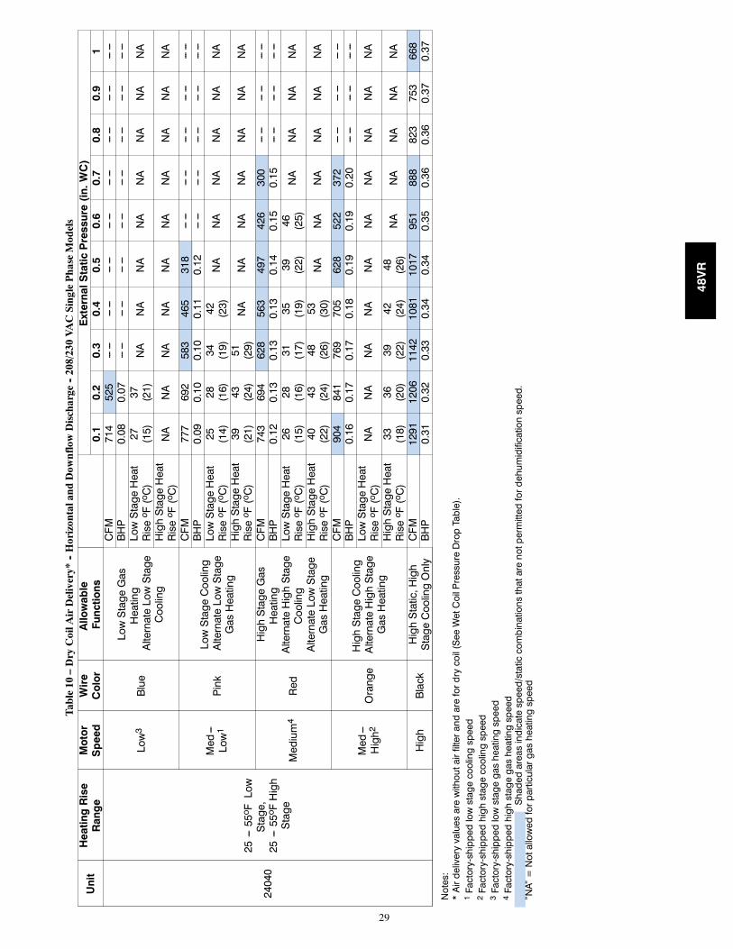
29
Table10
–DryCoilA
irDelivery*
--Horizontaland
Dow
nflowDischarge
--208/230VACSinglePhaseModels
Unit
HeatingRise
Range
Motor
Speed
Wire
Color
Allowable
Functions
ExternalStaticPressure(in.WC)
0.1
0.2
0.3
0.4
0.5
0.6
0.7
0.8
0.9
1
24040
25---55o FLow
Stage,
25---55o FHigh
Stage
Low3
Blue
LowStageGas
Heating
AlternateLowStage
Cooling
CFM
714
525
------
------
------
------
------
------
------
------
BHP
0.08
0.07
------
------
------
------
------
------
------
------
LowStageHeat
Riseo F(oC)
27 (15)
37 (21)
NA
NA
NA
NA
NA
NA
NA
NA
HighStageHeat
Riseo F(oC)
NA
NA
NA
NA
NA
NA
NA
NA
NA
NA
Med---
Low1
Pink
LowStageCooling
AlternateLowStage
GasHeating
CFM
777
692
583
465
318
------
------
------
------
------
BHP
0.09
0.10
0.10
0.11
0.12
------
------
------
------
------
LowStageHeat
Riseo F(oC)
25 (14)
28 (16)
34 (19)
42 (23)
NA
NA
NA
NA
NA
NA
HighStageHeat
Riseo F(oC)
39 (21)
43 (24)
51 (29)
NA
NA
NA
NA
NA
NA
NA
Medium4
Red
HighStageGas
Heating
AlternateHighStage
Cooling
AlternateLowStage
GasHeating
CFM
743
694
628
563
497
426
300
------
------
------
BHP
0.12
0.13
0.13
0.13
0.14
0.15
0.15
------
------
------
LowStageHeat
Riseo F(oC)
26 (15)
28 (16)
31 (17)
35 (19)
39 (22)
46 (25)
NA
NA
NA
NA
HighStageHeat
Riseo F(oC)
40 (22)
43 (24)
48 (26)
53 (30)
NA
NA
NA
NA
NA
NA
Med---
High2
Orange
HighStageCooling
AlternateHighStage
GasHeating
CFM
904
841
769
705
628
522
372
------
------
------
BHP
0.16
0.17
0.17
0.18
0.19
0.19
0.20
------
------
------
LowStageHeat
Riseo F(oC)
NA
NA
NA
NA
NA
NA
NA
NA
NA
NA
HighStageHeat
Riseo F(oC)
33 (18)
36 (20)
39 (22)
42 (24)
48 (26)
NA
NA
NA
NA
NA
High
Black
HighStatic,High
StageCoolingOnly
CFM
1291
1206
1142
1081
1017
951
888
823
753
668
BHP
0.31
0.32
0.33
0.34
0.34
0.35
0.36
0.36
0.37
0.37
Notes:
*Airdeliveryvaluesarewithoutairfilterandarefordrycoil(SeeWetCoilPressureDropTable).
1Factory-shippedlowstagecoolingspeed
2Factory-shippedhighstagecoolingspeed
3Factory-shippedlowstagegasheatingspeed
4Factory-shippedhighstagegasheatingspeed
Shadedareasindicatespeed/staticcombinationsthatarenotpermittedfordehumidificationspeed.
”NA”=Notallowedforparticulargasheatingspeed
48VR
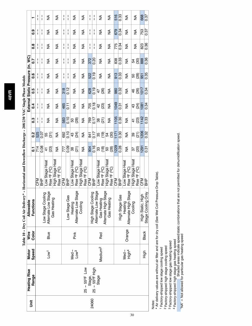
30
Table10
--DryCoilA
irDelivery*
--Horizontaland
Dow
nflowDischarge
--208/230VACSinglePhaseModels
Unit
HeatingRise
Range
Motor
Speed
Wire
Color
Allowable
Functions
ExternalStaticPressure(in.WC)
0.1
0.2
0.3
0.4
0.5
0.6
0.7
0.8
0.9
1
24060
25---55o FLow
Stage,
25---55o FHigh
Stage
Low1
Blue
LowStageCooling
AlternateLowStage
GasHeating
CFM
714
525
------
------
------
------
------
------
------
------
BHP
0.08
0.07
------
------
------
------
------
------
------
------
LowStageHeat
Riseo F(oC)
41 (23)
55 (31)
NA
NA
NA
NA
NA
NA
NA
NA
HighStageHeat
Riseo F(oC)
NA
NA
NA
NA
NA
NA
NA
NA
NA
NA
Med---
Low3
Pink
LowStageGas
Heating
AlternateLowStage
Cooling
CFM
777
692
583
465
318
------
------
------
------
------
BHP
0.09
0.10
0.10
0.11
0.12
------
------
------
------
------
LowStageHeat
Riseo F(oC)
38 (21)
43 (24)
50 (28)
NA
NA
NA
NA
NA
NA
NA
HighStageHeat
Riseo F(oC)
NA
NA
NA
NA
NA
NA
NA
NA
NA
NA
Medium2
Red
HighStageCooling
AlternateLowStage
GasHeating
AlternateHighStage
GasHeating
CFM
904
841
769
705
628
522
372
------
------
------
BHP
0.16
0.17
0.17
0.18
0.19
0.19
0.20
------
------
------
LowStageHeat
Riseo F(oC)
33 (18)
35 (19)
38 (21)
42 (23)
47 (26)
NA
NA
NA
NA
NA
HighStageHeat
Riseo F(oC)
50 (28)
54 (30)
NA
NA
NA
NA
NA
NA
NA
NA
Med---
High4
Orange
HighStageGas
Heating
AlternateHighStage
Cooling
CFM
1229
1171
1105
1049
980
913
838
775
679
516
BHP
0.28
0.30
0.30
0.31
0.32
0.33
0.33
0.34
0.34
0.33
LowStageHeat
Riseo F(oC)
NA
NA
NA
NA
NA
NA
NA
NA
NA
NA
HighStageHeat
Riseo F(oC)
37 (20)
39 (21)
41 (23)
43 (24)
46 (26)
50 (28)
54 (30)
NA
NA
NA
High
Black
HighStatic,High
StageCoolingOnly
CFM
1291
1206
1142
1081
1017
951
888
823
753
668
BHP
0.31
0.32
0.33
0.34
0.34
0.35
0.36
0.36
0.37
0.37
Notes:
*Airdeliveryvaluesarewithoutairfilterandarefordrycoil(SeeWetCoilPressureDropTable).
1Factory-shippedlowstagecoolingspeed
2Factory-shippedhighstagecoolingspeed
3Factory-shippedlowstagegasheatingspeed
4Factory-shippedhighstagegasheatingspeed
Shadedareasindicatespeed/staticcombinationsthatarenotpermittedfordehumidificationspeed.
”NA”=Notallowedforparticulargasheatingspeed
48VR
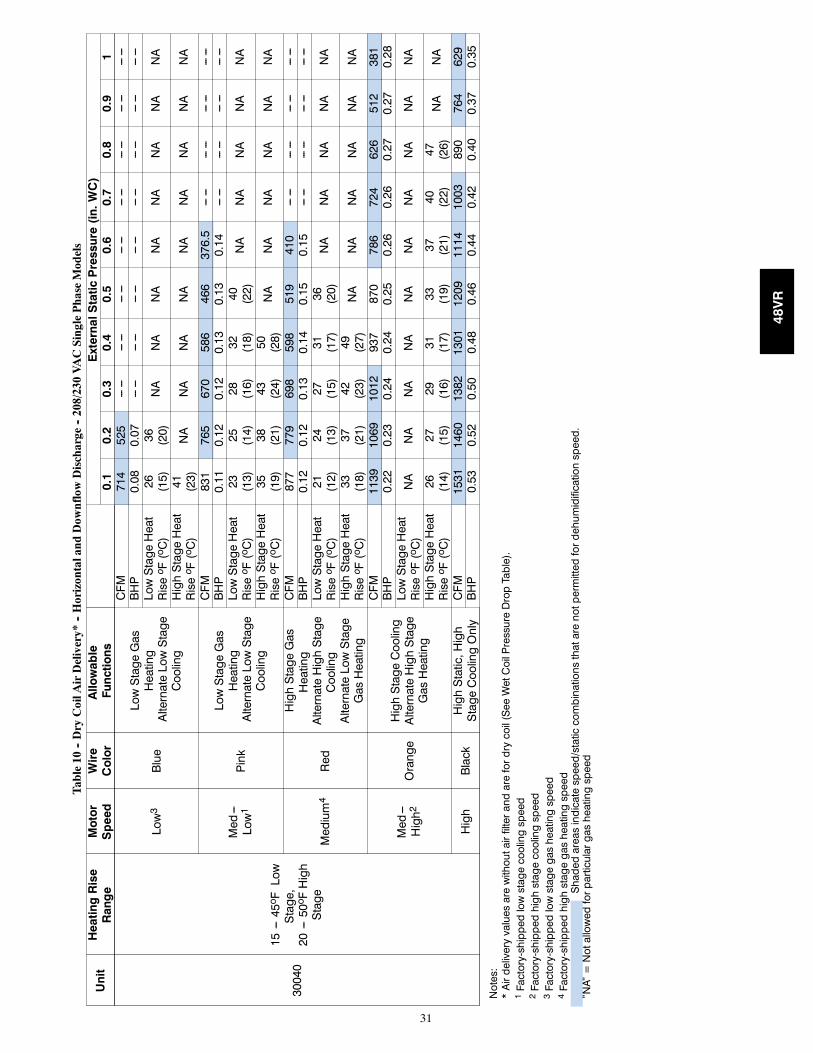
31
Table10
--DryCoilA
irDelivery*
--Horizontaland
Dow
nflowDischarge
--208/230VACSinglePhaseModels
Unit
HeatingRise
Range
Motor
Speed
Wire
Color
Allowable
Functions
ExternalStaticPressure(in.WC)
0.1
0.2
0.3
0.4
0.5
0.6
0.7
0.8
0.9
1
30040
15---45o FLow
Stage,
20---50o FHigh
Stage
Low3
Blue
LowStageGas
Heating
AlternateLowStage
Cooling
CFM
714
525
------
------
------
------
------
------
------
------
BHP
0.08
0.07
------
------
------
------
------
------
------
------
LowStageHeat
Riseo F(oC)
26 (15)
36 (20)
NA
NA
NA
NA
NA
NA
NA
NA
HighStageHeat
Riseo F(oC)
41 (23)
NA
NA
NA
NA
NA
NA
NA
NA
NA
Med---
Low1
Pink
LowStageGas
Heating
AlternateLowStage
Cooling
CFM
831
765
670
586
466
376.5
------
------
------
------
BHP
0.11
0.12
0.12
0.13
0.13
0.14
------
------
------
------
LowStageHeat
Riseo F(oC)
23 (13)
25 (14)
28 (16)
32 (18)
40 (22)
NA
NA
NA
NA
NA
HighStageHeat
Riseo F(oC)
35 (19)
38 (21)
43 (24)
50 (28)
NA
NA
NA
NA
NA
NA
Medium4
Red
HighStageGas
Heating
AlternateHighStage
Cooling
AlternateLowStage
GasHeating
CFM
877
779
698
598
519
410
------
------
------
------
BHP
0.12
0.12
0.13
0.14
0.15
0.15
------
------
------
------
LowStageHeat
Riseo F(oC)
21 (12)
24 (13)
27 (15)
31 (17)
36 (20)
NA
NA
NA
NA
NA
HighStageHeat
Riseo F(oC)
33 (18)
37 (21)
42 (23)
49 (27)
NA
NA
NA
NA
NA
NA
Med---
High2
Orange
HighStageCooling
AlternateHighStage
GasHeating
CFM
1139
1069
1012
937
870
786
724
626
512
381
BHP
0.22
0.23
0.24
0.24
0.25
0.26
0.26
0.27
0.27
0.28
LowStageHeat
Riseo F(oC)
NA
NA
NA
NA
NA
NA
NA
NA
NA
NA
HighStageHeat
Riseo F(oC)
26 (14)
27 (15)
29 (16)
31 (17)
33 (19)
37 (21)
40 (22)
47 (26)
NA
NA
High
Black
HighStatic,High
StageCoolingOnly
CFM
1531
1460
1382
1301
1209
1114
1003
890
764
629
BHP
0.53
0.52
0.50
0.48
0.46
0.44
0.42
0.40
0.37
0.35
Notes:
*Airdeliveryvaluesarewithoutairfilterandarefordrycoil(SeeWetCoilPressureDropTable).
1Factory-shippedlowstagecoolingspeed
2Factory-shippedhighstagecoolingspeed
3Factory-shippedlowstagegasheatingspeed
4Factory-shippedhighstagegasheatingspeed
Shadedareasindicatespeed/staticcombinationsthatarenotpermittedfordehumidificationspeed.
”NA”=Notallowedforparticulargasheatingspeed
48VR
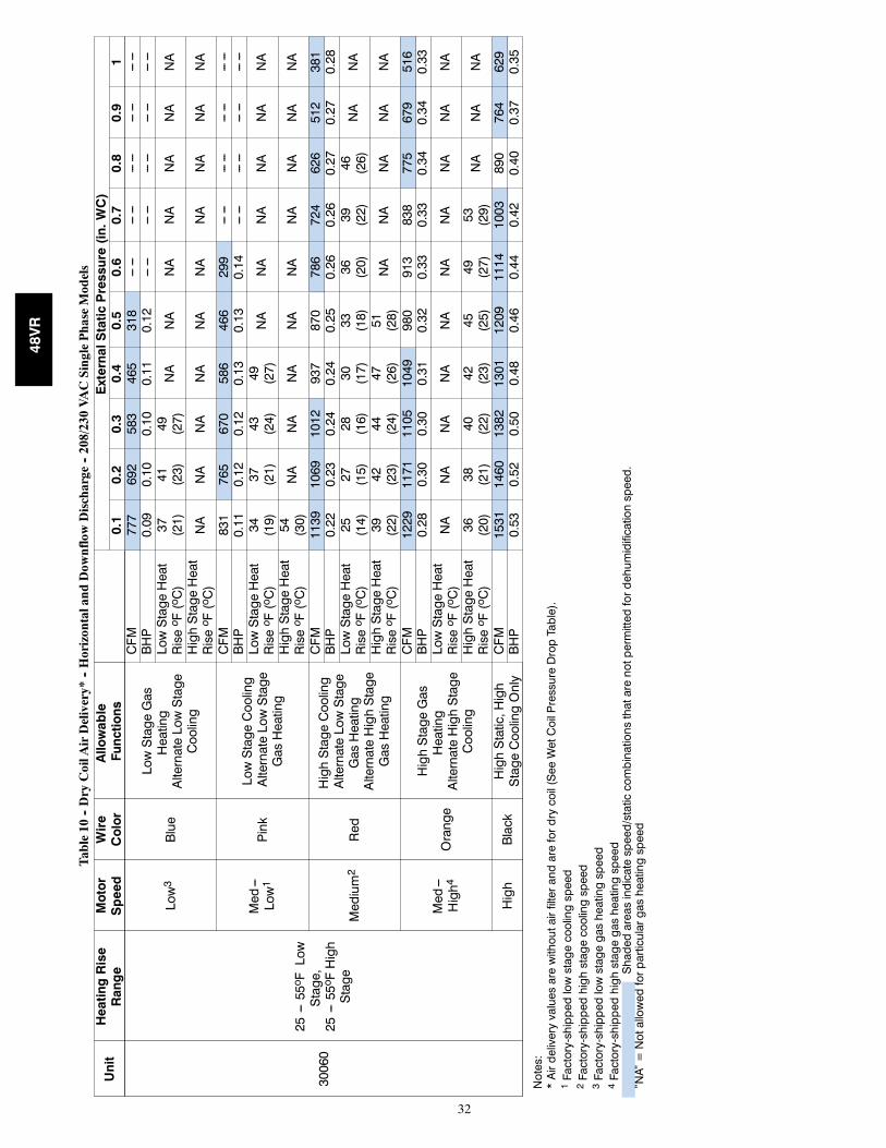
32
Table10
--DryCoilA
irDelivery*
--Horizontaland
Dow
nflowDischarge
--208/230VACSinglePhaseModels
Unit
HeatingRise
Range
Motor
Speed
Wire
Color
Allowable
Functions
ExternalStaticPressure(in.WC)
0.1
0.2
0.3
0.4
0.5
0.6
0.7
0.8
0.9
1
30060
25---55o FLow
Stage,
25---55o FHigh
Stage
Low3
Blue
LowStageGas
Heating
AlternateLowStage
Cooling
CFM
777
692
583
465
318
------
------
------
------
------
BHP
0.09
0.10
0.10
0.11
0.12
------
------
------
------
------
LowStageHeat
Riseo F(oC)
37 (21)
41 (23)
49 (27)
NA
NA
NA
NA
NA
NA
NA
HighStageHeat
Riseo F(oC)
NA
NA
NA
NA
NA
NA
NA
NA
NA
NA
Med---
Low1
Pink
LowStageCooling
AlternateLowStage
GasHeating
CFM
831
765
670
586
466
299
------
------
------
------
BHP
0.11
0.12
0.12
0.13
0.13
0.14
------
------
------
------
LowStageHeat
Riseo F(oC)
34 (19)
37 (21)
43 (24)
49 (27)
NA
NA
NA
NA
NA
NA
HighStageHeat
Riseo F(oC)
54 (30)
NA
NA
NA
NA
NA
NA
NA
NA
NA
Medium2
Red
HighStageCooling
AlternateLowStage
GasHeating
AlternateHighStage
GasHeating
CFM
1139
1069
1012
937
870
786
724
626
512
381
BHP
0.22
0.23
0.24
0.24
0.25
0.26
0.26
0.27
0.27
0.28
LowStageHeat
Riseo F(oC)
25 (14)
27 (15)
28 (16)
30 (17)
33 (18)
36 (20)
39 (22)
46 (26)
NA
NA
HighStageHeat
Riseo F(oC)
39 (22)
42 (23)
44 (24)
47 (26)
51 (28)
NA
NA
NA
NA
NA
Med---
High4
Orange
HighStageGas
Heating
AlternateHighStage
Cooling
CFM
1229
1171
1105
1049
980
913
838
775
679
516
BHP
0.28
0.30
0.30
0.31
0.32
0.33
0.33
0.34
0.34
0.33
LowStageHeat
Riseo F(oC)
NA
NA
NA
NA
NA
NA
NA
NA
NA
NA
HighStageHeat
Riseo F(oC)
36 (20)
38 (21)
40 (22)
42 (23)
45 (25)
49 (27)
53 (29)
NA
NA
NA
High
Black
HighStatic,High
StageCoolingOnly
CFM
1531
1460
1382
1301
1209
1114
1003
890
764
629
BHP
0.53
0.52
0.50
0.48
0.46
0.44
0.42
0.40
0.37
0.35
Notes:
*Airdeliveryvaluesarewithoutairfilterandarefordrycoil(SeeWetCoilPressureDropTable).
1Factory-shippedlowstagecoolingspeed
2Factory-shippedhighstagecoolingspeed
3Factory-shippedlowstagegasheatingspeed
4Factory-shippedhighstagegasheatingspeed
Shadedareasindicatespeed/staticcombinationsthatarenotpermittedfordehumidificationspeed.
”NA”=Notallowedforparticulargasheatingspeed
48VR
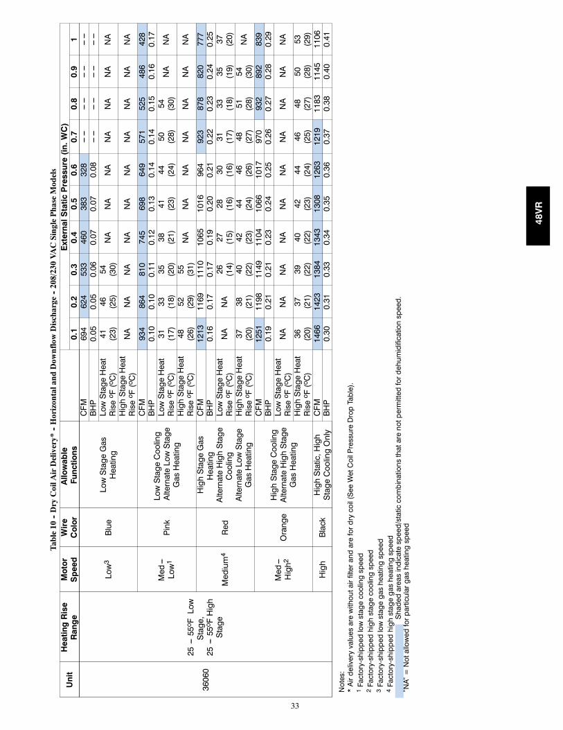
33
Table10
--DryCoilA
irDelivery*
--Horizontaland
Dow
nflowDischarge
--208/230VACSinglePhaseModels
Unit
HeatingRise
Range
Motor
Speed
Wire
Color
Allowable
Functions
ExternalStaticPressure(in.WC)
0.1
0.2
0.3
0.4
0.5
0.6
0.7
0.8
0.9
1
36060
25---55o FLow
Stage,
25---55o FHigh
Stage
Low3
Blue
LowStageGas
Heating
CFM
694
624
533
460
383
328
------
------
------
------
BHP
0.05
0.05
0.06
0.07
0.07
0.08
------
------
------
------
LowStageHeat
Riseo F(oC)
41 (23)
46 (25)
54 (30)
NA
NA
NA
NA
NA
NA
NA
HighStageHeat
Riseo F(oC)
NA
NA
NA
NA
NA
NA
NA
NA
NA
NA
Med---
Low1
Pink
LowStageCooling
AlternateLowStage
GasHeating
CFM
934
864
810
745
698
649
571
525
486
428
BHP
0.10
0.10
0.11
0.12
0.13
0.14
0.14
0.15
0.16
0.17
LowStageHeat
Riseo F(oC)
31 (17)
33 (18)
35 (20)
38 (21)
41 (23)
44 (24)
50 (28)
54 (30)
NA
NA
HighStageHeat
Riseo F(oC)
48 (26)
52 (29)
55 (31)
NA
NA
NA
NA
NA
NA
NA
Medium4
Red
HighStageGas
Heating
AlternateHighStage
Cooling
AlternateLowStage
GasHeating
CFM
1213
1169
1110
1065
1016
964
923
878
820
777
BHP
0.16
0.17
0.17
0.19
0.20
0.21
0.22
0.23
0.24
0.25
LowStageHeat
Riseo F(oC)
NA
NA
26 (14)
27 (15)
28 (16)
30 (16)
31 (17)
33 (18)
35 (19)
37 (20)
HighStageHeat
Riseo F(oC)
37 (20)
38 (21)
40 (22)
42 (23)
44 (24)
46 (26)
48 (27)
51 (28)
54 (30)
NA
Med---
High2
Orange
HighStageCooling
AlternateHighStage
GasHeating
CFM
1251
1198
1149
1104
1066
1017
970
932
892
839
BHP
0.19
0.21
0.21
0.23
0.24
0.25
0.26
0.27
0.28
0.29
LowStageHeat
Riseo F(oC)
NA
NA
NA
NA
NA
NA
NA
NA
NA
NA
HighStageHeat
Riseo F(oC)
36 (20)
37 (21)
39 (22)
40 (22)
42 (23)
44 (24)
46 (25)
48 (27)
50 (28)
53 (29)
High
Black
HighStatic,High
StageCoolingOnly
CFM
1466
1423
1384
1343
1308
1263
1219
1183
1145
1106
BHP
0.30
0.31
0.33
0.34
0.35
0.36
0.37
0.38
0.40
0.41
Notes:
*Airdeliveryvaluesarewithoutairfilterandarefordrycoil(SeeWetCoilPressureDropTable).
1Factory-shippedlowstagecoolingspeed
2Factory-shippedhighstagecoolingspeed
3Factory-shippedlowstagegasheatingspeed
4Factory-shippedhighstagegasheatingspeed
Shadedareasindicatespeed/staticcombinationsthatarenotpermittedfordehumidificationspeed.
”NA”=Notallowedforparticulargasheatingspeed
48VR
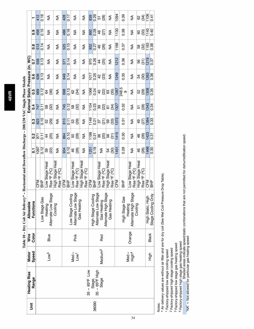
34
Table10
--DryCoilA
irDelivery*
--Horizontaland
Dow
nflowDischarge
--208/230VACSinglePhaseModels
Unit
HeatingRise
Range
Motor
Speed
Wire
Color
Allowable
Functions
ExternalStaticPressure(in.WC)
0.1
0.2
0.3
0.4
0.5
0.6
0.7
0.8
0.9
1
36090
35---65o FLow
Stage,
35---65o FHigh
Stage
Low3
Blue
LowStageGas
Heating
AlternateLowStage
Cooling
CFM
1097
971
823
747
669
636
558
513
456
412
BHP
0.12
0.11
0.10
0.11
0.12
0.13
0.13
0.14
0.15
0.16
LowStageHeat
Riseo F(oC)
39 (22)
44 (25)
52 (29)
58 (32)
64 (36)
NA
NA
NA
NA
NA
HighStageHeat
Riseo F(oC)
NA
NA
NA
NA
NA
NA
NA
NA
NA
NA
Med---
Low1
Pink
LowStageCooling
AlternateLowStage
GasHeating
CFM
934
864
810
745
698
649
571
525
486
428
BHP
0.10
0.10
0.11
0.12
0.13
0.14
0.14
0.15
0.16
0.17
LowStageHeat
Riseo F(oC)
46 (26)
50 (28)
53 (29)
58 (32)
62 (34)
NA
NA
NA
NA
NA
HighStageHeat
Riseo F(oC)
NA
NA
NA
NA
NA
NA
NA
NA
NA
NA
Medium2
Red
HighStageCooling
AlternateLowStage
GasHeating
AlternateHighStage
GasHeating
CFM
1251
1198
1149
1104
1066
1017
970
932
892
839
BHP
0.19
0.21
0.21
0.23
0.24
0.25
0.26
0.27
0.28
0.29
LowStageHeat
Riseo F(oC)
NA
36 (20)
37 (21)
39 (22)
40 (22)
42 (23)
44 (25)
46 (26)
48 (27)
51 (28)
HighStageHeat
Riseo F(oC)
54 (30)
56 (31)
59 (33)
61 (34)
63 (35)
NA
NA
NA
NA
NA
Med---
High4
Orange
HighStageGas
Heating
AlternateHighStage
Cooling
CFM
1451
1415
1372
1327
1287
1249
1212
1168
1130
1094
BHP
0.29
0.30
0.31
0.32
248.59
0.35
0.36
0.37
0.38
0.39
LowStageHeat
Riseo F(oC)
NA
NA
NA
NA
NA
NA
NA
NA
NA
NA
HighStageHeat
Riseo F(oC)
46 (26)
48 (26)
49 (27)
51 (28)
52 (29)
54 (30)
56 (31)
58 (32)
60 (33)
62 (34)
High
Black
HighStatic,High
StageCoolingOnly
CFM
1466
1423
1384
1343
1308
1263
1219
1183
1145
1106
BHP
0.30
0.31
0.33
0.34
0.35
0.36
0.37
0.38
0.40
0.41
Notes:
*Airdeliveryvaluesarewithoutairfilterandarefordrycoil(SeeWetCoilPressureDropTable).
1Factory-shippedlowstagecoolingspeed
2Factory-shippedhighstagecoolingspeed
3Factory-shippedlowstagegasheatingspeed
4Factory-shippedhighstagegasheatingspeed
Shadedareasindicatespeed/staticcombinationsthatarenotpermittedfordehumidificationspeed.
”NA”=Notallowedforparticulargasheatingspeed
48VR
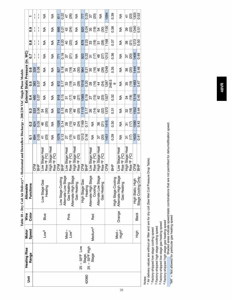
35
Table10
--DryCoilA
irDelivery*
--Horizontaland
Dow
nflowDischarge
--208/230VACSinglePhaseModels
Unit
HeatingRise
Range
Motor
Speed
Wire
Color
Allowable
Functions
ExternalStaticPressure(in.WC)
0.1
0.2
0.3
0.4
0.5
0.6
0.7
0.8
0.9
1
42060
25---55o FLow
Stage,
25---55o FHigh
Stage
Low3
Blue
LowStageGas
Heating
CFM
694
624
533
460
383
328
------
------
------
------
BHP
0.05
0.05
0.06
0.07
0.07
0.08
------
------
------
------
LowStageHeat
Riseo F(oC)
41 (23)
46 (25)
54 (30)
NA
NA
NA
NA
NA
NA
NA
HighStageHeat
Riseo F(oC)
NA
NA
NA
NA
NA
NA
NA
NA
NA
NA
Med---
Low1
Pink
LowStageCooling
AlternateLowStage
GasHeating
AlternateHighStage
GasHeating
CFM
1076
1026
972
918
872
827
771
714
666
611
BHP
0.13
0.14
0.15
0.15
0.17
0.18
0.18
0.20
0.21
0.22
LowStageHeat
Riseo F(oC)
27 (15)
28 (15)
29 (16)
31 (17)
33 (18)
35 (19)
37 (21)
40 (22)
43 (24)
47 (26)
HighStageHeat
Riseo F(oC)
41 (23)
43 (24)
46 (25)
48 (27)
51 (28)
54 (30)
NA
NA
NA
NA
Medium4
Red
HighStageGas
Heating
AlternateHighStage
Cooling
AlternateLowStage
GasHeating
CFM
1213
1169
1110
1065
1016
964
923
878
820
777
BHP
0.16
0.17
0.17
0.19
0.20
0.21
0.22
0.23
0.24
0.25
LowStageHeat
Riseo F(oC)
NA
NA
26 (14)
27 (15)
28 (16)
30 (16)
31 (17)
33 (18)
35 (19)
37 (20)
HighStageHeat
Riseo F(oC)
37 (20)
38 (21)
40 (22)
42 (23)
44 (24)
46 (26)
48 (27)
51 (28)
54 (30)
NA
Med---
High2
Orange
HighStageCooling
AlternateHighStage
GasHeating
CFM
1451
1415
1372
1327
1287
1249
1212
1168
1130
1094
BHP
0.29
0.30
0.31
0.32
248.59
0.35
0.36
0.37
0.38
0.39
LowStageHeat
Riseo F(oC)
NA
NA
NA
NA
NA
NA
NA
NA
NA
NA
HighStageHeat
Riseo F(oC)
31 (17)
31 (17)
32 (18)
34 (18)
35 (19)
36 (20)
37 (20)
38 (21)
39 (22)
41 (23)
High
Black
HighStatic,High
StageCoolingOnly
CFM
1633
1590
1552
1518
1483
1444
1406
1372
1340
1303
BHP
0.41
0.43
0.44
0.45
0.47
0.48
0.49
0.50
0.51
0.53
Notes:
*Airdeliveryvaluesarewithoutairfilterandarefordrycoil(SeeWetCoilPressureDropTable).
1Factory-shippedlowstagecoolingspeed
2Factory-shippedhighstagecoolingspeed
3Factory-shippedlowstagegasheatingspeed
4Factory-shippedhighstagegasheatingspeed
Shadedareasindicatespeed/staticcombinationsthatarenotpermittedfordehumidificationspeed.
”NA”=Notallowedforparticulargasheatingspeed
48VR
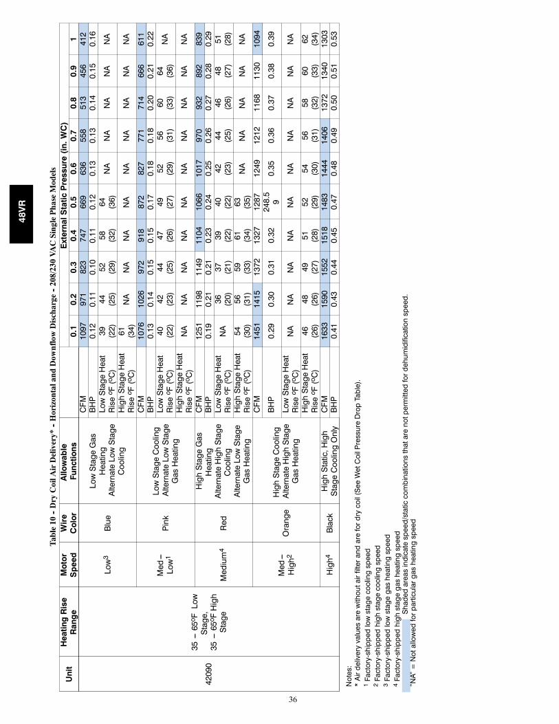
36
Table10
--DryCoilA
irDelivery*
--Horizontaland
Dow
nflowDischarge
--208/230VACSinglePhaseModels
Unit
HeatingRise
Range
Motor
Speed
Wire
Color
Allowable
Functions
ExternalStaticPressure(in.WC)
0.1
0.2
0.3
0.4
0.5
0.6
0.7
0.8
0.9
1
42090
35---65o FLow
Stage,
35---65o FHigh
Stage
Low3
Blue
LowStageGas
Heating
AlternateLowStage
Cooling
CFM
1097
971
823
747
669
636
558
513
456
412
BHP
0.12
0.11
0.10
0.11
0.12
0.13
0.13
0.14
0.15
0.16
LowStageHeat
Riseo F(oC)
39 (22)
44 (25)
52 (29)
58 (32)
64 (36)
NA
NA
NA
NA
NA
HighStageHeat
Riseo F(oC)
61 (34)
NA
NA
NA
NA
NA
NA
NA
NA
NA
Med---
Low1
Pink
LowStageCooling
AlternateLowStage
GasHeating
CFM
1076
1026
972
918
872
827
771
714
666
611
BHP
0.13
0.14
0.15
0.15
0.17
0.18
0.18
0.20
0.21
0.22
LowStageHeat
Riseo F(oC)
40 (22)
42 (23)
44 (25)
47 (26)
49 (27)
52 (29)
56 (31)
60 (33)
64 (36)
NA
HighStageHeat
Riseo F(oC)
NA
NA
NA
NA
NA
NA
NA
NA
NA
NA
Medium4
Red
HighStageGas
Heating
AlternateHighStage
Cooling
AlternateLowStage
GasHeating
CFM
1251
1198
1149
1104
1066
1017
970
932
892
839
BHP
0.19
0.21
0.21
0.23
0.24
0.25
0.26
0.27
0.28
0.29
LowStageHeat
Riseo F(oC)
NA
36 (20)
37 (21)
39 (22)
40 (22)
42 (23)
44 (25)
46 (26)
48 (27)
51 (28)
HighStageHeat
Riseo F(oC)
54 (30)
56 (31)
59 (33)
61 (34)
63 (35)
NA
NA
NA
NA
NA
Med---
High2
Orange
HighStageCooling
AlternateHighStage
GasHeating
CFM
1451
1415
1372
1327
1287
1249
1212
1168
1130
1094
BHP
0.29
0.30
0.31
0.32
248.59
0.35
0.36
0.37
0.38
0.39
LowStageHeat
Riseo F(oC)
NA
NA
NA
NA
NA
NA
NA
NA
NA
NA
HighStageHeat
Riseo F(oC)
46 (26)
48 (26)
49 (27)
51 (28)
52 (29)
54 (30)
56 (31)
58 (32)
60 (33)
62 (34)
High4
Black
HighStatic,High
StageCoolingOnly
CFM
1633
1590
1552
1518
1483
1444
1406
1372
1340
1303
BHP
0.41
0.43
0.44
0.45
0.47
0.48
0.49
0.50
0.51
0.53
Notes:
*Airdeliveryvaluesarewithoutairfilterandarefordrycoil(SeeWetCoilPressureDropTable).
1Factory-shippedlowstagecoolingspeed
2Factory-shippedhighstagecoolingspeed
3Factory-shippedlowstagegasheatingspeed
4Factory-shippedhighstagegasheatingspeed
Shadedareasindicatespeed/staticcombinationsthatarenotpermittedfordehumidificationspeed.
”NA”=Notallowedforparticulargasheatingspeed
48VR
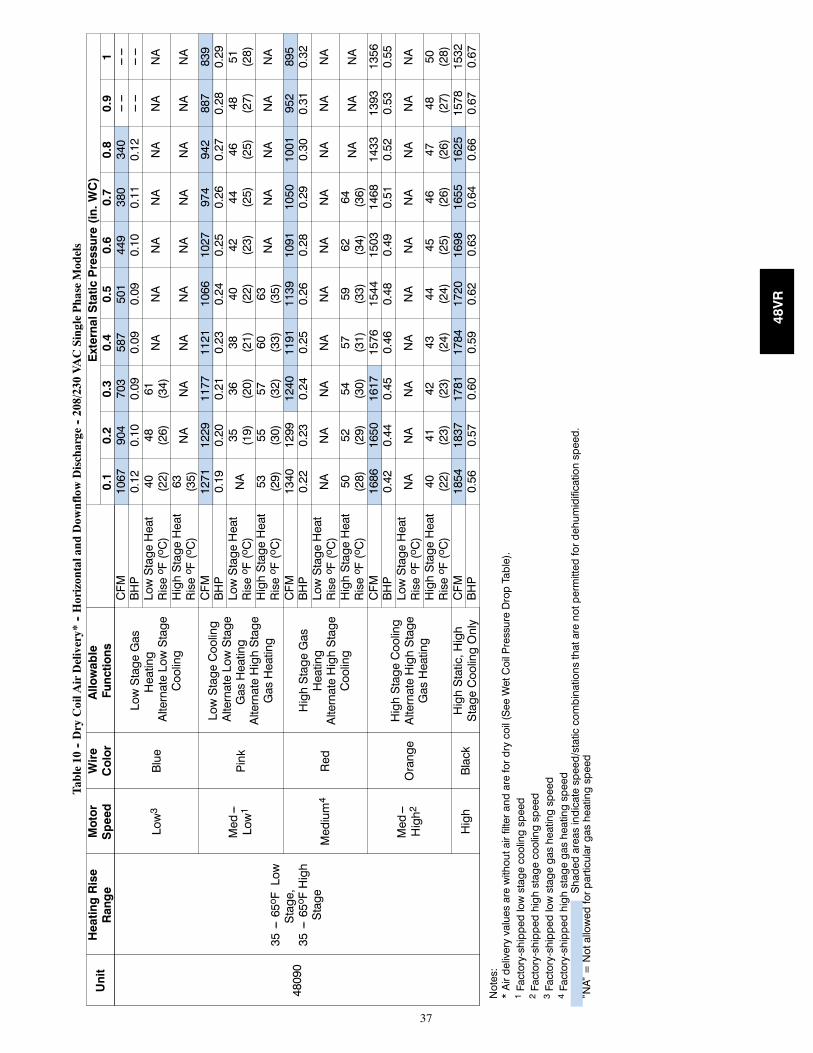
37
Table10
--DryCoilA
irDelivery*
--Horizontaland
Dow
nflowDischarge
--208/230VACSinglePhaseModels
Unit
HeatingRise
Range
Motor
Speed
Wire
Color
Allowable
Functions
ExternalStaticPressure(in.WC)
0.1
0.2
0.3
0.4
0.5
0.6
0.7
0.8
0.9
1
48090
35---65o FLow
Stage,
35---65o FHigh
Stage
Low3
Blue
LowStageGas
Heating
AlternateLowStage
Cooling
CFM
1067
904
703
587
501
449
380
340
------
------
BHP
0.12
0.10
0.09
0.09
0.09
0.10
0.11
0.12
------
------
LowStageHeat
Riseo F(oC)
40 (22)
48 (26)
61 (34)
NA
NA
NA
NA
NA
NA
NA
HighStageHeat
Riseo F(oC)
63 (35)
NA
NA
NA
NA
NA
NA
NA
NA
NA
Med---
Low1
Pink
LowStageCooling
AlternateLowStage
GasHeating
AlternateHighStage
GasHeating
CFM
1271
1229
1177
1121
1066
1027
974
942
887
839
BHP
0.19
0.20
0.21
0.23
0.24
0.25
0.26
0.27
0.28
0.29
LowStageHeat
Riseo F(oC)
NA
35 (19)
36 (20)
38 (21)
40 (22)
42 (23)
44 (25)
46 (25)
48 (27)
51 (28)
HighStageHeat
Riseo F(oC)
53 (29)
55 (30)
57 (32)
60 (33)
63 (35)
NA
NA
NA
NA
NA
Medium4
Red
HighStageGas
Heating
AlternateHighStage
Cooling
CFM
1340
1299
1240
1191
1139
1091
1050
1001
952
895
BHP
0.22
0.23
0.24
0.25
0.26
0.28
0.29
0.30
0.31
0.32
LowStageHeat
Riseo F(oC)
NA
NA
NA
NA
NA
NA
NA
NA
NA
NA
HighStageHeat
Riseo F(oC)
50 (28)
52 (29)
54 (30)
57 (31)
59 (33)
62 (34)
64 (36)
NA
NA
NA
Med---
High2
Orange
HighStageCooling
AlternateHighStage
GasHeating
CFM
1686
1650
1617
1576
1544
1503
1468
1433
1393
1356
BHP
0.42
0.44
0.45
0.46
0.48
0.49
0.51
0.52
0.53
0.55
LowStageHeat
Riseo F(oC)
NA
NA
NA
NA
NA
NA
NA
NA
NA
NA
HighStageHeat
Riseo F(oC)
40 (22)
41 (23)
42 (23)
43 (24)
44 (24)
45 (25)
46 (26)
47 (26)
48 (27)
50 (28)
High
Black
HighStatic,High
StageCoolingOnly
CFM
1854
1837
1781
1784
1720
1698
1655
1625
1578
1532
BHP
0.56
0.57
0.60
0.59
0.62
0.63
0.64
0.66
0.67
0.67
Notes:
*Airdeliveryvaluesarewithoutairfilterandarefordrycoil(SeeWetCoilPressureDropTable).
1Factory-shippedlowstagecoolingspeed
2Factory-shippedhighstagecoolingspeed
3Factory-shippedlowstagegasheatingspeed
4Factory-shippedhighstagegasheatingspeed
Shadedareasindicatespeed/staticcombinationsthatarenotpermittedfordehumidificationspeed.
”NA”=Notallowedforparticulargasheatingspeed
48VR
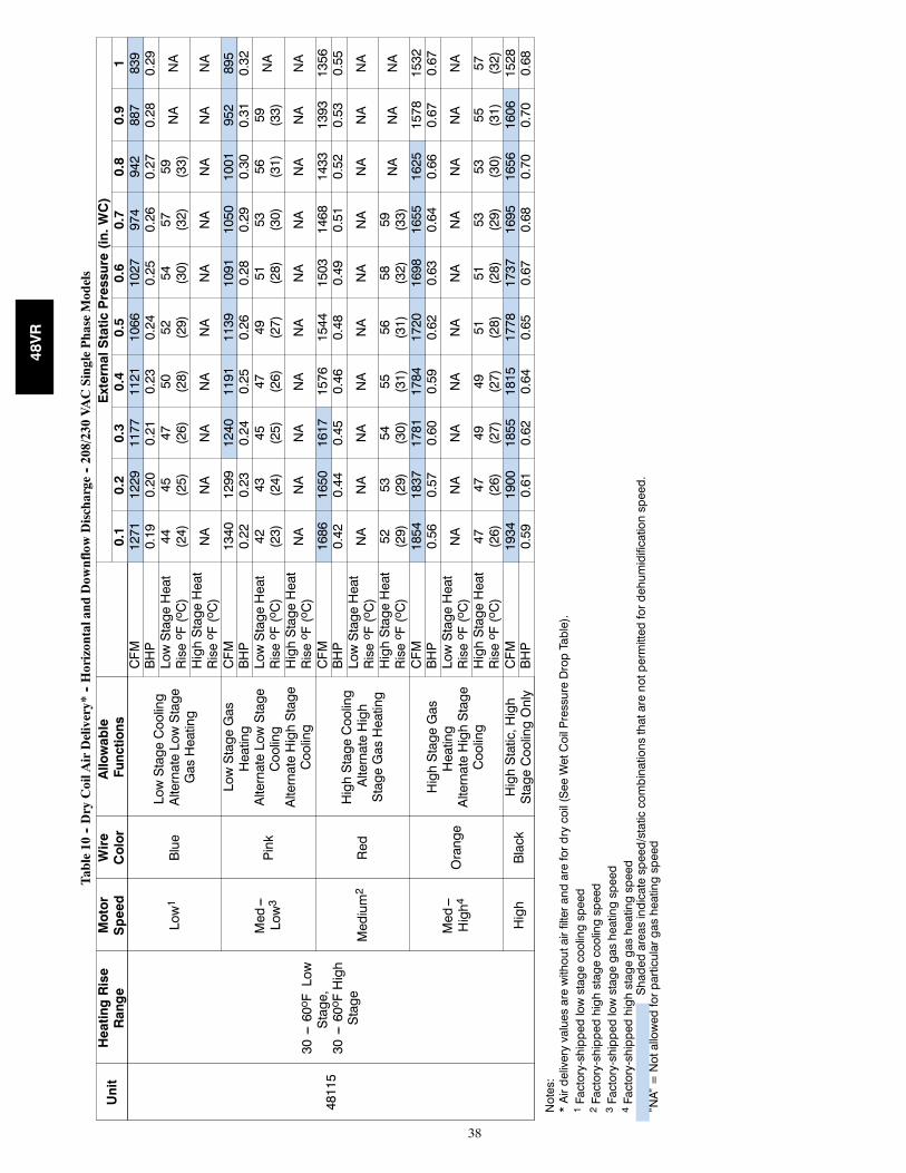
38
Table10
--DryCoilA
irDelivery*
--Horizontaland
Dow
nflowDischarge
--208/230VACSinglePhaseModels
Unit
HeatingRise
Range
Motor
Speed
Wire
Color
Allowable
Functions
ExternalStaticPressure(in.WC)
0.1
0.2
0.3
0.4
0.5
0.6
0.7
0.8
0.9
1
48115
30---60o FLow
Stage,
30---60o FHigh
Stage
Low1
Blue
LowStageCooling
AlternateLowStage
GasHeating
CFM
1271
1229
1177
1121
1066
1027
974
942
887
839
BHP
0.19
0.20
0.21
0.23
0.24
0.25
0.26
0.27
0.28
0.29
LowStageHeat
Riseo F(oC)
44 (24)
45 (25)
47 (26)
50 (28)
52 (29)
54 (30)
57 (32)
59 (33)
NA
NA
HighStageHeat
Riseo F(oC)
NA
NA
NA
NA
NA
NA
NA
NA
NA
NA
Med---
Low3
Pink
LowStageGas
Heating
AlternateLowStage
Cooling
AlternateHighStage
Cooling
CFM
1340
1299
1240
1191
1139
1091
1050
1001
952
895
BHP
0.22
0.23
0.24
0.25
0.26
0.28
0.29
0.30
0.31
0.32
LowStageHeat
Riseo F(oC)
42 (23)
43 (24)
45 (25)
47 (26)
49 (27)
51 (28)
53 (30)
56 (31)
59 (33)
NA
HighStageHeat
Riseo F(oC)
NA
NA
NA
NA
NA
NA
NA
NA
NA
NA
Medium2
Red
HighStageCooling
AlternateHigh
StageGasHeating
CFM
1686
1650
1617
1576
1544
1503
1468
1433
1393
1356
BHP
0.42
0.44
0.45
0.46
0.48
0.49
0.51
0.52
0.53
0.55
LowStageHeat
Riseo F(oC)
NA
NA
NA
NA
NA
NA
NA
NA
NA
NA
HighStageHeat
Riseo F(oC)
52 (29)
53 (29)
54 (30)
55 (31)
56 (31)
58 (32)
59 (33)
NA
NA
NA
Med---
High4
Orange
HighStageGas
Heating
AlternateHighStage
Cooling
CFM
1854
1837
1781
1784
1720
1698
1655
1625
1578
1532
BHP
0.56
0.57
0.60
0.59
0.62
0.63
0.64
0.66
0.67
0.67
LowStageHeat
Riseo F(oC)
NA
NA
NA
NA
NA
NA
NA
NA
NA
NA
HighStageHeat
Riseo F(oC)
47 (26)
47 (26)
49 (27)
49 (27)
51 (28)
51 (28)
53 (29)
53 (30)
55 (31)
57 (32)
High
Black
HighStatic,High
StageCoolingOnly
CFM
1934
1900
1855
1815
1778
1737
1695
1656
1606
1528
BHP
0.59
0.61
0.62
0.64
0.65
0.67
0.68
0.70
0.70
0.68
Notes:
*Airdeliveryvaluesarewithoutairfilterandarefordrycoil(SeeWetCoilPressureDropTable).
1Factory-shippedlowstagecoolingspeed
2Factory-shippedhighstagecoolingspeed
3Factory-shippedlowstagegasheatingspeed
4Factory-shippedhighstagegasheatingspeed
Shadedareasindicatespeed/staticcombinationsthatarenotpermittedfordehumidificationspeed.
”NA”=Notallowedforparticulargasheatingspeed
48VR
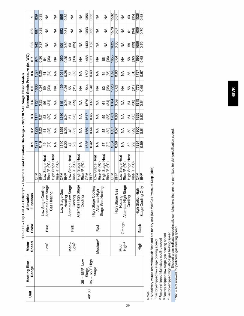
39
Table10
--DryCoilA
irDelivery*
--Horizontaland
Dow
nflowDischarge
--208/230VACSinglePhaseModels
Unit
HeatingRise
Range
Motor
Speed
Wire
Color
Allowable
Functions
ExternalStaticPressure(in.WC)
0.1
0.2
0.3
0.4
0.5
0.6
0.7
0.8
0.9
1
48130
35---65o FLow
Stage,
35---65o FHigh
Stage
Low1
Blue
LowStageCooling
AlternateLowStage
GasHeating
CFM
1271
1229
1177
1121
1066
1027
974
942
887
839
BHP
0.19
0.20
0.21
0.23
0.24
0.25
0.26
0.27
0.28
0.29
LowStageHeat
Riseo F(oC)
49 (27)
51 (28)
53 (30)
56 (31)
59 (33)
61 (34)
64 (36)
NA
NA
NA
HighStageHeat
Riseo F(oC)
NA
NA
NA
NA
NA
NA
NA
NA
NA
NA
Med---
Low3
Pink
LowStageGas
Heating
AlternateLowStage
Cooling
AlternateHighStage
Cooling
CFM
1340
1299
1240
1191
1139
1091
1050
1001
952
895
BHP
0.22
0.23
0.24
0.25
0.26
0.28
0.29
0.30
0.31
0.32
LowStageHeat
Riseo F(oC)
47 (26)
48 (27)
51 (28)
53 (29)
55 (31)
57 (32)
60 (33)
63 (35)
NA
NA
HighStageHeat
Riseo F(oC)
NA
NA
NA
NA
NA
NA
NA
NA
NA
NA
Medium2
Red
HighStageCooling
AlternateHigh
StageGasHeating
CFM
1686
1650
1617
1576
1544
1503
1468
1433
1393
1356
BHP
0.42
0.44
0.45
0.46
0.48
0.49
0.51
0.52
0.53
0.55
LowStageHeat
Riseo F(oC)
NA
NA
NA
NA
NA
NA
NA
NA
NA
NA
HighStageHeat
Riseo F(oC)
57 (32)
58 (32)
59 (33)
61 (34)
62 (35)
64 (35)
65 (36)
NA
NA
NA
Med---
High4
Orange
HighStageGas
Heating
AlternateHighStage
Cooling
CFM
1854
1837
1781
1784
1720
1698
1655
1625
1578
1532
BHP
0.56
0.57
0.60
0.59
0.62
0.63
0.64
0.66
0.67
0.67
LowStageHeat
Riseo F(oC)
NA
NA
NA
NA
NA
NA
NA
NA
NA
NA
HighStageHeat
Riseo F(oC)
52 (29)
52 (29)
54 (30)
54 (30)
56 (31)
56 (31)
58 (32)
59 (33)
61 (34)
63 (35)
High
Black
HighStatic,High
StageCoolingOnly
CFM
1934
1900
1855
1815
1778
1737
1695
1656
1606
1528
BHP
0.59
0.61
0.62
0.64
0.65
0.67
0.68
0.70
0.70
0.68
Notes:
*Airdeliveryvaluesarewithoutairfilterandarefordrycoil(SeeWetCoilPressureDropTable).
1Factory-shippedlowstagecoolingspeed
2Factory-shippedhighstagecoolingspeed
3Factory-shippedlowstagegasheatingspeed
4Factory-shippedhighstagegasheatingspeed
Shadedareasindicatespeed/staticcombinationsthatarenotpermittedfordehumidificationspeed.
”NA”=Notallowedforparticulargasheatingspeed
48VR
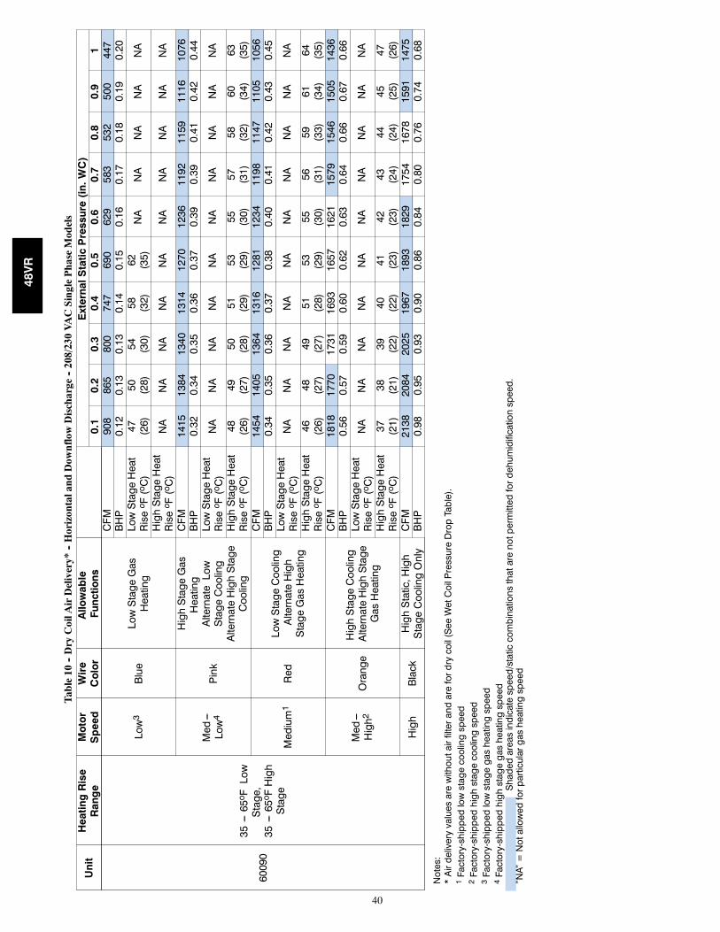
40
Table10
--DryCoilA
irDelivery*
--Horizontaland
Dow
nflowDischarge
--208/230VACSinglePhaseModels
Unit
HeatingRise
Range
Motor
Speed
Wire
Color
Allowable
Functions
ExternalStaticPressure(in.WC)
0.1
0.2
0.3
0.4
0.5
0.6
0.7
0.8
0.9
1
60090
35---65o FLow
Stage,
35---65o FHigh
Stage
Low3
Blue
LowStageGas
Heating
CFM
908
865
800
747
690
629
583
532
500
447
BHP
0.12
0.13
0.13
0.14
0.15
0.16
0.17
0.18
0.19
0.20
LowStageHeat
Riseo F(oC)
47 (26)
50 (28)
54 (30)
58 (32)
62 (35)
NA
NA
NA
NA
NA
HighStageHeat
Riseo F(oC)
NA
NA
NA
NA
NA
NA
NA
NA
NA
NA
Med---
Low4
Pink
HighStageGas
Heating
AlternateLow
StageCooling
AlternateHighStage
Cooling
CFM
1415
1384
1340
1314
1270
1236
1192
1159
1116
1076
BHP
0.32
0.34
0.35
0.36
0.37
0.39
0.39
0.41
0.42
0.44
LowStageHeat
Riseo F(oC)
NA
NA
NA
NA
NA
NA
NA
NA
NA
NA
HighStageHeat
Riseo F(oC)
48 (26)
49 (27)
50 (28)
51 (29)
53 (29)
55 (30)
57 (31)
58 (32)
60 (34)
63 (35)
Medium1
Red
LowStageCooling
AlternateHigh
StageGasHeating
CFM
1454
1405
1364
1316
1281
1234
1198
1147
1105
1056
BHP
0.34
0.35
0.36
0.37
0.38
0.40
0.41
0.42
0.43
0.45
LowStageHeat
Riseo F(oC)
NA
NA
NA
NA
NA
NA
NA
NA
NA
NA
HighStageHeat
Riseo F(oC)
46 (26)
48 (27)
49 (27)
51 (28)
53 (29)
55 (30)
56 (31)
59 (33)
61 (34)
64 (35)
Med---
High2
Orange
HighStageCooling
AlternateHighStage
GasHeating
CFM
1818
1770
1731
1693
1657
1621
1579
1546
1505
1436
BHP
0.56
0.57
0.59
0.60
0.62
0.63
0.64
0.66
0.67
0.66
LowStageHeat
Riseo F(oC)
NA
NA
NA
NA
NA
NA
NA
NA
NA
NA
HighStageHeat
Riseo F(oC)
37 (21)
38 (21)
39 (22)
40 (22)
41 (23)
42 (23)
43 (24)
44 (24)
45 (25)
47 (26)
High
Black
HighStatic,High
StageCoolingOnly
CFM
2138
2084
2025
1967
1893
1829
1754
1678
1591
1475
BHP
0.98
0.95
0.93
0.90
0.86
0.84
0.80
0.76
0.74
0.68
Notes:
*Airdeliveryvaluesarewithoutairfilterandarefordrycoil(SeeWetCoilPressureDropTable).
1Factory-shippedlowstagecoolingspeed
2Factory-shippedhighstagecoolingspeed
3Factory-shippedlowstagegasheatingspeed
4Factory-shippedhighstagegasheatingspeed
Shadedareasindicatespeed/staticcombinationsthatarenotpermittedfordehumidificationspeed.
”NA”=Notallowedforparticulargasheatingspeed
48VR
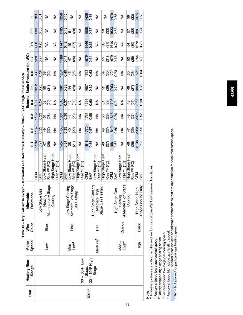
41
Table10
--DryCoilA
irDelivery*
--Horizontaland
Dow
nflowDischarge
--208/230VACSinglePhaseModels
Unit
HeatingRise
Range
Motor
Speed
Wire
Color
Allowable
Functions
ExternalStaticPressure(in.WC)
0.1
0.2
0.3
0.4
0.5
0.6
0.7
0.8
0.9
1
60115
30---60o FLow
Stage,
30---60o FHigh
Stage
Low3
Blue
LowStageGas
Heating
AlternateLowStage
Cooling
CFM
1182
1137
1102
1053
1012
966
920
868
830
783
BHP
0.21
0.22
0.23
0.24
0.25
0.26
0.27
0.28
0.30
0.31
LowStageHeat
Riseo F(oC)
47 (26)
49 (27)
51 (28)
53 (29)
55 (31)
58 (32)
NA
NA
NA
NA
HighStageHeat
Riseo F(oC)
NA
NA
NA
NA
NA
NA
NA
NA
NA
NA
Med---
Low1
Pink
LowStageCooling
AlternateLowStage
GasHeating
CFM
1454
1405
1364
1316
1281
1234
1198
1147
1105
1056
BHP
0.34
0.35
0.36
0.37
0.38
0.40
0.41
0.42
0.43
0.45
LowStageHeat
Riseo F(oC)
38 (21)
40 (22)
41 (23)
42 (24)
44 (24)
45 (25)
47 (26)
49 (27)
51 (28)
NA
HighStageHeat
Riseo F(oC)
NA
NA
NA
NA
NA
NA
NA
NA
NA
NA
Medium2
Red
HighStageCooling
AlternateHigh
StageGasHeating
CFM
1818
1770
1731
1693
1657
1621
1579
1546
1505
1436
BHP
0.56
0.57
0.59
0.60
0.62
0.63
0.64
0.66
0.67
0.66
LowStageHeat
Riseo F(oC)
NA
NA
NA
NA
NA
NA
NA
NA
NA
NA
HighStageHeat
Riseo F(oC)
48 (27)
49 (27)
50 (28)
51 (29)
52 (29)
54 (30)
55 (31)
56 (31)
58 (32)
NA
Med---
High4
Orange
HighStageGas
Heating
AlternateHighStage
Cooling
CFM
1881
1849
1818
1793
1763
1729
1679
1610
1523
1479
BHP
0.67
0.69
0.70
0.71
0.72
0.73
0.73
0.71
0.68
0.65
LowStageHeat
Riseo F(oC)
NA
NA
NA
NA
NA
NA
NA
NA
NA
NA
HighStageHeat
Riseo F(oC)
46 (26)
47 (26)
48 (27)
48 (27)
49 (27)
50 (28)
52 (29)
54 (30)
57 (32)
59 (33)
High
Black
HighStatic,High
StageCoolingOnly
CFM
2138
2084
2025
1967
1893
1829
1754
1678
1591
1475
BHP
0.98
0.95
0.93
0.90
0.86
0.84
0.80
0.76
0.74
0.68
Notes:
*Airdeliveryvaluesarewithoutairfilterandarefordrycoil(SeeWetCoilPressureDropTable).
1Factory-shippedlowstagecoolingspeed
2Factory-shippedhighstagecoolingspeed
3Factory-shippedlowstagegasheatingspeed
4Factory-shippedhighstagegasheatingspeed
Shadedareasindicatespeed/staticcombinationsthatarenotpermittedfordehumidificationspeed.
”NA”=Notallowedforparticulargasheatingspeed
48VR
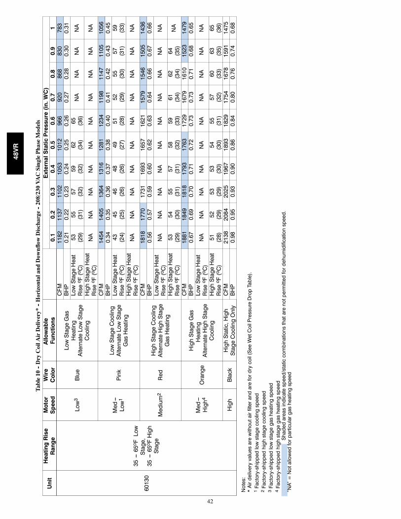
42
Table10
--DryCoilA
irDelivery*
--Horizontaland
Dow
nflowDischarge
--208/230VACSinglePhaseModels
Unit
HeatingRise
Range
Motor
Speed
Wire
Color
Allowable
Functions
ExternalStaticPressure(in.WC)
0.1
0.2
0.3
0.4
0.5
0.6
0.7
0.8
0.9
1
60130
35---65o FLow
Stage,
35---65o FHigh
Stage
Low3
Blue
LowStageGas
Heating
AlternateLowStage
Cooling
CFM
1182
1137
1102
1053
1012
966
920
868
830
783
BHP
0.21
0.22
0.23
0.24
0.25
0.26
0.27
0.28
0.30
0.31
LowStageHeat
Riseo F(oC)
53 (29)
55 (31)
57 (32)
59 (32)
62 (34)
65 (36)
NA
NA
NA
NA
HighStageHeat
Riseo F(oC)
NA
NA
NA
NA
NA
NA
NA
NA
NA
NA
Med---
Low1
Pink
LowStageCooling
AlternateLowStage
GasHeating
CFM
1454
1405
1364
1316
1281
1234
1198
1147
1105
1056
BHP
0.34
0.35
0.36
0.37
0.38
0.40
0.41
0.42
0.43
0.45
LowStageHeat
Riseo F(oC)
43 (24)
45 (25)
46 (26)
48 (26)
49 (27)
51 (28)
52 (29)
55 (30)
57 (31)
59 (33)
HighStageHeat
Riseo F(oC)
NA
NA
NA
NA
NA
NA
NA
NA
NA
NA
Medium2
Red
HighStageCooling
AlternateHighStage
GasHeating
CFM
1818
1770
1731
1693
1657
1621
1579
1546
1505
1436
BHP
0.56
0.57
0.59
0.60
0.62
0.63
0.64
0.66
0.67
0.66
LowStageHeat
Riseo F(oC)
NA
NA
NA
NA
NA
NA
NA
NA
NA
NA
HighStageHeat
Riseo F(oC)
53 (29)
54 (30)
55 (31)
57 (31)
58 (32)
59 (33)
61 (34)
62 (34)
64 (35)
NA
Med---
High4
Orange
HighStageGas
Heating
AlternateHighStage
Cooling
CFM
1881
1849
1818
1793
1763
1729
1679
1610
1523
1479
BHP
0.67
0.69
0.70
0.71
0.72
0.73
0.73
0.71
0.68
0.65
LowStageHeat
Riseo F(oC)
NA
NA
NA
NA
NA
NA
NA
NA
NA
NA
HighStageHeat
Riseo F(oC)
51 (28)
52 (29)
53 (29)
53 (30)
54 (30)
55 (31)
57 (32)
60 (33)
63 (35)
65 (36)
High
Black
HighStatic,High
StageCoolingOnly
CFM
2138
2084
2025
1967
1893
1829
1754
1678
1591
1475
BHP
0.98
0.95
0.93
0.90
0.86
0.84
0.80
0.76
0.74
0.68
Notes:
*Airdeliveryvaluesarewithoutairfilterandarefordrycoil(SeeWetCoilPressureDropTable).
1Factory-shippedlowstagecoolingspeed
2Factory-shippedhighstagecoolingspeed
3Factory-shippedlowstagegasheatingspeed
4Factory-shippedhighstagegasheatingspeed
Shadedareasindicatespeed/staticcombinationsthatarenotpermittedfordehumidificationspeed.
”NA”=Notallowedforparticulargasheatingspeed
48VR
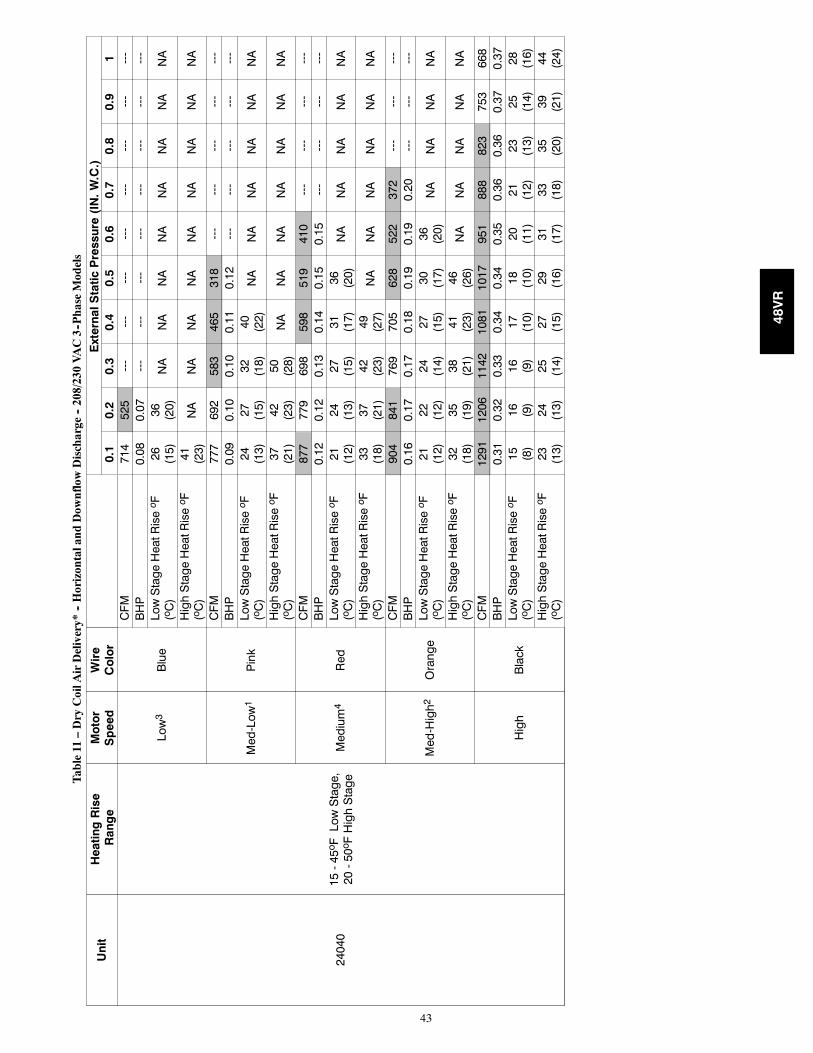
43
Table11
–DryCoilA
irDelivery*
--Horizontaland
Dow
nflowDischarge
--208/230VAC3--PhaseModels
Unit
HeatingRise
Range
Motor
Speed
Wire
Color
ExternalStaticPressure(IN.W.C.)
0.1
0.2
0.3
0.4
0.5
0.6
0.7
0.8
0.9
1
24040
15-45oFLowStage,
20-50oFHighStage
Low3
Blue
CFM
714
525
---
---
---
---
---
---
---
---
BHP
0.08
0.07
---
---
---
---
---
---
---
---
LowStageHeatRiseo F
(oC)
26 (15)
36 (20)
NA
NA
NA
NA
NA
NA
NA
NA
HighStageHeatRiseo F
(oC)
41 (23)
NA
NA
NA
NA
NA
NA
NA
NA
NA
Med-Low1
Pink
CFM
777
692
583
465
318
---
---
---
---
---
BHP
0.09
0.10
0.10
0.11
0.12
---
---
---
---
---
LowStageHeatRiseo F
(oC)
24 (13)
27 (15)
32 (18)
40 (22)
NA
NA
NA
NA
NA
NA
HighStageHeatRiseo F
(oC)
37 (21)
42 (23)
50 (28)
NA
NA
NA
NA
NA
NA
NA
Medium4
Red
CFM
877
779
698
598
519
410
---
---
---
---
BHP
0.12
0.12
0.13
0.14
0.15
0.15
---
---
---
---
LowStageHeatRiseo F
(oC)
21 (12)
24 (13)
27 (15)
31 (17)
36 (20)
NA
NA
NA
NA
NA
HighStageHeatRiseo F
(oC)
33 (18)
37 (21)
42 (23)
49 (27)
NA
NA
NA
NA
NA
NA
Med-High2
Orange
CFM
904
841
769
705
628
522
372
---
---
---
BHP
0.16
0.17
0.17
0.18
0.19
0.19
0.20
---
---
---
LowStageHeatRiseo F
(oC)
21 (12)
22 (12)
24 (14)
27 (15)
30 (17)
36 (20)
NA
NA
NA
NA
HighStageHeatRiseo F
(oC)
32 (18)
35 (19)
38 (21)
41 (23)
46 (26)
NA
NA
NA
NA
NA
High
Black
CFM
1291
1206
1142
1081
1017
951
888
823
753
668
BHP
0.31
0.32
0.33
0.34
0.34
0.35
0.36
0.36
0.37
0.37
LowStageHeatRiseo F
(oC)
15 (8)
16 (9)
16 (9)
17 (10)
18 (10)
20 (11)
21 (12)
23 (13)
25 (14)
28 (16)
HighStageHeatRiseo F
(oC)
23 (13)
24 (13)
25 (14)
27 (15)
29 (16)
31 (17)
33 (18)
35 (20)
39 (21)
44 (24)
48VR
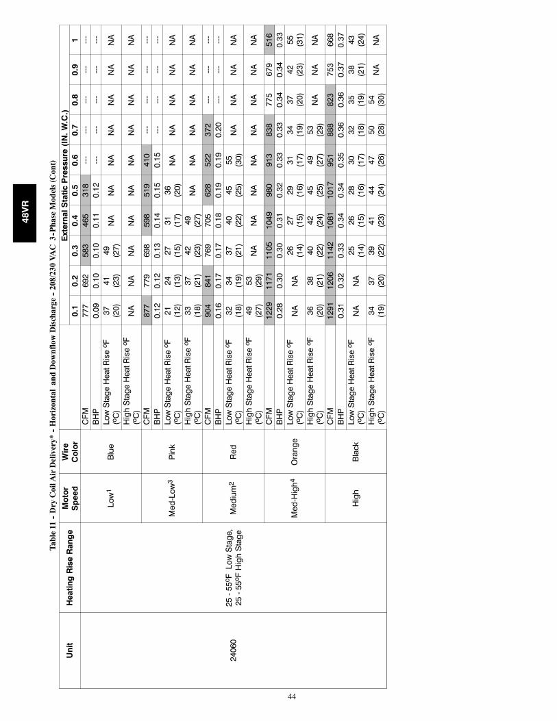
44
Table11
--DryCoilA
irDelivery*
--HorizontalandDow
nflowDischarge
--208/230VAC
3--PhaseModels(Cont)
Unit
HeatingRiseRange
Motor
Speed
Wire
Color
ExternalStaticPressure(IN.W.C.)
0.1
0.2
0.3
0.4
0.5
0.6
0.7
0.8
0.9
1
24060
25-55oFLowStage,
25-55oFHighStage
Low1
Blue
CFM
777
692
583
465
318
---
---
---
---
---
BHP
0.09
0.10
0.10
0.11
0.12
---
---
---
---
---
LowStageHeatRiseo F
(oC)
37 (20)
41 (23)
49 (27)
NA
NA
NA
NA
NA
NA
NA
HighStageHeatRiseo F
(oC)
NA
NA
NA
NA
NA
NA
NA
NA
NA
NA
Med-Low3
Pink
CFM
877
779
698
598
519
410
---
---
---
---
BHP
0.12
0.12
0.13
0.14
0.15
0.15
---
---
---
---
LowStageHeatRiseo F
(oC)
21 (12)
24 (13)
27 (15)
31 (17)
36 (20)
NA
NA
NA
NA
NA
HighStageHeatRiseo F
(oC)
33 (18)
37 (21)
42 (23)
49 (27)
NA
NA
NA
NA
NA
NA
Medium2
Red
CFM
904
841
769
705
628
522
372
---
---
---
BHP
0.16
0.17
0.17
0.18
0.19
0.19
0.20
---
---
---
LowStageHeatRiseo F
(oC)
32 (18)
34 (19)
37 (21)
40 (22)
45 (25)
55 (30)
NA
NA
NA
NA
HighStageHeatRiseo F
(oC)
49 (27)
53 (29)
NA
NA
NA
NA
NA
NA
NA
NA
Med-High4
Orange
CFM
1229
1171
1105
1049
980
913
838
775
679
516
BHP
0.28
0.30
0.30
0.31
0.32
0.33
0.33
0.34
0.34
0.33
LowStageHeatRiseo F
(oC)
NA
NA
26 (14)
27 (15)
29 (16)
31 (17)
34 (19)
37 (20)
42 (23)
55 (31)
HighStageHeatRiseo F
(oC)
36 (20)
38 (21)
40 (22)
42 (24)
45 (25)
49 (27)
53 (29)
NA
NA
NA
High
Black
CFM
1291
1206
1142
1081
1017
951
888
823
753
668
BHP
0.31
0.32
0.33
0.34
0.34
0.35
0.36
0.36
0.37
0.37
LowStageHeatRiseo F
(oC)
NA
NA
25 (14)
26 (15)
28 (16)
30 (17)
32 (18)
35 (19)
38 (21)
43 (24)
HighStageHeatRiseo F
(oC)
34 (19)
37 (20)
39 (22)
41 (23)
44 (24)
47 (26)
50 (28)
54 (30)
NA
NA
48VR
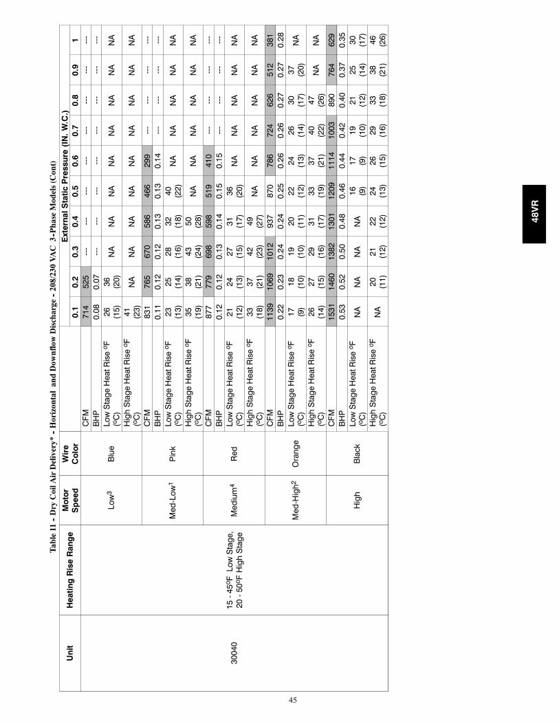
45
Table11
--DryCoilA
irDelivery*
--HorizontalandDow
nflowDischarge
--208/230VAC
3--PhaseModels(Cont)
Unit
HeatingRiseRange
Motor
Speed
Wire
Color
ExternalStaticPressure(IN.W.C.)
0.1
0.2
0.3
0.4
0.5
0.6
0.7
0.8
0.9
1
30040
15-45oFLowStage,
20-50oFHighStage
Low3
Blue
CFM
714
525
---
---
---
---
---
---
---
---
BHP
0.08
0.07
---
---
---
---
---
---
---
---
LowStageHeatRiseo F
(oC)
26 (15)
36 (20)
NA
NA
NA
NA
NA
NA
NA
NA
HighStageHeatRiseo F
(oC)
41 (23)
NA
NA
NA
NA
NA
NA
NA
NA
NA
Med-Low1
Pink
CFM
831
765
670
586
466
299
---
---
---
---
BHP
0.11
0.12
0.12
0.13
0.13
0.14
---
---
---
---
LowStageHeatRiseo F
(oC)
23 (13)
25 (14)
28 (16)
32 (18)
40 (22)
NA
NA
NA
NA
NA
HighStageHeatRiseo F
(oC)
35 (19)
38 (21)
43 (24)
50 (28)
NA
NA
NA
NA
NA
NA
Medium4
Red
CFM
877
779
698
598
519
410
---
---
---
---
BHP
0.12
0.12
0.13
0.14
0.15
0.15
---
---
---
---
LowStageHeatRiseo F
(oC)
21 (12)
24 (13)
27 (15)
31 (17)
36 (20)
NA
NA
NA
NA
NA
HighStageHeatRiseo F
(oC)
33 (18)
37 (21)
42 (23)
49 (27)
NA
NA
NA
NA
NA
NA
Med-High2
Orange
CFM
1139
1069
1012
937
870
786
724
626
512
381
BHP
0.22
0.23
0.24
0.24
0.25
0.26
0.26
0.27
0.27
0.28
LowStageHeatRiseo F
(oC)
17 (9)
18 (10)
19 (10)
20 (11)
22 (12)
24 (13)
26 (14)
30 (17)
37 (20)
NA
HighStageHeatRiseo F
(oC)
26 (14)
27 (15)
29 (16)
31 (17)
33 (19)
37 (21)
40 (22)
47 (26)
NA
NA
High
Black
CFM
1531
1460
1382
1301
1209
1114
1003
890
764
629
BHP
0.53
0.52
0.50
0.48
0.46
0.44
0.42
0.40
0.37
0.35
LowStageHeatRiseo F
(oC)
NA
NA
NA
NA
16 (9)
17 (9)
19 (10)
21 (12)
25 (14)
30 (17)
HighStageHeatRiseo F
(oC)
NA
20 (11)
21 (12)
22 (12)
24 (13)
26 (15)
29 (16)
33 (18)
38 (21)
46 (26)
48VR
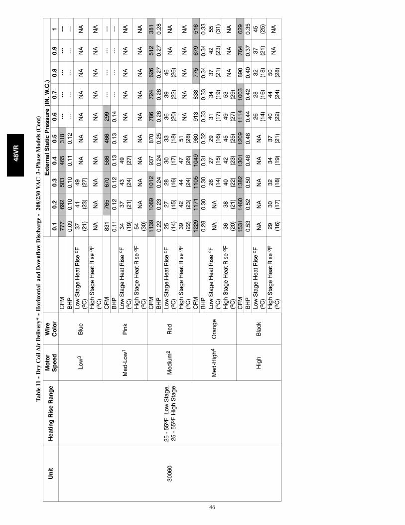
46
Table11
--DryCoilA
irDelivery*
--HorizontalandDow
nflowDischarge
--208/230VAC
3--PhaseModels(Cont)
Unit
HeatingRiseRange
Motor
Speed
Wire
Color
ExternalStaticPressure(IN.W.C.)
0.1
0.2
0.3
0.4
0.5
0.6
0.7
0.8
0.9
1
30060
25-55oFLowStage,
25-55oFHighStage
Low3
Blue
CFM
777
692
583
465
318
---
---
---
---
---
BHP
0.09
0.10
0.10
0.11
0.12
---
---
---
---
---
LowStageHeatRiseo F
(oC)
37 (21)
41 (23)
49 (27)
NA
NA
NA
NA
NA
NA
NA
HighStageHeatRiseo F
(oC)
NA
NA
NA
NA
NA
NA
NA
NA
NA
NA
Med-Low1
Pink
CFM
831
765
670
586
466
299
---
---
---
---
BHP
0.11
0.12
0.12
0.13
0.13
0.14
---
---
---
---
LowStageHeatRiseo F
(oC)
34 (19)
37 (21)
43 (24)
49 (27)
NA
NA
NA
NA
NA
NA
HighStageHeatRiseo F
(oC)
54 (30)
NA
NA
NA
NA
NA
NA
NA
NA
NA
Medium2
Red
CFM
1139
1069
1012
937
870
786
724
626
512
381
BHP
0.22
0.23
0.24
0.24
0.25
0.26
0.26
0.27
0.27
0.28
LowStageHeatRiseo F
(oC)
25 (14)
27 (15)
28 (16)
30 (17)
33 (18)
36 (20)
39 (22)
46 (26)
NA
NA
HighStageHeatRiseo F
(oC)
39 (22)
42 (23)
44 (24)
47 (26)
51 (28)
NA
NA
NA
NA
NA
Med-High4
Orange
CFM
1229
1171
1105
1049
980
913
838
775
679
516
BHP
0.28
0.30
0.30
0.31
0.32
0.33
0.33
0.34
0.34
0.33
LowStageHeatRiseo F
(oC)
NA
NA
26 (14)
27 (15)
29 (16)
31 (17)
34 (19)
37 (21)
42 (23)
55 (31)
HighStageHeatRiseo F
(oC)
36 (20)
38 (21)
40 (22)
42 (23)
45 (25)
49 (27)
53 (29)
NA
NA
NA
High
Black
CFM
1531
1460
1382
1301
1209
1114
1003
890
764
629
BHP
0.53
0.52
0.50
0.48
0.46
0.44
0.42
0.40
0.37
0.35
LowStageHeatRiseo F
(oC)
NA
NA
NA
NA
NA
26 (14)
28 (16)
32 (18)
37 (21)
45 (25)
HighStageHeatRiseo F
(oC)
29 (16)
30 (17)
32 (18)
34 (19)
37 (21)
40 (22)
44 (24)
50 (28)
NA
NA
48VR
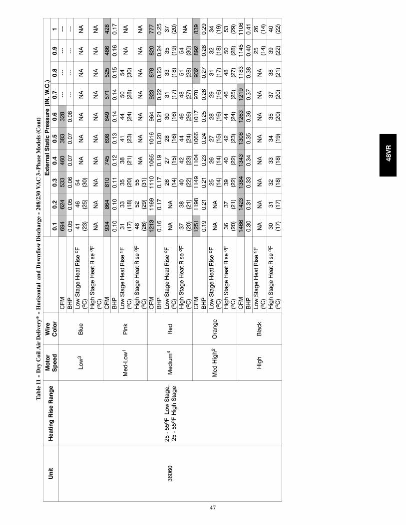
47
Table11
--DryCoilA
irDelivery*
--HorizontalandDow
nflowDischarge
--208/230VAC3--PhaseModels(Cont)
Unit
HeatingRiseRange
Motor
Speed
Wire
Color
ExternalStaticPressure(IN.W.C.)
0.1
0.2
0.3
0.4
0.5
0.6
0.7
0.8
0.9
1
36060
25-55oFLowStage,
25-55oFHighStage
Low3
Blue
CFM
694
624
533
460
383
328
---
---
---
---
BHP
0.05
0.05
0.06
0.07
0.07
0.08
---
---
---
---
LowStageHeatRiseo F
(oC)
41 (23)
46 (25)
54 (30)
NA
NA
NA
NA
NA
NA
NA
HighStageHeatRiseo F
(oC)
NA
NA
NA
NA
NA
NA
NA
NA
NA
NA
Med-Low1
Pink
CFM
934
864
810
745
698
649
571
525
486
428
BHP
0.10
0.10
0.11
0.12
0.13
0.14
0.14
0.15
0.16
0.17
LowStageHeatRiseo F
(oC)
31 (17)
33 (18)
35 (20)
38 (21)
41 (23)
44 (24)
50 (28)
54 (30)
NA
NA
HighStageHeatRiseo F
(oC)
48 (26)
52 (29)
55 (31)
NA
NA
NA
NA
NA
NA
NA
Medium4
Red
CFM
1213
1169
1110
1065
1016
964
923
878
820
777
BHP
0.16
0.17
0.17
0.19
0.20
0.21
0.22
0.23
0.24
0.25
LowStageHeatRiseo F
(oC)
NA
NA
26 (14)
27 (15)
28 (16)
30 (16)
31 (17)
33 (18)
35 (19)
37 (20)
HighStageHeatRiseo F
(oC)
37 (20)
38 (21)
40 (22)
42 (23)
44 (24)
46 (26)
48 (27)
51 (28)
54 (30)
NA
Med-High2
Orange
CFM
1251
1198
1149
1104
1066
1017
970
932
892
839
BHP
0.19
0.21
0.21
0.23
0.24
0.25
0.26
0.27
0.28
0.29
LowStageHeatRiseo F
(oC)
NA
NA
25 (14)
26 (14)
27 (15)
28 (16)
29 (16)
31 (17)
32 (18)
34 (19)
HighStageHeatRiseo F
(oC)
36 (20)
37 (21)
39 (22)
40 (22)
42 (23)
44 (24)
46 (25)
48 (27)
50 (28)
53 (29)
High
Black
CFM
1466
1423
1384
1343
1308
1263
1219
1183
1145
1106
BHP
0.30
0.31
0.33
0.34
0.35
0.36
0.37
0.38
0.40
0.41
LowStageHeatRiseo F
(oC)
NA
NA
NA
NA
NA
NA
NA
NA
25 (14)
26 (14)
HighStageHeatRiseo F
(oC)
30 (17)
31 (17)
32 (18)
33 (18)
34 (19)
35 (20)
37 (20)
38 (21)
39 (22)
40 (22)
48VR
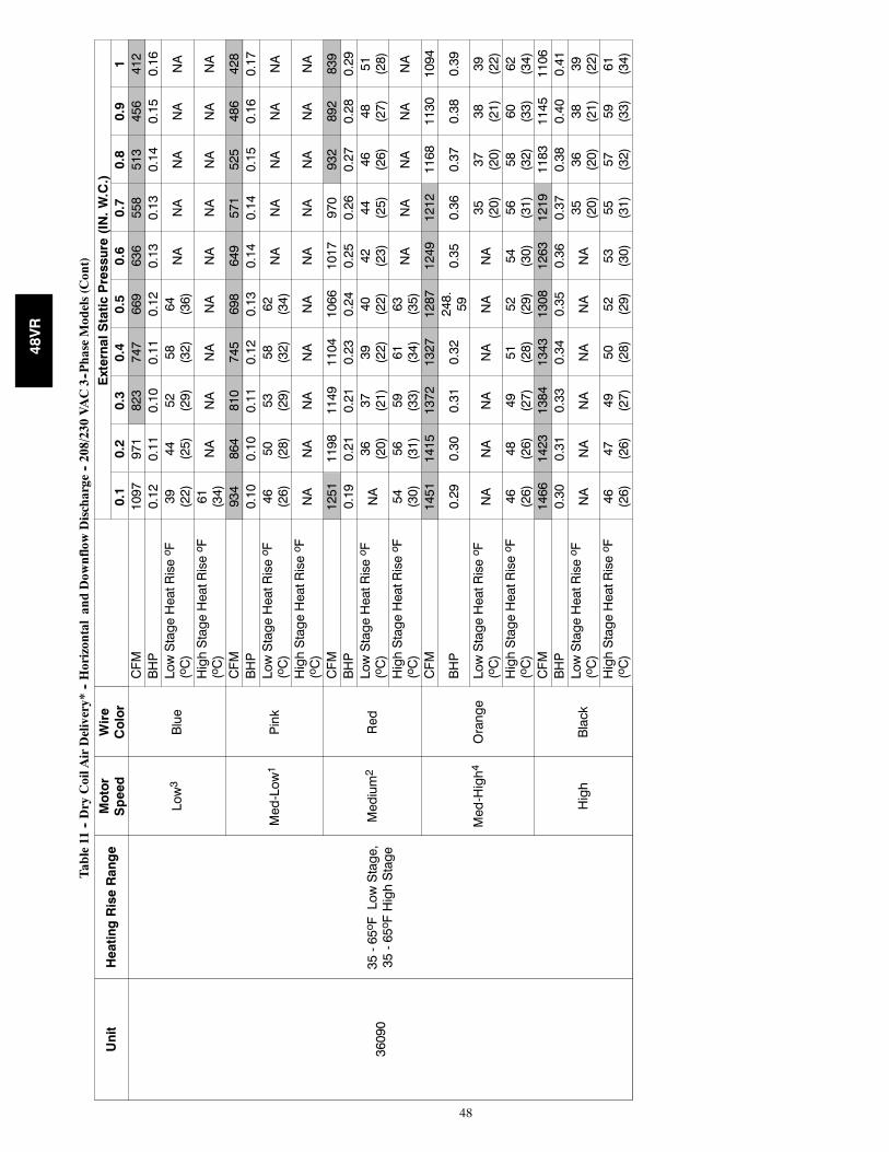
48
Table11
--DryCoilA
irDelivery*
--HorizontalandDow
nflowDischarge
--208/230VAC3--PhaseModels(Cont)
Unit
HeatingRiseRange
Motor
Speed
Wire
Color
ExternalStaticPressure(IN.W.C.)
0.1
0.2
0.3
0.4
0.5
0.6
0.7
0.8
0.9
1
36090
35-65oFLowStage,
35-65oFHighStage
Low3
Blue
CFM
1097
971
823
747
669
636
558
513
456
412
BHP
0.12
0.11
0.10
0.11
0.12
0.13
0.13
0.14
0.15
0.16
LowStageHeatRiseo F
(oC)
39 (22)
44 (25)
52 (29)
58 (32)
64 (36)
NA
NA
NA
NA
NA
HighStageHeatRiseo F
(oC)
61 (34)
NA
NA
NA
NA
NA
NA
NA
NA
NA
Med-Low1
Pink
CFM
934
864
810
745
698
649
571
525
486
428
BHP
0.10
0.10
0.11
0.12
0.13
0.14
0.14
0.15
0.16
0.17
LowStageHeatRiseo F
(oC)
46 (26)
50 (28)
53 (29)
58 (32)
62 (34)
NA
NA
NA
NA
NA
HighStageHeatRiseo F
(oC)
NA
NA
NA
NA
NA
NA
NA
NA
NA
NA
Medium2
Red
CFM
1251
1198
1149
1104
1066
1017
970
932
892
839
BHP
0.19
0.21
0.21
0.23
0.24
0.25
0.26
0.27
0.28
0.29
LowStageHeatRiseo F
(oC)
NA
36 (20)
37 (21)
39 (22)
40 (22)
42 (23)
44 (25)
46 (26)
48 (27)
51 (28)
HighStageHeatRiseo F
(oC)
54 (30)
56 (31)
59 (33)
61 (34)
63 (35)
NA
NA
NA
NA
NA
Med-High4
Orange
CFM
1451
1415
1372
1327
1287
1249
1212
1168
1130
1094
BHP
0.29
0.30
0.31
0.32
248.59
0.35
0.36
0.37
0.38
0.39
LowStageHeatRiseo F
(oC)
NA
NA
NA
NA
NA
NA
35 (20)
37 (20)
38 (21)
39 (22)
HighStageHeatRiseo F
(oC)
46 (26)
48 (26)
49 (27)
51 (28)
52 (29)
54 (30)
56 (31)
58 (32)
60 (33)
62 (34)
High
Black
CFM
1466
1423
1384
1343
1308
1263
1219
1183
1145
1106
BHP
0.30
0.31
0.33
0.34
0.35
0.36
0.37
0.38
0.40
0.41
LowStageHeatRiseo F
(oC)
NA
NA
NA
NA
NA
NA
35 (20)
36 (20)
38 (21)
39 (22)
HighStageHeatRiseo F
(oC)
46 (26)
47 (26)
49 (27)
50 (28)
52 (29)
53 (30)
55 (31)
57 (32)
59 (33)
61 (34)
48VR
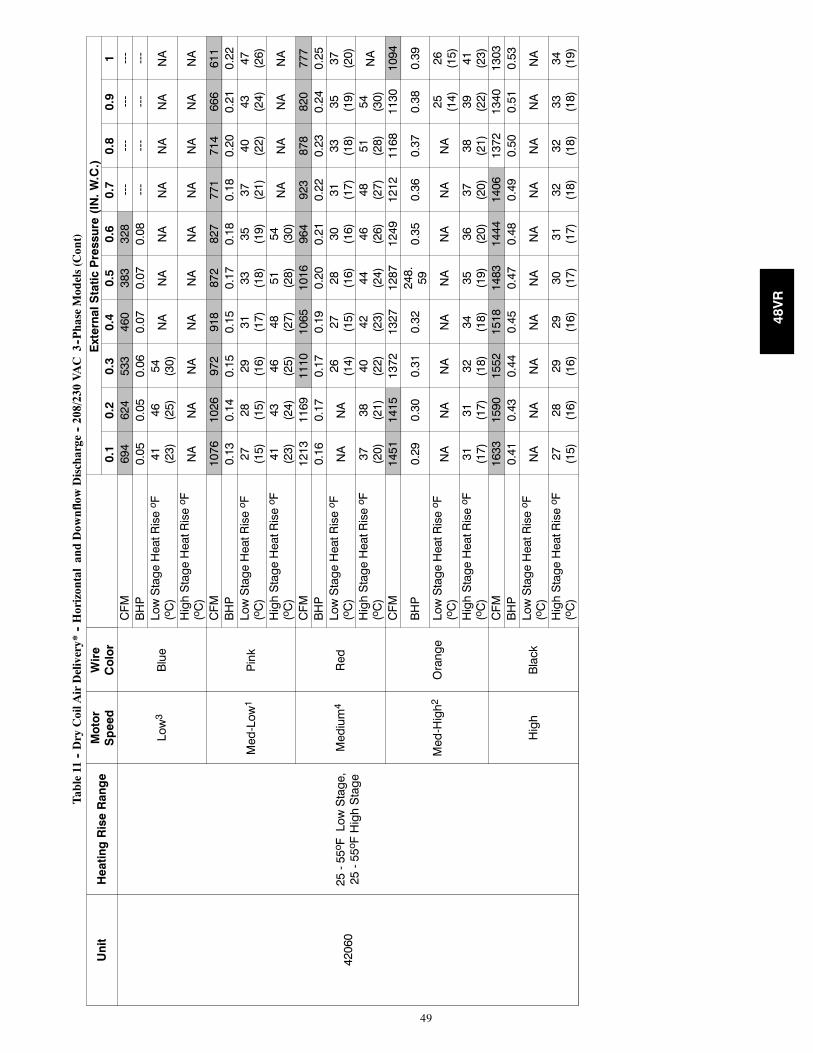
49
Table11
--DryCoilA
irDelivery*
--HorizontalandDow
nflowDischarge
--208/230VAC
3--PhaseModels(Cont)
Unit
HeatingRiseRange
Motor
Speed
Wire
Color
ExternalStaticPressure(IN.W.C.)
0.1
0.2
0.3
0.4
0.5
0.6
0.7
0.8
0.9
1
42060
25-55oFLowStage,
25-55oFHighStage
Low3
Blue
CFM
694
624
533
460
383
328
---
---
---
---
BHP
0.05
0.05
0.06
0.07
0.07
0.08
---
---
---
---
LowStageHeatRiseo F
(oC)
41 (23)
46 (25)
54 (30)
NA
NA
NA
NA
NA
NA
NA
HighStageHeatRiseo F
(oC)
NA
NA
NA
NA
NA
NA
NA
NA
NA
NA
Med-Low1
Pink
CFM
1076
1026
972
918
872
827
771
714
666
611
BHP
0.13
0.14
0.15
0.15
0.17
0.18
0.18
0.20
0.21
0.22
LowStageHeatRiseo F
(oC)
27 (15)
28 (15)
29 (16)
31 (17)
33 (18)
35 (19)
37 (21)
40 (22)
43 (24)
47 (26)
HighStageHeatRiseo F
(oC)
41 (23)
43 (24)
46 (25)
48 (27)
51 (28)
54 (30)
NA
NA
NA
NA
Medium4
Red
CFM
1213
1169
1110
1065
1016
964
923
878
820
777
BHP
0.16
0.17
0.17
0.19
0.20
0.21
0.22
0.23
0.24
0.25
LowStageHeatRiseo F
(oC)
NA
NA
26 (14)
27 (15)
28 (16)
30 (16)
31 (17)
33 (18)
35 (19)
37 (20)
HighStageHeatRiseo F
(oC)
37 (20)
38 (21)
40 (22)
42 (23)
44 (24)
46 (26)
48 (27)
51 (28)
54 (30)
NA
Med-High2
Orange
CFM
1451
1415
1372
1327
1287
1249
1212
1168
1130
1094
BHP
0.29
0.30
0.31
0.32
248.59
0.35
0.36
0.37
0.38
0.39
LowStageHeatRiseo F
(oC)
NA
NA
NA
NA
NA
NA
NA
NA
25 (14)
26 (15)
HighStageHeatRiseo F
(oC)
31 (17)
31 (17)
32 (18)
34 (18)
35 (19)
36 (20)
37 (20)
38 (21)
39 (22)
41 (23)
High
Black
CFM
1633
1590
1552
1518
1483
1444
1406
1372
1340
1303
BHP
0.41
0.43
0.44
0.45
0.47
0.48
0.49
0.50
0.51
0.53
LowStageHeatRiseo F
(oC)
NA
NA
NA
NA
NA
NA
NA
NA
NA
NA
HighStageHeatRiseo F
(oC)
27 (15)
28 (16)
29 (16)
29 (16)
30 (17)
31 (17)
32 (18)
32 (18)
33 (18)
34 (19)
48VR
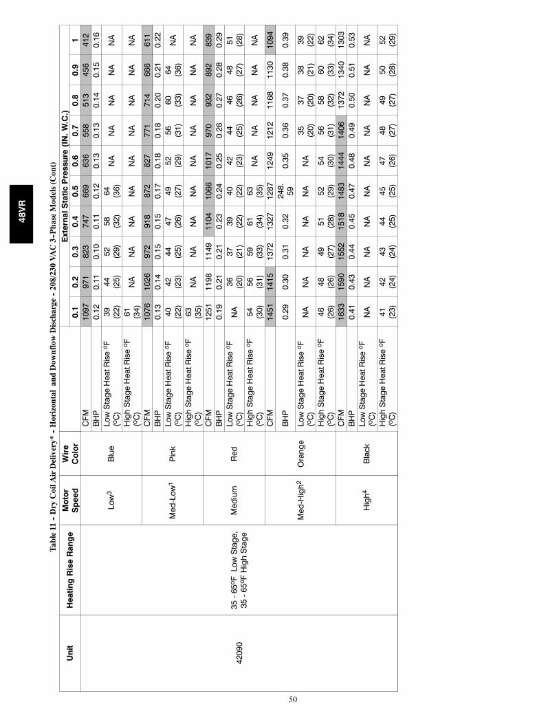
50
Table11
--DryCoilA
irDelivery*
--HorizontalandDow
nflowDischarge
--208/230VAC3--PhaseModels(Cont)
Unit
HeatingRiseRange
Motor
Speed
Wire
Color
ExternalStaticPressure(IN.W.C.)
0.1
0.2
0.3
0.4
0.5
0.6
0.7
0.8
0.9
1
42090
35-65oFLowStage,
35-65oFHighStage
Low3
Blue
CFM
1097
971
823
747
669
636
558
513
456
412
BHP
0.12
0.11
0.10
0.11
0.12
0.13
0.13
0.14
0.15
0.16
LowStageHeatRiseo F
(oC)
39 (22)
44 (25)
52 (29)
58 (32)
64 (36)
NA
NA
NA
NA
NA
HighStageHeatRiseo F
(oC)
61 (34)
NA
NA
NA
NA
NA
NA
NA
NA
NA
Med-Low1
Pink
CFM
1076
1026
972
918
872
827
771
714
666
611
BHP
0.13
0.14
0.15
0.15
0.17
0.18
0.18
0.20
0.21
0.22
LowStageHeatRiseo F
(oC)
40 (22)
42 (23)
44 (25)
47 (26)
49 (27)
52 (29)
56 (31)
60 (33)
64 (36)
NA
HighStageHeatRiseo F
(oC)
63 (35)
NA
NA
NA
NA
NA
NA
NA
NA
NA
Medium
Red
CFM
1251
1198
1149
1104
1066
1017
970
932
892
839
BHP
0.19
0.21
0.21
0.23
0.24
0.25
0.26
0.27
0.28
0.29
LowStageHeatRiseo F
(oC)
NA
36 (20)
37 (21)
39 (22)
40 (22)
42 (23)
44 (25)
46 (26)
48 (27)
51 (28)
HighStageHeatRiseo F
(oC)
54 (30)
56 (31)
59 (33)
61 (34)
63 (35)
NA
NA
NA
NA
NA
Med-High2
Orange
CFM
1451
1415
1372
1327
1287
1249
1212
1168
1130
1094
BHP
0.29
0.30
0.31
0.32
248.59
0.35
0.36
0.37
0.38
0.39
LowStageHeatRiseo F
(oC)
NA
NA
NA
NA
NA
NA
35 (20)
37 (20)
38 (21)
39 (22)
HighStageHeatRiseo F
(oC)
46 (26)
48 (26)
49 (27)
51 (28)
52 (29)
54 (30)
56 (31)
58 (32)
60 (33)
62 (34)
High4
Black
CFM
1633
1590
1552
1518
1483
1444
1406
1372
1340
1303
BHP
0.41
0.43
0.44
0.45
0.47
0.48
0.49
0.50
0.51
0.53
LowStageHeatRiseo F
(oC)
NA
NA
NA
NA
NA
NA
NA
NA
NA
NA
HighStageHeatRiseo F
(oC)
41 (23)
42 (24)
43 (24)
44 (25)
45 (25)
47 (26)
48 (27)
49 (27)
50 (28)
52 (29)
48VR
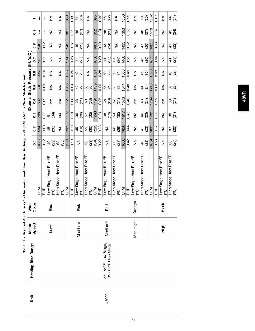
51
Table11
--DryCoilA
irDelivery*
--HorizontalandDow
nflowDischarge
--208/230VAC
3--PhaseModels(Cont)
Unit
HeatingRiseRange
Motor
Speed
Wire
Color
ExternalStaticPressure(IN.W.C.)
0.1
0.2
0.3
0.4
0.5
0.6
0.7
0.8
0.9
1
48090
35-65oFLowStage,
35-65oFHighStage
Low3
Blue
CFM
1067
904
703
587
501
449
380
340
---
---
BHP
0.12
0.10
0.09
0.09
0.09
0.10
0.11
0.12
---
---
LowStageHeatRiseo F
(oC)
40 (22)
48 (26)
61 (34)
NA
NA
NA
NA
NA
NA
NA
HighStageHeatRiseo F
(oC)
63 (35)
NA
NA
NA
NA
NA
NA
NA
NA
NA
Med-Low1
Pink
CFM
1271
1229
1177
1121
1066
1027
974
942
887
839
BHP
0.19
0.20
0.21
0.23
0.24
0.25
0.26
0.27
0.28
0.29
LowStageHeatRiseo F
(oC)
NA
35 (19)
36 (20)
38 (21)
40 (22)
42 (23)
44 (25)
46 (25)
48 (27)
51 (28)
HighStageHeatRiseo F
(oC)
53 (29)
55 (30)
57 (32)
60 (33)
63 (35)
NA
NA
NA
NA
NA
Medium4
Red
CFM
1340
1299
1240
1191
1139
1091
1050
1001
952
895
BHP
0.22
0.23
0.24
0.25
0.26
0.28
0.29
0.30
0.31
0.32
LowStageHeatRiseo F
(oC)
NA
NA
35 (19)
36 (20)
38 (21)
39 (22)
41 (23)
43 (24)
45 (25)
48 (27)
HighStageHeatRiseo F
(oC)
50 (28)
52 (29)
54 (30)
57 (31)
59 (33)
62 (34)
64 (36)
NA
NA
NA
Med-High2
Orange
CFM
1686
1650
1617
1576
1544
1503
1468
1433
1393
1356
BHP
0.42
0.44
0.45
0.46
0.48
0.49
0.51
0.52
0.53
0.55
LowStageHeatRiseo F
(oC)
NA
NA
NA
NA
NA
NA
NA
NA
NA
NA
HighStageHeatRiseo F
(oC)
40 (22)
41 (23)
42 (23)
43 (24)
44 (24)
45 (25)
46 (26)
47 (26)
48 (27)
50 (28)
High
Black
CFM
1854
1837
1781
1784
1720
1698
1655
1625
1578
1532
BHP
0.56
0.57
0.60
0.59
0.62
0.63
0.64
0.66
0.67
0.67
LowStageHeatRiseo F
(oC)
NA
NA
NA
NA
NA
NA
NA
NA
NA
NA
HighStageHeatRiseo F
(oC)
36 (20)
37 (20)
38 (21)
38 (21)
39 (22)
40 (22)
41 (23)
41 (23)
43 (24)
44 (24)
48VR
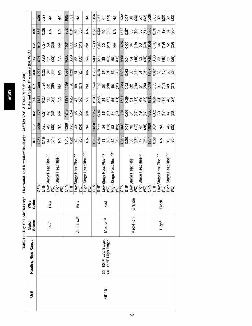
52
Table11
--DryCoilA
irDelivery*
--HorizontalandDow
nflowDischarge
--208/230VAC
3--PhaseModels(Cont)
Unit
HeatingRiseRange
Motor
Speed
Wire
Color
ExternalStaticPressure(IN.W.C.)
0.1
0.2
0.3
0.4
0.5
0.6
0.7
0.8
0.9
1
48115
30-60oFLowStage,
30-60oFHighStage
Low1
Blue
CFM
1271
1229
1177
1121
1066
1027
974
942
887
839
BHP
0.19
0.20
0.21
0.23
0.24
0.25
0.26
0.27
0.28
0.29
LowStageHeatRiseo F
(oC)
44 (24)
45 (25)
47 (26)
50 (28)
52 (29)
54 (30)
57 (32)
59 (33)
NA
NA
HighStageHeatRiseo F
(oC)
NA
NA
NA
NA
NA
NA
NA
NA
NA
NA
Med-Low3
Pink
CFM
1340
1299
1240
1191
1139
1091
1050
1001
952
895
BHP
0.22
0.23
0.24
0.25
0.26
0.28
0.29
0.30
0.31
0.32
LowStageHeatRiseo F
(oC)
42 (23)
43 (24)
45 (25)
47 (26)
49 (27)
51 (28)
53 (30)
56 (31)
59 (33)
NA
HighStageHeatRiseo F
(oC)
NA
NA
NA
NA
NA
NA
NA
NA
NA
NA
Medium2
Red
CFM
1686
1650
1617
1576
1544
1503
1468
1433
1393
1356
BHP
0.42
0.44
0.45
0.46
0.48
0.49
0.51
0.52
0.53
0.55
LowStageHeatRiseo F
(oC)
33 (18)
34 (19)
35 (19)
35 (20)
36 (20)
37 (21)
38 (21)
39 (22)
40 (22)
41 (23)
HighStageHeatRiseo F
(oC)
52 (29)
53 (29)
54 (30)
55 (31)
56 (31)
58 (32)
59 (33)
NA
NA
NA
Med-High
Orange
CFM
1854
1837
1781
1784
1720
1698
1655
1625
1578
1532
BHP
0.56
0.57
0.60
0.59
0.62
0.63
0.64
0.66
0.67
0.67
LowStageHeatRiseo F
(oC)
30 (17)
30 (17)
31 (17)
31 (17)
32 (18)
33 (18)
34 (19)
34 (19)
35 (20)
36 (20)
HighStageHeatRiseo F
(oC)
47 (26)
47 (26)
49 (27)
49 (27)
51 (28)
51 (28)
53 (29)
53 (30)
55 (31)
57 (32)
High4
Black
CFM
1934
1900
1855
1815
1778
1737
1695
1656
1606
1528
BHP
0.59
0.61
0.62
0.64
0.65
0.67
0.68
0.70
0.70
0.68
LowStageHeatRiseo F
(oC)
NA
NA
30 (17)
31 (17)
31 (17)
32 (18)
33 (18)
34 (19)
35 (19)
37 (20)
HighStageHeatRiseo F
(oC)
45 (25)
46 (25)
47 (26)
48 (27)
49 (27)
50 (28)
51 (28)
52 (29)
54 (30)
57 (32)
48VR
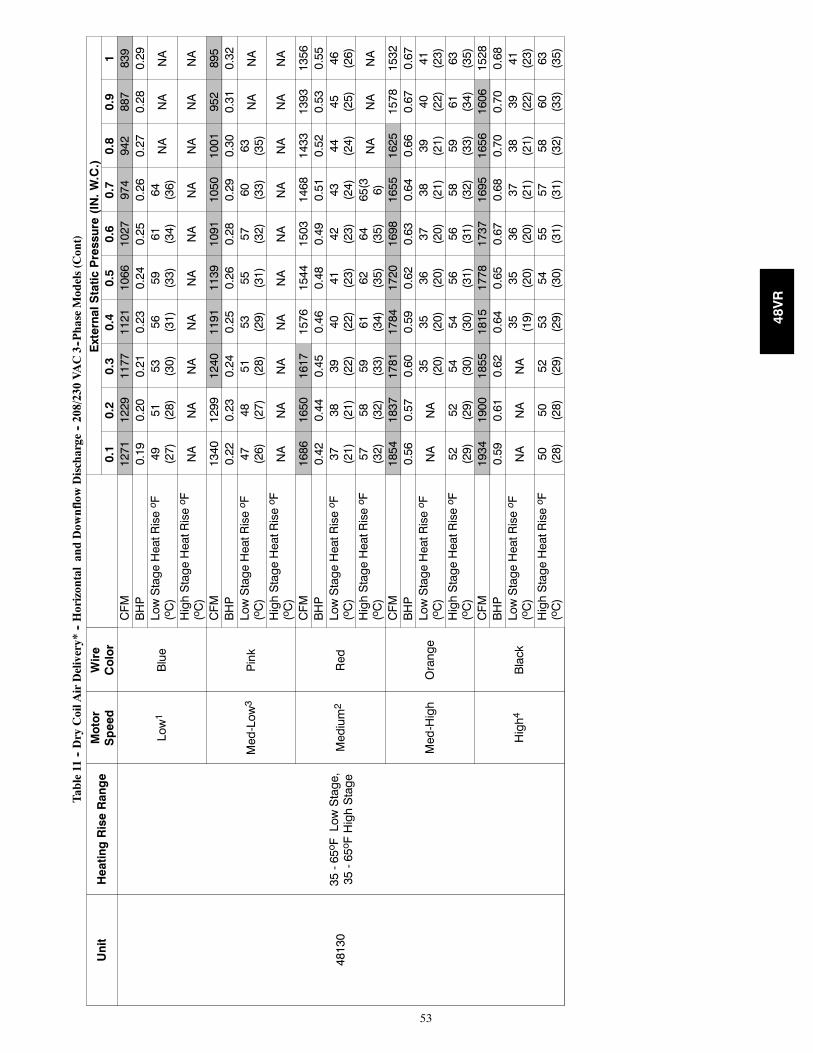
53
Table11
--DryCoilA
irDelivery*
--HorizontalandDow
nflowDischarge
--208/230VAC3--PhaseModels(Cont)
Unit
HeatingRiseRange
Motor
Speed
Wire
Color
ExternalStaticPressure(IN.W.C.)
0.1
0.2
0.3
0.4
0.5
0.6
0.7
0.8
0.9
1
48130
35-65oFLowStage,
35-65oFHighStage
Low1
Blue
CFM
1271
1229
1177
1121
1066
1027
974
942
887
839
BHP
0.19
0.20
0.21
0.23
0.24
0.25
0.26
0.27
0.28
0.29
LowStageHeatRiseo F
(oC)
49 (27)
51 (28)
53 (30)
56 (31)
59 (33)
61 (34)
64 (36)
NA
NA
NA
HighStageHeatRiseo F
(oC)
NA
NA
NA
NA
NA
NA
NA
NA
NA
NA
Med-Low3
Pink
CFM
1340
1299
1240
1191
1139
1091
1050
1001
952
895
BHP
0.22
0.23
0.24
0.25
0.26
0.28
0.29
0.30
0.31
0.32
LowStageHeatRiseo F
(oC)
47 (26)
48 (27)
51 (28)
53 (29)
55 (31)
57 (32)
60 (33)
63 (35)
NA
NA
HighStageHeatRiseo F
(oC)
NA
NA
NA
NA
NA
NA
NA
NA
NA
NA
Medium2
Red
CFM
1686
1650
1617
1576
1544
1503
1468
1433
1393
1356
BHP
0.42
0.44
0.45
0.46
0.48
0.49
0.51
0.52
0.53
0.55
LowStageHeatRiseo F
(oC)
37 (21)
38 (21)
39 (22)
40 (22)
41 (23)
42 (23)
43 (24)
44 (24)
45 (25)
46 (26)
HighStageHeatRiseo F
(oC)
57 (32)
58 (32)
59 (33)
61 (34)
62 (35)
64 (35)
65(3 6)
NA
NA
NA
Med-High
Orange
CFM
1854
1837
1781
1784
1720
1698
1655
1625
1578
1532
BHP
0.56
0.57
0.60
0.59
0.62
0.63
0.64
0.66
0.67
0.67
LowStageHeatRiseo F
(oC)
NA
NA
35 (20)
35 (20)
36 (20)
37 (20)
38 (21)
39 (21)
40 (22)
41 (23)
HighStageHeatRiseo F
(oC)
52 (29)
52 (29)
54 (30)
54 (30)
56 (31)
56 (31)
58 (32)
59 (33)
61 (34)
63 (35)
High4
Black
CFM
1934
1900
1855
1815
1778
1737
1695
1656
1606
1528
BHP
0.59
0.61
0.62
0.64
0.65
0.67
0.68
0.70
0.70
0.68
LowStageHeatRiseo F
(oC)
NA
NA
NA
35 (19)
35 (20)
36 (20)
37 (21)
38 (21)
39 (22)
41 (23)
HighStageHeatRiseo F
(oC)
50 (28)
50 (28)
52 (29)
53 (29)
54 (30)
55 (31)
57 (31)
58 (32)
60 (33)
63 (35)
48VR
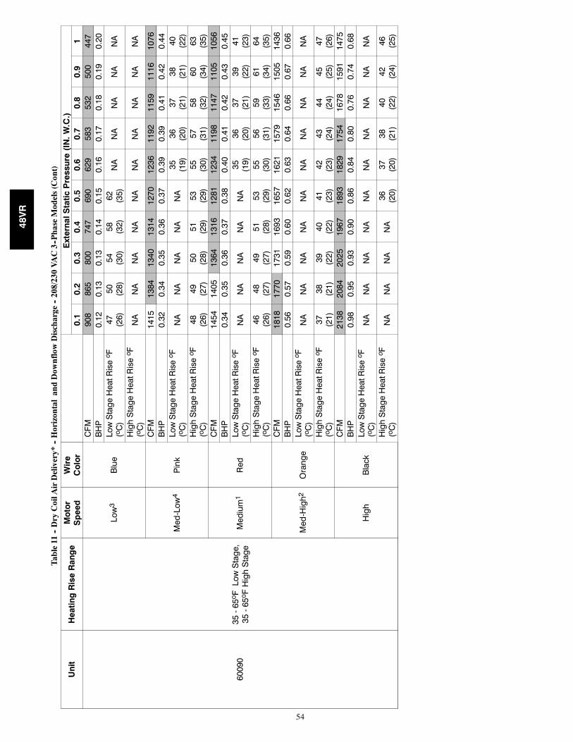
54
Table11
--DryCoilA
irDelivery*
--HorizontalandDow
nflowDischarge
--208/230VAC3--PhaseModels(Cont)
Unit
HeatingRiseRange
Motor
Speed
Wire
Color
ExternalStaticPressure(IN.W.C.)
0.1
0.2
0.3
0.4
0.5
0.6
0.7
0.8
0.9
1
60090
35-65oFLowStage,
35-65oFHighStage
Low3
Blue
CFM
908
865
800
747
690
629
583
532
500
447
BHP
0.12
0.13
0.13
0.14
0.15
0.16
0.17
0.18
0.19
0.20
LowStageHeatRiseo F
(oC)
47 (26)
50 (28)
54 (30)
58 (32)
62 (35)
NA
NA
NA
NA
NA
HighStageHeatRiseo F
(oC)
NA
NA
NA
NA
NA
NA
NA
NA
NA
NA
Med-Low4
Pink
CFM
1415
1384
1340
1314
1270
1236
1192
1159
1116
1076
BHP
0.32
0.34
0.35
0.36
0.37
0.39
0.39
0.41
0.42
0.44
LowStageHeatRiseo F
(oC)
NA
NA
NA
NA
NA
35 (19)
36 (20)
37 (21)
38 (21)
40 (22)
HighStageHeatRiseo F
(oC)
48 (26)
49 (27)
50 (28)
51 (29)
53 (29)
55 (30)
57 (31)
58 (32)
60 (34)
63 (35)
Medium1
Red
CFM
1454
1405
1364
1316
1281
1234
1198
1147
1105
1056
BHP
0.34
0.35
0.36
0.37
0.38
0.40
0.41
0.42
0.43
0.45
LowStageHeatRiseo F
(oC)
NA
NA
NA
NA
NA
35 (19)
36 (20)
37 (21)
39 (22)
41 (23)
HighStageHeatRiseo F
(oC)
46 (26)
48 (27)
49 (27)
51 (28)
53 (29)
55 (30)
56 (31)
59 (33)
61 (34)
64 (35)
Med-High2
Orange
CFM
1818
1770
1731
1693
1657
1621
1579
1546
1505
1436
BHP
0.56
0.57
0.59
0.60
0.62
0.63
0.64
0.66
0.67
0.66
LowStageHeatRiseo F
(oC)
NA
NA
NA
NA
NA
NA
NA
NA
NA
NA
HighStageHeatRiseo F
(oC)
37 (21)
38 (21)
39 (22)
40 (22)
41 (23)
42 (23)
43 (24)
44 (24)
45 (25)
47 (26)
High
Black
CFM
2138
2084
2025
1967
1893
1829
1754
1678
1591
1475
BHP
0.98
0.95
0.93
0.90
0.86
0.84
0.80
0.76
0.74
0.68
LowStageHeatRiseo F
(oC)
NA
NA
NA
NA
NA
NA
NA
NA
NA
NA
HighStageHeatRiseo F
(oC)
NA
NA
NA
NA
36 (20)
37 (20)
38 (21)
40 (22)
42 (24)
46 (25)
48VR
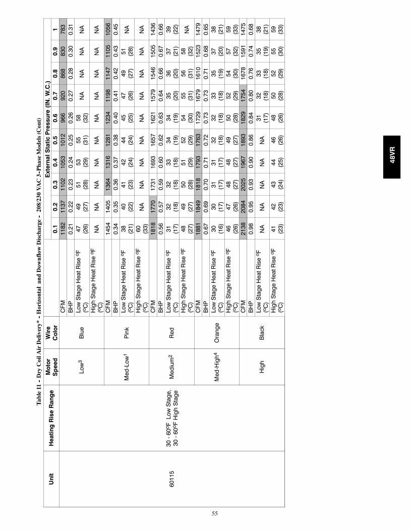
55
Table11
--DryCoilA
irDelivery*
--HorizontalandDow
nflowDischarge
--208/230VAC3--PhaseModels(Cont)
Unit
HeatingRiseRange
Motor
Speed
Wire
Color
ExternalStaticPressure(IN.W.C.)
0.1
0.2
0.3
0.4
0.5
0.6
0.7
0.8
0.9
1
60115
30-60oFLowStage,
30-60oFHighStage
Low3
Blue
CFM
1182
1137
1102
1053
1012
966
920
868
830
783
BHP
0.21
0.22
0.23
0.24
0.25
0.26
0.27
0.28
0.30
0.31
LowStageHeatRiseo F
(oC)
47 (26)
49 (27)
51 (28)
53 (29)
55 (31)
58 (32)
NA
NA
NA
NA
HighStageHeatRiseo F
(oC)
NA
NA
NA
NA
NA
NA
NA
NA
NA
NA
Med-Low1
Pink
CFM
1454
1405
1364
1316
1281
1234
1198
1147
1105
1056
BHP
0.34
0.35
0.36
0.37
0.38
0.40
0.41
0.42
0.43
0.45
LowStageHeatRiseo F
(oC)
38 (21)
40 (22)
41 (23)
42 (24)
44 (24)
45 (25)
47 (26)
49 (27)
51 (28)
NA
HighStageHeatRiseo F
(oC)
60 (33)
NA
NA
NA
NA
NA
NA
NA
NA
NA
Medium2
Red
CFM
1818
1770
1731
1693
1657
1621
1579
1546
1505
1436
BHP
0.56
0.57
0.59
0.60
0.62
0.63
0.64
0.66
0.67
0.66
LowStageHeatRiseo F
(oC)
31 (17)
32 (18)
32 (18)
33 (18)
34 (19)
34 (19)
35 (20)
36 (20)
37 (21)
39 (22)
HighStageHeatRiseo F
(oC)
48 (27)
49 (27)
50 (28)
51 (29)
52 (29)
54 (30)
55 (31)
56 (31)
58 (32)
NA
Med-High4
Orange
CFM
1881
1849
1818
1793
1763
1729
1679
1610
1523
1479
BHP
0.67
0.69
0.70
0.71
0.72
0.73
0.73
0.71
0.68
0.65
LowStageHeatRiseo F
(oC)
30 (16)
30 (17)
31 (17)
31 (17)
32 (18)
32 (18)
33 (18)
35 (19)
37 (20)
38 (21)
HighStageHeatRiseo F
(oC)
46 (26)
47 (26)
48 (27)
48 (27)
49 (27)
50 (28)
52 (29)
54 (30)
57 (32)
59 (33)
High
Black
CFM
2138
2084
2025
1967
1893
1829
1754
1678
1591
1475
BHP
0.98
0.95
0.93
0.90
0.86
0.84
0.80
0.76
0.74
0.68
LowStageHeatRiseo F
(oC)
NA
NA
NA
NA
NA
31 (17)
32 (18)
33 (18)
35 (19)
38 (21)
HighStageHeatRiseo F
(oC)
41 (23)
42 (23)
43 (24)
44 (25)
46 (26)
48 (26)
50 (28)
52 (29)
55 (30)
59 (33)
48VR
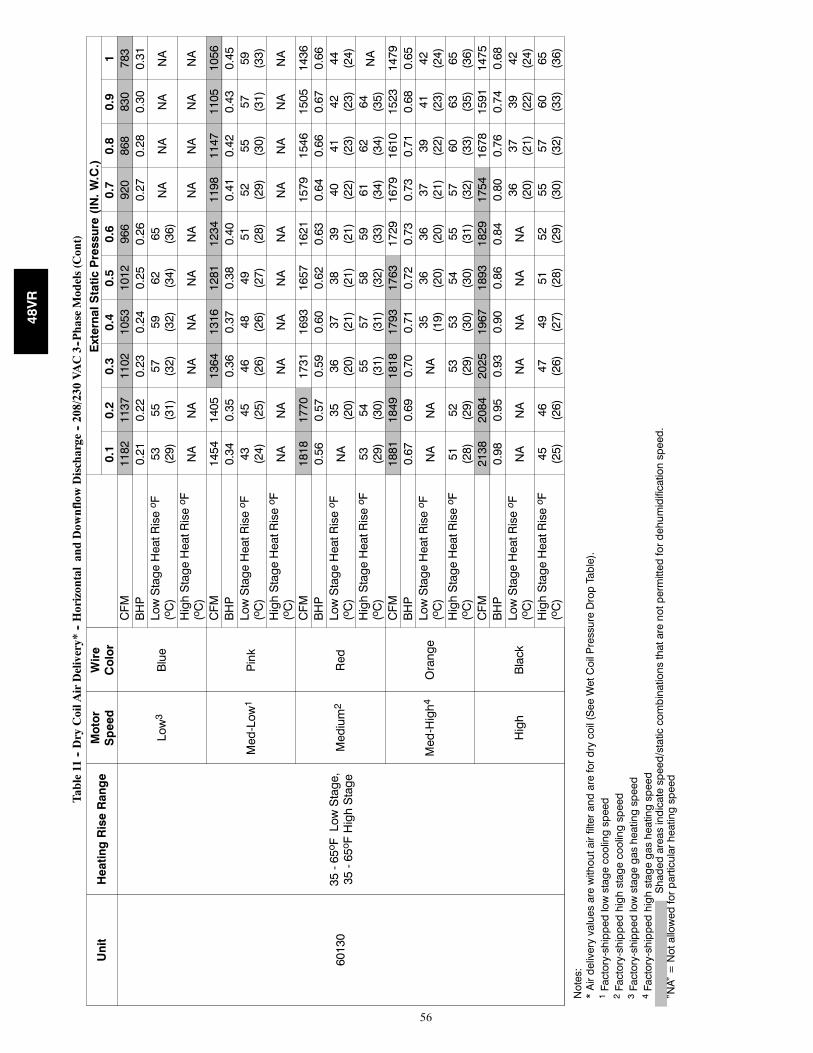
56
Table11
--DryCoilA
irDelivery*
--HorizontalandDow
nflowDischarge
--208/230VAC3--PhaseModels(Cont)
Unit
HeatingRiseRange
Motor
Speed
Wire
Color
ExternalStaticPressure(IN.W.C.)
0.1
0.2
0.3
0.4
0.5
0.6
0.7
0.8
0.9
1
60130
35-65oFLowStage,
35-65oFHighStage
Low3
Blue
CFM
1182
1137
1102
1053
1012
966
920
868
830
783
BHP
0.21
0.22
0.23
0.24
0.25
0.26
0.27
0.28
0.30
0.31
LowStageHeatRiseo F
(oC)
53 (29)
55 (31)
57 (32)
59 (32)
62 (34)
65 (36)
NA
NA
NA
NA
HighStageHeatRiseo F
(oC)
NA
NA
NA
NA
NA
NA
NA
NA
NA
NA
Med-Low1
Pink
CFM
1454
1405
1364
1316
1281
1234
1198
1147
1105
1056
BHP
0.34
0.35
0.36
0.37
0.38
0.40
0.41
0.42
0.43
0.45
LowStageHeatRiseo F
(oC)
43 (24)
45 (25)
46 (26)
48 (26)
49 (27)
51 (28)
52 (29)
55 (30)
57 (31)
59 (33)
HighStageHeatRiseo F
(oC)
NA
NA
NA
NA
NA
NA
NA
NA
NA
NA
Medium2
Red
CFM
1818
1770
1731
1693
1657
1621
1579
1546
1505
1436
BHP
0.56
0.57
0.59
0.60
0.62
0.63
0.64
0.66
0.67
0.66
LowStageHeatRiseo F
(oC)
NA
35 (20)
36 (20)
37 (21)
38 (21)
39 (21)
40 (22)
41 (23)
42 (23)
44 (24)
HighStageHeatRiseo F
(oC)
53 (29)
54 (30)
55 (31)
57 (31)
58 (32)
59 (33)
61 (34)
62 (34)
64 (35)
NA
Med-High4
Orange
CFM
1881
1849
1818
1793
1763
1729
1679
1610
1523
1479
BHP
0.67
0.69
0.70
0.71
0.72
0.73
0.73
0.71
0.68
0.65
LowStageHeatRiseo F
(oC)
NA
NA
NA
35 (19)
36 (20)
36 (20)
37 (21)
39 (22)
41 (23)
42 (24)
HighStageHeatRiseo F
(oC)
51 (28)
52 (29)
53 (29)
53 (30)
54 (30)
55 (31)
57 (32)
60 (33)
63 (35)
65 (36)
High
Black
CFM
2138
2084
2025
1967
1893
1829
1754
1678
1591
1475
BHP
0.98
0.95
0.93
0.90
0.86
0.84
0.80
0.76
0.74
0.68
LowStageHeatRiseo F
(oC)
NA
NA
NA
NA
NA
NA
36 (20)
37 (21)
39 (22)
42 (24)
HighStageHeatRiseo F
(oC)
45 (25)
46 (26)
47 (26)
49 (27)
51 (28)
52 (29)
55 (30)
57 (32)
60 (33)
65 (36)
Notes:
*Airdeliveryvaluesarewithoutairfilterandarefordrycoil(SeeWetCoilPressureDropTable).
1Factory-shippedlowstagecoolingspeed
2Factory-shippedhighstagecoolingspeed
3Factory-shippedlowstagegasheatingspeed
4Factory-shippedhighstagegasheatingspeed
Shadedareasindicatespeed/staticcombinationsthatarenotpermittedfordehumidificationspeed.
”NA”=Notallowedforparticularheatingspeed
48VR
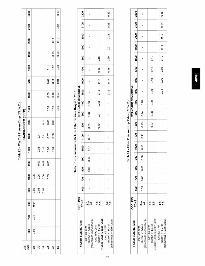
57
Table12
–WetCoilPressureDrop(IN.W
.C.)
UNIT
SIZE
STA
NDARDCFM(SCFM)
600
700
800
900
1000
1100
1200
1300
1400
1500
1600
1700
1800
1900
2000
2100
2200
240.
030.
040.
040.
050.
06
300.
050.
060.
070.
080.
11
360.
060.
060.
090.
100.
110.
14
420.
050.
050.
060.
070.
080.
080.
090.
090.
11
480.
040.
060.
090.
100.
100.
110.
120.
130.
14
600.
060.
070.
010.
080.
090.
100.
120.
13
Table13
–Economizerwith1--in.FilterPressureDrop(IN.W
.C.)
FILTERSIZEIN.(MM)
COOLING
TONS
STA
NDARDCFM(SCFM)
600
700
800
900
1000
1100
1200
1300
1400
1500
1600
1700
1800
1900
2000
2100
2200
600-1400CFM
12x20x1+12x20x1
(305x508x25+305x508x25)
2.0,
2.5
----
0.09
0.14
0.16
0.18
0.25
0.28
0.30
----
----
----
----
1200-1800CFM
16x24x1+14x24x1
(406
x610
x25+
356x
610x
25)
3.0
3.5
----
----
----
0.10
0.11
0.12
0.13
0.14
0.16
0.16
----
----
1500-2200CFM
16x24x1+18x24x1
(406x610x25+457x610x25)
4.0
5.0
----
----
----
----
--0.
150.
170.
180.
200.
210.
220.
230.
23
Table14
–FilterPressureDropTable(IN.W
.C.)
FILTERSIZEIN.(MM)
COOLING
TONS
STA
NDARDCFM(SCFM)
600
700
800
900
1000
1100
1200
1300
1400
1500
1600
1700
1800
1900
2000
2100
2200
600-1400CFM
12x20x1+12x20x1
(305x508x25+305x508x25)
2.0,
2.5
0.03
0.05
0.06
0.08
0.10
0.11
0.13
0.14
0.16
----
----
----
----
1200-1800CFM
16x24x1+14x24x1
(406
x610
x25+
356x
610x
25)
3.0
3.5
----
----
----
0.07
0.08
0.09
0.09
0.10
0.11
0.12
----
----
1500-2200CFM
16x24x1+18x24x1
(406x610x25+457x610x25)
4.0
5.0
----
----
----
----
--0.
040.
060.
080.
100.
110.
130.
140.
15
48VR
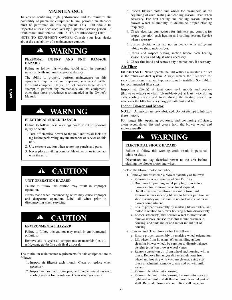
58
MAINTENANCETo ensure continuing high performance and to minimize thepossibility of premature equipment failure, periodic maintenancemust be performed on this equipment. This unit should beinspected at least once each year by a qualified service person. Totroubleshoot unit, refer to Table 15--17, Troubleshooting Chart.
NOTE TO EQUIPMENT OWNER: Consult your local dealerabout the availability of a maintenance contract.
PERSONAL INJURY AND UNIT DAMAGEHAZARD
Failure to follow this warning could result in personalinjury or death and unit component damage.
The ability to properly perform maintenance on thisequipment requires certain expertise, mechanical skills,tools and equipment. If you do not possess these, do notattempt to perform any maintenance on this equipment,other than those procedures recommended in the Owner’sManual.
! WARNING
ELECTRICAL SHOCK HAZARD
Failure to follow these warnings could result in personalinjury or death:
1. Turn off electrical power to the unit and install lock outtag before performing any maintenance or service on thisunit.
2. Use extreme caution when removing panels and parts.
3. Never place anything combustible either on or in contactwith the unit.
! WARNING
UNIT OPERATION HAZARD
Failure to follow this caution may result in improperoperation.
Errors made when reconnecting wires may cause improperand dangerous operation. Label all wires prior todisconnecting when servicing.
CAUTION!
ENVIRONMENTAL HAZARD
Failure to follow this caution may result in environmentalpollution.
Remove and re--cycle all components or materials (i.e. oil,refrigerant, etc) before unit final disposal.
! CAUTION
The minimum maintenance requirements for this equipment are asfollows:
1. Inspect air filter(s) each month. Clean or replace whennecessary.
2. Inspect indoor coil, drain pan, and condensate drain eachcooling season for cleanliness. Clean when necessary.
3. Inspect blower motor and wheel for cleanliness at thebeginning of each heating and cooling season. Clean whennecessary. For first heating and cooling season, inspectblower wheel bi--monthly to determine proper cleaningfrequency.
4. Check electrical connections for tightness and controls forproper operation each heating and cooling season. Servicewhen necessary.
5. Ensure electric wires are not in contact with refrigeranttubing or sharp metal edges.
6. Check and inspect heating section before each heatingseason. Clean and adjust when necessary.
7. Check flue hood and remove any obstructions, if necessary.
Air FilterIMPORTANT: Never operate the unit without a suitable air filterin the return--air duct system. Always replace the filter with thesame dimensional size and type as originally installed. See Table 1for recommended filter sizes.
Inspect air filter(s) at least once each month and replace(throwaway--type) or clean (cleanable--type) at least twice duringeach cooling season and twice during the heating season, orwhenever the filter becomes clogged with dust and lint.
Indoor Blower and MotorNOTE: All motors are pre--lubricated. Do not attempt to lubricatethese motors.
For longer life, operating economy, and continuing efficiency,clean accumulated dirt and grease from the blower wheel andmotor annually.
ELECTRICAL SHOCK HAZARD
Failure to follow this warning could result in personalinjury or death.
Disconnect and tag electrical power to the unit beforecleaning the blower motor and wheel.
! WARNING
To clean the blower motor and wheel:
1. Remove and disassemble blower assembly as follows:a. Remove blower access panel (see Fig. 19).b. Disconnect 5 pin plug and 4 pin plug from indoorblower motor. Remove capacitor if required.
c. On all units remove blower assembly from unit.Remove screws securing blower to blower partition andslide assembly out. Be careful not to tear insulation inblower compartment.
d. Ensure proper reassembly by marking blower wheel andmotor in relation to blower housing before disassembly.
e. Loosen setscrew(s) that secures wheel to motor shaft,remove screws that secure motor mount brackets tohousing, and slide motor and motor mount out ofhousing.
2. Remove and clean blower wheel as follows:a. Ensure proper reassembly by marking wheel orientation.b. Lift wheel from housing. When handling and/orcleaning blower wheel, be sure not to disturb balanceweights (clips) on blower wheel vanes.
c. Remove caked--on dirt from wheel and housing with abrush. Remove lint and/or dirt accumulations fromwheel and housing with vacuum cleaner, using softbrush attachment. Remove grease and oil with mildsolvent.
d. Reassemble wheel into housing.e. Reassemble motor into housing. Be sure setscrews aretightened on motor shaft flats and not on round part ofshaft. Reinstall blower into unit. Reinstall capacitor.
48VR
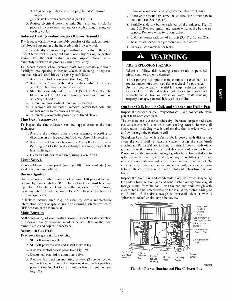
59
f. Connect 5 pin plug and 4 pin plug to indoor blowermotor.
g. Reinstall blower access panel (see Fig. 19).3. Restore electrical power to unit. Start unit and check forproper blower rotation and motor speeds during heating andcooling cycles.
Induced Draft (combustion air) Blower AssemblyThe induced--draft blower assembly consists of the inducer motor,the blower housing, and the induced--draft blower wheel.
Clean periodically to assure proper airflow and heating efficiency.Inspect blower wheel every fall and periodically during the heatingseason. For the first heating season, inspect blower wheelbimonthly to determine proper cleaning frequency.
To inspect blower wheel, remove draft hood assembly. Shine aflashlight into opening to inspect wheel. If cleaning is required,remove induced--draft blower assembly as follows:
1. Remove control access panel (See Fig. 19).2. Remove the 5 screws that attach induced--draft blower as-sembly to the flue collector box cover.
3. Slide the assembly out of the unit. (See Fig. 21). Clean theblower wheel. If additional cleaning is required, continuewith Steps 4 and 5.
4. To remove blower wheel, remove 2 setscrews.5. To remove inducer motor, remove screws that hold theinducer motor to the blower housing.
6. To reinstall, reverse the procedure outlined above.Flue Gas PassagewaysTo inspect the flue collector box and upper areas of the heatexchanger:
1. Remove the induced draft blower assembly according todirections in the Induced Draft Blower Assembly section.
2. Remove the 11 screws holding the flue collector box cover(See Fig. 18) to the heat exchanger assembly. Inspect theheat exchangers.
3. Clean all surfaces, as required, using a wire brush.
Limit SwitchRemove blower access panel (see Fig. 19). Limit switch(es) arelocated on the fan partition.
Burner IgnitionUnit is equipped with a direct spark ignition 100 percent lockoutsystem. Ignition module (IGC) is located in the control box (SeeFig. 18). Module contains a self--diagnostic LED. Duringservicing, refer to label diagram or Table 6 in these instructions forLED interpretation.
If lockout occurs, unit may be reset by either momentarilyinterrupting power supply to unit or by turning selector switch toOFF position at the thermostat.
Main BurnersAt the beginning of each heating season, inspect for deteriorationor blockage due to corrosion or other causes. Observe the mainburner flames and adjust, if necessary.
Removal of Gas TrainTo remove the gas train for servicing:
1. Shut off main gas valve.
2. Shut off power to unit and install lockout tag.
3. Remove control access panel (See Fig. 19).
4. Disconnect gas piping at unit gas valve.
5. Remove fan partition mounting bracket (2 screws locatedon the left side of control compartment on the fan partitionpanel). Slide bracket forward, bottom first, to remove. (SeeFig. 18.)
6. Remove wires connected to gas valve. Mark each wire.
7. Remove the mounting screw that attaches the burner rack tothe unit base (See Fig. 18).
8. Partially slide the burner rack out of the unit (see Fig. 18and 21). Remove ignitor and sensor wires at the burner as-sembly. Remove wires to rollout switch.
9. Slide the burner rack out of the unit (See Fig. 18 and 21).
10. To reinstall, reverse the procedure outlined above.
11. Check all connections for leaks.
FIRE, EXPLOSION HAZARD
Failure to follow this warning could result in personalinjury, death or property damage.
Do not purge gas supply into the combustion chamber. Donot use a match or other open flame to check for gas leaks.Use a commercially available soap solution madespecifically for the detection of leaks to check allconnections. A fire or explosion may result causingproperty damage, personal injury or loss of life.
! WARNING
Outdoor Coil, Indoor Coil, and Condensate Drain PanInspect the condenser coil, evaporator coil, and condensate drainpan at least once each year.
The coils are easily cleaned when dry; therefore, inspect and cleanthe coils either before or after each cooling season. Remove allobstructions, including weeds and shrubs, that interfere with theairflow through the condenser coil.
Straighten bent fins with a fin comb. If coated with dirt or lint,clean the coils with a vacuum cleaner, using the soft brushattachment. Be careful not to bend the fins. If coated with oil orgrease, clean the coils with a mild detergent and water solution.Rinse coils with clear water, using a garden hose. Be careful not tosplash water on motors, insulation, wiring, or air filter(s). For bestresults, spray condenser coil fins from inside to outside the unit. Onunits with an outer and inner condenser coil, be sure to cleanbetween the coils. Be sure to flush all dirt and debris from the unitbase.
Inspect the drain pan and condensate drain line when inspectingthe coils. Clean the drain pan and condensate drain by removing allforeign matter from the pan. Flush the pan and drain trough withclear water. Do not splash water on the insulation, motor, wiring, orair filter(s). If the drain trough is restricted, clear it with a“plumbers snake” or similar probe device.
Integrated Gas UnitController(IGC)
Induced DraftMotor
RolloutSwitchMounting
ScrewBurnerRack
InducerBlowerHousing
FlueCollector Box
Interface FanBoard (IFB)
Auto Transformerfuses used on 460volt units only.(Hidden)
Fan PartitionMountingBracket
A09193
Fig. 18 -- Blower Housing and Flue Collector Box
48VR
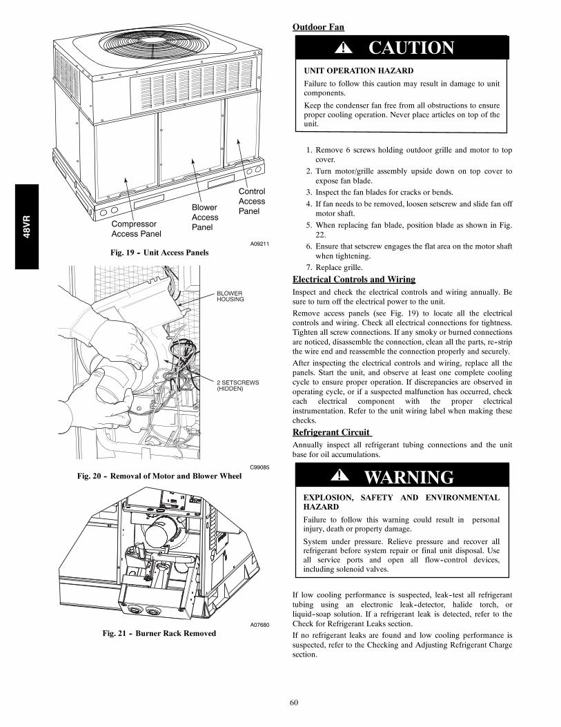
60
CompressorAccess Panel
ControlAccessPanelBlower
AccessPanel
A09211
Fig. 19 -- Unit Access Panels
BLOWERHOUSING
2 SETSCREWS(HIDDEN)
C99085
Fig. 20 -- Removal of Motor and Blower Wheel
A07680
Fig. 21 -- Burner Rack Removed
Outdoor Fan
UNIT OPERATION HAZARD
Failure to follow this caution may result in damage to unitcomponents.
Keep the condenser fan free from all obstructions to ensureproper cooling operation. Never place articles on top of theunit.
CAUTION!
1. Remove 6 screws holding outdoor grille and motor to topcover.
2. Turn motor/grille assembly upside down on top cover toexpose fan blade.
3. Inspect the fan blades for cracks or bends.
4. If fan needs to be removed, loosen setscrew and slide fan offmotor shaft.
5. When replacing fan blade, position blade as shown in Fig.22.
6. Ensure that setscrew engages the flat area on the motor shaftwhen tightening.
7. Replace grille.
Electrical Controls and WiringInspect and check the electrical controls and wiring annually. Besure to turn off the electrical power to the unit.
Remove access panels (see Fig. 19) to locate all the electricalcontrols and wiring. Check all electrical connections for tightness.Tighten all screw connections. If any smoky or burned connectionsare noticed, disassemble the connection, clean all the parts, re--stripthe wire end and reassemble the connection properly and securely.
After inspecting the electrical controls and wiring, replace all thepanels. Start the unit, and observe at least one complete coolingcycle to ensure proper operation. If discrepancies are observed inoperating cycle, or if a suspected malfunction has occurred, checkeach electrical component with the proper electricalinstrumentation. Refer to the unit wiring label when making thesechecks.
Refrigerant CircuitAnnually inspect all refrigerant tubing connections and the unitbase for oil accumulations.
EXPLOSION, SAFETY AND ENVIRONMENTALHAZARD
Failure to follow this warning could result in personalinjury, death or property damage.
System under pressure. Relieve pressure and recover allrefrigerant before system repair or final unit disposal. Useall service ports and open all flow--control devices,including solenoid valves.
! WARNING
If low cooling performance is suspected, leak--test all refrigeranttubing using an electronic leak--detector, halide torch, orliquid--soap solution. If a refrigerant leak is detected, refer to theCheck for Refrigerant Leaks section.
If no refrigerant leaks are found and low cooling performance issuspected, refer to the Checking and Adjusting Refrigerant Chargesection.
48VR
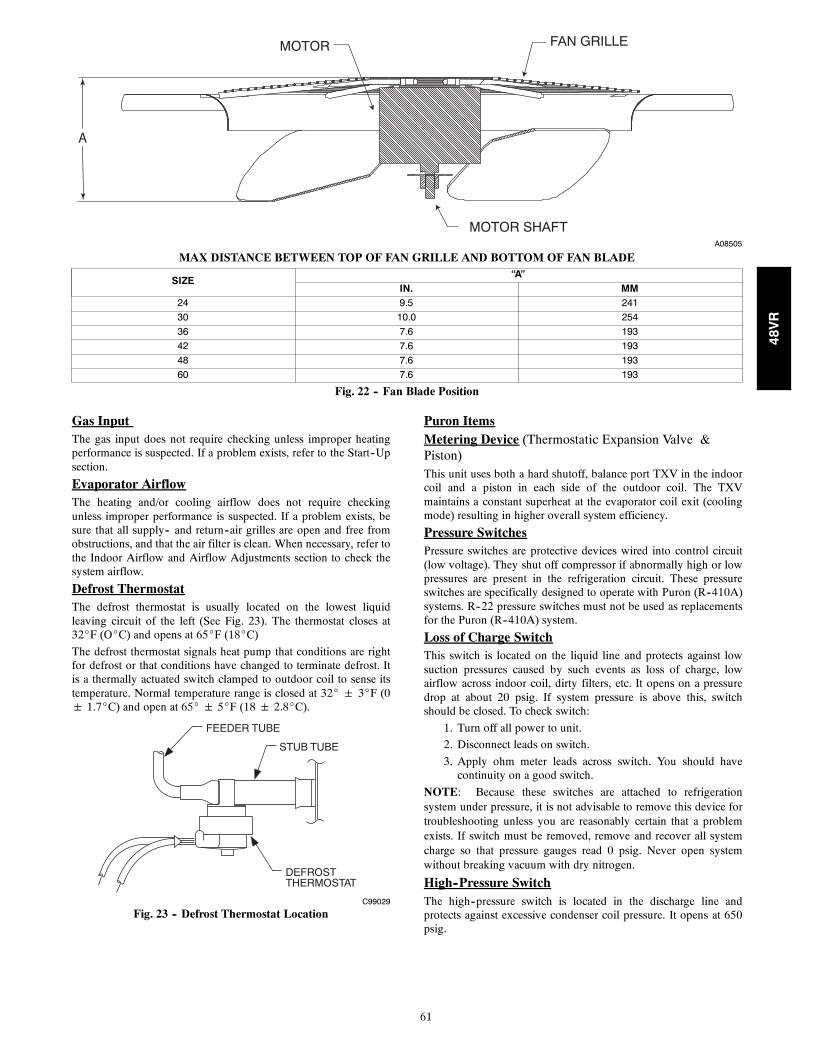
61
MOTOR FAN GRILLE
MOTOR SHAFT
A
A08505
MAX DISTANCE BETWEEN TOP OF FAN GRILLE AND BOTTOM OF FAN BLADE
SIZE“A”
IN. MM24 9.5 24130 10.0 25436 7.6 19342 7.6 19348 7.6 19360 7.6 193
Fig. 22 -- Fan Blade Position
Gas InputThe gas input does not require checking unless improper heatingperformance is suspected. If a problem exists, refer to the Start--Upsection.
Evaporator AirflowThe heating and/or cooling airflow does not require checkingunless improper performance is suspected. If a problem exists, besure that all supply-- and return--air grilles are open and free fromobstructions, and that the air filter is clean. When necessary, refer tothe Indoor Airflow and Airflow Adjustments section to check thesystem airflow.
Defrost ThermostatThe defrost thermostat is usually located on the lowest liquidleaving circuit of the left (See Fig. 23). The thermostat closes at32_F (O_C) and opens at 65_F (18_C)
The defrost thermostat signals heat pump that conditions are rightfor defrost or that conditions have changed to terminate defrost. Itis a thermally actuated switch clamped to outdoor coil to sense itstemperature. Normal temperature range is closed at 32_ 3_F (0 1.7_C) and open at 65_ 5_F (18 2.8_C).
FEEDER TUBE
STUB TUBE
DEFROSTTHERMOSTAT
C99029
Fig. 23 -- Defrost Thermostat Location
Puron ItemsMetering Device (Thermostatic Expansion Valve &Piston)This unit uses both a hard shutoff, balance port TXV in the indoorcoil and a piston in each side of the outdoor coil. The TXVmaintains a constant superheat at the evaporator coil exit (coolingmode) resulting in higher overall system efficiency.
Pressure SwitchesPressure switches are protective devices wired into control circuit(low voltage). They shut off compressor if abnormally high or lowpressures are present in the refrigeration circuit. These pressureswitches are specifically designed to operate with Puron (R--410A)systems. R--22 pressure switches must not be used as replacementsfor the Puron (R--410A) system.
Loss of Charge SwitchThis switch is located on the liquid line and protects against lowsuction pressures caused by such events as loss of charge, lowairflow across indoor coil, dirty filters, etc. It opens on a pressuredrop at about 20 psig. If system pressure is above this, switchshould be closed. To check switch:
1. Turn off all power to unit.
2. Disconnect leads on switch.
3. Apply ohm meter leads across switch. You should havecontinuity on a good switch.
NOTE: Because these switches are attached to refrigerationsystem under pressure, it is not advisable to remove this device fortroubleshooting unless you are reasonably certain that a problemexists. If switch must be removed, remove and recover all systemcharge so that pressure gauges read 0 psig. Never open systemwithout breaking vacuum with dry nitrogen.
High--Pressure SwitchThe high--pressure switch is located in the discharge line andprotects against excessive condenser coil pressure. It opens at 650psig.
48VR
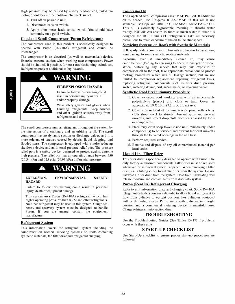
62
High pressure may be caused by a dirty outdoor coil, failed fanmotor, or outdoor air recirculation. To check switch:
1. Turn off all power to unit.
2. Disconnect leads on switch.
3. Apply ohm meter leads across switch. You should havecontinuity on a good switch.
Copeland Scroll Compressor (Puron Refrigerant)The compressor used in this product is specifically designed tooperate with Puron (R--410A) refrigerant and cannot beinterchanged.
The compressor is an electrical (as well as mechanical) device.Exercise extreme caution when working near compressors. Powershould be shut off, if possible, for most troubleshooting techniques.Refrigerants present additional safety hazards.
FIRE/EXPLOSION HAZARD
Failure to follow this warning couldresult in personal injury or deathand/or property damage.
Wear safety glasses and gloves whenhandling refrigerants. Keep torchesand other ignition sources away fromrefrigerants and oils..
! WARNING
The scroll compressor pumps refrigerant throughout the system bythe interaction of a stationary and an orbiting scroll. The scrollcompressor has no dynamic suction or discharge valves, and it ismore tolerant of stresses caused by debris, liquid slugging, andflooded starts. The compressor is equipped with a noise reducingshutdown device and an internal pressure relief port. The pressurerelief port is a safety device, designed to protect against extremehigh pressure. The relief port has an operating range between 550(26.34 kPa) and 625 psig (29.93 kPa) differential pressure.
EXPLOSION, ENVIRONMENTAL SAFETYHAZARD
Failure to follow this warning could result in personalinjury, death or equipment damage.
This system uses Puron (R--410A) refrigerant which hashigher operating pressures than R--22 and other refrigerants.No other refrigerant may be used in this system. Gauge set,hoses, and recovery system must be designed to handlePuron. If you are unsure, consult the equipmentmanufacturer.
WARNING!
Refrigerant SystemThis information covers the refrigerant system including thecompressor oil needed, servicing systems on roofs containingsynthetic materials, the filter drier and refrigerant charging.
Compressor OilThe Copeland scroll compressor uses 3MAF POE oil. If additionaloil is needed, use Uniqema RL32--3MAF. If this oil is notavailable, use Copeland Ultra 32 CC or Mobil Arctic EAL22 CC.This oil is extremely hygroscopic, meaning it absorbs waterreadily. POE oils can absorb 15 times as much water as other oilsdesigned for HCFC and CFC refrigerants. Take all necessaryprecautions to avoid exposure of the oil to the atmosphere.
Servicing Systems on Roofs with Synthetic MaterialsPOE (polyolester) compressor lubricants are known to cause longterm damage to some synthetic roofing materials.
Exposure, even if immediately cleaned up, may causeembrittlement (leading to cracking) to occur in one year or more.When performing any service that may risk exposure ofcompressor oil to the roof, take appropriate precautions to protectroofing. Procedures which risk oil leakage include, but are notlimited to, compressor replacement, repairing refrigerant leaks,replacing refrigerant components such as filter drier, pressureswitch, metering device, coil, accumulator, or reversing valve.
Synthetic Roof Precautionary Procedure1. Cover extended roof working area with an impermeablepolyethylene (plastic) drip cloth or tarp. Cover anapproximate 10 X 10 ft. (3.1 m X 3.1 m) area.
2. Cover area in front of the unit service panel with a terrycloth shop towel to absorb lubricant spills and preventrun--offs, and protect drop cloth from tears caused by toolsor components.
3. Place terry cloth shop towel inside unit immediately undercomponent(s) to be serviced and prevent lubricant run--offsthrough the louvered openings in the unit base.
4. Perform required service.
5. Remove and dispose of any oil contaminated material perlocal codes.
Liquid Line Filter DrierThis filter drier is specifically designed to operate with Puron. Useonly factory--authorized components. Filter drier must be replacedwhenever the refrigerant system is opened. When removing a filterdrier, use a tubing cutter to cut the drier from the system. Do notunsweat a filter drier from the system. Heat from unsweating willrelease moisture and contaminants from drier into system.
Puron (R--410A) Refrigerant ChargingRefer to unit information plate and charging chart. Some R--410Arefrigerant cylinders contain a dip tube to allow liquid refrigerant toflow from cylinder in upright position. For cylinders equippedwith a dip tube, charge Puron units with cylinder in uprightposition and a commercial metering device in manifold hose.Charge refrigerant into suction--line.
TROUBLESHOOTINGUse the Troubleshooting Guides (See Tables 15--17) if problemsoccur with these units.
START--UP CHECKLISTUse Start--Up checklist to ensure proper start--up procedures arefollowed.
48VR
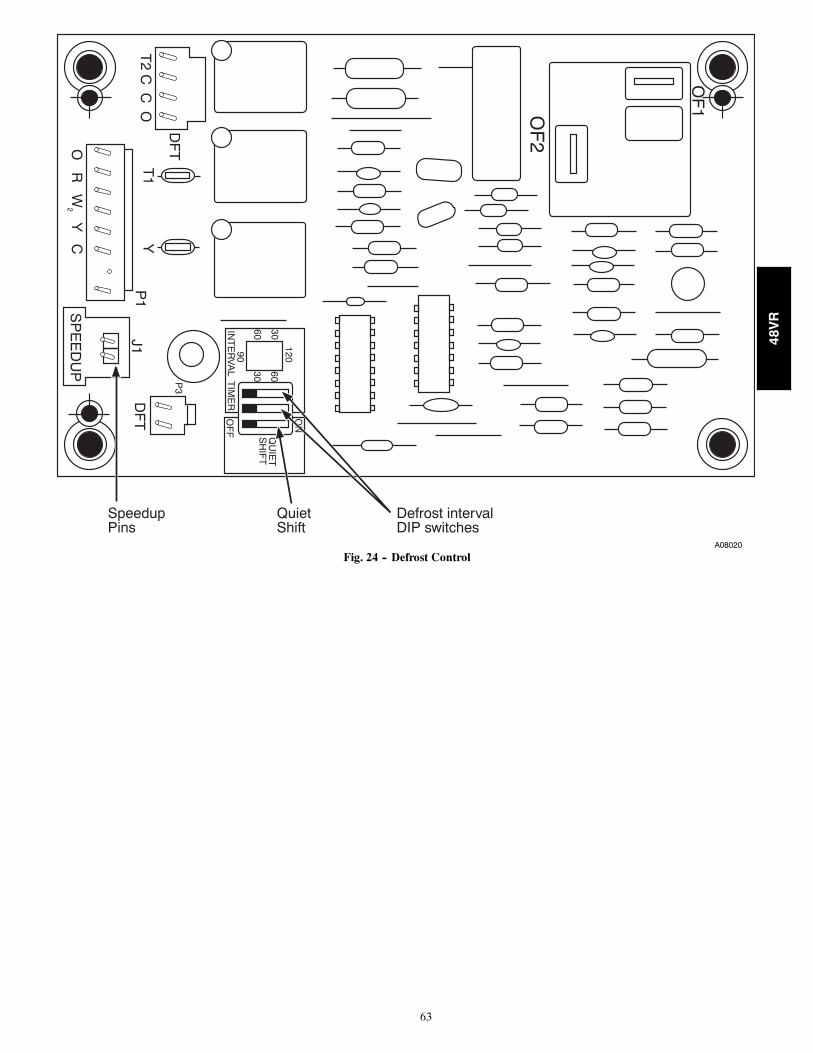
63
OF
2
OF
1
ON
QU
IET
SH
IFT
120
3060
6030
90IN
TE
RV
AL T
IME
RO
FF
P3
DF
T
O R
W2 Y
C
T2 C
C O
DF
T
T1
YP
1J1
SP
EE
DU
P
SpeedupPins
Defrost intervalDIP switches
QuietShift
A08020
Fig. 24 -- Defrost Control
48VR
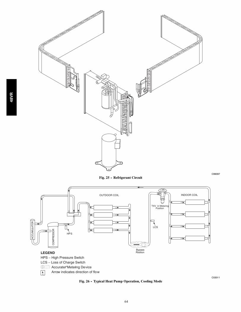
64
C99097
Fig. 25 -- Refrigerant Circuit
CO
MP
RE
SS
OR
AC
CU
MU
LATO
R
OUTDOOR COIL INDOOR COIL
LCS
LEGENDHPS – High Pressure SwitchLCS – Loss of Charge Switch
Accurater ® Metering De viceArrow indicates direction of flo w
TXV in Metering Position
BypassPosition
HP S
C03011
Fig. 26 -- Typical Heat Pump Operation, Cooling Mode
48VR
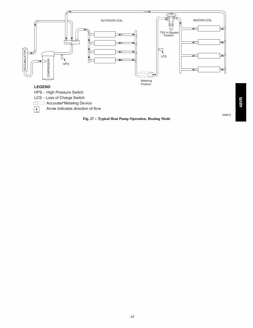
65
CO
MP
RE
SS
OR
AC
CU
MU
LATO
R
OUTDOOR COIL INDOOR COIL
LCS
LEGENDHPS – High Pressure SwitchLCS – Loss of Charge Switch
Accurater ® Metering De viceArrow indicates direction of flo w
Position
HP S
TXV in Bypass
MeteringPosition
C03012
Fig. 27 -- Typical Heat Pump Operation, Heating Mode
48VR
66
PURONR (R--410A) QUICK REFERENCE GUIDE
S Puron refrigerant operates at 50--70 percent higher pressures than R--22. Be sure that servicing equipment and replacement
components are designed to operate with Puron
S Puron refrigerant cylinders are rose colored.
S Recovery cylinder service pressure rating must be 400 psig, DOT 4BA400 or DOT BW400.
S Puron systems should be charged with liquid refrigerant. Use a commercial type metering device in the manifold hose when
charging into suction line with compressor operating
S Manifold sets should be minimum 700 psig high side and 180 psig low side with 550 psig low--side retard.
S Use hoses with minimum 700 psig service pressure rating.
S Leak detectors should be designed to detect HFC refrigerant.
S Puron, as with other HFCs, is only compatible with POE oils.
S Vacuum pumps will not remove moisture from oil.
S Do not use liquid--line filter driers with rated working pressures less than 600 psig.
S Do not leave Puron suction line filter driers in line longer than 72 hrs.
S Do not install a suction--line filter drier in liquid line.
S POE oils absorb moisture rapidly. Do not expose oil to atmosphere.
S POE oils may cause damage to certain plastics and roofing materials.
S Wrap all filter driers and service valves with wet cloth when brazing.
S A factory approved liquid--line filter drier is required on every unit.
S Do NOT use an R--22 TXV.
S Never open system to atmosphere while it is under a vacuum.
S When system must be opened for service, recover refrigerant, evacuate then break vacuum with dry nitrogen and replace filter
driers. Evacuate to 500 microns prior to recharging.
S Do not vent Puron into the atmosphere.
S Observe all warnings, cautions, and bold text.
S All indoor coils must be installed with a hard shutoff Puron TXV metering device.
48VR
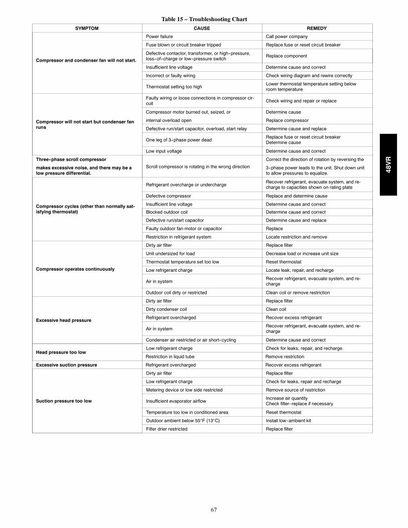
67
Table 15 – Troubleshooting Chart
SYMPTOM CAUSE REMEDY
Compressor and condenser fan will not start.
Power failure Call power company
Fuse blown or circuit breaker tripped Replace fuse or reset circuit breaker
Defective contactor, transformer, or high--pressure,loss--of--charge or low--pressure switch
Replace component
Insufficient line voltage Determine cause and correct
Incorrect or faulty wiring Check wiring diagram and rewire correctly
Thermostat setting too highLower thermostat temperature setting belowroom temperature
Compressor will not start but condenser fanruns
Faulty wiring or loose connections in compressor cir-cuit Check wiring and repair or replace
Compressor motor burned out, seized, or Determine cause
internal overload open Replace compressor
Defective run/start capacitor, overload, start relay Determine cause and replace
One leg of 3--phase power deadReplace fuse or reset circuit breakerDetermine cause
Low input voltage Determine cause and correct
Three--phase scroll compressor
Scroll compressor is rotating in the wrong direction
Correct the direction of rotation by reversing the
makes excessive noise, and there may be alow pressure differential.
3--phase power leads to the unit. Shut down unitto allow pressures to equalize.
Compressor cycles (other than normally sat-isfying thermostat)
Refrigerant overcharge or underchargeRecover refrigerant, evacuate system, and re-charge to capacities shown on rating plate
Defective compressor Replace and determine cause
Insufficient line voltage Determine cause and correct
Blocked outdoor coil Determine cause and correct
Defective run/start capacitor Determine cause and replace
Faulty outdoor fan motor or capacitor Replace
Restriction in refrigerant system Locate restriction and remove
Compressor operates continuously
Dirty air filter Replace filter
Unit undersized for load Decrease load or increase unit size
Thermostat temperature set too low Reset thermostat
Low refrigerant charge Locate leak, repair, and recharge
Air in systemRecover refrigerant, evacuate system, and re-charge
Outdoor coil dirty or restricted Clean coil or remove restriction
Excessive head pressure
Dirty air filter Replace filter
Dirty condenser coil Clean coil
Refrigerant overcharged Recover excess refrigerant
Air in systemRecover refrigerant, evacuate system, and re-charge
Condenser air restricted or air short--cycling Determine cause and correct
Head pressure too lowLow refrigerant charge Check for leaks, repair, and recharge.
Restriction in liquid tube Remove restriction
Excessive suction pressure Refrigerant overcharged Recover excess refrigerant
Suction pressure too low
Dirty air filter Replace filter
Low refrigerant charge Check for leaks, repair and recharge
Metering device or low side restricted Remove source of restriction
Insufficient evaporator airflowIncrease air quantityCheck filter–replace if necessary
Temperature too low in conditioned area Reset thermostat
Outdoor ambient below 55F (13C) Install low--ambient kit
Filter drier restricted Replace filter
48VR
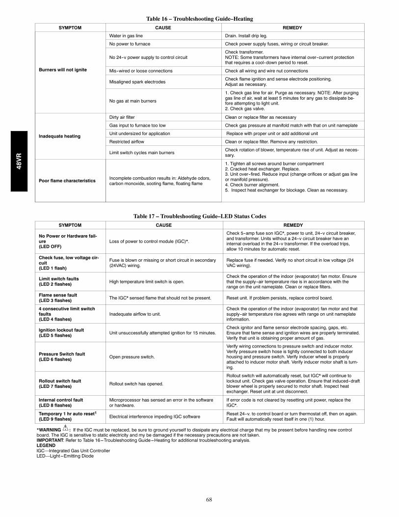
68
Table 16 – Troubleshooting Guide–Heating
SYMPTOM CAUSE REMEDY
Burners will not ignite
Water in gas line Drain. Install drip leg.
No power to furnace Check power supply fuses, wiring or circuit breaker.
No 24--v power supply to control circuitCheck transformer.NOTE: Some transformers have internal over--current protectionthat requires a cool--down period to reset.
Mis--wired or loose connections Check all wiring and wire nut connections
Misaligned spark electrodesCheck flame ignition and sense electrode positioning.Adjust as necessary.
No gas at main burners
1. Check gas line for air. Purge as necessary. NOTE: After purginggas line of air, wait at least 5 minutes for any gas to dissipate be-fore attempting to light unit.2. Check gas valve.
Inadequate heating
Dirty air filter Clean or replace filter as necessary
Gas input to furnace too low Check gas pressure at manifold match with that on unit nameplate
Unit undersized for application Replace with proper unit or add additional unit
Restricted airflow Clean or replace filter. Remove any restriction.
Limit switch cycles main burnersCheck rotation of blower, temperature rise of unit. Adjust as neces-sary.
Poor flame characteristics Incomplete combustion results in: Aldehyde odors,carbon monoxide, sooting flame, floating flame
1. Tighten all screws around burner compartment2. Cracked heat exchanger. Replace.3. Unit over--fired. Reduce input (change orifices or adjust gas lineor manifold pressure).4. Check burner alignment.5. Inspect heat exchanger for blockage. Clean as necessary.
Table 17 – Troubleshooting Guide–LED Status Codes
SYMPTOM CAUSE REMEDY
No Power or Hardware fail-ure(LED OFF)
Loss of power to control module (IGC)*.
Check 5--amp fuse son IGC*, power to unit, 24--v circuit breaker,and transformer. Units without a 24--v circuit breaker have aninternal overload in the 24--v transformer. If the overload trips,allow 10 minutes for automatic reset.
Check fuse, low voltage cir-cuit(LED 1 flash)
Fuse is blown or missing or short circuit in secondary(24VAC) wiring.
Replace fuse if needed. Verify no short circuit in low voltage (24VAC wiring).
Limit switch faults(LED 2 flashes) High temperature limit switch is open.
Check the operation of the indoor (evaporator) fan motor. Ensurethat the supply--air temperature rise is in accordance with therange on the unit nameplate. Clean or replace filters.
Flame sense fault(LED 3 flashes) The IGC* sensed flame that should not be present. Reset unit. If problem persists, replace control board.
4 consecutive limit switchfaults(LED 4 flashes)
Inadequate airflow to unit.Check the operation of the indoor (evaporator) fan motor and thatsupply--air temperature rise agrees with range on unit nameplateinformation.
Ignition lockout fault(LED 5 flashes) Unit unsuccessfully attempted ignition for 15 minutes.
Check ignitor and flame sensor electrode spacing, gaps, etc.Ensure that fame sense and ignition wires are properly terminated.Verify that unit is obtaining proper amount of gas.
Pressure Switch fault(LED 6 flashes) Open pressure switch.
Verify wiring connections to pressure switch and inducer motor.Verify pressure switch hose is tightly connected to both inducerhousing and pressure switch. Verify inducer wheel is properlyattached to inducer motor shaft. Verify inducer motor shaft is turn-ing.
Rollout switch fault(LED 7 flashes) Rollout switch has opened.
Rollout switch will automatically reset, but IGC* will continue tolockout unit. Check gas valve operation. Ensure that induced--draftblower wheel is properly secured to motor shaft. Inspect heatexchanger. Reset unit at unit disconnect.
Internal control fault(LED 8 flashes)
Microprocessor has sensed an error in the softwareor hardware.
If error code is not cleared by resetting unit power, replace theIGC*.
Temporary 1 hr auto reset1(LED 9 flashes) Electrical interference impeding IGC software
Reset 24--v. to control board or turn thermostat off, then on again.Fault will automatically reset itself in one (1) hour.
*WARNING : If the IGC must be replaced, be sure to ground yourself to dissipate any electrical charge that my be present before handling new controlboard. The IGC is sensitive to static electricity and my be damaged if the necessary precautions are not taken.IMPORTANT: Refer to Table 16---Troubleshooting Guide---Heating for additional troubleshooting analysis.LEGENDIGC—Integrated Gas Unit ControllerLED—Light---Emitting Diode
48VR
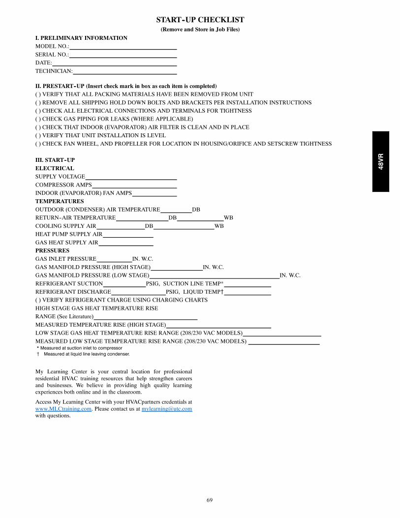
69
START--UP CHECKLIST(Remove and Store in Job Files)
I. PRELIMINARY INFORMATIONMODEL NO.:
SERIAL NO.:
DATE:
TECHNICIAN:
II. PRESTART--UP (Insert check mark in box as each item is completed)( ) VERIFY THAT ALL PACKING MATERIALS HAVE BEEN REMOVED FROM UNIT
( ) REMOVE ALL SHIPPING HOLD DOWN BOLTS AND BRACKETS PER INSTALLATION INSTRUCTIONS
( ) CHECK ALL ELECTRICAL CONNECTIONS AND TERMINALS FOR TIGHTNESS
( ) CHECK GAS PIPING FOR LEAKS (WHERE APPLICABLE)
( ) CHECK THAT INDOOR (EVAPORATOR) AIR FILTER IS CLEAN AND IN PLACE
( ) VERIFY THAT UNIT INSTALLATION IS LEVEL
( ) CHECK FAN WHEEL, AND PROPELLER FOR LOCATION IN HOUSING/ORIFICE AND SETSCREW TIGHTNESS
III. START--UPELECTRICALSUPPLY VOLTAGE
COMPRESSOR AMPS
INDOOR (EVAPORATOR) FAN AMPS
TEMPERATURESOUTDOOR (CONDENSER) AIR TEMPERATURE DB
RETURN--AIR TEMPERATURE DB WB
COOLING SUPPLY AIR DB WB
HEAT PUMP SUPPLY AIR
GAS HEAT SUPPLY AIR
PRESSURESGAS INLET PRESSURE IN. W.C.
GAS MANIFOLD PRESSURE (HIGH STAGE) IN. W.C.
GAS MANIFOLD PRESSURE (LOW STAGE) IN. W.C.
REFRIGERANT SUCTION PSIG, SUCTION LINE TEMP*
REFRIGERANT DISCHARGE PSIG, LIQUID TEMP{
( ) VERIFY REFRIGERANT CHARGE USING CHARGING CHARTS
HIGH STAGE GAS HEAT TEMPERATURE RISE
RANGE (See Literature)
MEASURED TEMPERATURE RISE (HIGH STAGE)
LOW STAGE GAS HEAT TEMPERATURE RISE RANGE (208/230 VAC MODELS)
MEASURED LOW STAGE TEMPERATURE RISE RANGE (208/230 VAC MODELS)* Measured at suction inlet to compressor{ Measured at liquid line leaving condenser.
My Learning Center is your central location for professionalresidential HVAC training resources that help strengthen careersand businesses. We believe in providing high quality learningexperiences both online and in the classroom.
Access My Learning Center with your HVACpartners credentials atwww.MLCtraining.com. Please contact us at [email protected] questions.
48VR
70
Copyright 2019 Carrier Corp. S 7310 W. Morris St. S Indianapolis, IN 46231 Edition Date: 08/19
Manufacturer reserves the right to change, at any time, specifications and designs without notice and without obligations.
Catalog No: 48VR---08SI
Replaces: 48VR---07SI
48VR