Embed Size (px)
Citation preview

Installation InstructionsPAD5 SeriesSingle Phase
PACKAGED AIR CONDITIONER UNITS
TABLEOF CONTENTS............................................... PAGESAFE INSTALLATION REQUIREMENTS ............ 2INTRODUCTION .................................. 2RECEIVING AND INSTALLATION ................... 2
Check Equipment ................................ 2Provide Unit Support ............................. 2
Ground Level Installation ......................... 2
Rooftop Installation .............................. 3Roof Curb ...................................... 3
Provide Clearances .............................. 3
Rig and Place Unit ............................... 3Inspection ...................................... 3Use of Rigging Bracket .......................... 3
Select and Install Duct Connections ................ 4
Configuring Discharge Units to Downftow(Vertical) Discharge Units ........................ 8
Connect Condensate Drain ....................... 8Install Electrical Connections ...................... 9
High-Voltage Connections ....................... 9Special Procedures for 208-V Operation ......... 10Control Voltage Connections .................... 10Standard Connections ......................... 10Transformer Protection ........................ 10
Accessory Electric Heater ...................... 10Sequence of Operation ........................ 10
PRE-START-UP ................................. 14START-UP ...................................... 14
Checking Cooling & Accessory Electric HeatOperation .................................... 14
Check for Refrigerant Leaks ...................... 14
Start-Up Adjustments .......................... 15Checking & Adjusting Refrigerant Charge ........ 15Indoor Airflow & Airflow Adjustments ............. 15Continuous Fan Operation ..................... 15
MAINTENANCE ................................. 17Air Filter ....................................... 17Indoor Blower and Motor ......................... 17Outdoor Coil, Indoor Coil, & Condensate Drain Pan . 19Outdoor Fan ................................... 20
Electrical Controls and Wiring .................... 20Refrigerant Circuit .............................. 20Indoor Airflow .................................. 20
Metering Device - Thermostatic Expansion Valve ... 20Pressure Switches .............................. 20
Loss of Charge Switch .......................... 20High Pressure Switch ........................... 20Copeland Scroll compressor (R-410A Refrigerant) .. 20Refrigerant System ............................. 21
Refrigerant ................................... 21Compressor Oil ............................... 21Servicing on Roofs with Synthetic Materials ....... 21Liquid Line Filter Drier ......................... 21R-410A Refrigerant Charging ................... 21
R-410A QUICK REFERENCE GUIDE .............. 22TROUBLESHOOTING ............................ 23START-UP CHECKLIST .......................... 24
InternationalComfort Products,LLCLewisburg,TN. 37091
519 01 1902 O0 04-27-09

SAFE INSTALLATION REQUIREMENTS
FIGURE 1 J PAD5 AIR CONDITIONING UNITt
Improper installation adjustment, alteration, service,maintenance, or use can cause explosion, fire, electricalshock, or other conditions which may cause death, personalinjury, or property damage. Consult a qualified installer,service agency, or your distributor or branch for informationor assistance. The qualified installer or agency must usefactory-authorized kits or accessories when modifying thisproduct Refer to the individual instructions packaged withthe kits or accessories when installing.
Follow all safety codes. Wear safety glasses, protectiveclothing, and work gloves. Use quenching cloth for brazingoperations. Have a fire extinguisher available. Read theseinstructions thoroughly and follow all warnings or cautionsincluded in literature and attached to the unit. Consult localbuilding codes, the current editions of the National ElectricalCode (NEC) NFPA 70.
In Canada refer to the current editions of the Canadianelectrical Code CSA C22.1.
Recogniz._ safety information. This is the safety-alertsymbol/.VX. When you see this symbol in instructions ormanuals, be alert to the potential for personal injury.
Understand the signal words DANGER, WARNING,CAUTION, and NOTE. These words are used with thesafety-alert symbol. DANGER identifies the most serioushazards which will result in serious injury or death.WARNING signifies a hazard which could result in seriousinjury or death. CAUTION is used to identify unsafepractices which may result in minor personal injury orproduct and property damage. NOTE is used to highlightsuggestions which will result in enhanced installation,reliability, or operation.
These instructions cover minimum requirements andconform to existing national standards and safety codes. Insome instances, these instructions exceed certain localcodes and ordinances, especially those that may not havekept up with changing residential construction practices. Werequire these instructions as a minimum for a safeinstallation.
ELECTRICAL SHOCK HAZARD
Failure to follow this warning could result in personal injury ordeath.
Before installingor servicing system, turn off power supply to theunit and install lockout tag. There may be more than onedisconnect switch. Turn off accessory heater power switch ifapplicable.
CUT HAZARD
Failure to follow this caution may result in personal injury.When removing access panels (see Fig. 18) or performingmaintenance functions inside your unit, be aware of sharpsheetmetal parts and screws.Although special care is taken toreduce sharp edges to aminimum, be extremely careful whenhandling parts or reaching into the unit.
INTRODUCTION
This packaged air conditioner unit is fully self-contained anddesigned for outdoor installation (see Fig. 1). See Fig. 3 and4 for unit dimensions. Standard units are shipped in ahorizontal-discharge configuration for installation on aground level slab. Standard units can be converted todownflow (vertical) discharge configurations for rooftopapplications.
RECEIVING AND INSTALLATION
Step 1reCheck Equipment
IDENTIFY UNIT
The unit model number and serial number are stamped onthe unit information plate. Check this information againstshipping papers.INSPECT SHIPMENT
Inspect for shipping damage before removing packagingmaterials. If unit appears to be damaged or is torn loose fromits anchorage, have it examined bytransportation inspectorsbefore removal. Forward claim papers directly totransportation company. Manufacturer is not responsible forany damage incurred in transit. Check all items againstshipping list. Immediately notify the nearest equipmentdistribution office if any item is missing. To prevent loss ordamage, leave all parts in original packages untilinstallation.
Step 2mProvide Unit Support
For hurricane tie downs, contact distributor for details andPE (Professional Engineering) Certificate if required.
Roof Curb
IMPORTANT: The unit must be secured to the curb byinstalling screws through the bottom of the curb flange andinto the unit base rails. When installing large base units ontothe common curb, the screws must be installed beforeallowing the full weight of the unit to rest on the curb. Aminimum of six screws are required for large base units.Failure to secure unit properly could result in an unstableunit. See Warning near Rigging/Lifting information andaccessory curb instructions for more details.
Install accessory roof curb in accordance with instructionsshipped with curb. See Fig. 5. Install insulation, cant strips,roofing, and flashing. Ductwork must be attached to curb.

IMPORTANT:Thegasketingoftheunittotheroofcurbiscriticalfor a watertight seal. Installgasketingmaterialsuppliedwiththe roofcurb.Improperlyappliedgasketingalsocanresultinairleaksandpoorunitperformance.Curbshouldbelevelto within%"(6mm)Thisisnecessaryfor unitdrainto functionproperly.Referto accessoryroofcurbinstallationinstructionsfor additionalinformationasrequired.Slab Mount
Place the unit on a solid, level concrete pad that is aminimum of 4" (102mm) thick with 2" (51mm) above grade(see Figure 2). The slab should extend approximately 2"beyond the casing on all 4 sides of the unit. Do not securethe unit to the slab except when required by local codes.
FIGURE 2 I Slab Mounting DetailsE
EVAR COIL COND. COIL
Step 3mProvide Clearances
The required minimum service clearances are shown in Fig.4 and 5. Adequate ventilation and outdoor air must beprovided. The outdoor fan draws air through the outdoor coiland discharges it through the top fan grille. Be sure that thefan discharge does not recirculate to the outdoor coil. Do notlocate the unit in either a corner or under an overhead
obstruction. The minimum clearance under a partialoverhang (such as a normal house overhang) is 48 in.(1219mm) above the unit top. The maximum horizontalextension of a partial overhang must not exceed 48in.(1219mm).
IMPORTANT: Do not restrict outdoor airflow. An air
restriction at either the outdoor-air inlet or the fan dischargemay be detrimental to compressor life.
Do not place the unit where water, ice, or snow from anoverhang or roof will damage or flood the unit. Do not installthe unit on carpeting or other combustible materials.Slab-mounted units should be at least 4 in. (102mm) abovethe highest expected water and runoff levels. Do not use unitif it has been under water.
Step 4mRig and Place Unit
Rigging and handling of this equipment can be hazardousfor many reasons due to the installation location (roofs,elevated structures, etc.).
Only trained, qualified crane operators and ground supportstaff should handle and install this equipment.
When working with this equipment, observe precautions inthe literature, on tags, stickers, and labels attached to the
equipment, and any other safety precautions that mightapply.
Training for operators of the lifting equipment shouldinclude, but not be limited to, the following:
1. Application ofthe lifter to the load, and adjustment ofthelifts to adapt to various sizes or kinds of loads.
2. Instruction in any special operation or precaution.
3. Condition of the load as it relates to operation of thelifting kit, such as balance, temperature, etc.
Follow all applicable safety codes. Wear safety shoes andwork gloves.INSPECTION
Prior to initial use, and at monthly intervals, all riggingshackles, clevis pins, and straps should be visuallyinspected for any damage, evidence of wear, structuraldeformation, or cracks. Particular attention should be paidto excessive wear at hoist hooking points and loadsupport areas. Materials showing any kind of wear inthese areas must not be used and should be discarded.
UNIT FALLING HAZARD
Failure to follow this warning could result in personalinjury or death.
Never stand beneath rigged units or lift over people.
Rigging/Lifting of Unit
UNIT FALLING HAZARD
Failure to follow this warning could result in personalinjury/death or property damage.
When straps are taut, the clevis should be a minimum of36 in. (914 mm) above the unit top cover.
UNIT FALLING HAZARD
Failure to follow this warning could result in personalinjury or death.
Large base units must be secured to common curbbefore allowingfull weight of unit to rest on curb. Installscrews through curb into unit base rails while riggingcrane is still supportingunit.
Lifting holes are provided in base rails as shown in Fig. 4and 5.
1. Leave top shipping skid on the unit for use as aspreader bar to prevent the rigging straps fromdamaging the unit. If the skid is not available, use aspreader bar of sufficient length to protect the unitfrom damage.
2. Attach shackles, clevis pins, and straps to the baserails of the unit. Be sure materials are rated to holdthe weight of the unit (See Fig. 3).
3. Attach a clevis of sufficient strength in the middle ofthe straps. Adjust the clevis location to ensure unit islifted level with the ground.
After the unit is placed on the roof curb or mounting pad,remove the top crating.
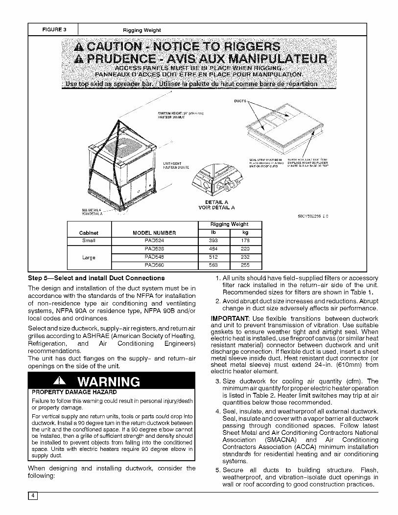
FIGURE 3 I Rigging Weight
JJ
JMINIMUM HEIGHT: 36" (9!4.4 turn)HAUTEUR MINIMUM
DUCTS
SEE DE,TAIL AVOIR DETAIL A
Cabinet
Small
Large
UNIT HEIGHT
HAUTEUR D'UNITE
DETAIL AVOIR DETAIL A
MODEL NUMBER
PAD524
PAD536
PAD548
PAD560
Rigging Weight
Ib kg
393 178
484 220
512 232
563 255
SEAL STRIP MUST BE IN
PLACE BEFORE PLACING
UNIT ON ROOF CURB
BANDE SCELLANT DOFf ETRE
EN PL/'tCE AVANT BE PLACER
L=UNITE SUR LA BASE DE TOW
50CY502286 2,0
Step 5_Select and Install Duct Connections
The design and installation of the duct system must be inaccordance with the standards of the NFPA for installationof non-residence type air conditioning and ventilatingsystems, NFPA 90A or residence type, NFPA 90B and/orlocal codes and ordinances.
Select and size ductwork, supply-air registers, and return airgrilles according to ASHRAE (American Society of Heating,Refrigeration, and Air Conditioning Engineers)recommendations.The unit has duct flanges on the supply- and return-airopenings on the side of the unit.
PROPERTY DAMAGE HAZARD
Failure to follow this warning could result in personal injury/deathor property damage.
For vertical supply and return units, tools or parts could drop intoductwork. Install a 90 degree turn in the return ductwork betweenthe unit and the conditioned space. If a 90 degree elbow cannotbe installed, then a grille of sufficient strength and density shouldbe installed to prevent objects from falling into the conditionedspace. Units with electric heaters require 90 degree elbow insupply duct.
When designing and installing ductwork, consider thefollowing:
1. All units should have field-supplied filters or accessoryfilter rack installed in the return-air side of the unit.Recommended sizes for filters are shown in Table 1.
2. Avoid abrupt duct size increases and reductions. Abruptchange in duct size adversely affects air performance.
IMPORTANT: Use flexible transitions between ductworkand unit to prevent transmission of vibration. Use suitablegaskets to ensure weather tight and airtight seal. Whenelectric heat is installed, use fireproof canvas (or similar heatresistant material) connector between ductwork and unitdischarge connection. If flexible duct is used, insert a sheetmetal sleeve inside duct. Heat resistant duct connector (orsheet metal sleeve) must extend 24-in. (610mm) fromelectric heater element.
3. Size ductwork for cooling air quantity (cfm). Theminimum air quantity for proper electric heater operationis listed in Table 2. Heater limit switches may trip at airquantities below those recommended.
4. Seal, insulate, and weatherproof all external ductwork.Seal, insulate and cover with avapor barrier all ductworkpassing through conditioned spaces. Follow latestSheet Metal and Air Conditioning Contractors NationalAssociation (SMACNA) and Air ConditioningContractors Association (ACCA) minimum installationstandards for residential heating and air conditioningsystems.
5. Secure all ducts to building structure. Flash,weatherproof, and vibration-isolate duct openings inwall or roof according to good construction practices.
141

z0Ii
i
z
zw
o
z
w
ii
o
o
t,---
o
e,l
_ :_ :"2 _ _ _2_ _2_ _ _
© o_ _ z ._
T
[] -I []
o
[]
t t
o
t_
.........5
X_
<<
LI.I
o
c_
co
oo
:s><>

wt,
f....
wt,wroJ
if....wr
o _,oJ
wr,
o
oooJoJ
o
o_o
i
io
€*qooo¢q
eo
_o
o _,_04 04
_o
co o
Lib ¢0 03
_o
o_
_oo
_ooo
_o_ _o o _ _ o_
o
{ iit°
n • 1
,6
_8 W
ao "I-(D
• "" ........................1
zAAS
o>
cO
oo_rbR-X:><::>_o

FIGURE 6 1 Roof Curb Dimensions
HVAC unit [_ HVAC unit
base ra_,.. _J basepan
_ealing
q_ "Gasket
_ moofcurb /Anchor screw _ _Wood nailer*
Flashing field _]
supplied _ :ilit_ Roofcurb*
::i:itl Insulation
]:: H/(field supplied)
Roofing material :[:i_
f,e,ds 00,ed--i!i II/
A09090
ROOF CURB DETAIL
COMMON CURB
Dashed lines show cross supportlocation for large basepan units.
A09096
F
SMALL
BASE
UNIT
/
LARGEBASEUNIT
LARGE CURB/
A09095
UNIT PLACEMENT ONCOMMON CURB
SMALL OR LARGE BASE UNIT
A09094
UNIT SIZE
24 - 60
36 - 60
NOTES:
CATALOGNUMBER
CPRFCURB010A00
CPRFCURB011A00
CPRFCURB012A00
CPRFCURB013A00
AIN. (mm)
11 (279)
14 (356)
11 (279)
14 (356)
B (small base) B (large base) C DIN. (mm)* IN. (mm)* IN. (mm) IN. (mm)
10 (254)
N/A
14 (356) 16 (406) 47.8 (!214)
E FIN. (mm) IN. (mm)
32.4 (822)
2.7 (69)
43.9 (!116)
1. Roof curb must be set up for unit being installed.
2. Seal strip must be applied, as required, to unit being installed.
3. Roof curb is made of 16-gauge steel.
4. Attach ductwork to curb (flanges of duct rest on curb).
5. Insulated panels: 1-in. (25 mm) thick fiberglass 1 lb. density.
6. When unit mounting screw is used (see Note A), a retainer bracket must be used as well. This bracket must also be used when required by code
for hurricane or seismic conditions. This bracket is available through Micrometl.

CONFIGURING UNITS FOR DOWNFLOW (VERTICAL)DISCHARGE
ELECTRICAL SHOCK HAZARD
Failure to follow this warning could result in personalinjury or death.Before installingor servicing system, turn off the powersupply to the unit and install lockout tag. There may bemore than one disconnect switch.
1. Open all electrical disconnects and install lockouttag before starting any service work.
2. Remove horizontal (metal) ductcovers to accessvertical (downflow) discharge duct knockouts in unitbasepan. (See Fig. 7.)
3. Starting in a corner as shown in Fig. 8, score thepanel in both directions from the corner. Tap thepanel out from the scored corner using a smallhammer. Be careful and not damage any other partof the unit.
4. If unit ductwork is to be attached to vertical openingflanges on the unit composite base (jackstandapplications only), do so at this time. Collect ALLscrews that were removed. Do not leave screws onrooftop as permanent damage to the roof may occur.
5. It is recommended that the unit base insulation
around the perimeter of the vertical return-airopening be secured to the unit base with aluminumtape. Applicable local codes may require aluminumtape to prevent exposed fiberglass.
6. Reinstall both horizontal duct covers. Ensureopening is air-and watertight.
7. After completing unit conversion, perform all safetychecks and power up unit.
NOTE:The design and installation of the duct system mustbe in accordance with the standards of the NFPA for
installation of nonresidence-type air conditioning andventilating systems, NFPA 90A or residence-type, NFPA90B; and/or local codes and ordinances.
Adhere to the following criteria when selecting, sizing, andinstalling the duct system:
1. Units are shipped for side shot installation.
2. Select and size ductwork, supply-air registers, andreturn-air grilles according to American Society ofHeating, Refrigeration and Air ConditioningEngineers (ASHRAE) recommendations.
3. Use flexible transition between rigid ductwork andunit to prevent transmission of vibration. Thetransition may be screwed or bolted to duct flanges.Use suitable gaskets to ensure weather-tight andairtight seal.
4. All units must have field-supplied filters oraccessory filter rack installed in the return-air side ofthe unit. Recommended sizes for filters are shown inTable 1.
5. Size all ductwork for maximum required airflow(either heating or cooling) for unit being installed.Avoid abrupt duct size increases or decreases or
performance may be affected.
6. Adequately insulate and weatherproof all ductworklocated outdoors. Insulate ducts passing throughunconditioned space, and use vapor barrier inaccordance with latest issue of Sheet Metal and AirConditioning Contractors National Association(SMACNA) and Air Conditioning Contractors ofAmerica (ACCA) minimum installation standards forheating and air conditioning systems. Secure allducts to building structure.
7. Flash, weatherproof, and vibration-isolate allopenings in building structure in accordance withlocal codes and good building practices.
FIGURE 7 Supply and Return Duct Openings
Horizontai Duct Coors
BasepanDewnl_
Kllock_t
FIGURE 8 Vertical (Downflow) Discharge Duct Knockouts
INSTRUCTIONS FOR REMOVING DOWNSHOT PANELS
1. Score grove in corner I in both directions as far as you can reach.
2. Starting in corner 1, tap-out aft sides with a smafl hammer. Be careful
not to damage any other part of unit.
3. If side from corner 3 to 4 is not accessible due to heat exchanger,pivot panel up and down by hand until remaining side breaks off.
Step 6 1 Provide for Condensate Disposal
NOTE:Ensure that condensate-water disposal methodscomply with local codes, restrictions, and practices.

The PAD5unitsdisposeof condensatethrougha 3/4 in.NPTfemalefittingthatexitsonthecompressorendoftheunit.Condensatewatercanbedraineddirectlyontotheroof in rooftopinstallations(wherepermitted)or ontoagravel apron in ground level installations.Install afield-suppliedcondensatetrap at end of condensateconnectionto ensureproperdrainage.Makesurethattheoutletof thetrapis at least1 in. (25mm)lowerthanthedrain-pancondensateconnectionto preventthepanfromoverflowing.Primethe trap with water.Whenusingagravelapron,makesureit slopesawayfromtheunit.If the installationrequiresdrainingthecondensatewaterawayfromthe unit,installa field-supplied2 -in. (51mm)trap at the condensateconnectionto ensureproperdrainage.Condensatetrapisavailableasanaccessoryoris field-supplied.Makesurethattheoutletofthetrapisatleast 1 in. (25 mm) lower than the unit drain-pancondensateconnectionto prevent the pan fromoverflowing.Connecta draintubeusinga minimumoffield-supplied3/4-in. PVC or field-supplied3/4-in.copperpipeat outletendofthe2-in. (51mm)trap.(SeeFig.9) Donot undersizethe tube.Pitchthe draintubedownwardat a slopeof at least1 in. (25mm)every10ft(3m)of horizontalrun.Besureto checkthedraintroughfor leaks.Primethe trapat the beginningof the coolingseasonstart-up.
FIGURE 9 Condensate Trap
lqn. (25 ram) rain.
TRAP
OUTLET
..... i
----4
2qn. (51 ram) rain.
FIGURE 10 Unit Levelin_l Tolerances
M
[3ALLOWABLE
DIFFERENCE in, (mm)
B-C A CAB
1/4 (6.35) 1/4 (6.35) 1/4 (6.35)
Step 7reinstall Electrical Connections
UNIT COMPONENT DAMAGE HAZARD
Failure to follow this caution may result in damage to theunit being installed.
1. Make all electrical connections in accordance with
NEC ANSI/NFPA (latest edition) and local electricalcodes governing such wiring. In Canada, allelectrical connections must be in accordance withCSA standard C22.1 Canadian Electrical Code Part
1 and applicable local codes. Refer to unit wiringdiagram.
2. Use only copper conductor for connections betweenfield-supplied electrical disconnect switch and unit.DO NOT USE ALUMINUM WIRE.
3. Be sure that high-voltage power to unit is withinoperating voltage range indicated on unit ratingplate.
4. Do not damage internal components when drillingthrough any panel to mount electrical hardware,conduit, etc.
HIGH-VOLTAGE CONNECTIONS
ELECTRICAL SHOCK HAZARD
Failure to follow this warning could result in personalinjury or death.
Before making any wiring changes, switch off the mainpower supply to the unit and install lockout tag.
The unit must have a separate electrical service with afield-supplied, waterproof disconnect switch mounted at, orwithin sight from the unit. Refer to the unit rating plate, NECand local codes for maximum fuse/circuit breaker size andminimum circuit amps (ampacity) for wire sizing.
The field-supplied disconnect switch box may be mountedon the unit over the high-voltage inlet hole when thestandard power and low-voltage entry points are used (SeeFig. 4 and 5 for acceptable location). Remove the highvoltage knockout.
See unit wiring label, Fig. 11 and Fig. 12, for reference whenmaking high voltage connections. Proceed as follows tocomplete the high -voltage connections to the unit.
ELECTRICAL SHOCK HAZARD
Failure to follow this warning could result in personalinjury or death.
The unit cabinet must have an uninterrupted, unbrokenelectrical ground. This ground may consist of anelectrical wire connected to the unit ground screw in thecontrol compartment, or conduit approved for electricalground when installed in accordance with NEC,ANSI/NFPA American National StandardsInstitute/National Fire Protection Association (latestedition) (in Canada, Canadian Electrical Code CSAC22.1) and local electrical codes.

FIGURE 11 High and Control Voltage Connections
HIGH VOLTAGE
OWE 'EAO (SEE UNIT WIRING
LABEL)
1-PHASEUSES
TWO POWER
LEADS EQUIP GR
CONTROLBOX
LOW - VOLTAGE
POWER LEADS
(SEE UNIT
WIRING LABEL)
I
q_.---
O-----
\
SPLICE BOX
!__f_l POWER
SUPPLY
FIELD-SUPPLIED
FUSED DISCONNECT
WHT (W2) {__
vlo (w3){)_
YEL (Y1)
PNK(Y2)D-
GRN (G) .[_
RED (R)
BRN (C)
@@@.@©.@©
o
'E
I--
Single phase units:
1. Run the high-voltage (L1, L2) and ground lead into thecontrol box.
2. Connect ground lead to chassis ground connection.
3. Locate the black and yellow wires connected to the lineside of the contactor.
4. Connect field L1 to black wire on connection 11 of thecompressor contactor.
5. Connect field wire L2 to yellow wire on connection 23 ofthe compressor contactor.
SPECIAL PROCEDURES FOR 208-V OPERATION
ELECTRICAL SHOCK HAZARD
Failure to follow this warning could result in personalinjury or death.
Before making any wiring changes, switch off the mainpower supply to the unit. Tag the disconnect switch witha suitable warning label. With disconnect switch open,move black wire from transformer (3/16 in.) terminalmarked 230 to terminal marked 208. This retapstransformer to primary voltage of 208 vac.
CONTROL VOLTAGE CONNECTIONS
NOTE: Do not use any type of power-stealing thermostat.Unit control problems may result.
Use no. 18 American Wire Gage (AWG) color-coded,insulated (35°C minimum) wires to make the control voltageconnections between the thermostat and the unit. If the
thermostat is located more than 100 ft (30.5 m) from the unit(as measured along the control voltage wires), use no. 16AWG color-coded, insulated (35°C minimum) wires.STANDARD CONNECTIONS
Locate the seven low voltage thermostat leads in 24 voltsplice box. See figure 11 for connection diagram. Run thelow-voltage leads from the thermostat, through the control
1101
wiring inlet hole grommet, (Fig. 4 and 5), and into thelow-voltage splice box. Provide a drip loop before runningwires through panel. Secure and strain relief all wires so thatthey do not interfere with operation of unit.
If an accessory electric heater is installed, low voltage leadsfrom heater must be connected to factory supplied controlleads from Indoor Fan Board P4 connector. Factory wiresare provided for electric heat staging W2 and W3 (Pleasenote that some thermostats are marked "Wl" and "W2" forfirst and second stage electric heat, respectively). If roomthermostat has only one stage of supplemental heat,connect white and violet wires shown in figure 10 to secondstage heat field wire.
Some electric heaters have four control wires (plus commonwire). Consult unit wiring diagram and electric heater wiringdiagram for additional details.
TRANSFORMER PROTECTION
The transformer is of the energy-limiting type. It is set towithstand a 30-second overload or shorted secondarycondition. If an overload or short is present, correct overloadcondition and check for blown fuse on control board.Replace fuse as required with correct size and rating.
ACCESSORY ELECTRIC HEATER
Electric heaters may be installed per instructions suppliedwith electric heater package. See unit rating plate forfactory-approved electric heater kits.
SEQUENCE OF OPERATION
a. CONTINUOUS FAN
(1.) Thermostat closes circuit R to G energizing theblower motor for continuous fan. The indoor fanis energized on low speed.
b. COOLING MODE
(1.) Low Stage: Thermostat closes R to G, R to Y1.The compressor and indoor fan are energizedon low speed. The outdoor fan is alsoenergized.
(2.) High Stage: Thermostat closes R to G, R to Y1,R to Y2. The compressor and indoor fan areenergized on high speed. The outdoor fan isalso energized.
c. ELECTRIC HEATING MODE(1.) Thermostat closes circuit R to W2 or W3,and R to G. There are no on or off delays.

Table lmPhysical Data - Unit PAD5UNIT SIZE PAD524 PAD536 PAD548 PAD560
NOMINAL CAPACITY (ton) 2 3 4 5
SHIPPING WEIGHT Ib (kg) 393 (178) 484 (220) 512 (232) 563 (255)COMPRESSOR TYPE TWO STAGE SCROLL COMPRESSOR
Refrigerant (R-410A) Quantity Ib 10.t 9.5 15.3 15.8Quantity (kg) (4.6) (4.3) (6.9) (7.2)
REFRIGERANT METERING DEVICE TXV
SIZE 2 TON 3 TON 4 TON 5 TON
PART NUMBER EA36YD 129 EA36YD 139 EA36YD 149 EA36YD 159
OUTDOOR COILRows,,, Fins/in, 2...21 2...21 2...21 2...21
face area (sq. ft,) 13.6 17.5 19.4 23.3
OUTDOOR FAN 2700 2800 3300 3300
Nominal Airflow (CFM) 22 22 22 221/8 (825) 1/8 (825) 1/4 (1100) 1/3 (1110)
3...t7 3...17 3...17 4...173.7 4.7 5.7 5.7
Diameter Motor HP (RPM)
INDOOR COILRows... Fins/in.face area (sq. ft.)
INDOOR BLOWER
Nominal Low Stage Cooling Airflow (CFM)Nominal Low Stage Cooling Airflow (CFM)Blower Wheel Size in. x in. (mm)
(mm x mm)Motor (HP)
HIGH-PRESSURE SWITCH (psig)Cutout
Reset (Auto)
HIGH-PRESSURE SWITCH 2 (psig)Compressor SolenoidCutout
Reset (Auto)
LOSS-OF-CHARGE/LOW-PRESSURE SWITCH
(Liquid Line) (psig)Cutout
Reset (Auto)
RETURN-AIR FILTERS* Throwaway in.(mm)
600800
10x10(254x254)
1/2
8501200
11x10(279x254)
3/4
1100160011x10
(279x254)1.0
670_+10470_+25
565_+15455_+15
23_+555_+5
20x24x1 24x30x1 24x36x1
(508x610x25) (610x762x25) (610x914x25)
1200175011x10
(279x254)1.0
* Recommended filter sizes for field-installed air filter grilles mounted on the wall or ceiling of the conditioned structure. Required filter sizes shown arebased on the ARI (Air conditioning and Refrigeration Institute) rated high stage cooling airflow and a maximum face velocity of 300 ft/minute forthrowaway type or 450 ft/minute for permanent filters. Air filter pressure drop for non-standard filters must not exceed 0.08 IN. W.C.
Table 2mMinirnurn Airflow for Reliable Electric Heater Operation (CFM)
size I PAD524 I PAD536 I PAD54e I PAD560AIRFLOW (CFM) l 800 i 1200 i 1600 i 1750
il
Illl

FIGURE 12 CONNECTION WIRING DIAGRAM FOR PAD5, 2 to 5 Ton Units
CONNECTION WIRING DIAGRAM
DANGER ELECTRICAL SttOCK //AZARD DISCONNECT POWER
BLK
YEL
H
BEFORE SERVICINGSCHEMATIC
USED 208/230V-1-60
OFM
COMP SOLENOID
T-STAT
G
R RED --
YI YEL
W2 --WHT --
UNIT COMPONENT ARRANGEMENI
OUIDOOR FANSECTION
COMPRESSORSECIION
Y2 --PN}_ --
W3vzo --
C--BRN
INDOOR FAN CONTROLBOX AREASECTION
IFB
LEGEND
_FIELD SPLICE cCAR CAPACI[oRCONTACTORCDTERMINAL CMARNED)
o TERW!RAL (UNNARKED) CN CIRCUIT BREAKERCCR CRANK CASE REATER
o SPLICE CONP COMPRESSOR WOTOR
D SPLICE _ARNED_ CTD COWPRERSOR TIME RELAY
..............FACTORY WIRING FCB FAN CONTROL ROARD
--FIELD CONTROL WIRING GND GROUND
--- FIELD POWER W!RING HPS RIDR PRESGUR£ DWITCR
ACCRSSORY OR OPTIONAL RR REATER RELAY
WIRING IFD INDOOR FAN BOARD
--[0 !ND!CA[E COWWON ]FW INDOOR RAN MOTOR
POTENTIAL ONLY: LPS LOW PRESSURE SWITCH
ROT TO REPRESENT WIRING O_W OR[DOOR FAN NOFOR
TRAM IRANSFORRER
T_STAT TRERNOSTAT
NOTES:
IT MDST BE REPLACED WITH TYPE 90 DEGREE C WIRE OR
IT'S EQUIVALENT.
......... 2= SEE PRICE RAGES FOR YHERNOSYAT AND SUDBASRSi USE 75 DEGREE COPPER CONDUCTORS FOR FIELD INSTALLATION.
4 DEFROST TIMER TO BE SET AT 60 MIN.
R4V POWER S SEE INSTALLATION INSTRUCTIONS FOR PROPER HEATING ARD COOLINGENTRY CONNECIEONS FOR YOUR UNIT INDOOR FAN PLUGS -"DO NOT DISCONNECt
UNDER LOAD. I1
_, 'IDO _OT DISCONNECT PLUG UNDER LOAD,
7 UDRN ON 024 AND 060 UNITS ONLY,8[ IRIS DUDE IS _ANUFACIURED BY L!TTLEFUSE, PIN ZGl_03.
RED
+BLK
ACC[SSSORY ELECTRIC N[AT_
HR1 (5 RW)__BRNWNT -- BRN--
HRI,R,3 A 4 (NO KWh.....

Figure 11 Cont. LADDER WIRING DIAGRAM FOR PAD5, 2 to 5 Ton Units
lADDER WIRING DIAGRAM
DANGER ELECTRICAL SktOCK IIAZARD DISCONNECT PQWSR BEFORE SERVICING
T "STAT
R -
C _ z_ BRN-
Y1-
G-
Y2-
W2
W3-
L1 IL2YEI
11
11
11
IFB
SEE FUSENOTE 8OF_x{
3 AMP
......OPl 1"R"
<DPl 2"c"
_P1 3"Y!"
XD P! 4"6"
0 m-s"Y2"
42)m-6"w2"
-0 Pl 7"W3"
"v" C--
P2 1 'C'IC
P2-2.y,, C
LOWC
II USE COPPER CONDUCTORS ONLY EQUIP GND
BLK FIELD SUPPLY208/230 VAC, 60 HZ, PH .........
C 21 23
--H BLK _BL (_21 BLK f iM_'"
IF
BLK
Q YEb '
BLK _G/Y_7 YEL-
24VAC/R
250 TRAN CON208
P4-S'W3" C
24V " 77L7G/y
YEb
C 25
23
IFB
)IFB CONHPS1 LPS
_RN
--YEI ....
-WHT
-RED
SEE NOTE 5,IFB C
HPS2
SOLENOID
TO ACCESSORYELEC [R!C HEAl
50EZSO0 59
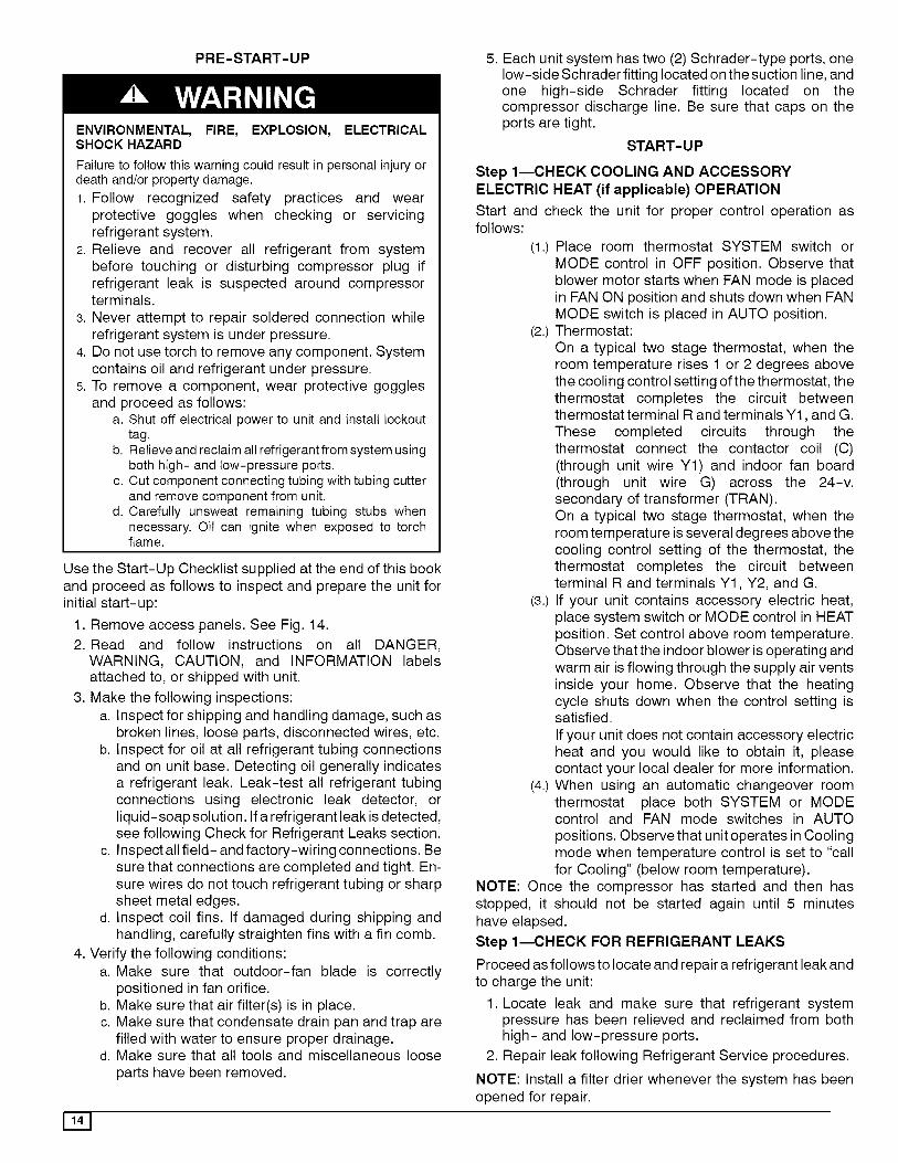
PRE-START-UP
ENVIRONMENTAL, FIRE, EXPLOSION, ELECTRICALSHOCK HAZARD
Failureto follow this warning could result in personal injury ordeath and/or property damage.1. Follow recognized safety practices and wear
protective goggles when checking or servicingrefrigerant system.
2. Relieve and recover all refrigerant from systembefore touching or disturbing compressor plug ifrefrigerant leak is suspected around compressorterminals.
3. Never attempt to repair soldered connection whilerefrigerant system is under pressure.
4. Do not use torch to remove any component. Systemcontains oil and refrigerant under pressure.
5. To remove a component, wear protective gogglesand proceed as follows:
a. Shut off electrical power to unit and install lockouttag.
b. Relieveand reclaimall refrigerantfrom system usingboth high- and low-pressure ports.
c. Cut component connecting tubing with tubing cutterand remove component from unit.
d. Carefully unsweat remaining tubing stubs whennecessary. Oil can ignite when exposed to torchflame.
Use the Start-Up Checklist supplied at the end of this bookand proceed as follows to inspect and prepare the unit forinitial start-up:
1. Remove access panels. See Fig. 14.2. Read and follow instructions on all DANGER,
WARNING, CAUTION, and INFORMATION labelsattached to, or shipped with unit.
3. Make the following inspections:a. Inspect for shipping and handling damage, such as
broken lines, loose parts, disconnected wires, etc.b. Inspect for oil at all refrigerant tubing connections
and on unit base. Detecting oil generally indicatesa refrigerant leak. Leak-test all refrigerant tubingconnections using electronic leak detector, orliquid-soap solution. If a refrigerant leak is detected,see following Check for Refrigerant Leaks section.
c. Inspect all field- and factory-wiring connections. Besure that connections are completed and tight. En-sure wires do not touch refrigerant tubing or sharpsheet metal edges.
d. Inspect coil fins. If damaged during shipping andhandling, carefully straighten fins with a fin comb.
4. Verify the following conditions:a. Make sure that outdoor-fan blade is correctly
positioned in fan orifice.b. Make sure that air filter(s) is in place.c. Make sure that condensate drain pan and trap are
filled with water to ensure proper drainage.d. Make sure that all tools and miscellaneous loose
parts have been removed.
1141
5. Each unit system has two (2) Schrader-type ports, onelow-side Schrader fitting located on the suction line, andone high-side Schrader fitting located on thecompressor discharge line. Be sure that caps on theports are tight.
START- UP
Step 1reCHECK COOLING AND ACCESSORYELECTRIC HEAT (if applicable) OPERATION
Start and check the unit for proper control operation asfollows:
(1.) Place room thermostat SYSTEM switch orMODE control in OFF position. Observe thatblower motor starts when FAN mode is placedin FAN ON position and shuts down when FANMODE switch is placed in AUTO position.
(2.) Thermostat:On a typical two stage thermostat, when theroom temperature rises 1 or 2 degrees abovethe cooling control setting of the thermostat, thethermostat completes the circuit betweenthermostat terminal R and terminals Y1, and G.These completed circuits through thethermostat connect the contactor coil (C)(through unit wire Y1) and indoor fan board(through unit wire G) across the 24-v.secondary of transformer (TRAN).On a typical two stage thermostat, when theroom temperature is several degrees above thecooling control setting of the thermostat, thethermostat completes the circuit betweenterminal R and terminals Y1, Y2, and G.
(3.) If your unit contains accessory electric heat,place system switch or MODE control in HEATposition. Set control above room temperature.Observe that the indoor blower is operating andwarm air is flowing through the supply air ventsinside your home. Observe that the heatingcycle shuts down when the control setting issatisfied.If your unit does not contain accessory electricheat and you would like to obtain it, pleasecontact your local dealer for more information.
(4.) When using an automatic changeover roomthermostat place both SYSTEM or MODEcontrol and FAN mode switches in AUTOpositions. Observe that unit operates in Coolingmode when temperature control is set to "callfor Cooling" (below room temperature).
NOTE: Once the compressor has started and then hasstopped, it should not be started again until 5 minuteshave elapsed.
Step 1reCHECK FOR REFRIGERANT LEAKS
Proceed as follows to locate and repair a refrigerant leak andto charge the unit:
1. Locate leak and make sure that refrigerant systempressure has been relieved and reclaimed from bothhigh- and low-pressure ports.
2. Repair leak following Refrigerant Service procedures.
NOTE: Install a filter drier whenever the system has beenopened for repair.

3.Adda smallchargeof R-410Arefrigerantvaportosystemandleak-testunit.
4. Recoverrefrigerantfrom refrigerantsystem andevacuateto500micronsifnoadditionalleaksarefound.
5.ChargeunitwithR-410Arefrigerant,usinganelectronicscale.Refertounitratingplateforrequiredcharge.
STEP 2reSTART-UP ADJUSTMENTS
Complete the required procedures given in thePre-Start-Up section before starting the unit. Do not jumperany safety devices when operating the unit. Do not operatethe unit in cooling mode when the outdoor temperature isbelow 40°F (4°C) (unless accessory low-ambient kit isinstalled).
Checking and Adjusting Refrigerant Charge
The refrigerant system is fully charged with R-410Arefrigerant and is tested and factory sealed.
NOTE: Adjustment of the refrigerant charge is notrequired unless the unit is suspected of not having theproper R-410A charge.
A subcooling charging chart is attached to the inside ofthe compressor access panel. The chart includes therequired liquid line temperature at given discharge linepressures and outdoor ambient temperatures.An accurate thermocouple- or thermistor-typethermometer, and a gauge manifold are required whenusing the subcooling charging method for evaluating theunit charge. Do not use mercury or small dial-typethermometers because they are not adequate for this typeof measurement.
NOTE: Allow system to operate on high stage cooling fora minimum of 15 minutes before checking or adjustingrefrigerant charge.
IMPORTANT: When evaluating the refrigerant charge, anindicated adjustment to the specified factory charge mustalways be very minimal. If a substantial adjustment isindicated, an abnormal condition exists somewhere in thecooling system, such as insufficient airflow across eithercoil or both coils.
1. Remove caps from low- and high-pressure servicefittings.
2. Using hoses with valve core depressors, attach low-and high-pressure gauge hoses to low- andhigh-pressure service fittings, respectively.
3. Start unit and let run until system pressures stabilize.
4. Measure and record the following:a. Outdoor ambient-air temperature (°F [°C] db).b. Liquid line temperature (°F [°C]) at TXV.c. Discharge (high-side) pressure (psig).d. Suction (low-side) pressure (psig) (for reference
only).5. Using Cooling Charging Charts compare outdoor-air
temperature (°F [°C] db) with the discharge linepressure (psig) to determine desired system operatingliquid line temperature (See Fig. 14).
6. Compare actual liquid line temperature with desiredliquid line temperature. Using a tolerance of _+2°F(_+1.1°C), add refrigerant if actual temperature is morethan 2°F (1.1°C) higher than proper liquid linetemperature, or remove refrigerant if actual temperature
is more than 2°F (1.1 °C) lower than required liquid linetemperature.
NOTE: If the problem causing the inaccurate readings is arefrigerant leak, refer to Check for Refrigerant Leakssection.
Indoor Airflow and Airflow Adjustments
UNIT OPERATION HAZARD
Failure to follow this caution may result in unitdamage.
For cooling operation, the recommended airflow is 350to 450 cfm for each 12,000 Btuh of rated coolingcapacity. For heating operation, the airflow mustproduce a temperature rise that falls within the rangestamped on the unit rating plate.
All blower motors are factory wired for nominal high stageand low stage cooling airflow operation at minimumexternal static pressure. See Table 1.
NOTE: Be sure that all supply- and return-air grilles areopen, free from obstructions, and adjusted properly.
Table 3mColor Coding for Indoor Fan Motor LeadsBlack = High Speed
Orange = Med-High SpeedRed = Med Speed
Pink = Med-Low SpeedBlue = Low Speed
ELECTRICAL SHOCK HAZARD
Failure to follow this warning could result in personalinjury or death.
Disconnect electrical power to the unit and installlockout tag before changing blower speed.
The high stage cooling fan speed of the unit is connectedto the "HIGH" terminal on the interface fan board (IFB)(See Fig. 13). The low stage cooling fan speed of the unitis connected to the "LOW" terminal on the interface fan
board (IFB) (See Fig. 13). The unit is factory-shipped withfan speeds as noted in Table 4. There are 3 additionalspeed tap wires available for use (For color coding on theindoor fan motor leads, see Table 3). The additional 3speed tap wires are shipped loose with vinyl caps and arelocated in the control box, near the IFB.
To change the fan speed, remove the vinyl cap off of thedesired speed tap wire (Refer to Table 3 for color coding).Remove the current speed tap wire from the "HIGH" or"LOW" terminal on the interface fan board (IFB) (Fig. 13)and place vinyl cap over the connector on the wire.Connect the desired speed tap wire to the "HIGH" or"LOW" terminal on the IFB. For optimum performance,add the wet coil pressure drop in Table 5 to the systemstatic to determine the correct cooling airflow speed inTable 4 that will deliver the nominal cooling airflow aslisted in Table 1 for each size.
NOTE: For cooling operation, the recommended airflow is350 to 450 CFM for each 12,000 Btuh of rated coolingcapacity.
1151

NOTE: If accessory electric heat is installed in the unit, thedry airflow must meet or exceed the minimum airflowspecified in Table 2 for the specific size. Use Table 4 todetermine dry airflow for a known external static pressure.Electric heat fan speed is the same as high stage coolingfan speed.
FIGURE 13 I Interface Fan BoardI
agci
c_J%
Continuous Fan Operation
The continuous fan operates at the same fan speed aslow stage cooling fan operation.
HI6HQC5
142 KI
D7 D9 DIO DB RIO RI5 08 RII F_ D2 0
G9 RI DI _
DII Z2 D6 Da- " _'?
3
q3
SS2-0 IA
IEAOI6 _3 W272 8 Y1 C R
8W5 R3 RS R&R2
QC8
OEy R W2 Y C
FIGURE 14 Unit Access Panels
FilterAccessPanel
1161

MAINTENANCE
To ensure continuing high performance, and to minimizethe possibility of premature equipment failure, periodicmaintenance must be performed on this equipment. Thisheat pump unit should be inspected at least once eachyear by a qualified service person. To troubleshoot unit,refer to Table 8.
NOTE:TO EQUIPMENT OWNER: Consult your localdealer about the availability of a maintenance contract.
PERSONAL INJURY AND UNIT DAMAGE HAZARD
Failure to follow this warning could result in personal injuryor death and unit component damage.
The ability to properly perform maintenance on thisequipment requires certain expertise, mechanical skills,tools and equipment. If you do not possess these, do notattempt to perform any maintenance on this equipment,other than those procedures recommended in the Owner'sManual.
ELECTRICAL SHOCK HAZARD
Failure to follow these warnings could result in personalinjury or death:
1. Turn off electrical power to the unit and install a
lockout tag before performing any maintenance orservice on this unit.
2. Use extreme caution when removing panels and
parts.
3. Never place anything combustible either on or incontact with the unit.
UNIT OPERATION HAZARD
Failure to follow this caution may result in improperoperation.
Errors made when reconnecting wires may causeimproper and dangerous operation. Label all wires priorto disconnecting when servicing.
The minimum maintenance requirements for thisequipment are as follows:
1. Inspect air filter(s) each month. Clean or replace whennecessary.
2. Inspect indoor coil, drain pan, and condensate draineach cooling season for cleanliness. Clean whennecessary.
3. Inspect blower motor and wheel for cleanliness eachcooling season. Clean when necessary.
4. Check electrical connections for tightness and controlsfor proper operation each cooling season. Service whennecessary.
5. Ensure electric wires are not in contact with refrigeranttubing or sharp metal edges.
Step 1 m Air FilterIMPORTANT:Never operate the unit without a suitable airfilter in the return-air duct system. Always replace the
filter with the same dimensional size and type as originallyinstalled. See Table 1 for recommended filter sizes.
Inspect air filter(s) at least once each month and replace(throwaway-type) or clean (cleanable-type) at least twiceduring each cooling season and twice during the heatingseason, or whenever the filter becomes clogged with dustand lint.Indoor Blower and Motor
NOTE: All motors are pre-lubricated. Do not attempt tolubricate these motors.
For longer life, operating economy, and continuingefficiency, clean accumulated dirt and grease from theblower wheel and motor annually.
ELECTRICALSHOCK HAZARD
Failure to follow this warning could result in personalinjury or death.Disconnect and tag electrical power to the unit beforecleaning the blower motorand wheel.
To clean the blower motor and wheel:
1. Remove and disassemble blower assembly as follows:
a. Remove blower access panel. See Fig. 14.b. Disconnect 5 pin plug and 4 pin plug from indoor
blower motor.
c. On all units remove blower assembly from unit.Remove screws securing blower to blowerpartition and slide assembly out. Be careful not totear insulation in blower compartment.
d. Ensure proper reassembly by marking blowerwheel and motor in relation to blower housingbefore disassembly.
e. Loosen setscrew(s) that secures wheel to motorshaft, remove screws that secure motor mountbrackets to housing, and slide motor and motormount out of housing.
2. Remove and clean blower wheel as follows:
a. Ensure proper reassembly by marking wheelorientation.
b. Lift wheel from housing. When handling and/orcleaning blower wheel, be sure not to disturbbalance weights (clips) on blower wheel vanes.
c. Remove caked-on dirt from wheel and housingwith a brush. Remove lint and/or dirtaccumulations from wheel and housing withvacuum cleaner, using soft brush attachment.Remove grease and oil with mild solvent.
d. Reassemble wheel into housing.e. Reassemble motor into housing. Be sure
setscrews are tightened on motor shaft flats andnot on round part of shaft.
£ Connect 5 pin plug and 4 pin plug to indoorblower motor.
g. Reinstall blower access panel.
3. Restore electrical power to unit. Start unit and check forproper blower rotation and motor speeds during coolingcycles.

Unit
(Voltage)
PAD524(208/230-1-60)
PAD536
(208/230-1-60)
PAD548(208/230-1-60)
PAD560(208/230-1-60)
Table 4--DryMotor
SpeedLow 1
Med-LowMedium 2
Med-HighHighLow 1
Med-LowMedium
Med-High 2HighLow 1
Med-LowMedium 2
Med-HighHigh
Low 1Med-LowMedium 2
Med-HighHigh
Coil Air Delivery* - Horizontal and Downflow Discharge - Unit PAD5Wire External Static Pressure (IN. W.C.)ColorBluePinkRed
OrangeBlackBluePinkRed
OrangeBlackBluePinkRed
OrangeBlackBluePinkRed
OrangeBlack
0.1 0.2 0.3 0.4 0.5 0.6 0.7 0.8 0.9CFM 659 551 440 335 ...............CFM 726 625 537 407 ...............CFM 907 837 759 679 588 474 343 ......CFM 953 870 807 718 652 528 443 ......CFM 1179 1118 1061 996 942 864 794 718 619CFM 921 740 448 ..................CFM 1019 849 603 479 ...............CFM 1272 1203 1150 1097 1054 996 937 881 841CFM 1321 1258 1212 1168 1114 1075 1009 856 904CFM 1478 1426 1387 1334 1292 1247 1212 1148 1108CFM 1201 1159 1101 1062 1004 957 897 852 793CFM 1419 1364 1318 1258 1214 1160 1118 1053 1009CFM 1678 1635 1602 1558 1513 1474 1438 1404 1349CFM 1916 1881 1846 1810 1761 1722 1681 1647 1600CFM 2093 2051 2024 1967 1947 1907 1854 1826 1749CFM 1320 1256 1211 1142 1096 1028 973 903 835CFM 1351 1295 1258 1212 1170 1124 1080 1036 992CFM 1824 1782 1742 1711 1673 1641 1607 1563 1490CFM 2001 1958 1923 1883 1831 1776 1705 1624 1538CFM 2292 2238 2158 2049 1935 1840 1732 1635 1513
Air delivery values are without air filter and are for dry coil (SeeFactory-shipped low stage cooling speedFactory-shipped high stage cooling speed, Electric heat speed
NOTE: Deduct field-supplied air filter pressure drop and wet coil
PAD5 Wet Coil Pressure Drop Table).
(If electric heat is installed).
pressure drop to obtain external static pressure available for ducting.
Table 5_PAD5 Wet Coil Pressure Drop (in. W.C.)UNIT STANDARDCFM(S.C.RM)SIZE 600 700 800 900 1000 1100 1200 1300 1400 1500 1600 1700 1800 1900 2000 2100
24 0.005 0.007 0.010 0.012 0.01536 0.019 0.023 0.027 0.032 0.037 0.042 0.04748 0.027 0.032 0.036 0.041 0.046 0.052 0.057 0.063 0.06860 0.029 0.032 0.036 0.040 0.045 0.049 0.053
Table 6--Filter Pressure Drop Table (in. W.C.)
CFM900 1000 1100 1200 1300 1400 1500 1600 1700
0,12 0,13 0,14 0,15 .....
FilterSize
Inches(mm) 500 600 700 800 1800 1900 2000 2100 2200 230020X20X1
0,05 0,07 0,08 0,1 ......(508XS08X25)
24X30X1.... 0,05 0,08 0,07 0,07 0,08 0,09 0,1 ........
(610X762x25)24X36X1
....... 0,08 0,07 0,07 0,08 0,09 0,09 0,10 0,11 0,12 0,13 0,14 0,14(610xg14x25)
Table 7--Electric Heat Pressure Drop Table (in. W.C.) - Small Cabinet: 24 cfm500 600 700 800 900 1000 1100 1200 1300 1400 1500 1600
5kw 0,00 0,00 0,00 0,00 0,00 0,00 0,00 0,00 0,02 0,04 0,06 0,07
7.2 kw 0,00 0,00 0,00 0,00 0,00 0,00 0,02 0,03 0,05 0,07 0,08 0,09
10 kw 0,00 0,00 0,00 0,00 0,00 0,02 0,04 0,06 0,07 0,09 0,10 0,11
15 kw 0,00 0,00 0,00 0,02 0,04 0,08 0,08 0,10 0,12 0,14 0,18 0,18
Electric Heat Pressure Drop Table (in. W.C.) - Large Cabinet 36-60 cfm1100 1200 1300 1400 1500 1600 1700 1800 1900 2000 2100 2200 2300 2400 2500
5kw 0,00 0,00 0,00 0,01 0,02 0,03 0,04 0,05 0,08 0,07 0,08 0,09 0,10 0,11 0,12
7.2 kw 0,00 0,00 0,01 0,02 0,03 0,04 0,05 0,08 0,07 0,08 0,09 0,10 0,11 0,12 0,13
10 kw 0,00 0,00 0,01 0,02 0,03 0,04 0,05 0,08 0,07 0,08 0,09 0,10 0,11 0,12 0,13
15 kw 0,00 0,02 0,03 0,04 0,05 0,08 0,07 0,08 0,09 0,10 0,11 0,12 0,13 0,14 0,15
20 kw 0,02 0,03 0,04 0,05 0,08 0,07 0,08 0,09 0,10 0,11 0,12 0,13 0,14 0,15 0,18

Step 2 m Outdoor Coil, Indoor Coil, and CondensateDrain Pan
Inspect the condenser coil, evaporator coil, andcondensate drain pan at least once each year.The coils are easily cleaned when dry; therefore, inspectand clean the coils either before or after each coolingseason. Remove all obstructions, including weeds andshrubs, that interfere with the airflow through thecondenser coil.
Straighten bent fins with a fin comb. If coated with dirt orlint, clean the coils with a vacuum cleaner, using the softbrush attachment. Be careful not to bend the fins. Ifcoated with oil or grease, clean the coils with a milddetergent-and-water solution. Rinse coils with clearwater, using a garden hose. Be careful not to splash wateron motors, insulation, wiring, or air filter(s). For bestresults, spray condenser coil fins from inside to outsidethe unit. On units with an outer and inner condenser coil,be sure to clean between the coils. Be sure to flush all dirtand debris from the unit base.
Inspect the drain pan and condensate drain line wheninspecting the coils. Clean the drain pan and condensatedrain by removing all foreign matter from the pan. Flushthe pan and drain trough with clear water. Do not splashwater on the insulation, motor, wiring, or air filter(s). If thedrain trough is restricted, clear it with a plumbers snake orsimilar probe device.
FIGURE 15 I Cooling Charging Table - Subcooling
Q
_ _ ....

Step 3 m Outdoor FanKeep the condenser fan free from all obstructions toensure proper cooling operation. Never place articles ontop of the unit. Damage to unit may result.
1. Remove 6 screws holding outdoor grille and motor to topcover.
2. Turn motor/grille assembly upside down on top cover toexpose fan blade.
3. Inspect the fan blades for cracks or bends.4. If fan needs to be removed, loosen setscrew and slide
fan off motor shaft.
5. When replacing fan blade, position blade back to sameposition as before.
6. Ensure that setscrew engages the flat area on the motorshaft when tightening.
7. Replace grille.Step 4 m Electrical Controls and Wiring
Inspect and check the electrical controls and wiringannually. Be sure to turn off the electrical power to theunit.
Remove access panels to locate all the electrical controlsand wiring. Check all electrical connections for tightness.Tighten all screw connections. If any discolored or burnedconnections are noticed, disassemble the connection,clean all the parts, restrip the wire end and reassemblethe connection properly and securely.
After inspecting the electrical controls and wiring, replaceall the panels. Start the unit, and observe at least onecomplete cooling cycle to ensure proper operation. Ifdiscrepancies are observed in operating cycle, or if asuspected malfunction has occurred, check eachelectrical component with the proper electricalinstrumentation. Refer to the unit wiring label whenmaking these checkouts.Step 5 _ Refrigerant Circuit
PROPERTY HAZARD, PERSONAL INJURY ORENVIRONMENTAL HAZARD
Failure to follow this warning could result in propertydamage or personal injury or death.This system uses R-410A refrigerant which has higheroperating pressures than R-22 and other refrigerants.No other refrigerant may be used in this system. Gaugeset, hoses, and recovery system must be designed tohandle R-410A. If you are unsure consult theequipment manufacturer.
Inspect all refrigerant tubing connections and the unitbase for oil accumulation annually. Detecting oil generallyindicates a refrigerant leak.
If oil is detected or if low performance is suspected,leak-test all refrigerant tubing using an electronic leakdetector, or liquid-soap solution. If a refrigerant leak isdetected, refer to Check for Refrigerant Leaks section.
If no refrigerant leaks are found and low performance issuspected, refer to Checking and Adjusting RefrigerantCharge section.
Step 6 _ Indoor Airflow
The heating and/or cooling airflow does not requirechecking unless improper performance is suspected. If aproblem exists, be sure that all supply-air and return-airgrilles are open and free from obstructions, and that theair filter is clean. When necessary, refer to Indoor Airflowand Airflow Adjustments section to check the systemairflow.
Step 7 _ Metering Device (Thermostatic ExpansionValve)
This metering device is a hard shutoff, balance port TXV.The TXV maintains a constant superheat at theevaporator exit resulting in higher overall systemefficiency.Step 8 _ Pressure Switches
Pressure switches are protective devices wired intocontrol circuit (low voltage). They shut off compressor ifabnormally high or low pressures are present in therefrigeration circuit. These pressure switches arespecifically designed to operate with R-410A systems.R-22 pressure switches must not be used asreplacements for the R-410A system.Step 9 m Loss of Charge Switch
This switch is located on the liquid line and protectsagainst low suction pressures caused by such events asloss of charge, low airflow across indoor coil, dirty filters,etc. It opens on a pressure drop at about 20 psig. Ifsystem pressure is above this, switch should be closed.To check switch:
1. Turn off all power to unit.2. Disconnect leads on switch.
3. Apply ohm meter leads across switch. You should havecontinuity on a good switch.
NOTE:Because these switches are attached to
refrigeration system under pressure, it is not advisable toremove this device for troubleshooting unless you arereasonably certain that a problem exists. If switch must beremoved, remove and recover all system charge so thatpressure gauges read 0 psi. Never open system withoutbreaking vacuum with dry nitrogen.
Step 10 _ High-Pressure Switches
The high-pressure switches are located on the dischargeline and protect against excessive condenser coilpressure.
High pressure may be caused by a dirty outdoor coil,failed fan motor, or outdoor air recirculation.To check switch:
1. Turn off all power to unit.2. Disconnect leads on switch.
3. Apply ohm meter leads across switch. You should havecontinuity on a good switch.
Step 11 _ Copeland Scroll Compressor (R-410ARefrigerant)
The compressor used in this product is specificallydesigned to operate with R-410A refrigerant and cannotbe interchanged.

EXPLOSION HAZARD
Failure to follow this warning could result in personalinjury, death or property damage.
Wear safety glasses and gloves when handlingrefrigerants. Keep torches and other ignition sourcesaway from refrigerant and oils.
The scroll compressor pumps refrigerant throughout thesystem by the interaction of a stationary and an orbitingscroll. The scroll compressor has no dynamic suction ordischarge valves, and it is more tolerant of stressescaused by debris, liquid slugging, and flooded starts. Thecompressor is equipped with an internal pressure reliefport. The pressure relief port is a safety device, designedto protect against extreme high pressure. The relief porthas an operating range between 550 and 625 psidifferential pressure.Step 12 m Refrigerant System
This step covers the refrigerant system, including thecompressor oil needed, servicing systems on roofscontaining synthetic materials, the filter drier andrefrigerant charging.
Refrigerant
PROPERTY HAZARD, PERSONAL INJURY ORENVIRONMENTAL HAZARD
Failure to follow this warning could result in propertydamage or personal injury or death.This system uses R-410A refrigerant which has higheroperating pressures than R-22 and other refrigerants.No other refrigerant may be used in this system. Gaugeset, hoses, and recovery system must be designed tohandle R-410A. If you are unsure consult theequipment manufacturer.
Compressor Oil
The Copeland scroll compressor uses 3MAF POE oil. Ifadditional oil is needed, use Uniqema RL32-3MAF. If thisoil is not available, use Copeland Ultra 32 CC or MobilArctic EAL22 CC. This oil is extremely hygroscopic,meaning it absorbs water readily. POE oils can absorb 15times as much water as other oils designed to HCFC andCFC refrigerants. Take all necessary precautions to avoildexposure of the oil to the atmosphere.
Servicing Systems on Roofs with Synthetic Materials
POE (polyolester) compressor lubricants are known tocause long term damage to some synthetic roofingmaterials. Exposure, even if immediately cleaned up, maycause embrittlement (leading to cracking) to occur in oneyear or more. When performing any service that may riskexposure of compressor oil to the roof, take appropriateprecautions to protect roofing. Procedures which risk oilleakage include, but are not limited to, compressorreplacement, repairing refrigerant leaks, replacingrefrigerant components such as filter drier, pressureswitch, metering device, coil, accumulator, or reversingvalve.
Synthetic Roof Precautionary Procedure
1. Cover extended roof working area with an impermeablepolyethylene (plastic) drip cloth or tarp. Cover anapproximate 10x10 ft (3x3 m) area.
2. Cover area in front of the unit service panel with a terrycloth shop towel to absorb lubricant spills and preventrun-offs, and protect drop cloth from tears caused bytools or components.
3. Place terry cloth shop towel inside unit immediatelyunder component(s) to be serviced and preventlubricant run-offs through the Iouvered openings in theunit base.
4. Perform required service.
5. Remove and dispose of any oil contaminated materialper local codes.
Liquid Line Filter Drier
The filter drier is specifically designed to operate withR-410A. Use only factory-authorized components. Filterdrier must be replaced whenever the refrigerant system isopened. When removing a filter drier, use a tubing cutterto cut the drier from the system. Do not unsweat a filterdrier from the system. Heat from unsweating will releasemoisture and contaminants from drier into system.R-410A Refrigerant Charging
Refer to unit information plate and charging chart. SomeR-410A refrigerant cylinders contain a dip tube to allowliquid refrigerant to flow from cylinder in upright position.For cylinders equipped with a dip tube, charge R-410Aunits with cylinder in upright position and a commercialmetering device in manifold hose. Charge refrigerant intosuction-line.
TROUBLESHOOTING
Refer to the Cooling and Heating Troubleshooting Chart(Table 8) for troubleshooting information.
START-UP CHECKLIST
Use the Start-Up Checklist located on the last page ofthese instructions.

R-410AQUICKREFERENCEGUIDE
• R-410A refrigerant operates at 50-70 percent higher pressures than R-22. Be sure that servicing equipment and
replacement components are designed to operate with R-410A refrigerant.
• R-410A refrigerant cylinders are rose colored.
• Recovery cylinder service pressure rating must be 400 psig, DOT 4BA400 or DOT BW400.
• R-410A systems should be charged with liquid refrigerant. Use a commercial type metering device in the manifold
hose when charging into suction line with compressor operating
• Manifold sets should be 700 psig high side and 180 psig low side with 550 psig low-side retard.
• Use hoses with 700 psig service pressure rating.
• Leak detectors should be designed to detect HFC refrigerant.
• R-410A, as with other HFCs, is only compatible with POE oils.
• Vacuum pumps will not remove moisture from oil.
• Do not use liquid-line filter driers with rated working pressures less than 600 psig.
• Do not leave R-410A suction line filter driers in line longer than 72 hours.
• Do not install a suction-line filter drier in liquid line.
• POE oils absorb moisture rapidly. Do not expose oil to atmosphere.
• POE oils may cause damage to certain plastics and roofing materials.
• Wrap all filter driers and service valves with wet cloth when brazing.
• A factory approved liquid-line filter drier is required on every unit.
• Do NOT use an R-22 TXV.
• If indoor unit is equipped with an R-22 TXV or piston metering device, it must be changed to a hard shutoff R-410A
TXV.
• Never open system to atmosphere while it is under a vacuum.
• When system must be opened for service, recover refrigerant, evacuate then break vacuum with dry nitrogen and
replace filter driers. Evacuate to 500 microns prior to recharging.
• Do not vent R-410A refrigerant into the atmosphere.
• Do not use capillary tube coils.
• Observe all warnings, cautions, and bold text.
• All indoor coils must be installed with a hard shutoff R-410A TXV metering device.

SYMPTOM
Compressor and condenser fan willnot start.
Compressor will not start butcondenser fan runs
Compressor cycles (other thannormally satisfying thermostat).
Compressor operates continuously
Excessive head pressure
Head pressure too low
Excessive suction pressure
Table 8--Troubleshooting Chart
CAUSE
Power failure
Fuse blown or circuit breaker tripped
Defective contactor, transformer, or high-pressure, loss-of-charge or low-pressureswitch
Insufficient line voltage
Incorrect or faulty wiring
Thermostat setting too high
Faulty wiring or loose connections in com-pressor circuit
Compressor motor burned out, seized, or
internal overload open
Defective run/start capacitor, overload, startrelay
Refrigerant overcharge or undercharge
Defective compressor
Insufficient line voltage
Blocked condenser
Defective run/start capacitor, overload orstart relay
Defective thermostat
Faulty condenser-fan motor or capacitor
Restriction in refrigerant system
Dirty air filter
Unit undersized for load
Thermostat set too low
Low refrigerant charge
Mechanical damage in compressor
Air in system
Condenser coil dirty or restricted
Dirty air filter
Dirty condenser coil
Refrigerant overcharged
Air in system
Condenser air restricted or air short-cycling
Low refrigerant charge
Compressor IPR leaking
Restriction in liquid tube
High heat load
Compressor IPR leaking
Refrigerant overcharged
REMEDY
Call power company
Replace fuse or reset circuit breaker
Replace component
Determine cause and correct
Check wiring diagram and rewire cor-rectly
Lower thermostat setting below roomtemperature
Check wiring and repair or replace
Determine cause
Replace compressor
Determine cause and replace
Recover refrigerant, evacuate system,and recharge to capacities shown on rat-ing plate
Replace and determine cause
Determine cause and correct
Determine cause and correct
Determine cause and replace
Replace thermostat
Replace
Locate restriction and remove
Replace filter
Decrease load or increase unit size
Reset thermostat
Locate leak, repair, and recharge
Replace compressor
Recover refrigerant, evacuate system,and recharge
Clean coil or remove restriction
Replace filter
Clean coil
Recover excess refrigerant
Recover refrigerant, evacuate system,and recharge
Determine cause and correct
Check for leaks, repair, and recharge.
Replace compressorRemove restriction
Check for source and eliminate
Replace compressor
Recover excess refrigerant

Suction pressure too low
Dirty air filter
Low refrigerant charge
Metering device or low side restricted
Insufficient evaporator airflow
Temperature too low in conditioned area
Outdoor ambient below 55°F (12.7°O)
Filter drier restricted
Replace filter
Check for leaks, repair and recharge
Remove source of restriction
Increase air quantityCheck filter-replace if necessary
Reset thermostat
Install low-ambient kit
Replace filter
i. Preliminary informationMODEL NO.:SERIAL NO.:DATE:
TECHNiCiAN:
START=UP CH ECKLIST
(Remove and Stere in Job File)
II, PRE-START-UP (Insert checkmark in box as each item is completed)( ) VERIFY THAT ALL PACKING MATERIALS HAVE BEEN REMOVED FROM UNIT
( ) REMOVE ALL SHIPPING HOLD DOWN BOLTS AND BRACKETS PER INSTALLATION iNSTRUCTIONS( ) CHECK ALL ELECTRICAL CONNECTIONS AND TERMINALS FOR TIGHTNESS() CHECKTHAT INDOOR (EVAPORATOR)AIR FILTER IS CLEAN AND IN PLACE() VERIFY THAT UNIT INSTALLATION IS LEVEL
() CHECK FAN WHEEL, AND PROPELLER FOR LOCATION IN HOUSING/ORIFICE AND SETSCREW TIGHTNESS
Ill. 8TART-U PELECTRICAL
SUPPLY' VOLTAGECOMPRESSOR AMPS
INDOOR (EVAPORATOR) FAN AMPSTEMPERATURES
OUTDOOR (CONDENSER) AIR TEMPERATURERETURN-AI R TEMPERATURECOOU NG SUPPLY AIRELECTRIC HEAT SUPPLY AIR
PRESSURESREFRIGERANT SUCTIONREFRIGERANT DISCHARGE
DB
DB WB
DBWB
PSIG SUCTION LINE TEMP*
PSI G DISCHARG E T EMPt
() VERIFY REFRIGERANT CHARGE USING CHARGING CHARTS
*Measured at suction inlet to compressor
tMeasured at liquid line leaving condenser,