Embed Size (px)
Citation preview
Irn®
to the Expertg
Installation Instructions
TABLE OF CONTENTS
PAGE
SAFETY CONSIDERATIONS ......................... 1
INSTALLATION .................................... 2
Step 1 - Provide Unit Support ......................... 2
Step 2 - Remove Shipping Rails ....................... 2
Step 3 - Rig and Place Unit ........................... 2
Step 4 - Field Fabricate Ductwork ...................... 6
Step 5 - Make Unit Duct Connections .................. 10
Step 6 - Install Flue Hood and Inlet Hood ............... 10
Step 7 - Trap Condensate Drain ...................... 11
Step 8 - Install Gas Piping ........................... 11
Step 9 - Make Electrical Connections .................. 12
Step 10 - Install Outdoor-Air Hood ................... 12
Step 11 - Position Optional Power Exhaust or
Barometric Relief Damper Hood .............. 17
Step 12 - Non-Fused Disconnect ..................... 18
Step 13 - Install All Accessories ...................... 18
PRE-START-UP ................................... 19
START-UP ........................................ 19
SERVICE ......................................... 27
TROUBLESHOOTING .............................. 39
APPENDIX A - FAN PERFORMANCE TABLES ......... 44
APPENDIX B - ADDITIONAL START-UP DATA ........ 53
UNIT START-UP CHECKLIST ....................... 56
SAFETY CONSIDERATIONS
Installation and servicing of air-conditioning equipment can be
hazardous due to system pressure and electrical components. Only
trained and qualified service personnel should install, repair, or
service air-conditioning equipment.
Untrained personnel can perform the basic maintenance functions
of replacing filters. All other operations should be performed by
trained service personnel. When working on air-conditioning
equipment, observe precautions in the literature, tags and labels
attached to the unit, and other safety precautions that may apply.
Follow all safety codes. Wear safety glasses and work gloves. Use
quenching cloth for unbrazing operations. Have fire extinguishers
available for all brazing operations.
Recognize safety information. This is the safety-alert symbol /_.
When you see this symbol on the furnace and in instructions or
manuals, be alert to the potential for personal iniury.
Understand the signal words DANGER, WARNING, and
CAUTION. These words are used with the safety-alert symbol.DANGER identifies the most serious hazards which will result in
severe personal iniury or death. WARNING signifies a hazard
which could result in personal iniury or death. CAUTION is used
to identify unsafe practices which may result in minor personal
iniury or product and property damage. NOTE is used to highlight
suggestions which will result in enhanced installation, reliability, or
operation.
ELECTRICALSHOCK HAZARD
Failure to follow this warning could result in personal
iniury or death.
Before installing or servicing system, always turn off main
power to system. There may be more than one disconnectswitch.
UNIT OPERATION AND SAFETY HAZARD
Failure to follow this caution may result in personal iniuryor equipment damage,
Puron ® (R-410A) refrigerant systems operate at higherpressures than standard R-22 systems, Do not use R-22service equipment or components on Puron refrigerantequipment,

FIRE, EXPLOSION HAZARD
Failure to follow this warning could result in personal
injury, death and/or property damage.
Improper installation, adjustment, alteration, service, or
maintenance can cause property damage, personal
injury, or loss of life. Refer to the User's Information
Manual provided with this unit for more details.
Do not store or use gasoline or other flammable vapors
and liquids in the vicinity of this or any other appliance.
What to do if you smell gas:1. DO NOT try to light any appliance.2. DO NOT touch any electrical switch, or use any
phone in your building.
3. IMMEDIATELY call your gas supplier from a
neighbor's phone. Follow the gas supplier'sinstructions.
4. If you cannot reach your gas supplier, call the fire
department.
FIRE, EXPLOSION HAZARD
Failure to follow this warning could result in personal
injury or death.
Disconnect gas piping from unit when pressure testing at
pressure greater than 0.5 psig. Pressures greater than
0.5 psig will cause gas valve damage resulting in hazardous
condition. If gas valve is subjected to pressure greater than
0.5 psig, it must be replaced before use. When pressure
testing field-supplied gas piping at pressures of 0.5 psig or
less, a unit connected to such piping must be isolated by
closing the manual gas valve(s).
IMPORTANT: Units have high ambient operating limits. If limits
are exceeded, the units will automatically lock the compressor out
of operation. Manual reset will be required to restart the
compressor.
INSTALLATION
Step 1 -- Provide Unit Support
Roof Curb
Assemble or install accessory roof curb in accordance with
instructions shipped with this accessory. (See Fig. 1.) Installinsulation, cant strips, roofing, and counter flashing as shown.
Ductwork can be installed to roof curb before unit is set in place.Ductwork must be attached to curb and not to the unit. Curb must
be level. This is necessary to permit unit drain to function properly.
Unit leveling tolerance is - 1/16-in. per linear ft in any direction.
Refer to Accessory Roof Curb Installation Instructions for
additional information as required. When accessory roof curb is
used, unit may be installed on class A, B, or C roof coveringmaterial. Carrier roof curb accessories are for flat roofs or slab
mounting.
IMPORTANT: The gasketing of the unit to the roof curb is critical
for a watertight seal. Install gasket with the roof curb as shown in
Fig. 1. Improperly applied gasket can also result in air leaks and
poor unit performance. Do not slide unit to position on roof curb.
Alternate Unit Support
When a curb cannot be used, install unit on a noncombustible
surface. Support unit with sleepers, using unit curb support area. If
sleepers cannot be used, support long sides of unit with a minimum
of 3 equally spaced 4-in. x 4-in. pads on each side.
Slab Mount (Horizontal Units Only)Provide a level concrete slab that extends a minimum of 6 in.
beyond unit cabinet. Install a gravel apron in front of condenser
coil air inlet to prevent grass and foliage from obstructing airflow.
NOTE: Horizontal units may be installed on a roof curb if
required.
Step 2 -- Remove Shipping Rails
Remove shipping rails prior to lowering unit onto roof curb. (See
Fig. 2.) The rails are attached to the unit at both the return end andcondenser end. Remove the screws from both ends of each rail. Be
careful not to drop the rails onto any surface that could be
damaged. Discard the rails. It is important to replace the screws
into the unit to avoid any air or water leakage.
[]NIT OR PROPERTY DAMAGE HAZARD
Failure to follow this caution may result in equipment or
property damage.
Do not allow the shipping rail to drop on the roof surface.
Damage to the roof surface may result.
Step 3 -- Rig and Place Unit
Inspect unit for transportation damage. See Table 1-3 for physical
data. File any claim with transportation agency.
[]NIT DAMAGE HAZARD
Failure to follow this caution may result in equipmentdamage,
All panels must be in place when rigging. Unit is notdesigned for handling by fork truck.
Do not drop unit; keep upright. Use spreader bars over unit to
prevent sling or cable damage. Rollers may be used to move unit
across a roof. Level by using unit frame as a reference; leveling
tolerance is - 1/16-in. per linear ft in any direction. See Fig. 3 for
additional information and unit rigging weight.
Four lifting holes are provided in the unit base rails as shown in
Fig. 3. Refer to rigging instructions on unit.
Positioninu
Maintain clearance, per Fig. 4, around and above unit to provide
minimum distance from combustible materials, proper airflow, andservice access.
Do not install unit in an indoor location. Do not locate air inlets
near exhaust vents or other sources of contaminated air. For proper
unit operation, adequate combustion and ventilation air must be
provided in accordance with Section 5.3 (Air for Combustion and
Ventilation) of the National Fuel Gas Code, ANSI Z223.1
(American National Standards Institute).
Although unit is weatherproof, guard against water from higher
level runoff and overhangs.
Locate mechanical draft system flue assembly at least 4 ft from any
opening through which combustion products could enter the
building, and at least 4 ft from any adjacent building (or per local
codes). When unit is located adjacent to public walkways, flue
assembly must be at least 7 ft above grade.

ROOFCURB CURB i _ R PT NACCESSORY HE]GHTiDE_C ] IO
RRfr'R OB OOil' 2"i ROOFCURBC _ B BC [1356] 14" HIGH
:: i 2' 0" i ROOFCURB24" HIGH
5' 3 1/8 'l
6" 6 518" {1604)(1997) REF BO1R
TOP FLANGE OPENINGS
(102)
0'-9 13/16"(249}
{7B)
(321X (102)TYP 4 PLACES
BACK
NOTES:
1 RO©FCURB ACCESSORY IS SHIPPED BESASSEMBLED
2 D!MENSIONS IN () ARE iN MILEMETERS
B _2_>DIRECTEON OF AIRPLOW
4 ROOF CURB: 16 BA (VAO3-56) SIE[L
5 [0 PREVENI HE HAZARD OF STAGNANT WATER BUILD UP IN nE UNIT
DO NOT EXCEED CvRB LEVELING -OLERANCES.
6 CLEARANCE BETWEEN UNIT BASE RAiL AND CURB FLANGE IS I14 IN (6 MM)
RETURNOPENING
CURB
SUPPLYOPENINGCURB
ON EACH SIDE
_0,1 ,<[251
A
J
5/8"
ATTACH DUCT TO ROOF CURB
/
INSULATED PANS {NqNIMUN 20 GAGE STEEL)WITH INCH FIBERGLASSINSULATION
_OHFLINE OF BOTFON
_]' OF UNIT
_PLAN IEW OF ROOFCURB
_ASKET REF
REF
{76)
SECTION C-C
MAXCURB LEVELING TOLERANCES:
GASKETSUPPLIED WITII
i CURB)
JI
BACB
=:-L .............L___ ROOF CURB
REiURB
EBB
COUNPER(FIELD SUPPLIED)
/
\\
RETURNAIR
VIEW"A-A"
INSULATION{FIELD SUPPLIED)
50TG505392 Rev. 2.0
Fig. 1 - Roof Curb Details
C07327
SHIPPING RAILS
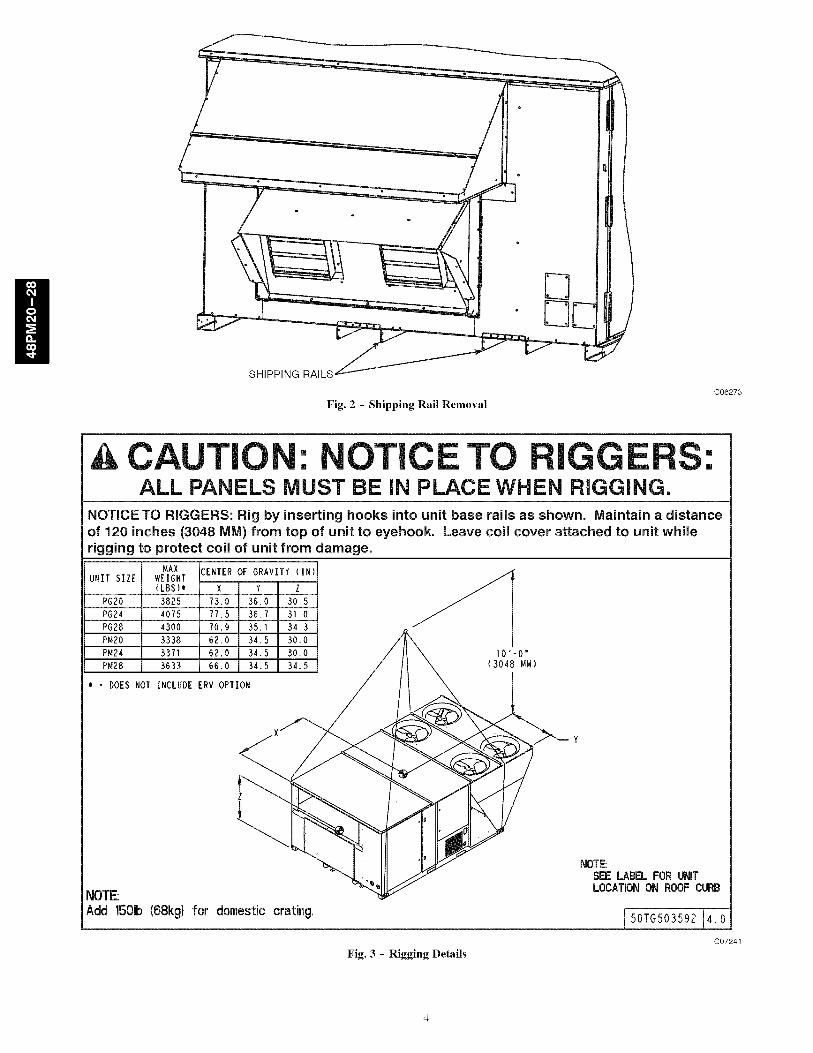
Fig. 2 - Shipping Rail Removal
C06273
CAUTION: NOTICE TO RIGGERS:ALL PANELS MUST BE IN PLACE WHEN RIGGING.
NOTICETO RIGGERS: Rig by inserting hooks into unit base rails as shown. Maintain a distanceof 120 inches (3048 MM) from top of unit to eyehook. Leave coil cover attached to unit whilerigging to protect coil of unit from damage.
MAXUNIT SIZE WEIGHT
(LBS}_
PG20 3825
PG24 4075
PG28 4300
PM20 3338
PM24 3371
P_28 3633
- DOES NOT INCLUDE
NOTE:Add 1501b(68kg)
CENTER OF GRAVITY (IN) /'ix Y Z
73.0 36.0 30.5
77.5 36.7 31.0
70.9 35.1 34.3
62.0 34.5 30.0 /'_
_o°_,_,o_o //\ ,_oOiO;.,
for domestic crating.
Fig. 3 - Rigging Details
NOTE:SEE LABELFOR UNITLOCATIONON ROOFCURB
50TG503592 4.0
C07241

'Ji
NO]ES:oRE OUTDOOR USE ONLY
2 WEIGHTS SHOWN ARE FOR 48PM (LOW NEAT) UNiT
_'iTH MANUAL 25% OUTDOOR AIR OPTION, ALUMINUM COILS,
ANB STANDARD DRIVE EON WEIGN{S OF OPTIONAL
EOUiPMENT CONSULT PRODUCT DATA BOON
S DO NOT LOCATE ADJACENT UNITS W_T_ RLUE
DISCHARGE FACING ECONOMIZER INLET_IN CLEARANCES TO BE
NIGHT SIDE 60 I' (18291 CONDENSER AIR
LEFT SIDE ID S" iSO481 OUTSIDE AIRFRONT SIDE 5 S' [9/51 SERVICE
D' O' [1829] CONDENSER COIL80" [2438] COIL REMOVAL
REAR SIDE G O" [18RD] CONDENSER AIRS D' [1981] ECONOMIZER REMOVAL
TOP 8 O [18Rg] CONDENSER FANBOTTOM 1 21' [356] COMBUSTIBLE BUREACE (_/0 CURS}
FLUE OUTLEI 40" {1219] COMBUSTIBLE SURFACES
/UIIL]TT METERS/REGULATORS/RELIEPSFOR SMALLER SERVICE AND OPERATIONAL CLEARANCES,
CONTACT CARRIER ARRLIEATION ENGINEERING DEPARTMENT
5 DOWN SNOI I)UCTS DESIGNED TO BE ATTACNED TO ACCESSORYROOF CURB ONLY IF UNIT iS _OUNYED SiDE SUPPLY, _m
iS RECOMMENDED THE DUCTS MUST SE SUPPORTED BY
CROSS BRACES AS DONE ON ACCESSORY ROOF CURB
6 Db_ENSIONS [N[ ] ARE IN _]LLIMETERS OR KILOGRAMS
7 WITH THE EXCEPTION OF CLEARANCE FOR THE CONDENSER COH
AND THE DAMPER/POWER EXHAUST AS STATED IN NOTE #3, AREMOVABLE FENCE OR BARRICADE REQUIRES NO CLEARANCE
8 DIMENSIONS ARE FROM OUTSIDE OF BASE RAIL
ALLOW S 5XID [S} ON EAC_ SIDE FOR TOP COVER DR!P EDGE
DIRECTION OF AIRFLOW
CENIEN OR BRAVIIT
1[ OUTSIDE AIR
[ INTAKE HOOD
42 5/8
ilOS2]SAROMETREC
RELIEF ROOD/POWER EXHAUST
so [oIOUTSIDE
14 S//6i5601I
LEFTSIDE
tBB I12
[572}
POWER EXBAUS] b
J11BY GEl BONV
ODTLE1 (OPIION) /
NORFUSED DISCONNECT_ANDLE (OP]iON/F]ELD
INSTALLED)
OPERATING UNIT i CENTER OFi UNii WEIGHt, HEIGHT i OCATIO CORNER WEIGHT
i SiZE BASE ...... } #RAVIiTY _ _ LS .....EBB [NB] IN {MM)i_N [MM]iIN [M_} IN i'NM] A ........ C _ D
PMZO R3B9 I/OBB] 58-1/8i 6R i 34 _/2 BSS11476) {297]
PMB4 8344 [1DNB] 58 118 6"__1476111157B;i [B/S} iB99]
{RMBBJ.......... 17i;:: _ _''B B,,XBB_O8 S {BS5]
÷ DUCT SZE [1208}
VIEW A-A
/--DAMPEN MOIOR
/ ACCESS PANEL
,. ------]
W
{I I3"
I 50TG505861 Rev. 2.0
C07328
Fig. 4 - Base Unit Dimensions

Roof Mount
Check building codes for weight distribution requirements. Unitoperating weight is shown in Table 1.
Installation Onto Curb
The 48PM units are designed to fit on either the accessory full
perimeter curb. Correct placement of the unit onto the curb is
critical to operating performance. To aid in correct positioning,
3/8-in. diameter locating holes have been added to the unit base
rails. When placing the unit, these holes should line up with the
roof curb edge as shown in Fig. 5 and 6, to assure proper duct
opening alignment. For placement on the roof curb, use the
alignment holes located approximately 2-in. from the end of thebase rail on the return end of the unit. See labels on the side of the
unit for more details.
[]NIT DAMAGE HAZARD
Failure to follow this caution may result in equipmentdamage,
Do not slide unit to position when it is sitting on the curb.Curb gasketing material may be damaged and leaks mayresult,
ALIGNMENTHOLE
(IN BASE
EDGEFLANGE _
ALIGNMENTHOLE SHOULDLINE UP WITHROOF CURB
EDGE FLANGE
C06276
Fig. 5 - Alignment Hole Details
RETURN SUPP_
OPENING OPENING
F--qCURB CURB[---T
RETURN SUPPLY LOPENING OPENING_
ROOFCURB
ALIGNMENTHOLES FORCURB-BOTH
SIDES
C06277
Fig. 6 - Alignment Hole Location
Step 4 -- Field Fabricate Ductwork
On vertical units, secure all ducts to roof curb and buildingstructure. Do not connect ductwork to unit. For horizontal
applications, field-supplied flanges should be attached to
horizontal discharge openings and all ductwork secured to the
flanges. Insulate and weatherproof all external ductwork, joints,
and roof openings with counter flashing and mastic in accordance
with applicable codes.
Ducts passing through an unconditioned space must be
insulated and covered with a vapor barrier.
If a plenum return is used on a vertical unit, the return should be
ducted through the roof deck to comply with applicable fire codes.
A minimum clearance is not required around ductwork. Cabinet
return-air static shall not exceed -0.35-in. wg with econonfizer or
0.45-in. wg without econonfizer.
These units are designed for a minimum continuous return-air
temperature in heating of 50°F (dry bulb), or an internfittent
operation down to 45°F (dry bulb), such as when used with a nightset-back thermostat.
To operate at lower return-air temperatures, a field-supplied
outdoor-air temperature control must be used to initiate both stages
of heat when the temperature is below 45°F. Indoor comfort may
be compronfised when these lower air temperatures are used with
insufficient heating temperature rise.

TableI - Physical Data
UNIT 48PM 20 24 28
NOMINAL CAPACITY (TONS) 18 20 25VOLTAGE (volts) 208/230 / 460 / 575 208/230 / 460 / 575 208/230 / 460 / 575OPERATING WEIGHT (Ibs)
2329 2344 2494Economizer 170 170 195
Roof Curb 14-in ... 24-in 305 ... 385 305 ... 385 270 ... 345REFRIGERANT SYSTEM
Refrigerant ... Metering Device Puron (410a) ... Balanced- Port TXV with Bypass
# Circuits ... # Comp, 2 ... 2 2 ... 2 2 ... 2
STD Unit Charge A ... B (Ibs) 13,7 ... 12,0 15,0 ... 15,0 16,7 ... 16,7COMPRESSOR Scroll
Oil Type Copeland 3MA
Oil A ... B ... C (oz) 110 ... 60 110 ... 110 110 ... 110HIGH-PRESSURE SWITCH (psig)
Cutout... Reset (Auto,) 630+/-10 ... 505+/-20 630+/-10 ... 505+/-20 630+/-10 ... 505+/-20LOW-PRESSURE SWITCH (psig)
Cutout ... Reset (Auto.) 40 +/- 7 ... 80 +/-7 40 +/- 7 ... 80 +/-7 40 +/- 7 ... 80 +/-7FREEZE PROTECTION THERMOSTAT
Opens ... Closes 30 +/-5 ... 45 +/-5 30 +/-5 ... 45 +/-5 30 +/-5 ... 45 +/-5CONDENSER COIL Microchannel
Circuit A... B Outer...Inner Outer...Inner Outer...Inner
Rows...Fins/in. 1 ... 20 1 ... 20 1 ... 20
Face Area (sq ft) 52.6 57 65.5CONDENSER FAN (type) Propeller
Quantity...Diameter (in,) 4 ... 22 6 ... 22 6 ... 22Nominal CFM (Total, all fans) 14400 21000 21000Motor Hp _, Watts 0,25 ... t400 0,25 ... 2100 0,25 ... 2100
Nominal RPM 1100 1100 1100EVAPORATOR COIL Round Tube Plate Fin
Circuit A... B Bottom...Top Bottom...Top Bottom...Top
Rows... Fins/in. 4..15 4..15 4..15
Face Area (sq ft) 23.1 23.1 28.9Condensate drain corm, Size (in,) 3/4 NPT 3/4 NPT 3/4 NPTEVAPORATOR FAN (see motor & drive tables for more)
Fan Quantity ... Size (in,)Type DriveNominal CFMFan Bearing TypeMaximum Fan RPM
Blower Shaft Diameter (in,)Blower Pulley TypeFILERS
RA Filter # ... size (in)
Economizer OA inlet screen # ... size (in)GAS HEAT SECTION
Manifold Pressure (in. wg.)Natural Gas Vertical ... Horizontal
Liquid Propane Vertical ... HorizontalThermostat Heat Anticipator Setting (amps)
First Stage... Second StageField Gas Connection Size (in,)Gas Supply Pressure Range (in, wg.)Gas Supply Pressure Range (PSlG)
LOW HEAT# of burners (total)Rollout switch opens _, closes (deg F)
Temperature Rise Min - Max (deg F)Natural Gas Input (Btuh) Stage 1,,,Stage 2
Burner Orifice Diameter (in, ,,,drill size)**
Liquid Propane Input*** (Btuh) Stage1 ,,,Stage 2
Burner Orifice Diameter (in, ,,,drill size)**
MEDIUM HEAT
# of burners (total)Rollout switch opens _, closes (deg F)
Temperature Rise Min - Max (deg F)Natural Gas Input (Btuh) Stage 1,,,Stage 2
Burner Orifice Diameter (in, ,,,drill size)**
Liquid Propane Input*** (Btuh) Stage 1,,,Stage 2
Burner Orifice Diameter (in, ,,,drill size)**HIGH HEAT
# of burners (total)Rollout switch opens _. closes (deg F)
Temperature Rise Min - Max (deg F)Natural Gas Input (Btuh) Stage 1...Stage 2
Burner Orifice Diameter (in....drill size)**
Liquid Propane Input*** (Btuh) Stage 1...Stage 2
Burner Orifice Diameter (in....drill size)**
2 ... 15xllBelt7200
1400
1.t875
Fixed
2 ... 15xllBelt8000
Ball- Concentric Lock1400
1,t875Fixed
2 ... 15xllBelt
10000
1400
1.t875
Fixed
9 ... 16x25 9 ... 16x25 9 ... 20x25
3 ... 20x25 3 ... 20x25 3 ... 20x25
3.00 ... 2,95
3.00 ... 2,8
0.98 ... 0,44
3/4
5,5 -- 13,0
0.235 -- 0.469
5
225 ...t75
15 -- 45
199,000...250,000
0,136...29
207,000...250,000
0.110...35
3.00 ... 2,95
3.00 ... 2,8
0.98 ... 0,44
3/4
5,5 -- 13,0
0.235 -- 0.469
5
225 ...t75
15 -- 45
199,000...250,000
0,136...29
207,000...250,000
0.110...35
8
225 ...17525 - 55
281,000...365,000
0.1285...30
291,000...365,000
0.1015...38
8
225 ...17525 - 55
317,000...400,000
0.136...29
331,000...400,000
0.110...35
8
225 ...17525 - 55
281,000...365,000
0.1285...30
291,000...365,000
0.1015...38
8
225 ...17525 - 55
317,000...400,000
0.136...29
331,000...400,000
0.110...35
3.00 ... 2,95
3.00 ... 2,8
0,98 ... 0,44
3/45,5 - 13,0
0,235 - 0,469
5
225 ...t75
15 - 45
199,000...250,000
0,136...29
207,000...250,000
0.110...35
8
225 ...17525 - 55
281,000...365,000
0.1285...30
291,000...365,000
0.1015...38
8
225 ...17525 - 55
317,000...400,000
0.136...29
331,000...400,000
0.110...35
Aluminum Evaporator coil/Aluminum Condenser coil with low heat
** For applications less than 2000 ft elevation.
*** Vertical application numbers shown. For horizontal, see product data book.

Table 2 - Fan Motor and Drive Data -- Vertical Supply/Return
UNIT 48PM 20 24 28
Voltage (volts) 208/230 and 460 575 208/230 and 460 575 208/230 and 460 575LOW RANGE
Motor HP 3,7 5 3,7 5 5 5
Motor Nominal RPM 1750 1750 1750 1750 1750 1750
Maximum Continuous BHP 4.26 5.75 4.26 5.75 5.37 / 5.75 5.75Maximum Continuous Watts 3700 5015 3700 5015 4578 / 5115 5015Motor Frame Size 56HZ S184T 56HZ S184T S184T S184T
Motor shaft diameter (in.) 7/8 1 1/8 7/8 1 1/8 1 1/8 1 1/8Motor Pulley Pitch Diameter Min - Max (in) 2.7 - 3,7 3,7 - 4,7 2.7 - 3,7 3,7 - 4,7 3,7 - 4,7 3,7 - 4,7Fan RPM Range 685-939 751-954 685-939 751-954 687-873 687-873
Blower Pulley Pitch Diameter (in.) 6,8 8,6 6,8 8,6 9,4 9,4Pulley center line distance (in.) 11.293-13,544 9,81 - 13.055 11.293-13,544 9,81 - 13.055 9,81 - 13.055 9,81 - 13.055
Belt, Quantity_Type_Length (in.) 1 _BX38_39.8 1_BX40_41.8 1 _BX38_39.8 1 _BX40_41.8 1_BX41 _42.8 1_BX41 _42.8Speed change per turn - moveable pulley (RPM) 42 34 42 34 31 31
Moveable pulley maximum full turns 6 6 6 6 6 6Factory Speed setting (RPM) 812 853 812 853 780 780
MID-LOW RANGEMotor HP 5 5 5 5 5 5Motor Nominal RPM 1750 1750 1750 1750 1750 1750
Maximum Continuous BHP 5,37 / 5,75 5,75 5,37 / 5,75 5,75 5,37 / 5,75 5,75
Maximum Continuous Watts 4578 / 5115 5015 4578 / 5115 5015 4578 / 5115 5015Motor Frame Size S184T S184T S184T S184T S184T S184T
Motor shaft diameter (in.) 1 1/8 1 1/8 1 1/8 1 1/8 1 1/8 1 1/8
Motor Pulley Pitch Diameter Min - Max (in) 3,7 - 4,7 3,7 - 4,7 3,7 - 4,7 3,7 - 4,7 4,8 - 6 4,8 - 6Fan RPM Range 949-1206 949-1206 949-1206 949-1206 805-1007 805-1007Blower Pulley Pitch Diameter (in.) 6,8 6,8 6,8 6,8 10,4 10,4
Pulley center line distance (in,) 9,81 - 13,055 9,81 - 13,055 9,81 - 13,055 9,81 - 13,055 9,81 - 13,055 9,81 - 13,055Belt, Quantity_Type_Length (in.) 1 _BX38_39.8 1_BX38_39.8 1 _BX38_39.8 1 _BX38_39.8 1_BX45_46.8 1_BX45_46.8
Speed change per turn - moveable pulley (RPM) 43 43 43 43 34 34Moveable pulley maximum full turns 6 6 6 6 6 6
Factory Speed setting (RPM) 1078 1078 1078 1078 906 906MID-HIGH RANGE
Motor HP 7,5 7,5 7,5 7,5 7,5 7,5Motor Nominal RPM 1750 1750 1750 1750 1750 1750
Maximum Continuous BHP 7,66/8,51 / 8,63 8,63 7,66/8,51 / 8,63 8,63 7,66/8,51 / 8,63 8,63Maximum Continuous Watts 6458 / 7586 7586 6458 / 7586 7586 6458 / 7586 7586Motor Frame Size S213T S213T S213T S213T S213T S213T
Motor shaft diameter (in.) 1 3/8 1 3/8 1 3/8 1 3/8 1 3/8 1 3/8Motor Pulley Pitch Diameter Min - Max (in) 4,8 - 6.0 4,8 - 6.0 4,8 - 6.0 4,8 - 6.0 4,8 - 6.0 4,8 - 6.0
Fan RPM Range 941-1176 941-1176 941-1176 941-1176 941-1176 941-1176Blower Pulley Pitch Diameter (in.) 8,9 8,9 8,9 8,9 8,9 8,9
Pulley center line distance (in.) 9,025-12.179 9,025-12.179 9,025-12.179 9,025-12.179 9,025-12.179 9,025-12.179Belt, Quantity_Type_Length (in.) 1 _BX42_43.8 1_BX42_43.8 1 _BX42_43.8 1 _BX42_43.8 1_BX42_43.8 1_BX42_43.8Speed change per turn - moveable pulley (RPM) 39 39 39 39 39 39
Moveable pulley maximum full turns 6 6 6 6 6 6Factory Speed setting (RPM) 1059 1059 1059 1059 1059 1059
HIGH RANGEMotor HP 10 10 10 10 10 10
Motor Nominal BPM 1750 1750 1750 1750 1750 1750
Maximum Continuous BHP 9.94/10.45 / 11.19 11.5 9.94/10.45 / 11.19 11.5 9.94/10.45 / 11.19 11.5Maximum Continuous Watts 8284 / 9330 9711 8284 / 9330 9711 8284 / 9330 9711Motor Frame Size S215T S215T S215T S215T S215T S215T
Motor shaft diameter (in.) 1 3/8 1 3/8 1 3/8 1 3/8 1 3/8 1 3/8
Motor Pulley Pitch Diameter Min - Max (in) 4,3 - 5,5 4,3 - 5,5 4,3 - 5,5 4,3 - 5,5 4,3 - 5,5 4,3 - 5,5Fan RPM Range 1014-1297 1014-1297 1014-1297 1014-1297 1014-1297 1014-1297
Blower Pulley Pitch Diameter (in.) 7,4 7,4 7,4 7,4 7,4 7,4Pulley center line distance (in,) 9,025-12.179 9,025-12.179 9,025-12.179 9,025-12.179 9,025-12.179 9,025-12.179
Belt, Quantity_Type_Length (in.) 2_BX38_39.8 2_BX38_39.8 2_BX38_39.8 2_BX38_39.8 2_BX38_39.8 2_BX38_39.8Speed change per turn - moveable pulley (RPM) 47 47 47 47 47 47Moveable pulley maximum full turns 6 6 6 6 6 6
Factory Speed setting (RPM) 1156 1156 1156 1156 1156 1156

Table 3 - Fan Motor and Drive Data -- Horizontal Supply/Return
UNIT 48PM 20 24 28
Voltage (volts) 208/230 and 460 575 208/230 and 460 575 208/230 and 460 575LOW RANGE
Motor HP N/A N/A N/A N/A 5 5Motor Nominal RPM N/A N/A N/A N/A 1750 1750
Maximum Continuous BHP N/A N/A N/A N/A 5,37 / 5,75 5,75Maximum Continuous Watts N/A N/A N/A N/A 4578 / 5115 5015
Motor Frame Size N/A N/A N/A N/A S184T S184T
Motor shaft diameter (in.) N/A N/A N/A N/A 1 1/8 1 1/8Motor Pulley Pitch Diameter Min - Max (in) N/A N/A N/A N/A 3,7 - 4,7 3,7 - 4,7Fan RPM Range N/A N/A N/A N/A 687-873 687-873
Blower Pulley Pitch Diameter (in.) N/A N/A N/A N/A 9,4 9,4Pulley center line distance (in,) N/A N/A N/A N/A 9,81 - 13,055 9,81 - 13,055
Belt, Quantity_Type_Length (in.) N/A N/A N/A N/A 1 ..BX41 ..42.8 1..BX41 ..42.8Speed change per turn - moveable pulley (RPM) N/A N/A N/A N/A 31 31
Moveable pulley maximum full turns N/A N/A N/A N/A 6 6Factory Speed setting (RPM) N/A N/A N/A N/A 780 780
MID-LOW RANGEMotor HP 3,7 5 3,7 5 5 5Motor Nominal RPM 1750 1750 1750 1750 1750 1750
Maximum Continuous BHP 4,26 5,75 4,26 5,75 5,37 / 5,75 5,75
Maximum Continuous Watts 3700 5015 3700 5015 4578 / 5115 5015Motor Frame Size 56HZ S184T 56HZ S184T S184T S184T
Motor shaft diameter (in.) 7/8 1 1/8 7/8 1 1/8 1 1/8 1 1/8
Motor Pulley Pitch Diameter Min - Max (in) 2.7 - 3,7 3,7 - 4,7 2.7 - 3,7 3,7 - 4,7 4,8 - 6.0 4,8 - 6.0Fan RPM Range 896-1227 873-1108 896-1227 873-1108 805-1007 805-1007Blower Pulley Pitch Diameter (in.) 5,2 7,4 5,2 7,4 10,4 10,4
Pulley center line distance (in.) 11.293-13,544 9,81 - 13.055 11.293-13,544 9,81 - 13.055 9,81 - 13.055 9,81 - 13.055Belt, Quantity_Type_Length (in.) 1..BX35..36.8 1..BX38..39.8 1 ..BX35..36.8 1..BX38..39.8 1 ..BX45..46.8 1..BX45..46.8
Speed change per turn - moveable pulley (RPM) 55 39 55 39 34 34Moveable pulley maximum full turns 6 6 6 6 6 6
Factory Speed setting (RPM) 1062 991 1062 991 906 906MID-HIGH RANGE
Motor HP 5 5 5 5 7.5 7.5Motor Nominal BPM 1750 1750 1750 1750 1750 1750
Maximum Continuous BHP 5.37 / 5.75 5.75 5.37 / 5.75 5.75 7.66/8.51 / 8.63 8.63Maximum Continuous Watts 4578 / 5115 5015 4578 / 5115 5015 6458 / 7586 7586Motor Frame Size S184T S184T S184T S184T S213T S213T
Motor shaft diameter (in.) 1 1/8 1 1/8 1 1/8 1 1/8 1 3/8 1 3/8Motor Pulley Pitch Diameter Min - Max (in) 3,7 - 4,7 3,7 - 4,7 3,7 - 4,7 3,7 - 4,7 4,8 - 6.0 4,8 - 6.0
Fan RPM Range 1113-1414 1113-1414 1113-1414 1113-1414 941-1176 941-1176Blower Pulley Pitch Diameter (in.) 5,8 5,8 5,8 5,8 8,9 8,9
Pulley center line distance (in.) 9,81 - 13.055 9,81 - 13.055 9,81 - 13.055 9,81 - 13.055 9.025-12.179 9.025-12.179Belt, Quantity_Type_Length (in.) 1..BX35..36.8 1..BX35..36.8 1 ..BX35..36.8 1..BX35..36.8 1 ..BX42..43.8 1..BX42..43.8Speed change per turn - moveable pulley (RPM) 50 50 50 50 39 39
Moveable pulley maximum full turns 6 6 6 6 6 6Factory Speed setting (RPM) 1264 1264 1264 1264 1059 1059
HIGH RANGEMotor HP 7.5 7.5 7.5 7.5 10 10
Motor Nominal BPM 1750 1750 1750 1750 1750 1750
Maximum Continuous BHP 7.66/8.51 / 8.63 8.63 7.66/8.51 / 8.63 8.63 9.94/10.45 / 11.19 11.5Maximum Continuous Watts 6458 / 7586 7586 6458 / 7586 7586 8284 / 9330 9711Motor Frame Size S213T S213T S213T S213T S215T S215T
Motor shaft diameter (in.) 1 3/8 1 3/8 1 3/8 1 3/8 1 3/8 1 3/8
Motor Pulley Pitch Diameter Min - Max (in) 5,4 - 6,6 5,4 - 6,6 5,4 - 6,6 5,4 - 6,6 4,3 - 5,5 4,3 - 5,5Fan RPM Range 1096-1339 1096-1339 1096-1339 1096-1339 1014-1297 1011-1293
Blower Pulley Pitch Diameter (in.) 8,6 8,6 8,6 8,6 7,4 7,4Pulley center line distance (in.) 9.025-12.179 9.025-12.179 9.025-12.179 9.025-12.179 9.025-12.179 9.025-12.179
Belt, Quantity_Type_Length (in.) 1..BX42..43.8 1..BX42..43.8 1 ..BX42..43.8 1..BX42..43.8 1 ..BX38..39.8 1..BX38..39.8Speed change per turn - moveable pulley (RPM) 41 41 41 41 47 47Moveable pulley maximum full turns 6 6 6 6 6 6
Factory Speed setting (RPM) 1218 1218 1218 1218 1156 1156

Step 5 -- Make Unit Duct Connections
Vertical Configuration
Unit is shipped for vertical supply and return duct connections.Ductwork openings are shown in Fig. I and 4. Duct connections
for vertical configuration are shown in Fig. 7. Field-fabricated
concentric ductwork may be connected as shown in Fig. 8. The
unit is designed to attach the ductwork to the roof curb. Do not
attach duct directly to the unit.
UNIT DAMAGE AND PERSONAL INJURY HAZARD
Failure to follow this warning could cause equipment
damage and/or personal injury.
For vertical supply and return units, tools or parts could
drop into ductwork and cause an injury. Install a90-degree turn in the return ductwork between the unit
and the conditioned space. If a 90-degree elbow cannot
be installed, then a grille of sufficient strength anddensity should be installed to prevent objects from
falling into the conditioned space.
Horizontal Applications
Horizontal units are shipped with outer panels that allow for side
by side horizontal duct connections. If specified during ordering,
the unit will be shipped with the vertical duct openings blocked off
from the factory, ready for side supply installation. If the horizontal
supply/return option was not specified at time of ordering the unit,
a field-installed accessory kit is required to convert the vertical unit
into a horizontal supply configuration.
Installation of the duct block-off covers should be completed prior
to placing the unit unless sufficient side clearance is available. A
minimum of 66-in. is required between the unit and any
obstruction to install the duct block-off covers. Side supply duct
dimensions and locations are shown on Fig. 4. Install ductwork to
horizontal duct flange connections on side of unit.
ECONOMIZER
HEATEXCHANGER
NOTE: Do not drill in this area. Damageto basepanmay result in water leak.
C06278
Fig. 7 - Air Distribution - Vertical Supply/Return
ECONOMIZER
SEE _', \\ " ,' SEE
NOTE/' ' \\ , ..... / NOTE
1 i"AIR OUT AIRIN AIR OUT
HEATEXCHANGER
NOTE: Do not drill in this area. Damageto basepanmay result in water leak.
C06279
Fig. 8 - Air Distribution - Concentric Duct
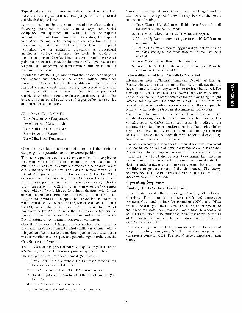
Step 6 -- Install Flue Hood and Inlet Hood
Flue hood (smaller hood), inlet hood (larger hood), and screens areshipped inside the unit in the fan section. To install, remove the
heat panel. The flue hood is attached to the heat section panel from
the outside using the screws provided. (See Fig. 9.)
The inlet hood is installed by inserting the hood through the back
of the heat panel. Attach the hood by inserting the screws provided
through the clearance holes in the heat panel and into the intakehood.
Install the screens into both hoods using the screws and retaining
nuts provided with the unit.
Attach the cover of the observation hole on the intake hood and
then replace the heat panel onto the unit to complete theinstallation.
NOTE: When properly installed, the flue hood will line up with
the combustion fan housing. (See Fig. 10.)
Fig. 9 - Flue and Inlet Hood Locations
C06280
10

HEATEXCHANGERSECTION
COMBUSTION• FAN HOUSING
INDUCED-DRAFTMOTOR
MAIN BURNERSECTION
C06281
Fig. 10 - Combustion Fan Housing Location
Step 7 -- Trap Condensate Drain
See Fig. 11 for drain location. One 3/4-in. half coupling is
provided outside unit evaporator section for condensate drain
connection. A trap at least 4-in. deep must be used. (See Fig. 12.)
All units must have an external trap for condensate drainage. Install
a trap at least 4-in. deep and protect against freeze-up. If drain line
is installed downstream from the external trap, pitch the line away
from the unit at I-in. per 10 ft of run. Do not use a pipe sizesmaller than the unit connection.
Step 8 -- Install Gas Piping
Unit is equipped for use with natural gas. Refer to local building
codes, or in the absence of local codes, to ANSI Z223.l-latest year
and addendum Z223.1A-latest year entitled NFGC. In Canada,installation must be in accordance with the CANI.BI49.1 and
CANI.BI49.2 installation codes for gas burning appliances.
Support gas piping. For example, a 3/4-in. gas pipe must have one
field-fabricated support beam every 8 ft. Therefore, an 18-ft long
gas pipe would have a minimum of 3 support beams.
Install field-supplied manual gas shutoff valve with a 1/8-in. NPT
pressure tap for test gauge connection at unit. The pressure tap is
located on the gas manifold, adjacent to the gas valve. Field gas
piping must include sediment trap and union. (See Fig. 13.)
UNIT DAMAGE AND PERSONAL INJURYHAZARD
Failure to follow this warning could result in damage toequipment and/or personal injury.
Do not pressure test gas supply while connected to unit.
Always disconnect union before servicing.
IMPORTANT: Natural gas pressure at unit gas connection must
not be less than 5.5-in.wg or greater than 13.0-in.wg.
Size gas-supply piping for 0.5-in. wg maximum pressure drop.
Do not use supply pipe smaller than unit gas connection.
-DAMPER MOTORACCESS COVER
3/4"
DRAIN CONNECTION
4,SUPPLY
AIR
5-1/4[132]
47-1/2 --[t2o81
I'RETURN
AIR
Fig. 11 - Condensate Drain Details
C06282
1OoNFETJN_)FP_IRE \ Ep_A,_LE t I I _
OPEN II I/VENT t [ II
tSEE
NOTE
,.ROOFCURB
NOTE: Trapshould be deep enough to offsetmaximum unitstatic differenceA 4-in. trap is recommended.
C06291
Fig. 12 - Condensate Drain Piping Details
MANUALSHUTOFF
(FIELDSUPPLIED) "xh% r"_
GAS
/ (1/8-NPTPLUG)o__J
UNIT
SEDIMENTTRAPuNION
C06236
Fig. 13 - Field Gas Piping
H
11

Step 9 -- Make Electrical Connections
Field Power Supply
Unit is factory wired for voltage shown on unit nameplate. Be sure
to check for correct voltage.
When installing units, provide disconnect per NEC (National
Electrical Code) of adequate size (MOCP [Maxinmm Overcurrent
protection] of unit is on the informative plate). (See Table 4 and 5.)
All field wiring must comply with NEC and local codes. Size wire
based on MCA (Minimum Circuit Amps) on the unit informative
plate. See Fig. 14 for power wiring connection to the unit power
ternfinal block and equipment ground.
Route power and ground lines through control box end panel or
unit basepan (see Fig. 4) to connections as shown on unit wiring
diagram and Fig. 14.
UNIT DAMAGE HAZARD
Failure to follow this caution may result in damage to unit.
The correct power phasing is critical to the operation of the
scroll compressors. An incorrect phasing will result in
compressor shutdown on thermal overload and possible
damage to compressor. Should this occur, power phase
correction must be made to the inconfing power.
ELECTRICAL SHOCK AND FIRE HAZARD
Failure to follow this warning could result in electrical
shock, fire, or death.
Unit cabinet must have an uninterrupted or unbroken
electrical ground to nfininfize the possibility of personal
iniury if an electrical fault should occur. This ground
may consist of electrical wire connected to unit ground
lug in control compartment or conduit approved for
electrical ground when installed in accordance withNEC ANSI/NFPA latest edition, and local electrical
codes. Do not use gas piping as an electrical ground.
Field wiring nmst conform to temperature linfitations for type "T"
wire. All field wiring must comply with NEC and local
requirements.
Operating voltage to compressor must be within voltage range
indicated on unit nameplate. On 3-phase units, voltages between
phases must be balanced within 2%.
Unit failure as a result of operation on improper line voltage or
excessive phase imbalance constitutes abuse and may cause
damage to electrical components.
Field Control Wiring
Unit can be controlled with either a Carrier-approved accessory
thermostat. Install thermostat according to the installation
instructions included with accessory. Locate thermostat assemblyon a solid interior wall in the conditioned space to sense average
temperature.
Route thermostat cable or equivalent single leads of colored wire
from subbase ternfinals through conduit into unit to low-voltage
connections as shown on unit label wiring diagram and in Fig. 15.
NOTE: For wire runs up to 50 fl, use no. 18 AWG (American
Wire Gauge) insulated wire (35°C nfininmm). For 50 to 75 ft, use
no. 16 AWG insulated wire (35°C nfininmm). For over 75 ft, use
no. 14 AWG insulated wire (35°C Mininmm). All wire larger than
no. 18 AWG cannot be directly connected at the thermostat and
will require a junction box and splice at the thermostat.
c'_w¢o
O_:
g_
.... 1
II FIELDrIL_ m POWERI
SUPPLY
IItII1'ii
__ ]
TBI
[ ]EQUIP GND
LEGENDEQUIP - EquipmentGND - GroundNEC - National Electrical CodeTB - Terminal Board
NOTE: The maximum wire size for TB1 is 2/0
Fig. 14 - Field Power Wiring Connections
C06293
THERMOSTAT ASSEMBLY
---4-
ROOFTOPUNIT
C06298
Fig. 15 - Field Control Thermostat Wiring
Set heat anticipator settings as follows:
VOLTAGE
All
STAGE 1 STAGE 1 AND 2(Wl) ON (Wl AND W2) ON
0.98 0.44
Settings may be changed slightly to provide a greater degree of
comfort for a particular installation.
Step 10 -- Install Outdoor Air Hood
Perform the following procedure to install the outdoor-air hood on
units equipped with an econonfizer, two-position damper, or
manual outdoor air damper:
1. Remove blank panel from return end of unit (hood section).
Save the screws. See Fig. 16 for shipping location of
components.
2. Hood sides are fastened to sides of outdoor air opening.
Remove the hood sides and save the screws (3 each side).
3. Remove the bracket holding the bottom half of the hood in
the shipping position. Remove the hood bottom half and
filters (or manual dampers on units so equipped) fromoutdoor section.
12

NOTE: On units without economizers, the components areattached to the unit basepan. To access the components, remove thepanel below the outdoor air intake section.
4. Remove inner filter track from shipping position in outdoorsection. Position inner filter track so the track is facingoutward from the unit. Install the filter track with 4 screws
provided.
5. Apply seal strip (provided) to back flange of both hoodsides where hood side connects to the unit back panel. (SeeFig. 170
6. Apply seal strip (provided) to top flange of both hood sideswhere hood sides connect to the hood top panels. (See Fig.17.)
7. Install hood sides to the back panels using the screws fromStep 2. The sloped flanges point outward. The drip edges ofthe side panels should face outward as well. The filterguides to the hood sides. The flanges of the filter guidesshould face inward to hold the filters in place. (See Fig. 17.)
8. Apply seal strip along the entire length of the bottom flangeof the hood top. (See Fig. 17.)
9. Install the bottom part of the hood top using 4 screwsprovided. (See Fig. 17.)
10. Remove the packaging from filters (3) and install into thefilter tracks. Slide the filters to the sides then place the lastfilter into the center of the filter track.
NOTE: For units with manual dampers, replace the end filterswith the manual dampers. Install the filter in the center between themanual dampers.
11. Install the filter retainer track along the bottom edge of theoutdoor air hood using 4 screws provided. (See Fig. 17.)
12. Install top section of the outdoor air hood using 9 screws
provided. (See Fig. 17.) See Fig. 18 for a picture of theassembled outdoor air hood.
NOTE: For filter removal, remove the four screws holding thefilter retainer. The filters can then be removed, cleaned, or replaced.Install the filters by reversing the procedure.
Manual Damper Assembly
For units equipped with manual dampers, the assembly process issimilar to the outdoor air hood for units with economizers. There
are two slide dampers shipped with the unit to allow for manualsetting of the outside air volume. When assembling the hood, placeone of the manual slide dampers in each of the end positions andthe remaining filter in the center position. The manual dampers canthen be moved to the appropriate position and then locked intoplace using the screws mounted in the adjustment slots. (See Fig.19.)
HOOD HOOD TOP
HOOD TOP SIDE (BOTTOM HALF)
HOODSIDE
RETURN AIRSECTION
C06283
Fig. 16 - Outdoor-Air Hood Component Shipping Location
13
48PM SIZE
2O
24
28
NOMINALVOLTAGE
(3 Ph, 60Hz)
208/230
46O
575
208/230
46O
575
208/230
46O
575
VOLTAGERANGE
Min Max
187 253
414 506
518 633
187 253
414 506
518 633
187 253
414 506
518 633
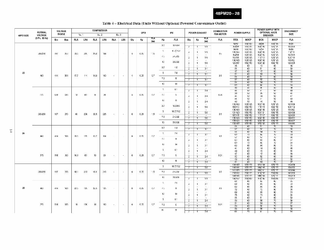
Table 4 - Electrical Data (Units Without Optional Powered Convenience Outlet)
No. 1
RLA LRA
COMPRESSOR
No. 2
RLA LRA
33,5 225 29.6 164
17.7 114 14.8 100
13 80 11 78
40 239 33,5 225
19,5 125 17.7 114
16.6 80 13 80
48.1 245 48.1 245
22.5 125 22.5 125
18 100 18 100
No. 3
RLA LRA
OFM
FLA
Oty Hp (ea)
4 0.25 1,5
4 0.25 0.7
4 0.25 0.7
6 0.25 1,5
6 0.25 0.7
6 0.25 0.7
6 0.25 1,5
6 0.25 0.7
6 0.25 0.7
COMBUSTIONIFM POWER EXHAUST POWER SUPPLY
FAN MOTOR
FLAHp FLA Qty Hp (ea) FLA MCA MOCP
88/87 100/1003.7 10.6/9.6 2 1 5.9 100/99 125/125
94/93 125/1005 16.7/15.2 2 1 5.9 106/104 125/125
0.5 102/99 125/1257.5 24.2/22 2 1 5.9 113/111 125/125
108/105 125/12510 30.8/28 2 1 5.9 120/117 150/150
45 603.7 4.8 2 1 3,1 51 60
47 605 7.6 2 1 3,1 54 60
0.3 51 607.5 11 2 1 3,1 57 60
54 6010 14 2 1 3,1 60 60
36 455 6.1 2 1 2.4 41 50
39 507.5 9 2 1 2.4 0.24 44 50
41 5010 11 2 1 2.4 46 50
103/102 125/1253.7 10.6/9.6 2 1 5.9 115/114 150/150
109/108 125/1255 16.7/15.2 2 1 5.9 121/120 150/150
0.5 117/115 150/1507.5 24.2/22 2 1 5.9 129/126 150/150
123/121 150/15010 30.8/28 2 1 5.9 135/132 175/150
51 603.7 4.8 2 1 3,1 57 60
54 605 7.6 2 1 3,1 60 70
0.3 57 607.5 11 2 1 3,1 63 80
60 7010 14 2 1 3,1 66 80
44 6O5 6.1 2 1 2.4 49 60
47 607.5 9 2 1 2.4 0.24 52 60
49 6010 11 2 1 2.4 54 60
134/132 175/1755 16.7/15.2 2 1 5.9 146/144 175/175
141/139 175/1757.5 24.2/22 2 1 5.9 0.5 153/151 200/175
148/145 175/17510 30.8/28 2 1 5.9 160/157 200/200
62 805 7.6 2 1 3,1 69 90
66 807.5 11 2 1 3,1 0.3 72 90
69 9010 14 2 1 3,1 75 90
51 605 6.1 2 1 2.4 56 60
7.5 9 2 1 2.4 0.24 5954 6060
10 11 56 602 1 2.4 61 70
POWERSUPPLY WITHDISCONNECT
OPTIONAL HACRSIZE
BREAKER
MCA MOCP FLA
8_88 10_100 92/9110_100 12_125 10_10494/94 12_125 9_97
10_106 12_125 112/111102/102 12_125 107/105113/113 12_125 121/11810_108 12_125 11_11212_120 150/150 12_125
45 60 4651 60 5347 60 4954 70 5651 60 5357 70 6054 70 5760 70 6436 40 3841 50 4339 50 4144 50 4741 50 4346 50 49
103/103 12_125 107/10611_115 150/150 121/11910_109 12_125 114/112121/121 150/150 12_126117/117 150/150 123/120129/129 150/150 136/134123/123 150/150 130/12713_135 17_175 144/141
51 70 5357 70 6054 70 5660 70 6357 70 6063 80 6760 70 6466 80 7144 60 4649 60 5147 60 4952 60 5549 60 5254 70 57
134/134 17_175 14_13814_146 17_175 15_152141/141 17_175 14_146153/153 20_200 162/16014_148 17_175 156/15316_160 20_200 170/167
62 80 6569 90 7266 80 6972 90 7669 90 7375 90 8051 60 5356 70 5954 70 5759 70 6256 70 5961 70 64

48PM SIZE
20
24
28
NOMINALVOLTAGE
(3 Ph, 60Hz)
VOLTAGERANGE
Min Max
No. 1
RLA LRA
Table 5 - Electrical Data (Units With Optional Powered Convenience Outlet)
COMPRESSOROFM
No. 2 No. 3
RLA LRA RLA LRA Qty Hp
206/230 187 253 33,5 225 29.6 164
460 414 506 17.7 114 14.6 100
575 518 633 13 80 11 78
206/230 187 253 40 239 33,5 225
460 414 506 19.5 125 17.7 114
575 518 633 16.6 80 13 80
206/230 187 253 46.1 245 46.1 245
460 414 506 22,5 125 22,5 125
575 518 633 18 100 18 100
4 0.25
4 0.25
4 0.25
6 0.25
6 0.25
6 0.25
6 0.25
6 0.25
6 0.25
IFM POWER EXHAUST COMBUSTIONFAN MOTOR
FLA FLA(ea) Hp FLA Qty Hp (ea) FLA
3,7 10,6/9.6 2 1 5.9
5 16,7/15.2 2 1 5.91,5 0.5
7.5 24.2/22 2 1 5.9
10 30,6/28 2 1 5.9
3,7 4,6 2 1 3,1
5 7.6 2 1 3,10.7 0.3
7.5 11 2 1 3,1
10 14 2 1 3,1
5 6,1 2 1 2.4
0.7 7.5 9 2 1 2.4 0.24
10 11 2 1 2.4
3,7 10.6/9.6 2 1 5.9
5 16,7/15.2 2 1 5.91,5 0.5
7.5 24.2/22 2 1 5.9
10 30,6/28 2 1 5.9
3,7 4,6 2 1 3,1
5 7.6 2 1 3,10.7 0.3
7.5 11 2 1 3,1
10 14 2 1 3,1
5 6,1 2 1 2.4
0.7 7.5 9 2 1 2.4 0.24
10 11 2 1 2.4
5 16,7/15.2 2 1 5.9
1,5 7.5 24.2/22 2 1 5.9 0.5
10 30,6/28 2 1 5.9
5 7.6 2 1 3,1
0.7 7.5 11 2 1 3,1 0.3
10 14 2 1 3,1
5 6,1 2 1 2.4
0.7 7.5 9 2 1 2.4 0.24
10 112 1 2.4
POWER SUPPLY WlTHPOWER SUPPLY OPTIONAL HACR
BREAKER
MCA MOCP MCA MOCP
93/92 10_100 93/93 12_12510_104 12_125 10_105 12_125
9_98 12_125 9_99 12_125111/109 12_125 111/111 12_125107/104 12_125 107/107 12_125118/116 150/125 118/118 150/150113/110 12_125 113/113 12_12512_122 150/150 12_125 150/150
46 60 46 6054 60 54 7050 60 50 6057 60 57 7054 60 54 7060 60 60 7057 60 57 7063 80 63 8039 50 39 5044 50 44 5042 50 42 5047 50 47 5044 50 44 5049 60 49 60
10_107 12_125 10_106 12_12512_119 150/150 12_120 150/150114/113 150/150 114/114 150/15012_125 150/150 12_126 150/150122/120 150/150 122/122 150/150134/131 150/150 134/134 150/15012_126 150/150 12_128 150/15014_137 17_175 14_140 17_175
54 60 54 7060 70 60 7057 60 57 7063 80 63 8060 70 60 7066 80 66 8063 80 63 8069 80 69 8047 60 47 6052 60 52 6050 60 50 6055 60 55 7052 60 52 6057 60 57 70
13_137 17_175 13_139 17_175151/149 17_175 151/151 17_17514_144 17_175 14_146 17_17515_156 20_200 15_156 20_200153/150 20_175 153/153 20_20016_162 20_200 16_165 20_200
65 80 65 8072 90 72 9069 90 69 9075 90 75 9072 90 72 9076 100 76 10054 60 54 7059 60 59 7057 60 57 7062 70 62 7059 60 59 7064 80 64 80
DISCONNECTSIZE
FLA
97/96111/110104/103118/116113/111127/124121/117134/131
5O57536O57646O674147455O4752
113/112126/125120/118133/132128/126142/139136/133150/146
57646O676471677449555358556O
146/144160/156155/152168/166162/159176/173
6976738O768357626O666268

LEGENDFLA- FullLoadAmpsHACR- Heating,AirConditioningandRefrigerationIFM- Indoor(Evaporator)FanMotorLRA- LockedRotorAmpsMCA- MinimumCircuitAmpsMOCP- MaximumOvercurrentProtectionNEC- NationalElectricalCodeOFM- Outdoor(Condenser)FanMotorRLA- RatedLoadAmps
*Fuse or HACR circuit breaker
NOTES:
1. In compliance with NEC requirements for muttimotor and combination load equipment (refer to NEC Articles 430 and 440), the overcurrent
protective device for the unit shall be fuse or HACR breaker. Canadian units may be fuse or circuit breaker.
2. Unbalanced 3-Phase Supply Voltage
Never operate a motor where a phase imbalance in supply voltage is greater than 2%. Use the following formula to determine the percent-
age of voltage imbaIance.
% Voltage Imbalance = 1 O0 xmax voltage deviation from average voltage
average voltage
Example: Supply voltage is 460-3-60
AB = 452 v
BC = 464 v
AC = 455 v
Average Voltage = 452 + 464 + 4553
= 13713
= 457
Determine maximum deviation from average voltage.
(AB) 457 452 = 5 v
(BC) 464 - 457 = 7 v
(AC) 457 455 = 2 v
Maximum deviation is 7 v.
Determine percent of voltage imbalance.
7% Voltage Imbalance = 1 O0 x
457
= 1.53%
This amount of phase imbalance is satisfactory as it is below the maximum allowable 2%.
II_II'OI,tq:&NT: II the supply voltage phase irnbaiance is rnorc than 2%, contact your local electric utility company irnrnediatety.
3. The convenience outlet fuIt load amps (FLA) are 5, 3, and 3 for 208/230,460, 575-V units, respectiveiy.

SEAL
STRIP
TOP HOODSECTION
//
HOOD
SECTION
FILTERRETAINER
<
MANUALDAMPER
(IF EQUIPPED)
ADD
SEAL
HOOD STRIP ADDSEAL
INNER
FILTER
TRACKADDSEALSTRIP
HOODSIDE
UNIT
BACK
PANEL
ADDSEAL
j•
NOTE: Units with manual damper only use one filter.
Fig. 17 - Outdoor-Air Hood Details
C07199
Fig. 18 - Outdoor-Air Hood Assembled
C06285
Step 11 -- Position Optional Power Exhaust orBarometric Relief Damper Hood
The optional power exhaust or barometric relief dampers are
shipped assembled and tilted back into the unit for shipping.
Brackets and extra screws are shipped in shrink wrap around the
dampers.
1. Remove 9 screws holding each damper assembly in place.
(See Fig. 20.) Each damper assembly is secured with 3
screws on each side and 3 screws along the bottom. Savescrews.
PERSONAL INJURY HAZARD
Failure to follow this caution may result in personal injury.
Be careful when tilting blower assembly. Hoods and
blowers are heavy and can cause injury if dropped.
2. Pivot the damper assembly outward until top edge of the
damper assembly rests against the inside wall of unit.
3. Secure each damper assembly to unit with 6 screws across
top (3 screws provided) and bottom (3 screws from Step 1)
of damper.
4. With screws saved from Step 1, install brackets on each side
of damper assembly. (See Fig. 21.)
5. Remove tape from damper blades.
//
/MOVEABLEDAMPER
/AIR FILTERPOSITION
\
,,, LOCKING SCREW\,,\
MOVEABLE DAMPER
C06286
Fig. 19 - Manual Damper Details
17

REMOVESCREWS
,,_,.,-,4p--O
Fig. 20 - Power Exhaust or Barometric Relief Damper Mounting Details
<:9
C06287
Fig. 21 - Bracket and Hood Positioning
C06288
Step 12 -- Non-Fused Disconnect
The handle for the factory-installed non-fused disconnect is
shipped inside the unit to prevent the handle from damage during
shipping. Follow these steps to complete installation of the handle.
ELECTRICAL SHOCK HAZARD
Failure to follow this warning could result in personal
injury or death.
Be sure power is shut-off to the unit from the building
power supply.
1. Open the control box access door.
2. Remove the small cover plate located on the unit corner
post near the control section.
3. Remove the inner control box cover. The handle and shaft
are located in a plastic bag at the bottom of the control box.
4. Insert the square shaft into the disconnect with the pins
vertical. On the 100-amp disconnect, the shaft is keyed into
the disconnect and can only be installed one way (with the
pins vertical).
5. Insert the handle through the corner post and onto the shaft
with the handle positioned so that "OFF" is on top.
6. Rotate the handle to the "ON" position to lock the pins intothe handle.
7. From the inside of the corner post, attach the handle
mounting screws to the handle. Slide the shaft fully into the
handle and tighten the set screw(s) on the disconnect to lock
the shaft. Tighten the screws that attach the handle to the
corner post.
8. Rotate the handle back to the "OFF" position.
9. Replace all panels and doors. Power can now be turnedback on to the unit.
Step 13 -- Install All Accessories
After all of the factory-installed options have been acliusted, install
all field-installed accessories. Refer to the accessory installation
instructions included with each accessory. Consult the Carrier Price
Pages for accessory package numbers for particular
applications.
18

PRE-START-UP
ELECTRICAL OPERATION HAZARD
Failure to observe the following warnings could result
in personal iniury and/or death:
1. Follow recognized safety practices and wear
protective goggles when checking or service
refrigerant system.
2. Do not operate compressor or provide any electric
power to unit unless compressor terminal cover is inplace and secured.
3. Do not remove compressor terminal cover until allelectrical sources are disconnected.
4. Relieve all pressure from system before touching or
disturbing anything inside compressor terminal box
if refrigerant leak is suspected around compressorterminals.
5. Never attempt to repair soldered connection while
refrigerant system is under pressure.
6. Do not use torch to remove any component. System
contains oil and refrigerant under pressure. To
remove a component, wear protective goggles and
proceed as follows:
a. Shut off gas, then electrical power to unit. Install
lockout tag.
b. Relieve all pressure from system using both high
and low-pressure ports.
c. Cut component connection tubing with tubing
cutter and remove component from unit.
d. Carefully unsweat remaining tubing stubs when
necessary. Oil can ignite when exposed to torchflame.
Proceed as follows to inspect and prepare the unit for initial
start-up:
1. Remove all access panels.
2. Read and follow instructions on all WARNING,
CAUTION, and INFORMATION labels attached to, or
shipped with, the unit.
3. Make the following inspections:
a. Inspect for shipping and handling damages such as
broken lines, loose parts, or disconnected wires, etc.
b. Inspect for oil at all refrigerant tubing connections and
on unit base. Detecting oil generally indicates a
refrigerant leak. Leak-test all refrigerant tubing
connections using an electronic leak detector, halide
torch, or liquid-soap solution.
c. Inspect all field-wiring and factory-wiring connections.
Be sure that connections are completed and tight.
d. Inspect coil fins. If damaged during shipping and
handling, carefully straighten the fins with a fin comb.
4. Verify the following conditions:
a. Make sure that condenser fan blade is correctly
positioned in the fan orifice. See Condenser-Fan
Adjustment section for more details.
b. Make sure that air filter(s) is in place.
c. Make sure that condensate drain trap is filled with water
to ensure proper drainage.
d. Make sure that all tools and miscellaneous loose partshave been removed.
START-UP
Use the following information and Start-Up Checklist to check out
unit PRIOR to start-up.
Unit PreparationCheck that unit has been installed in accordance with these
installation instructions and all applicable codes.
Compressor Mounting
Compressors are internally spring mounted. Do not loosen or
remove compressor holddown bolts.
Refrigerant Service Ports
Each independent refrigerant system has a total of 3 Schrader-type
service gage ports per circuit. One port is located on the suction
line, one on the compressor discharge line, and one on the liquid
line. Be sure that caps on the ports are tight.
Crankcase Heater(s)
Crankcase heaters are energized as long as there is power to theunit and the compressor is not operating.
IMPORTANT: Unit power must be on for 24 hours prior to
start-up. Otherwise, damage to compressor may result.
Compressor Rotation
On 3-phase units, it is important to be certain the scroll compressoris rotating in the proper direction. To determine whether or not
compressor is rotating in the proper direction:
1, Connect service gauges to suction and discharge pressure
fittings.
2. Energize the compressor.
3. The suction pressure should drop and the discharge pressure
should rise, as is normal on any start-up.
If the suction pressure does not drop and the discharge pressuredoes not rise to normal levels:
1. Note that the evaporator fan is probably also rotating in the
wrong direction.
2. Turn off power to the unit and install lockout tag.
3. Reverse any two of the unit power leads.
4. Turn on power to the unit.
The suction and discharge pressure levels should now move to
their normal start-up levels.
NOTE: When the compressor is rotating in the wrong direction,
the unit makes an elevated level of noise and does not provide
heating or cooling.
EQUIPMENT DAMAGE HAZARD
Failure to follow this caution may result in equipment damage.
Compressor damage will occur if rotation is not immediatelycorrected,
Internal Wiring
Check all electrical connections in unit control boxes; tighten as
required.
Evaporator Fan
Fan belt and variable pulleys are factory-installed, but may need tobe adjusted for specific applications. Be sure that fans rotate in the
proper direction. See Appendix A and B for fan performance data,
air quantity limits, evaporator fan motor specifications, FIOP static
pressures, and fan RPM for various motor pulley settings. To alter
fan performance, see Evaporator Fan Performance Adjustment inthe Service section.
19
H

Condenser Fans and Motors
Condenser fans and motors are factory set. Refer toCondenser-Fan Adjustment section as required.
Return-Air Filters
Check that correct filters are installed in filter tracks. (See Table 1.)
Do not operate unit without return-air filters.
NOTE: For units with 4-in. filter option, units are shipped with
standard 2-in. filters. To install 4-in. filters, the filter spacers mustbe removed.
Outdoor-Air Inlet Screens
Outdoor-air inlet screens must be in place before operating unit.
Gas Heat
Verify gas pressures before turning on heat as follows:
1. Turn off field-supplied manual gas stop, located external tounit.
2. Connect pressure gage to supply gas tap, located on
field-supplied manual shutoff valve. (See Fig. 13.)
3. Connect pressure gauge to manifold pressure tap.
4. Turn on field-supplied manual gas stop. Temporarily
install the jumper wire between "R" and "WI" on TB2. Set
thermostat to HEAT and raise set point until heat comes on.
5. After the unit has run for several nfinutes, verify the supply
gas pressure is between 5.5-in. wg to 13.0 in. wg, and the
manifold pressure is 2.95-in. wg on horizontal discharge
applications and 3.00-in. on vertical discharge applications.
If manifold pressure must be adjusted, refer to Gas Valve
Adjustment section.
NOTE: Supply gas pressure must not exceed 13.0-in. wg.
6. Set thermostat to OFF.
7. Remove jumper wire if the unit will be operating underthermostat mode.
8. Return thermostat to desired set point.
Optional EconoMi$er IV
See Fig. 22 for EconoMi$er IV component locations. The optional
EconoMi$er IV comes from the factory fully wired and assembled.
No field wiring or assembly is required for standard outdoor dry
bulb changeover operation. Field wiring of accessory sensors is
required for different operational modes.
EeonoMi$er IV Standard Sensors
Outdoor Air Temperature (OAT) Sensor
The outdoor air temperature sensor is a 10 to 20 mA device used to
measure the outdoor-air temperature. The outdoor-air temperatureis used to deternfine when the EconoMi$er IV can be used for free
cooling. The sensor is factory-installed on the EconoMi$er IV in
the outdoor airstream. (See Fig. 23.) The operating range oftemperature measurement is 40 ° to 100°F.
Mixed-Air Temperature (MAT) Sensor
The mixed-air temperature sensor is a 3 K thermistor located at theoutlet of the indoor fan. (See Fig. 23.) This sensor is factoryinstalled. The operating range of temperature measurement is 0 ° to158°F.
The temperature sensor is a short probe with blue wires running toit.
Outdoor Air Lockout Sensor
The EconoMi$er IV is equipped with an ambient temperaturelockout switch located in the outdoor airstream which is used to
lock out the compressors below a 42°F ambient temperature.
EconoMi$er IV Controller Wiring and OperationalModes
Determine the EconoMi$er IV control mode before set up of thecontrol. Some modes of operation may require different sensors.Refer to Table 6. The EconoMi$er IV is supplied from the factorywith a mixed-air temperature sensor and an outdoor airtemperature sensor. This allows for operation of the EconoMi$erIV with outdoor air dry bulb changeover control. Additionalaccessories can be added to allow for different types of changeovercontrol and operation of the EconoMi$er IV and unit.
Outdoor Dry Bulb Changeover
The standard controller is shipped from the factory configured foroutdoor dry bulb changeover control. The outdoor air andmixed-air temperature sensors are included as standard. For thiscontrol mode, the outdoor temperature is compared to anadjustable set point selected on the control. If the outdoor-airtemperature is above the set point, the EconoMi$er IV will adjustthe outdoor-air dampers to nfininmm position. If the outdoor-airtemperature is below the set point, the position of the outdoor-airdampers will be controlled to provided free cooling using outdoorair. When in this mode, the LED next to the free cooling set pointpotentiometer will be on. The changeover temperature set point iscontrolled by the free cooling set point potentiometer located onthe control. The scale on the potentiometer is A, B, C, and D. SeeFig. 24 for the corresponding temperature changeover values.
20

DAMPERASSEMBLY
WIREHARNESS
DAM PERACTUATOR
ECONOMIZERBLOCK OFF
Fig. 22 - EconoMi$er IV Component Locations (Exploded View)
008044
MAT LOCATION
', OAT LOCATION
. ,,,J
C08045
Fig. 23 - Sensor Locations (OAT and MAT)
19
18_"'. LEDIoN
17-
16- -- -LED OFF LED ON
15 I
13
12
11
10
ILED ON-- --
40 45 50 55 60 65 70 75 80 85 90 95 100
DEGREES FAHRENHEIT
C06035
Fig. 24 - Temperature Changeover Set Points
21

Table 6 - EconoMi$er IV Sensor Usage
APPLICATION
Outdoor Air Dry Bulb
Differential Dry Bulb
Single Enthalpy
Differential Enthalpy
CO 2 for DCV Control using aWall-Mounted CO 2 Sensor
CO 2 for DCV Control using aDuct-Mounted CO 2 Sensor
ECONOMI$ER IV WITH OUTDOOR AIRDRY BULB SENSOR
Accessories Required
None. The outdoor air dry bulb sensor is factory in-stalled.
CRTEMPSNOO2AO0*
HH57AC078
HH57AC078and
CRENTDIFOO4AO0*
33ZCSENC02
33ZCSENCO21-and O CFtC BDIOX005A001-1-
33ZCASPC02**
ECONOMI$ER IV WITH SINGLEENTHALPY SENSOR
Accessories Required
CRTEMPSNOO2AO0*
(2) CRTEMPSNOO2AO0*None. The single enthalpy sensor is factory
installed.
CRENTDIF004A00*
33ZCSENCO2
33ZCSENC021- 0and CRCBDIOXOO5AOO1-1-33ZCASPC02**
*CRENTDIF004A00 and CRTEMPSN002A00 accessories are used on many different base units. As such, these kits may contain parts that will not be needed forinstallation.
1-33ZCSENCO2 is an accessory CO 2 sensor,
**33ZCASPC02 is an accessory aspirator box required for duct-mounted applications.
1-1-CRCBDIOX005A00 is an accessory that contains both 33ZCSENCO2 and 33ZCASPCO2 accessories.
Differential Dry Bulb Control
For differential dry bulb control the standard outdoor dry bulb
sensor is used in conjunction with an additional accessory dry bulb
sensor (part number CRTEMPSN002A00). The accessory sensor
must be mounted in the return airstream. Wiring is provided in the
EconoMi$er IV wiring harness. (See Fig. 25.)
In this mode of operation, the outdoor-air temperature is compared
to the return-air temperature and the lower temperature airstream is
used for cooling. When using this mode of changeover control,
turn the enthalpy set point potentiometer fully clockwise to the D
setting.
Outdoor Enthalpy Changeover
For enthalpy control, accessory enthalpy sensor (part number
HH57AC078) is required. Replace the standard outdoor dry bulb
temperature sensor with the accessory enthalpy sensor in the same
mounting location. When the outdoor air enthalpy rises above theoutdoor enthalpy changeover set point, the outdoor-air damper
moves to its minimum position. The outdoor enthalpy changeoverset point is set with the outdoor enthalpy set point potentiometer on
the EconoMi$er IV controller. The set points are A, B, C, and D.
(See Fig. 26.) The factory-installed 620-ohm jumper must be in
place across ternfinals SR and + on the EconoMi$er IV controller.
(See Fig. 25.)
Differential Enthalpy Control
For differential enthalpy control, the EconoMi$er IV controller
uses two enthalpy sensors (HH57AC078 and
CRENTDIF004A00), one in the outside air and one in the returnair duct. The EconoMi$er IV controller compares the outdoor air
enthalpy to the return air enthalpy to deternfine EconoMi$er IV
use. The controller selects the lower enthalpy air (return or
outdoor) for cooling. For example, when the outdoor air has a
lower enthalpy than the return air, the EconoMi$er IV opens to
bring in outdoor air for free cooling.
Replace the standard outside air dry bulb temperature sensor with
the accessory enthalpy sensor in the same mounting location.
Mount the return air enthalpy sensor in the return air duct. Wiring
is provided in the EconoMiSer IV wiring harness. (See Fig. 25.)
The outdoor enthalpy changeover set point is set with the outdoor
enthalpy set point potentiometer on the EconoMi$er IV controller.
When using this mode of changeover control, turn the enthalpy
setpoint potentiometer fully clockwise to the D setting. (See Fig.
27.)
Indoor Air Quality (IAQ) Sensor Input
The IAQ input can be used for demand control ventilation control
based on the level of CO2 measured in the space or return air duct.
Mount the optional IAQ sensor according to manufacturer
specifications. The IAQ sensor should be wired to the AQ and
AQI terminals of the controller. Adjust the DCV (demand
controlled ventilation) potentiometers to correspond to the DCV
voltage output of the indoor air quality sensor at the
user-deternfined set point. (See Fig. 28.)
If a separate field-supplied transformer is used to power the IAQ
sensor, the sensor must not be grounded or the EconoMi$er IV
control board will be damaged.
Exhaust Set Point Adjustment
The exhaust set point will deternfine when the exhaust fan runs
based on damper position (if accessory power exhaust is installed).
The set point is modified with the Exhaust Fan Set Point (EXH
SET) potentiometer. (See Fig. 27.) The set point represents thedamper position above which the exhaust fans will be turned on.
When there is a call for exhaust, the EconoMi$er IV controller
provides a 45 - 15 second delay before exhaust fan activation to
allow the dampers to open, This delay allows the damper to reach
the appropriate position to avoid unnecessary fan overload,
22

-_RA -_PU._
I=1.1-i
INSTALLED
Fig. 25 - EconoMi$er IV Wiring
C06332
m
CONTROLI CONTROL POINT
CURVEI O'A 73 (23)
70 21
C 67 19
63 (17)
85 90 95 100 105 110
(29) (32) (35) (38) (41) (43)
HIGH LIMI]
CURVE35 40 45 50 55 60 65 70 75 80 85 90 95 100 105 110
(2) (4) (7) (10) (13) (16) (18) (21) (24) (27) (29) (32) (35) (38) (41) (43)
APPROXIMATE DRY BULB TEMPERATURE--degrees F (degrees C)
Fig. 26 - Enthalpy Changeover Set Points
C06037
23
EXHAUST ....FAN SET POINT
LED LIGHTS _WHEN EXHAUST
CONTACT IS MADE
MINIMUM DAMPERPOSITION SETTING
MAXIMUM DAMPER _.....DEMAND CONTROL
VENTILATION SET POINT
LED LIGHTS WHEN_DEMAND CONTROL
VENTILATION INPUTtS ABOVE SET POINT
DEMAND CONTROLVENTILATION SET POINT
LED LIGHTS WHENOUTDOOR AIR IS
SUITABLE FORFREE COOLINGENTHALPY
CHANGEOVER SET POINT
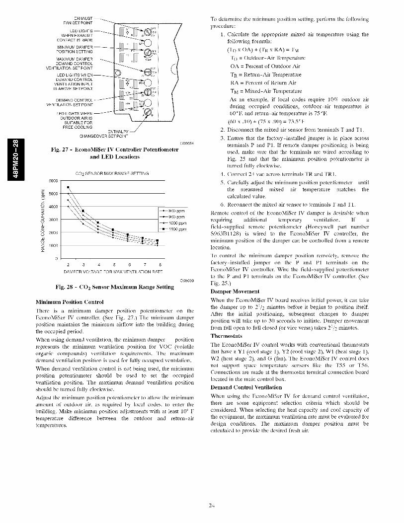
Fig. 27 - EconoMi$er IV Controller Potentiometerand LED Locations
C06034
Z
o_
CC
z
OLB
Z<CC
6OOO
5000
4000
3000
2000
1000
CO2 SENSOR MAX RANGE SEqq-ING
%
--*-- 800 ppm
___ --'-- 9O0 ppm
1000 ppm
--l-1100ppm
2 3 4 5 6 7 8
DAMPER VOLTAGE FOR MAX VENTILATION RATE
Fig. 28 - CO2 Sensor Maximum Range Setting
C06039
Minimum Position Control
There is a n_ininmm damper position potentiometer on theEconoMi$er IV controller. (See Fig. 27.) The n_ininmm damperposition maintains the minimum airflow into the building duringthe occupied period.
When using demand ventilation, the n_ininmm damper positionrepresents the minimum ventilation position fDr VOC (volatileorganic compounds) ventilation requirements. The maximumdemand ventilation position is used fDr fully occupied ventilation.
When demand ventilation control is not being used, the minimumposition potentiometer should be used to set the occupiedventilation position. The maximum demand ventilation positionshould be turned fully clockwise.
Adjust the minimum position potentiometer to allow the minimumamount of outdoor air, as required by local codes, to enter thebuilding. Make minimum position adjustments with at least 10° Ftemperature difference between the outdoor and return-airtemperatures.
TD determine the minimum position setting, perfDrm the fDllowingprocedure:
1. Calculate the appropriate mixed air temperature using thefDllowing fDrmula:
(To x OA) + (TR x RA) = TM
TO = Outdoor-Air TemperatureOA = Percent of Outdoor Air
TR = Return-Air TemperatureRA = Percent of Return Air
TM = Mixed-Air Temperature
As an example, if local codes require 10% outdoor airduring occupied conditions, outdoor-air temperature is60°F, and return-air temperature is 75°F.
(60 x .10) + (75 x .90) = 73.5°F2. Disconnect the mixed air sensor from terminals T and T1.
3. Ensure that the factory-installed jumper is in place acrossterminals P and P1. If remote damper positioning is beingused, make sure that the terminals are wired according toFig. 25 and that the n_ininmm position potentiometer isturned fully clockwise.
4. Connect 24 vac across terminals TR and TR1.
5. Carefully adjust the minimum position potentiometer untilthe measured mixed air temperature matches thecalculated value.
6. Reconnect the mixed air sensor to terminals T and T1.
Remote control of the EconoMi$er IV damper is desirable whenrequiring additional temporary ventilation. If afield-supplied remote potentiometer (Honeywell part number$963Bl128) is wired to the EconoMi$er IV controller, theminimum position of the damper can be controlled from a remotelocation.
TD control the minimum damper position remotely, remove thefactory-installed jumper on the P and P1 terminals on theEconoMi$er IV controller. Wire the field-supplied potentiometerto the P and P1 terminals on the EconoMi$er IV controller. (SeeFig. 25.)
Damper Movement
When the EconoMi$er IV board receives initial power, it can takethe damper up to 21/2 minutes before it begins to position itself.After the initial positioning, subsequent changes to damperposition will take up to 30 seconds to initiate. Damper movementfrom full open to full closed (or vice versa) takes 21/2 minutes.Thermostats
The EconoMi$er IV control works with conventional thermostats
that have aY1 (cool stage 1), Y2 (cool stage 2), Wl (heat stage 1),W2 (heat stage 2), and G (fan). The EconoMi$er IV control doesnot support space temperature sensors like the T55 or T56.Connections are made at the thermostat terminal connection boardlocated in the main control box.
Demand Control Ventilation
When using the EconoMi$er IV for demand control ventilation,there are some equipment selection criteria which should beconsidered. When selecting the heat capacity and cool capacity ofthe equipment, the maximum ventilation rate must be evaluated fordesign conditions. The maximum damper position must becalculated to provide the desired fresh air.
24
Typicallythe maximum ventilation rate will be about 5 to 10%
more than the typical cfm required per person, using normal
outside air design criteria.
A proportional anticipatory strategy should be taken with the
following conditions: a zone with a large area, varied
occupancy, and equipment that cannot exceed the required
ventilation rate at design conditions. Exceeding the required
ventilation rate means the equipment can condition air at a
maximum ventilation rate that is greater than the required
ventilation rate for maximum occupancy. A proportional
anticipatory strategy will cause the fresh air supplied to
increase as the room CO2 level increases even though the CO2 set
point has not been reached. By the time the CO2 level reaches the
set point, the damper will be at maximum ventilation and should
maintain the set point.
In order to have the CO2 sensor control the economizer damper in
this manner, first determine the damper voltage output forminimum or base ventilation. Base ventilation is the ventilation
required to remove contaminants during unoccupied periods. The
following equation may be used to determine the percent of
outside-air entering the building for a given damper position. For
best results there should be at least a 10 degree difference in outside
and return-air temperatures.
(To x OA) + (TR x RA) -- TM
TO = Outdoor-Air Temperature
OA = Percent of Outdoor Air
TR = Return-Air Temperature
RA = Percent of Return Air
TM = Mixed-Air Temperature
Once base ventilation has been determined, set the minimum
damper position potentiometer to the correct position.
The same equation can be used to determine the occupied or
maximum ventilation rate to the building. For example, an
output of 3.6 volts to the actuator provides a base ventilation rate
of 5% and an output of 6.7 volts provides the maximum ventilation
rate of 20% (or base plus 15 cfm per person). Use Fig. 28 to
determine the maximum setting of the CO2 sensor. For example, a
1100 ppm set point relates to a 15 cfm per person design. Use the
1100 ppm curve on Fig. 28 to find the point when the CO2 sensor
output will be 6.7 volts. Line up the point on the graph with the left
side of the chart to determine that the range configuration for the
CO2 sensor should be 1800 ppm. The EconoMi$er IV controller
will output the 6.7 volts from the CO2 sensor to the actuator when
the CO2 concentration in the space is at 1100 ppm. The DCV set
point may be left at 2 volts since the CO2 sensor voltage will be
ignored by the EconoMi$er IV controller until it rises above the
3.6 volt setting of the minimum position potentiometer.
Once the fully occupied damper position has been determined, set
the maximum damper demand control ventilation potentiometer to
this position. Do not set to the maximum position as this can result
in over-ventilation to the space and potential high-humidity levels.
CO2 Sensor Configuration
The CO2 sensor has preset standard voltage settings that can be
selected anytime after the sensor is powered up. (See Table 7.)
Use setting 1 or 2 for Carrier equipment. (See Table 7.)
1. Press Clear and Mode buttons. Hold at least 5 seconds until
the sensor enters the Edit mode.
2. Press Mode twice. The STDSET Menu will appear.
3. Use the Up/Down button to select the preset number. (See
Table 7.)
4. Press Enter to lock in the selection.
5. Press Mode to exit and resume normal operation.
The custom settings of the CO 2 sensor can be changed anytime
after the sensor is energized. Follow the steps below to change the
non-standard settings:
1. Press Clear and Mode buttons. Hold at least 5 seconds until
the sensor enters the Edit mode.
2. Press Mode twice. The STDSET Menu will appear.
3. Use the Up/Down button to toggle to the NONSTD menu
and press Enter.
4. Use the Up/Down button to toggle through each of the nine
variables, starting with Altitude, until the desired setting isreached.
5. Press Mode to move through the variables.
6. Press Enter to lock in the selection, then press Mode tocontinue to the next variable.
Dehumidification of Fresh Air with DCV Control
Information from ASHRAE (American Society of Heating,
Refrigeration, and Air Conditioning Engineers) indicates that the
largest humidity load on any zone is the fresh air introduced. For
some applications, a device such as a 62AQ energy recovery unit is
added to reduce the moisture content of the fresh air being brought
into the building when the enthalpy is high. In most cases, the
normal heating and cooling processes are more than adequate to
remove the humidity loads for most commercial applications.
This makes the control of the of the dehumidification device
simple when using the enthalpy or differential enthalpy sensor. The
enthalpy sensor or differential enthalpy sensor is installed on the
equipment to determine economizer operation. The high enthalpy
signal from the enthalpy sensor or differential enthalpy sensor can
be used to turn on the outdoor air moisture removal device any
time fresh air is required for the space.
The energy recovery device should be sized for maximum latent
and sensible conditioning at maximum ventilation on a design day.
A calculation for leaving-air temperature on a low ambient, low
ventilation day should also be done to determine the mixed-air
temperature of the return and pre-conditioned outside air. The
design should produce an air temperature somewhat near room
conditions to prevent reheat of the air mixture. The energy
recovery device should be interlocked with the heat to turn off thedevice when in the heat mode.
Operating Sequence
Cooling, Units Without Economizer
When the thermostat calls for one stage of cooling, Y1 and G are
energized. The indoor-fan contactor (IFC) and compressor
contactor C.A1 and outdoor-fan contactors (OFCI and OFC2
when outdoor temperature is above LTS setting) are energized andthe indoor-fan motor, compressor A1 and outdoor fans controlled
by OFCI are started. If the outdoor temperature is above the setting
of the low temperature switch, the outdoor fans controlled byOFC2 are also started.
If more cooling is required, the thermostat will call for a second
stage of cooling, energizing Y2. This in turn energizes the
compressor contactor C.B1. The second stage compressor is thenstarted.
25

Table7-CO2SensorStandardSettings
ANALOGSETTING EQUIPMENT OUTPUT OUTPUT
1
2
3
4
5
6
7
8
9
Interface w/StandardBuilding Control
System
Economizer
Health & Safety
Parking/Air Intakes/Loading Docks
Proportional
Proportional
Exponential
Proportional
Proportional
Exponential
Exponential
Proportional
Proportional
VENTILATIONRATE
(cfm/Person)
Any
Any
Any
15
2O
15
2O
0-10V4-20 mA
2-10V7-20 mA
0-10V4-20 mA
0-10V4-20 mA
0-10V4-20 mA
0-10V4-20 mA
0-10V4-20 mA
0-10V4-20 mA
0-10V4-20 mA
CO 2CONTROL
RANGE(ppm)
0-2000
0-2000
0-2000
0-1100
0-900
0-1100
0-900
0-9999
0-2000
OPTIONAL
RELAYSETPOINT
(ppm)
1000
1000
1100
1100
900
1100
900
5000
700
LEGEND
PPM -- Parts Per Million
RELAYHYSTERESIS
(ppm)
5O
5O
5O
5O
5O
5O
5O
5OO
5O
Heating_ Units Without Economizer
NOTE: 48PM20-28 units have 2 stages of heat.
When the thermostat calls for heating, power is sent to W on the
IGC (integrated gas unit controller) board. An LED (light-emitting
diode) on the IGC board will be on during normal operation. Acheck is made to ensure that the rollout switch and limit switch are
closed and the induced-draft motor is running. The induced-draft
motor is then energized, and when speed is proven with the hall
effect sensor on the motor, the ignition activation period begins.
The burners will ignite within 5 seconds.
If the burners do not light, there is a 22-second delay before
another 5-second attempt. If the burners still do not light, this
sequence is repeated for 15 minutes. After the 15 minutes have
elapsed, if the burners still have not lit, heating is locked out. To
reset the control, break 24-v power to the thermostat.
When ignition occurs the IGC board will continue to monitor the
condition of the rollout and limit switches, the hall effect sensor, as
well as the flame sensor. If the unit is controlled through a room
thermostat set for fan auto., 45 seconds after ignition occurs, the
indoor-fan motor will be energized (and the outdoor-air dampers
will open to their minimum position). If for some reason the
overtemperature limit opens prior to the start of the indoor fan
blower, on the next attempt, the 45-second delay will be shortenedto 5 seconds less than the time from initiation of heat to when the
limit tripped. Gas will not be interrupted to the burners and heating
will continue. Once modified, the fan on delay will not change
back to 45 seconds unless power is reset to the control.
When additional heat is required, W2 closes and initiates power to
the second stage of the main gas valve. When the thermostat is
satisfied, WI and W2 open and the gas valve closes, interrupting
the flow of gas to the main burners. If the call for Wl lasted less
than 1 minute, the heating cycle will not terminate until 1 minute
after Wl became active. If the unit is controlled through a room
thermostat set for fan auto., the indoor-fan motor will continue to
operate for an additional 45 seconds then stop (and the outdoor-air
dampers will close). If the overtemperature limit opens after the
indoor motor is stopped within 10 minutes of WI becoming
inactive, on the next cycle the time will be extended by 15 seconds.
The maximum delay is 3 minutes. Once modified, the fan off delay
will not change back to 45 seconds unless power is reset to thecontrol.
An LED indicator is provided on the IGC to monitor operation.
The IGC is located by removing the side panel and viewing the
IGC through the view port located in the control box access panel.
During normal operation, the LED is continuously on.
Cooling, Units With EconoMi$er IV
When free cooling is not available, the compressors will be
controlled by the zone thermostat. When free cooling is available,
the outdoor-air damper is modulated by the EconoMi$er IV
control to provide a 50 ° to 55°F mixed-air temperature into the
zone. As the mixed-air temperature fluctuates above 55 ° or
below 50°F, the dampers will be modulated (open or close) to
bring the mixed air temperature back within control.
If mechanical cooling is utilized with free cooling, the
outdoor-air damper will maintain its current position at the time
the compressor is started. If the increase in cooling capacity causes
the mixed-air temperature to drop below 45°F, then the
outdoor-air damper position will be decreased to the minimum
position. If the mixed-air temperature continues to fall, the
outdoor-air damper will close. Control returns to normal once the
mixed-air temperature rises above 48°F.
If optional power exhaust is installed, as the outdoor-air damper
opens and closes, the power exhaust fans will be energized and
deenergized.
If field-installed accessory CO2 sensors are connected to the
EconoMi$er IV control, a demand controlled ventilation strategy
will begin to operate. As the CO2 level in the zone increases above
the CO2 set point, the minimum position of the damper will be
increased proportionally. As the CO2 level decreases because of the
increase in fresh air, the outdoor-air damper will be proportionallyclosed.
For EconoMi$er IV operation, there must be a thermostat call for
the fan (G). This will move the damper to its minimum position.
When the EconoMi$er IV control is in the occupied mode and a
call for cooling exists (YI on the thermostat), the control will first
check for indoor fan operation. If the fan is not on, then cooling
will not be activated. If the fan is on, then the control will open the
EconoMi$er IV damper to the minimum position.
On the initial power to the EconoMi$er IV control, it will take the
damper up to 21/2 minutes before it begins to position itself. Any
change in damper position will take up to 30 seconds to initiate.
Damper movement from full closed to full open (or vice versa) will-_ 1take t etween 1 /2 and 21/2 minutes.
If free cooling can be used as determined from the appropriate
changeover command (switch, dry bulb, enthalpy curve,
differential dry bulb, or differential enthalpy), then the control will
modulate the dampers open to maintain the mixed-air temperature
set point at 50 ° to 55°F.
26

If there is a further demand for cooling (cooling second stage - Y2
is energized), then the control will bring on compressor stage 1 to
maintain the mixed-air temperature set point. The EconoMi$er IV
damper will be open at maximum position. EconoMi$er IV
operation is limited to a single compressor.
Heating_ Units With EconoMi$er IV
When the room temperature calls for heat, the heating controls are
energized as described in the Heating, Units Without Economizer
section. The IFM is energized and the EconoMi$er IV damper
modulates to the minimum position. When the thermostat is
satisfied and WI and W2 are deenergized, the IFM continues to
run, and the economizer damper modulates to the minimum
position.
SERVICE
ELECTRICALSHOCK HAZARD
Failure to follow this warning could result in personal
injury or death.
Before performing service or maintenance operations on
unit, turn off main power switch to unit.
UNIT OPERATION AND SAFETY HAZARD
Failure to follow this caution may result in personal iniury
or equipment damage.
Puron ® (R-410A) refrigerant systems operate at higher
pressures than standard R-22 systems. Do not use R-22
service equipment or components on Puron refrigerant
equipment.
FIRE, EXPLOSION HAZARD
Failure to follow this warning could result in personal
iniury, death and/or property damage.
Improper installation, adjustment, alteration, service, or
maintenance can cause property damage, personal
iniury, or loss of life. Refer to the User's Information
Manual provided with this unit for more details.
Do not store or use gasoline or other flammable vapors
and liquids in the vicinity of this or any other appliance.
What to do if you smell gas:1. DO NOT try to light any appliance.
2. DO NOT touch any electrical switch, or use any
phone in your building.
3. IMMEDIATELY call your gas supplier from a
neighbor's phone. Follow the gas supplier'sinstructions.
4. If you cannot reach your gas supplier, call the fire
department.
FIRE, EXPLOSION HAZARD
Failure to follow this warning could result in personal
iniury or death.
Disconnect gas piping from unit when pressure testing at
pressure greater than 0.5 psig. Pressures greater than
0.5 psig will cause gas valve damage resulting in hazardous
condition. If gas valve is subjected to pressure greater than
0.5 psig, it must be replaced before use. When pressure
testing field-supplied gas piping at pressures of 0.5 psig or
less, a unit connected to such piping must be isolated by
closing the manual gas valve(s).
Cleaning
Inspect unit interior at beginning of each heating and cooling
season and as operating conditions require. Remove unit top panel
and/or side panels for access to unit interior.
Coil Maintenance and Cleaning Recommendation
Routine cleaning of coil surfaces is essential to maintain proper
operation of the unit. Elimination of contamination and removal of
harmful residues will greatly increase the life of the coil and extend
the life of the unit. The following maintenance and cleaningprocedures are recommended as part of the routine maintenanceactivities to extend the life of the coil.
Remove Surface Loaded Fibers
Surface loaded fibers or dirt should be removed with a vacuum
cleaner. If a vacuum cleaner is not available, a soft non-metallic
bristle brush may be used. In either case, the tool should be applied
in the direction of the fins. Coil surfaces can be easily damaged (fin
edges can be easily bent over and damage to the coating of a
protected coil) if the tool is applied across the fins.
NOTE: Use of a water stream, such as a garden hose, against asurface loaded coil will drive the fibers and dirt into the coil. This
will make cleaning efforts more difficult. Surface loaded fibers
must be completely removed prior to using low velocity cleanwater rinse.
Periodic Clean Water Rinse
A periodic clean water rinse is very beneficial for coils that are
applied in coastal or industrial environments. However, it is very
important that the water rinse is made with very low velocity water
stream to avoid damaging the fin edges. Monthly cleaning asdescribed below is recommended.
Routine Cleaning of MicroChannel Condenser Coil Surfaces
To clean the MicroChannel condenser coil, chemicals are NOT to
be used; only water is approved as the cleaning solution. Only
clean potable water is authorized for cleaning Microchannel
condensers. Carefully remove any foreign objects or debris
attached to the coil face or trapped within the mounting frame &
brackets. Using a high pressure water sprayer, purge any soap or
industrial cleaners from hose and/or dilution tank prior to wettingthe coil.
27

Cleancondenserfaceby sprayingthecoilcoresteadilyanduniformlyfromtoptobottomdirectingthespraystraightintoortowardthecoilface.Donotexceed900psigora45degreeangle;nozzlemustbeatleast12"(30cm)fromthecoilface.Reducepressureandusecautiontopreventdamagetoaircenters(fins);donotfracturethebrazebetweenaircentersandrefrigeranttubes.Allowwatertodrainfromthecoilcoreandcheckforrefrigerantleakspriortostart-up.NOTE:PleaseseetheMicroChannelCondenserServicesectionforspecificinformationonthemicrochannelcoil.
EQUIPMENTDAMAGEHAZARDFailureto follow this caution may result in equipment damage.
High velocity water form a pressure washer, garden hose, orcompressed air should never be used to clean a coil. The force
of water or air jet will bend the fin edges and increase airside
pressure drop. Reduced unit performance or nuisance unit
shutdown may occur.
PERSONAL INJURY HAZARD
Failure to follow this caution may result in personal injury or
equipment damage.
Chemical cleaning should NOT be used on the aluminum
microchannel condenser. Damage to the coil may occur. Only
approved cleaning is recommended.
Routine Cleaning of Evaporator Coil Surfaces
Monthly cleaning with Totaline® environmentally sound coilcleaner is essential to extend the life of coils. This cleaner is
available from Carrier Replacement parts division as part number
P902-0301 for a one gallon container, and part number
P902-0305 for a 5 gallon container. It is recommended that
round-tube coils, including standard aluminum, pre-coated,
copper/copper or E-coated coils be cleaned with the Totaline
environmentally sound coil cleaner as described below. Coil
cleaning should be part of the unit's regularly scheduled
maintenance procedures to ensure long life of the coil. Failure to
clean the coils may result in reduced durability in the environment.
Avoid the use of:
• coil brighteners
• acid cleaning prior to painting
• high pressure washers
• poor quality water for cleaning
Totaline environmentally sound coil cleaner is non-flammable,
hypoallergenic, non-bacterial, and a USDA accepted
biodegradable agent that will not harm the coil or surrounding
components such as electrical wiring, painted metal surfaces, or
insulation. Use of non-recommended coil cleaners is strongly
discouraged since coil and unit durability could be affected.
Totaline Environmentally Sound Coil Cleaner Application
Equipment
• 21/2 gallon garden sprayer
• water rinse with low velocity spray nozzle
EQUIPMENT DAMAGE HAZARD
Failure to follow this caution may result in equipment damage.
Harsh chemicals, household bleach or acid or basic cleaners
should not be used to clean outdoor or indoor coils of any
kind. These cleaners can be very difficult to rinse out of thecoil and can accelerate corrosion at the fin/tube interface wheredissimilar materials are in contact. If there is dirt below the
surface of the coil, use the Totaline environmentally sound coilcleaner as described above.
Totaline Environmentally Sound Coil Cleaner ApplicationInstructions
1. Proper eye protection such as safety glasses is
recommended during mixing and application.
2. Remove all surface loaded fibers and dirt with a vacuum
cleaner as described above.
3. Thoroughly wet finned surfaces with clean water and a low
velocity garden hose, being careful not to bend fins.
4. Mix Totaline environmentally sound coil cleaner in a
21/2 gallon garden sprayer according to the instructions
included with the cleaner. The optimum solution
temperature is 100°F.
NOTE: Do NOT USE water in excess of 130°F, as the enzymatic
activity will be destroyed.
5. Thoroughly apply Totaline® environmentally sound coil
cleaner solution to all coil surfaces including finned area,tube sheets and coil headers.
6. Hold garden sprayer nozzle close to finned areas and apply
cleaner with a vertical, up-and-down motion. Avoid
spraying in horizontal pattern to minimize potential for fin
damage.
7. Ensure cleaner thoroughly penetrates deep into finned
areas.
8. Interior and exterior finned areas must be thoroughlycleaned.
9. Finned surfaces should remain wet with cleaning solutionfor 10 minutes.
10. Ensure surfaces are not allowed to dry before rinsing.
Reapplying cleaner as needed to ensure 10-minutesaturation is achieved.
11. Thoroughly rinse all surfaces with low velocity clean water
using downward rinsing motion of water spray nozzle.
Protect fins from damage from the spray nozzle.
Condensate Drain
Check and clean each year at the start of the cooling season. In
winter, keep drains and traps dry. An access panel is located above
the condensate connection to allow easy clean out of the
condensate pan. The first time the panel is removed, the insulation
behind the access panel will need to be cut away. Carefully cut theinsulation with a knife or blade on three sides so the insulation can
be folded out of the way during cleaning. Be careful not to damage
components behind the insulation while cutting. Once cleaning is
completed, fold the insulation back into place and secure the access
panel in the original position.
Filters
Clean or replace at start of each heating and cooling season, or
more often if operating conditions require. Refer to Table 1 for
type and size.
28
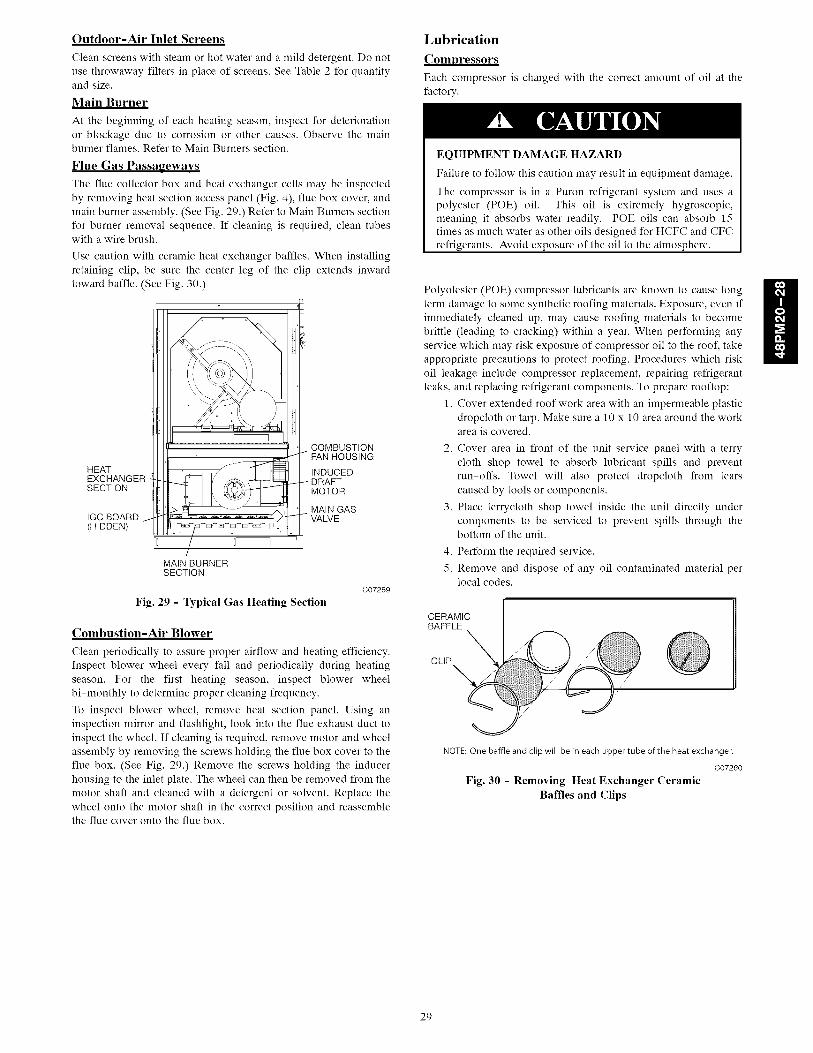
Outdoor-Air Inlet Screens
Clean screens with steam or hot water and a mild detergent. Do not
use throwaway filters in place of screens. See Table 2 for quantityand size.
Main Burner
At the beginning of each heating season, inspect for deterioration
or blockage due to corrosion or other causes. Observe the mainburner flames. Refer to Main Burners section.
Flue Gas Passageways
The flue collector box and heat exchanger cells may be inspected
by removing heat section access panel (Fig. 4), flue box cover, andmain burner assembly. (See Fig. 29.) Refer to Main Burners section
for burner removal sequence. If cleaning is required, clean tubeswith a wire brush.
Use caution with ceramic heat exchanger baffles. When installing
retaining clip, be sure the center leg of the clip extends inward
toward baffle. (See Fig. 30.)
HEATEXCHANGERSECTION
IGC BOARD(HIDDEN)
COMBUSTIONFAN HOUSING
INDUCEDDRAFTMOTOR
MAIN GASVALVE
/- :[ I/
MAIN BURNERSECTION
Fig. 29 - Typical Gas Heating Section
C07259
Combustion-Air Blower
Clean periodically to assure proper airflow and heating efficiency.
Inspect blower wheel every fall and periodically during heating
season. For the first heating season, inspect blower wheel
bi-monthly to determine proper cleaning frequency.
To inspect blower wheel, remove heat section panel. Using aninspection mirror and flashlight, look into the flue exhaust duct to
inspect the wheel. If cleaning is required, remove motor and wheel
assembly by removing the screws holding the flue box cover to the
flue box. (See Fig. 29.) Remove the screws holding the inducer
housing to the inlet plate. The wheel can then be removed from the
motor shaft and cleaned with a detergent or solvent. Replace thewheel onto the motor shaft in the correct position and reassemblethe flue cover onto the flue box.
Lubrication
Compressors
Each compressor is charged with the correct amount of oil at thefactory.
EQUIPMENT DAMAGE HAZARD
Failure to follow this caution may result in equipment damage.
The compressor is in a Puron refrigerant system and uses a
polyester (POE) oil. This oil is extremely hygroscopic,
meaning it absorbs water readily. POE oils can absorb 15times as nmch water as other oils designed for HCFC and CFC
refrigerants. Avoid exposure of the oil to the atmosphere.
Polyolester (POE) compressor lubricants are known to cause long
tern] damage to some synthetic roofing materials. Exposure, even if
immediately cleaned up, may cause roofing materials to become
brittle (leading to cracking) within a year. When performing any
service which may risk exposure of compressor oil to the roof, take
appropriate precautions to protect roofing. Procedures which risk
oil leakage include compressor replacement, repairing refrigerant
leaks, and replacing refrigerant components. To prepare rooftop:
1. Cover extended roof work area with an impermeable plastic
dropcloth or tarp. Make sure a 10 x 10 area around the workarea is covered.
2. Cover area in front of the unit service panel with a terry
cloth shop towel to absorb lubricant spills and prevent
run-offs. Towel will also protect dropcloth from tears
caused by tools or components.
3. Place terrycloth shop towel inside the unit directly under
components to be serviced to prevent spills through thebottom of the unit.
4. Perform the required service.
5. Remove and dispose of any oil contaminated material perlocal codes.
CERAMICBAFFLE
CLIP
NOTE: One baffle and clip will be in each upper tube of the heat exchanger.
C07260
Fig. 30 - Removing Heat Exchanger Ceramic
Baffles and Clips
H
29

Fan Shaft Bearings
Lubricate bearings at least every 6 months with suitable bearing
grease. Typical lubricants are given below:
MANUFACTURERTexacoMobil
SunocoTexaco
LUBRICANT
Regal AFB-2*Mobilplex EP No. 1
Prestige 42Multifak 2
*Preferred lubricant because it contains rust and oxidation inhibitors.
Fan Motor Bearings
Fan motor bearings are of the permanently lubricated type. Nofield lubrication is required. No lubrication of the condenser orevaporator motors are required.
Manual Outdoor Air Damper
If manual outdoor air damper blade adjustment is required, refer toStep 10 - Install Outdoor Air Hood section.
Economizer Adjustment
If economizer adjustment is required, refer to OptionalEconoMi$er IV section.
Evaporator Fan Service and Replacement
The 48PM units feature a slide-out fan deck for easy servicing ofthe indoor-fan motor, pulleys, belt, and bearings. To servicecomponents in this section, perform the following procedure:
1. Turn off unit power.
2. Open the fan section access panel.3. Remove three no. 10 screws at front of slide-out fan deck.
Save screws. (See Fig. 31.)
4. Disconnect the linfit switch wires located on the right sideof the fan deck. Other wires do not need to bedisconnected.
5. Fan deck can now be slid out to access serviceable
components.
EQUIPMENT DAMAGE HAZARD
Failure to follow this caution may result in equipment damage.
DO NOT SLIDE FAN DECK OUT PAST THE STOPBRACKET. If further access is required, the fan deck must besupported. Make sure plugs and wiring are not pinchedbetween fan housing and unit center post.
6. To replace fan deck to operating position, slide fan deckback into the unit. Secure with the three no. 10 screws
removed in Step 3.
7. Re-attach electrical plugs and wires.8. Close fan section access door.
9. Restore power to unit.
Evaporator Fan Performance Adjustment (See
Fig. 31 and 32.)
Fan motor pulleys are factory set for speed shown in Table 9.
To change fan speeds:
1. Shut off unit power supply.
2. Loosen nuts on the 4 carriage bolts in the mounting base.Using adjusting bolts and plate, slide motor and removebelt.
3. Loosen movable-pulley flange setscrew. (See Fig. 32.)
4. Screw movable flange toward fixed flange to increase speedand away from fixed flange to decrease speed.Increasing fan speed increases load on motor. Do notexceed maximum speed specified in Table 9.See Table 6 for air quantity linfits.
5. Set movable flange at nearest keyway of pulley hub andtighten setscrew. (See Table 9 for speed change for each fullturn of pulley flange.)
6. Replace and tighten belts (see Evaporator Fan Belt TensionAdjustment section below).
7. Restore power to unit.
To align fan and motor pulleys:
1. Loosen fan pulley setscrews.
2. Slide fan pulley along fan shaft.
3. Make angular alignment by loosening motor frommounting plate.
Evaporator Fan Belt Tension Adjustment
To adjust belt tension:
1. Turn off unit power.
2. Slide out fan deck to service position as shown inEvaporator Fan Service and Replacement section above.
3. Loosen fan motor bolts.
4. Move motor mounting plate to adjust to proper belt tension.(See Table 8.) Motor adjuster bolts may be used to tightenbelts. (See Fig. 31.)
5. Check for proper belt alignment. Adjust if necessary.
6. Tighten motor mounting plate bolts to lock motor in properposition.
7. Return fan deck back into operating position.
8. Restore power to unit.
FANPULLEY-
LIMITSWITCH
CONNECT
MOTORPULLEY(HIDDEN)
MOTOR
MOUNTINGBASE
SLIDE-OUTFAN DECK
C08046
Fig. 31 - Evaporator-Fan Motor Adjustment
3O

Table8 - Belt Tension Adjustment
BEN TENSION (Ib)
48PM VOLTAGE UnitModelNumberPositionlO
A,J B,K C,L D,M E,N _P G,Q H,R
230 4.8 5.1 5.6 4.5 NA 4.7 5.0 5.520 460 4.8 5.1 5.6 4.5 NA 4.7 5.0 5.5
575 5.3 5.1 5.6 4.5 NA 5.2 5.0 5.5230 4.8 5.1 5.6 4.5 NA 4.7 5.0 5.5
24 460 4.8 5.1 5.6 4.5 NA 4.7 5.0 5.5
575 5.3 5.1 5.6 4.5 NA 5.2 5.0 5.5
230 4.5 5.4 5.9 4.5 4.5 5.4 5.9 4.528 460 4.5 5.4 5.9 4.5 4.5 5.4 5.9 4.5
575 4.5 5.4 5.9 4.5 4.5 5.4 5.9 4.5
STRAIGHT EDGE MUST
WITH BELT
MOFOR AND FANSHAFTS MUST BEPARALLEL
MOVABLEFLANGE
SETSCREWS_
FIXED FLANGE
SINGLE-GROOVE
EQUIPMENT DAMAGE HAZARD
Failure to follow this caution may result in equipment damage.
Do not use MCHX coils in severe coastal or industrialenvironments.
TUBES
FINS
IH
Fig. 32 - Evaporator-Fan Alignmentand Adjustment
C07075
Condenser-Fan Adjustment (Fig. 33)
1. Shut off unit power supply.
2. Remove condenser-fan assembly (grille, motor, motor
cover, and fan) and loosen fan hub setscrews.
3. Adjust fan height as shown in Fig. 33.
4. Tighten setscrews and replace condenser-fan assembly.
5. Turn on power to unit.
C07204
Fig. 33 - Condenser-Fan Adjustment
MCHX Condenser Service and Replacement
The condenser coil in this unit is a MicroChannel Heat Exchanger
(MCHX) surface. The MCHX is an all-aluminum constructionwith fins over a single-depth crosstube. The crosstubes have
multiple small passages through which the refrigerant passes from
header to header on each end. (See Fig. 34.) The all-aluminumconstruction provides increased resistance to corrosion over
aluminum fins on copper tubes in normal and mild marine
applications.
MANIFOLD
MICROCHANNELS
C07273
Fig. 34 - Microchannel Coils
Repairing Tube Leaks
RCD offers service repair kits for repairing tube leaks in the
crosstubes. These kits include approved braze materials and
instructions specific to the aluminum microchannel coil.
EQUIPMENT DAMAGE HAZARD
Failure to follow this caution may result in equipment damage.
Use of other than approved repair procedures may affect the
pressure rating or the corrosion resistance of the microchannelcondenser coil.
Replacing the MCHX Coil
The service replacement coil is preformed and is equipped with
transition joints with copper stub tubes. When brazing the
connection joints to the unit tubing, use a wet cloth around the
aluminum tube at the transition joint. Avoid applying torch flame
directly onto the aluminum tubing.
31

Verify Sensor Performance
(]sing an ohmmeter and a thernmmeter, compare measuredtemperature to the resistance shown in Table 9.
Table 9 - Sensor Temperature/Resistance Values
TEMPERATURE(F)
-58
-40
-22
-4
14
32
50
68
77
86
104
122
140
158
176
185
194
212
230
248
257
266
284
302
RESISTANCE (ohms)
200,250
100,680
53,010
29,091
16,590
9,795
5,970
3,747
3,000
2,416
1,597
1,080
746
525
376
321
274
203
153
116
102
89
70
55
Economizer Operation During Power Failure
Dampers have a spring return. In event of power failure, damperswill return to fully closed position until power is restored. Do notmanually operate damper motor
Evacuation
Proper evacuation of the system will remove noncondensables andensure a tight, dry system before charging. Evacuate from bothhigh and low side ports. Never use the system compressor as avacuum pump. Refrigerant tubes and indoor coil should beevacuated to 500 nficrons. Always break a vacuum with drynitrogen. The two possible methods are the deep vacuum methodand the triple evacuation method
Deep Vacuum Method
The deep vacuum method requires a vacuum pump capable ofpulling a minimum vacuum of 500 nficrons and a vacuum gaugecapable of accurately measuring this vacuum depth. The deepvacuum method is the most positive way of assuring a system isfree of air and liquid water. (See Fig. 35.)
Triple Evacuation Method
The triple evacuation method should only be used when vacuumpump is capable of pumping down to 28-in. of mercury andsystem does not contain any liquid water. Proceed as follows:
1. Pump system down to 28-in. of mercury and allow pumpto continue operating for an additional 15 nfinutes.
2. Close service valves and shut off vacuum pump.
3. Connect a nitrogen cylinder and regulator to system andopen until system pressure is 2 psig.
4. Close service valve and allow system to stand for 1 hr.During this time, dry nitrogen will be able to diffusethroughout the system, absorbing moisture.
5. Repeat this procedure. System will then contain nfinimalamounts of contanfinants and water vapor.
5000 --
4500 =
4000 =
3500 =
3000 =
0 2500 =i
2000 =
1500 =
1000 =
500 =
J
!==d
I
m
m
m
m
m
l
m
0 1 2 3 4 5 6 7
MINUTES
Fig. 35 - Deep Vacuum Graph
DRY SYSTEM
C06264
Refrigerant Charge
Amount of refrigerant charge is listed on unit nameplate. Refer toCarrier GTAC II; Module 5; Charging, Recovery, Recycling, andReclamation section for charging methods and procedures. []nitpanels nmst be in place when unit is operating during chargingprocedure.
Puron® (R-410A) refrigerant cylinders contain a dip tube whichallows liquid refrigerant to flow from the cylinder in an uprightposition. Charge units with cylinder in the upright position and acommercial type metering device in the manifold hose.
[]NIT OPERATION AND SAFETY HAZARD
Failure to follow this caution may result in personal iniuryor equipment damage.
This unit uses Puron ® (R-410A) refrigerant system whichoperate at higher pressures than R-22 or other systems. Noother refrigerant may be used in this system. Gauge set,hoses, and recovery system nmst be designed to handlePuron refrigerant. If unsure about equipment, consult theequipment manufacturer.
NOTE: Do not use recycled refrigerant as it may containcontanfinants.
No Charge
Use standard evacuating techniques. After evacuating system,
weigh in the specified amount of refrigerant (refer to unit
nameplate).
Low Charge Coolin_
[]sing cooling charging chart (see Fig. 36-38), add or remove
refrigerant until conditions of the chart are met. An accurate
pressure gage and temperature-sensing device are required.
Charging is accomplished by ensuring the proper amount of liquid
subcooling. Measure liquid line pressure at the liquid line service
valve using pressure gauge. Connect temperature sensing device to
the liquid line near the liquid line service valve and insulate it so
that outdoor ambient temperature does not affect reading.
32

PM28 CHARGING CHART - R410A REFRmGERANTCOOLING MODE - ALl- OUTDOOR FANS MUST BE RUNNmNG
6O
40
2O
O0
8C
6C
4E
2C ...........
100 150 200 250 300 350 4.00 450 500 550 600
Compressor Discharge Pressure, [psig]
Fig. 36 - Charging Chart - 48PM28
C08049
PM20 CHARGING CHART - R410A REFRIGERANTCOOLINGMODE- ALL OUTDOORFANSMUST BE RUNNING
2(
100 150 200 250 300 350 400 450 500 550 600
Compressor Discharge Pressure, [psigl
Fig. 37 - Charging Chart - 48PM20
C08047
To Use the Cooline Chareine Chart
Use the above temperature and pressure readings, and find the
intersection point on the cooling charging chart. If intersection
point on chart is above line, add refrigerant. If intersection point on
chart is below line, carefully recover some of the charge. Recheck
suction pressure as charge is adjusted.
NOTE: Indoor-air cfm must be within normal operating range of
unit. All outdoor fans must be operating.
The TXV (thermostatic expansion valve) is set to maintain between
10 and 15 degrees of superheat at the compressors. The valves are
factory set and cannot be adjusted. Do not use a TXV designed for
use with R-22 refrigerant.
160
]40
120
too
4(
2(
Ioo 150
PM24 CHARGING CHART - R410A REFRIGERANTCOOLING MODE - ALL OUTDOOR FANS MUST _ RUNNING
IJ_ll IIIIIIII_1111 IIIIIIII
IIIIIIIIIIII
200 250 300 350 400 450 500 550
Corapressor Discharge Pressure, Ipsig]
,m
,m
,m
,m
,4
:=
:=
im
im
im
im
,1!600
Fig. 38 - Charging Chart - 48PM24
C08048
Puron ® Refrigerant
Puron refrigerant operates at 50 to 70 percent higher pressures than
R-22. Be sure that servicing equipment and replacement
components are designed to operate with Puron refrigerant. Do not
mix with components that have been used with other refrigerants.
Puron refrigerant, as with other HFCs, is only compatible withPOE oils.
Recovery cylinder service pressure rating must be 400 psig. Puron
systems should be charged with liquid refrigerant. Use a
commercial-type metering device in the manifold hose. Manifold
sets should be 750 psig high-side and 200 psig low-side with 520
psig low-side retard. Use hoses with 750 psig service pressure
rating. Leak detectors should be designed to detect HFC
refrigerant.
Gas Valve AdjustmentNatural Gas
The gas valve opens and closes in response to the thermostat orlimit control.
When power is supplied to valve terminals W2 (High Fire) and C1,
the main valve opens to its preset position.
The regular factory setting is stamped on the valve body. The
setting is 3.00-in. wg for vertical supply/discharge units. The
setting is 2.95-in. wg for horizontal supply/discharge units.
To adjust regulator:
1. Set unit at setting for no call for heat.
2. Turn main gas valve to OFF position.
3. Remove 1/8-in. pipe plug from manifold or gas valve
pressure tap connection. Install a suitable pressure-
measuring device.
4. Set main gas valve to ON position.
5. Set thermostat at setting to call for heat.
6. Remove screw cap covering regulator adjustment screw.
(See Fig. 39.)
7. Turn adjustment screw clockwise to increase pressure or
counterclockwise to decrease pressure.
8. Once desired pressure is established, set unit setting for no
call for heat, turn off main gas valve, remove
pressure-measuring device, and replace 1/8-in. pipe plug
and screw cap.
H
33

2 LEADS, #18 WIRE 1/32 INSULATION, REGULATOR600V. MAX., 105°C _ ADJUSTMENT SCREW
(REMOVE COVER)/HI[ \_\ / OUTLET PRESSURE
/u_u_ }}\\ / /TAP (PLUGGED)
__ 1/8-27N.P.T. THDS.
I RI'="f_L_. '_ I:_ln_l n_oll=_l RECEPTACLEAND
_/____ TABCObMLB'NAT'ON
\ I _¢_)J "_"1 _ou==:_/I_) '",PILOT CONNECTION\ .... / _ " FOR 1/4" O.D. TUBING
INLET PRESSURE TAP / (PLUGGED)(PLUGGED) /1/8- 27 N.P.T. THDS. RECEPTACLE TERMINAL
C07262
Fig. 39 - Gas Valve
High Altitude
For high altitude applications greater than 2000 fl the heat inputrate should be reduced. The higher the altitude is above sea level,the less oxygen is in the air. See Table 10 for orifice sizing. A highaltitude kit is available to convert unit for altitudes up to 7,000 ft.
Main Burners
For all applications, main burners are factory set and should requireno adjustment.Main Burner Removal
1. Shut off (field-supplied) manual main gas valve.
2. Shut off power to unit.
3. Remove gas section access panel.
4. Disconnect gas piping from gas valve inlet.
5. Remove wires from gas valve.6. Remove wires from rollout switch.
7. Remove sensor wire and ignitor cable from IGC board.
8. Remove 2 screws securing manifold bracket to basepan.
9. Remove 2 screws that hold the burner assembly to vestibuleplate.
10. Lift burner/manifold assembly out of unit.
Cleaning and Adjustment
1. Remove burner rack from unit as described in Main BurnerRemoval section above.
2. Inspect burners, and if dirty, remove burners from rack.
3. Using a soft brush, clean burners and crossover port asrequired.
4. Adjust spark gap. (See Fig. 40.)5. Reinstall burners on rack.
6. Reinstall burner rack as described above.
Filter Drier
Replace whenever refrigerant system is exposed to atmosphere.Only use factory specified liquid-line filter driers with workingpressures no less than 650 psig. Do not install a suction-line filterdrier in liquid line. A liquid-line filter drier designed for use withPuron® refrigerant is required for each circuit.
Protective Devices
Compressor Protection
Overcurrent
Each compressor has internal line break motor protection.
Overtemperature
Each compressor has an internal protector to protect it againstexcessively high discharge gas temperatures.
High-Pressure Switch
If the high-pressure switch opens, the compressor will shut downand the compressor lockout (CLO) device will energize to blockfurther compressor operation. The high-pressure switch will resetautomatically as the refrigerant pressure drops below its reset level.The CLO will remain energized until manually reset or coolingdemand is removed.
Low-Pressure Switch
If the low-pressure switch opens, the compressor will shut downand the compressor lockout (CLO) device will energize to blockfurther compressor operation. The low-pressure switch will resetautomatically as the refrigerant pressure rises above its reset level.The CLO will remain energized until manually reset or coolingdemand is removed.
Freeze Protection Switch
This switch is installed on each ev@orator coil section to provideprotection against continued unit operation with a frostedevaporator surface. If the freeze protection switch opens, thecompressor on this circuit will shut down and the compressorlockout (CLO) device will energize to block further compressoroperation. The freeze protection switch will reset as the evaporatortube temperature rises above its reset level. The CLO will remainenergized until manually reset or cooling demand is removed.
Compressor Lockout (CLO) Device
The CLO prevents automatic recycling of the compressor as safetycontrols reset. If the high-pressure switch, low-pressure switch orfreeze protection switch opens, the CLO device will energize toblock further compressor operation. To reset the CLO (after allsafety switches have reset), either open the thermostat to removethe cooling demand signal (and then re-close) or cycle the controlpower in the unit.
Evaporator Fan Motor Protection
A manual reset, calibrated trip, magnetic circuit breaker protectsagainst overcurrent. Do not bypass connections or increase the sizeof the breaker to correct trouble. Determine the cause and correct it
before resetting the breaker.
Condenser-Fan Motor Protection
Each condenser-fan motor is internally protected againstovertemperature.
Fuses are also located in the control box and feed power to thecondenser fan motors. Always replace blown times with the correctsize time as indicated on the unit time label.
Relief Devices
All units have relief devices to protect against damage fromexcessive pressures (i.e., fire). These devices protect the high andlow side and are located at the suction line service port. Protectjoint during brazing operations near joint.
Control Circuit, 24-V
Each control circuit is protected against overcurrent by a 3.2 ampcircuit breaker. Breaker can be reset. If it trips, determine cause oftrouble before resetting. See Fig. 41-44 for schematics.
Replacement Parts
A complete list of replacement parts may be obtained from anyCarrier distributor upon request.
Diagnostic LEDs
The IGC control board has a LED for diagnostic purposes. SeeUnit Troubleshooting section for more information.
34

.---'SEE DETAIL"C"
[
[
[I
SPARK GAP.120"TO.140"
SPARK GAP, 181"
DETAIL "C"
Fig. 40 - Spark Gap Adjustment
C07263
Table 10 - Altitude Compensation*
NATURAL GAS
ELEVATION NATURAL GAS ORIFICE SlZEt
(ft) Low Heat Medium Heat High Heat (8 Cell) High Heat (8 Cell)
0-1,999 29 30 29 29
2,000 29 30 29 29
3,000 30 31 30 30
4,000 30 31 30 30
5,000 30 31 30 30
8,000 30 31 30 30
7,000 31 32 31 31
8,000 31 32 31 31
9,000 31 32 31 31
10,000 32 33 32 32
*As the height above sea level increases, there is less oxygen per cubic foot of air. Therefore, heat input rate4% input reduction per each 1000 ft.
1-Orifices available through the local Carrier dealer.
should be reduced at higher altitudes. Includes a
PROPANE GAS
ELEVATION PROPANE GAS ORIFICE SIZEt
(ft) Low Heat Medium Heat High Heat (8 Cell)
0-1,999 35 38
2,000 36 39
3,000 36 39
4,000 37 40
5,000 37 40
8,000 38 41
7,000 39 42
8,000 40 43
9,000 41 44
10,000 42 45
*As the height above sea level increases,4% input reduction per each 1000 ft.
there is less oxygen per cubic foot of
High Heat (8 Cell)
35 35
36 36
36 36
37 37
37 37
38 38
39 39
40 40
41 41
42 42
should be reduced at higher altitudes. Includes aair. Therefore, heat input rate
1-Orifices available through the local Carrier dealer.
35

SE_OWE_SCHE_ATZC LOW VOLTAGE CONTROL
_OFFHE_T
......° COOL
(
FIELD THERMOSTAT
I
_L_ b
_ .........................................<< .......PLS 6
OR_ /
I
OR E THALe_ 1S INSIALLED
50TG505330 Rev.2.0
Fig. 41 - Typical Low Voltage Control Schematic
C08050
36

_BLK ................................
--YEL _'1€92 _-_ YELEL ............................-
MOVE WIRES TO OEC1WHEN INSIALLIN6 LOW_=_"_=_ -....--_AMBIENT iAP CONTROL
ACCESSORY
ADO WIRES WHEN INSTALLENGLOW ANBIENT FAN CONTROL_-_
ACCESSORY _
CONNECT WIRE TO BLK
APPROPRIATE UNIT VOLTAGE 1
_RLNWL_ ...........................................] TRAP!
............
CONNECTWIRE TOAPPROPREATE UNI_ VOL#AGE
.....................................................BLH ...................................................I TRAN2[
............
POWER SCHEMATIC
CAI _)
FFTICLO AI COMP AI
___LU
_ CCH A1CA AUX C.AI DU2
H --5335 Rev. 2.0
Fig. 42 - Typical Power Schematic
C08051
3?

,..QO0
I
I
,S
0FC2 I_qoEOUIP
_ GROUND
OISCONNECT
_ACRBREAKER
Ei
7
COMPONENT
CLO A_
D
ARRANGEMENT
'O'E'CO""_<_<EO_,_E_J CONTROLBOXONIOFFSWITCH
COMPRESSOR CONTACTORS
ENTUALPYSAT. OEMS (24,28 ONLYI
CONDENSERCOILSTHERMISTORLOCATIONS(READ REND)
F ANOAk, 'RNT_Y _ONTROL
\
FREEZESTAT LOCATIONSFVAPORATORRETU_ BENDENO
X_SPEED CONFROL
THERMISTOR LOCATION
PLUG LOCATION REFERENCE
eLI
PL3 HEAT SECTION PARTITION(HEAT CONTROLS)
FAN SECTIONPL4 INDOOR EAN MOTOR}
CONDENSERSECTIONPL5 (OEM1, B, B)
PL6 CONDENSER_CTiON{OFM4, 5,
PLY ECONOMIZER SECTION(ECONOMIZER MO[ORIPOWEREXHAUST SECTION
PL9 (POWER EXNAUS] MOTORS)
PLIO CONDENSERSECTION__ (OFM1)
PLII CONDENSERSECTION(OFMR)
PL12 CONDENSER SECTION(OFM3)
PLIR CONDENSER SECTION(OFM4)
PLIa CONDENSER SECTION(OFW5)
PL15 CONDENSERSEEIlON(OFM6)
FAN SECTIONPLI6 (FAN STATUS ACCESSORY)
PLIY ECONOWIZERSECTION(R-POSITION HAMPER)
Do0Q
oo)
SMOKECONTROL :
EET _CONVE_d'ENCE
TERM MAL BLOCKo TERMINAL (UNMARKED)
ERM MAL _MARKED° SPLICE
FACIORY WIRINGFIELD WIRINGlO INDICATE COMMON POTENT ALONL V, NOT TO REPRESENT WIRING
• -- 0 NDICATE FlOP OR ACCESSORY
i/
FA_NST'A_ SMOKE CON[R"_'mL:
,, C_NI'ENCE NPSBLPS A _ER SY_T'_'_'_ TRAN_FO_ CCHBI
GAS HEATN_ EVAP CIRCUIT CONFIGURATION AUAX CIRCUIT A FU FUSEAUX]LLARY CONTACT GNB GROUNDNOTES: AL AMBIENT LIMIJ GV GAS VALVEI, FACTORY WIRING [S IN ACCORDANCEWITH THE NATIONAL _B CIRCUIT B HPS NIGH PRESSURE SWITCH
ELECTRICAL CODES ANY FIELD MODIFICATIONS OR C CIRCUIT C I IGNITORADDiT!ONS MUST BE IN COMPLIANCE WITH ALL APPLICABLE _r COMPRESSOR,CONTACTOR IAQ INDOOR AIR QUALITYCODES CAP CAPACITOR IOM INDUCED BRAF[ MOTOR
2 USE 7S°C MiN WIRE FOR FIELD POWERSUPPLY, USE COPPER CD CIRCUIT BREAKER IDR INDUCED DRAFT RELAYWIRES FOR ALL UNITS CCH CRANNCASE HEATER IEC INDOOR FAN CONTACTOR
B ALL CIRCUIT BREAKERS "MUST TRi ° AMPS" ARE EQUAL TO CLO COMPRESSORLOCKOUT IECB INDOOR FAN CIRCUIT BREAKEROR LESS THAN IS6% RLA COMP COMPRESSOR INN INDOOR FAN MOTOR
4 COMPRESSORAND FAN MOTORSARE THERMALLY PROTECTED-- CR CONTROLRELAY ]RN INDOOR RELATIVE HUMIDITYTHREE PHASE NO[ORS PROTECTEDAGAINST PRIMARY SINGLE DU DUMMY [ERMiNAL ICE INIEGRATEB GAS CONTROLLERPHASECONDITIONS ECB ECONOMIZER CONTROLBOARD LPS LOW PRESSURE SWITCH
5 THE CLO LOCKS OUT THE COMPRESSORTO PREVENT SHORT ECS FAN CYCLING SWITCH LS LIMIJ SWlTCNCYCL]NG ON COMPRESSOROVERLOAD AND SAFETY DEVICES; RPT FREEZE PROTECTION THERMOSTAT ORE OUTDOORFAN CONTACTORBEFORE REPLACING ELO, CHECK THESE DEVICES ES iLAME SENSOR
• SUPPLY' _MONE
_AN ,SIATUS_ OUT ET TRANSFORMERCCHAI LPS A [VAP CIRCUIT CONFIGURATION _ '' _)U[_ • ,J
ELECTRIC/NOHEAT ONLY _F(T_I__"_'?'s_T_
OFM OUTDOORFAN MOTOR TMERMOSTAT/IQC MARKINGSORN OUTDOORRELATIVE HUMiDiTY BM BLOWER MOTOR Wl _sf STAGE OE HEATINGPEE POWEREXHAUST CONIAE[OR C COMMON W2 Bnd STAGE OF HEATINGPEN POWEREXHAUST MOTOR CM INDUCER MOEOR X ALARM OUTPUTPL PLUG CS CENTRIFUGAL SWITCH Y1 ]s_ STAGE OF COOLINGPLP PHASE LOSS PROTECTION G FAN Y2 2ridSTAGE OF CO0{]NGRAT RUURN AIR SENSOR iFO INDOOR FAN ONRS ROLLOUT SWITCH L1 LINE 1SAT SUPPLY AIR TEMPERATURE R THERWOSTATPOWERSS SPEED SENSOR ([DM) R] POWER SUPPLYTB TERM[NA_ BLOCR SS SPEED SENSORTBR TIME DELAY RELAY W THERMOSTATHEAT
TRAN TRANSEORMER
50TG505337 Rev. 2,0

TROUBLESHOOTING
Unit Troubleshooting
Refer to Tables 11-12 and Fig. 44.
Table 11 - Cooling Service Analysis
PROBLEM CAUSE REMEDY
Compressor and Condenser Power failure. Call power company.Fan Will Not Start. Fuse blown or circuit breaker tripped. Replace fuse or reset circuit breaker.
Defective thermostat, contactor, transformer, or control Replace component.relay.
Insufficient line voltage. Determine cause and correct.
Incorrect or faulty wiring. Check wiring diagram and rewire correctly.
Thermostat setting too high. Lower thermostat setting below room temperature.Compressor Will Not Start Faulty wiring or loose connections in compressor Check wiring and repair or replace.but Condenser Fan Runs. circuit.
Compressor motor burned out, seized, or internal Determine cause. Replace compressor.overload open.
Defective overload. Determine cause and replace.
Compressor locked out Determine cause for safety trip and reset lockout.One leg of 3-phase power dead. Replace fuse or reset circuit breaker.
Determine cause.
Compressor Cycles Refrigerant overcharge or undercharge. Recover refrigerant, evacuate system, and recharge to(other than normally nameplate.satisfying thermostat). Defective compressor. Replace and determine cause.
Insufficient line voltage. Determine cause and correct.Blocked condenser. Determine cause and correct.
Defective overload. Determine cause and replace.
Defective thermostat. Replace thermostat.Faulty condenser-fan motor. Replace.
Restriction in refrigerant system. Locate restriction and remove.Compressor Operates Dirty air filter. Replace filter.continuously. Unit undersized for load. Decrease load or increase unit size.
Thermostat set too low. Reset thermostat.
Low refrigerant charge. Locate leak, repair, and recharge.
Air in system. Recover refrigerant, evacuate system, and recharge.
Condenser coil dirty or restricted. Clean coil or remove restriction.Excessive Head Pressure. Dirty air filter. Replace filter.
Dirty condenser coil. Clean coil.
Refrigerant overcharged. Recover excess refrigerant.Faulty TXV. 1. Check TXV bulb mounting and secure tightly to suction line.
2. Replace TXV if stuck open or closed.
Air in system. Recover refrigerant, evacuate system, and recharge.Condenser air restricted or air short-cycling Determine cause and correct.
Head Pressure Too Low. Low refrigerant charge. Check for leaks, repair, and recharge.Restriction in liquid tube. Remove restriction.
Excessive Suction Pressure. High heat load. Check for source and eliminate.
Faulty TXV. 1. Check TXV bulb mounting and secure tightly to suction line.2. Replace TXV if stuck open or closed.
Refrigerant overcharged. Recover excess refrigerant.
Suction Pressure Too Low. Dirty air filter. Replace filter.Low refrigerant charge. Check for leaks, repair, and recharge.
Metering device or low side restricted. Remove source of restriction.
Faulty TXV. 1. Check TXV bulb mounting and secure tightly to suction line.2. Replace TXV if stuck open or closed.
Insufficient evaporator airflow. Increase air quantity. Check filter and replace if necessary.
Temperature too low in conditioned area. Reset thermostat.Field-installed filter drier restricted. Replace.
LEGEND
TXV -- Thermostatic Expansion Valve
39

PROBLEMBurners Will Not Ignite.
Inadequate Heating.
Poor Flame Characteristics.
Table 12 - Gas Heating Service Analysis
CAUSE
Misaligned spark electrodes.
No gas at main burners.
Water in gas line.No power to furnace.
No 24 v power supply to control circuit.
Miswired or loose connections.
Burned-out heat anticipator in thermostat.Broken thermostat wires.
Dirty air filter.Gas input to unit too low.
Unit undersized for application.Restricted airflow.
Blower speed too low.
Limit switch cycles main burners.
Too much outdoor air.
Incomplete combustion (lack of combustion air)results in:
Aldehyde odors, CO, sooting flame, or floatingflame.
Burners Will Not Turn Off. Unit is locked into Heating mode for a one minuteminimum.
REMEDY
Check flame ignition and sensor electrode positioning.Adjust as needed.
Check gas line for air; purge as necessary. After purging gas lineof air, allow gas to dissipate for at least 5 minutes before attempt-ing to relight unit.
Check gas valve.
Drain water and install drip leg to trap water.Check power supply, fuses, wiring, and circuit breaker.
Check transformer. Transformers with internal overcurrent protec-tion require a cool-down period before resetting. Check 24-v circuitbreaker; reset if necessary.
Check all wiring and wire nut connections.
Replace thermostat.Run continuity check. Replace wires if necessary.
Clean or replace filter as necessary.Check gas pressure at manifold. Clock gas meter for input.If too low, increase manifold pressure or replace with correct ori-fices.
Replace with proper unit or add additional unit.
Clean filter, replace filter, or remove any restrictions.
Install alternate motor, if applicable, or adjust pulley to increase fanspeed.
Check rotation of blower, thermostat heat anticipator settings, andtemperature rise of unit. Adjust as needed.
Adjust minimum position.
Check economizer operation.
Check all screws around flue outlets and burner compartment.Tighten as necessary.
Cracked heat exchanger. Replace heat exchanger.
Overfired unit -- reduce input, change orifices, or adjust gas lineor manifold pressure.
Check vent for restriction. Clean as necessary.
Check orifice to burner alignment.Wait until mandatory one minute time period has elapsed or powerto unit.
40

1 FLASH - INDOOR FN_I DELAY(HF-ATiNG)
2 _8 - OPENING OF U_'f8WR'(;H
3 F_ - FLAME SENSO_iNDICATES F_
CLOSED GAS VALVE
4 F[AS'E8 - LIMIT 8wrrcHCYCLED 4, ']IMES ON 8_,GtdE
I 5 _8 - _ LOCKOUT
FAULT(No _r_ ftern _ H_
Sens_ for e0 _)
F-F-F
7 F_S - OPENING Of=ROLLObrF 8WITCH
8 FL_.SHES - _ ORFALLT
F-
F-
F-9 FLASHES - SOFTWARE FLOCKOUT
]]
[
i'Wl' FROM BASE CONTROL BOARD ENERGIZES 'W'ON IGC - 1 MINUTE LOCK-ON
COMBUSTION I:_Y ON IGC 18 ENEI_ IJ
EFFECT SENSOR 8ENDS CORRECT &'GNAt. TO _ 'Jl' ON IGC
IGC HIGH VOLTAGE"fl_kN,._FORMFJ_ CREATES A
!0,000 VOLT 8PARK R3_ 58EX)ND8
I
OFF GAS VALVE AND SPARK
[ HA8 BEEN REDUCED DLE TO _ b%MTCH 1
/ m,=s)_ _LL_ _o_ .a_Y t
Y_ Y_
(5 _ OF LED)
LEGEND
IDM - Induced-Draft Motor
IGC - Integrated Gas Unit Controller
IGC SAFETY LOGIC OPENS GA8 ]VI_.VE FOR 5 SECOND8
r
[ _ _-_ _ ]
45 &ECOND BLOWER 8HLqOFF DELAY(DELAY _ BY 5 _,T:COND_ FOR _ _ _ TRP -
MAXIMUM DELAY: 3 MINUTES)
NOTE: Thermostat Fan Switch in the
"AUTO" position.
8U_ 5 8ECOf4D_ (ORANOTHER 5 SECONDS) FR(:_INDOOR FAN ON _ DB.AY
Fig. 44 - IGC Control (Heating and Cooling)
]
C07267
41

Table 13 - IGC Board LED Alarm Codes
LEDFLASHCODE
OnOff
1 Flash
2 Flashes
3 Flashes
4 Flashes
5 Flashes
6 Flashes
7 Flashes
8 Flashes
9 Flashes
DESCRIPTION
Normal OperationHardware Failure
Indoor Fan On/Off DelayModified
Limit Switch Fault
Flame Sense Fault
Four Consecutive LimitSwitch Fault
Ignition Fault
Induced Draft Motor Fault
Rollout Switch Lockout
Internal Control Lockout
Temporary Software Lockout
ACTION TAKEN BYCONTROL
m
No gas heating.
5 seconds subtracted fromOn delay.5 seconds added to Offdelay (3 min max).
Gas valve and igniter Off.Indoor fan and inducer On.
Indoor fan and inducer On.
No gas heating.
No gas heating.
If heat off: no gas heating.If heat on: gas valve Off andinducer On.
Gas valve and igniter Off.Indoor fan and inducer On.
No gas heating.
No gas heating.
RESET METHOD
m
m
Power reset.
Limit switch closed, orheat call (W) Off.
Flame sense normal.Power reset for LED reset.
Heat call (W) Off.Power reset for LED reset.
Heat call (W) Off.Power reset for LED reset.
Inducer sense normal, orheat call (W) Off.
Power reset.
Power reset.
1 hour auto reset, or3ower reset.
PROBABLE CAUSE
m
Loss of power to the IGC. Check 5 amp fuse on IGC,power to unit, 24V circuit breaker, transformer, and wir-ing to the IGC.
High temperature limit switch opens during heat ex-changer warm-up period before fan-on delay expires.High temperature limit switch opens within10 minutes of heat call (W) Off.See Limit Switch Fault.
High temperature limit switch is open. Check the opera-tion of the indoor (evaporator) fan motor. Ensure thatthe supply-air temperature rise is within the range onthe unit nameplate. Check wiring and limit switchoperation.The IGC sensed a flame when the gas valve should beclosed. Check wiring, flame sensor, and gas valve op-eration.
4 consecutive limit switch faults within a single call forheat. See Limit Switch Fault.
Unit unsuccessfully attempted ignition for 15 minutes.Check igniter and flame sensor electrode spacing, gaps,etc. Check flame sense and igniter wiring. Check gasvalve operation and gas supply.Inducer sense On when heat call Off, or inducer senseOff when heat call On. Check wiring, voltage, and oper-ation of IGC motor. Check speed sensor wiring to IGC.
Rollout switch has opened. Check gas valve operation.Check induced-draft blower wheel is properly securedto motor shaft.
IGC has sensed internal hardware or software error. If
fault is not cleared by resetting 24 v power, replace theIGC.
Electrical interference is disrupting the IGC software.
LEGEND
IGC - Integrated Gas Unit Control
LED - Light-Emitting DiodeNOTES:
1. There is a 3-second pause between alarm code displays.
2. If more than one alarm code exists, all applicable alarm codes will be displayed in numerical sequence.3. Alarm codes on the IGC will be lost if power to the unit is interrupted.
EconoMi$er IV Troubleshooting
EconoMi$er IV Preparation
This procedure is used to prepare the EconoMi$er IV for
troubleshooting. No troubleshooting or testing is done by
performing the following procedure.
NOTE: This procedure requires a 9-v battery, 1.2 kilo-ohm
resistor, and a 5.6 kilo-ohm resistor which are not supplied with
the EconoMi$er IV.
IMPORTANT: Be sure to record the positions of all
potentiometers before starting troubleshooting.
1. Disconnect power at TR and TRI. All LEDs should be off.
Exhaust fan contacts should be open.
2. Disconnect device at P and PI.
3. Jumper P to PI.
4. Disconnect wires at T and T1. Place 5.6 kilo-ohm resistor
across T and T1.
5. Jumper TR to 1.
6. Jumper TR to N.
7. If connected, remove sensor from terminals So and +.
Connect 1.2 kilo-ohm 4074EJM checkout resistor across
terminals So and +.
8. Put 620-ohm resistor across terminals SR and +.
9. Set n_ininmm position, DCV set point, and exhaust
potentiometers fully CCW (counterclockwise).
10. Set DCV n_axinmm position potentiometer fully CW
(clockwise).
11. Set enthalpy potentiometer to D.
12. Apply power (24 vac) to terminals TR and TRI.
Differential Enthalpy
To check differential enthalpy:
1. Make sure EconoMi$er IV preparation procedure has been
performed.
Place 620-ohm resistor across So and +.
Place 1.2 kilo-ohm resistor across SR and +. The Free CoolLED should be lit.
Remove 620-ohm resistor across So and +. The Free Cool
and wiring to normal
2.
3.
4.
LED should turn off.
5. Return EconoMi$er IV settings
after completing troubleshooting.
Single Enthalpy
To check single enthalpy:
1. Make sure EconoMi$er IV preparation procedure has been
performed.
2. Set the enthalpy potentiometer to A (fully CCW). The Free
Cool LED should be lit.
3. Set the enthalpy potentiometer to D (fully CW). The Free
Cool LED should turn off.
4. Return EconoMi$er IV settings and wiring to normal
after completing troubleshooting.
DCV (Demand Controlled Ventilation) and PowerExhaust
To check DCV and Power Exhaust:
1. Make sure EconoMi$er IV preparation procedure has beenperformed.
2. Ensure terminals AQ and AQI are open. The LED for bothDCV and Exhaust should be off. The actuator should be
fully closed.
42

3.Connecta 9-v battery to AQ (positive node) and AQ1
(negative node). The LED for both DCV and Exhaustshould turn on. The actuator should drive to between 90
and 95% open.
4. Turn the Exhaust potentiometer CW until the Exhaust LEDturns off. The LED should turn off when the
potentiometer is approximately 90%. The actuator should
remain in position.
5. Turn the DCV set point potentiometer CW until the DCV
LED turns off. The DCV LED should turn off when the
potentiometer is approximately 9-v. The actuator should
drive fully closed.
6, Turn the DCV and Exhaust potentiometers CCW until the
Exhaust LED turns on. The exhaust contacts will close 30
to 120 seconds after the Exhaust LED turns on.
7. Return EconoMi$er IV settings and wiring to normal
after completing troubleshooting.
DCV Minimum and Maximum Position
To check the DCV minimum and maximum position:
1. Make sure EconoMi$er IV preparation procedure has been
performed.
2. Connect a 9-v battery to AQ (positive node) and AQ1
(negative node). The DCV LED should turn on. The
actuator should drive to between 90 and 95% open.
3. Turn the DCV Maximum Position potentiometer to
midpoint. The actuator should drive to between 20 and 80%
open.
4. Turn the DCV Maximum Position potentiometer to fully
CCW. The actuator should drive fully closed.
5. Turn the Minimum Position potentiometer to midpoint. The
actuator should drive to between 20 and 80% open.
6. Turn the Minimum Position Potentiometer fully CW. The
actuator should drive fully open.
7. Remove the jumper from TR and N. The actuator should
drive fully closed.
8. Return EconoMi$er IV settings and wiring to normal
after completing troubleshooting.
Mixed-Air Input
To check mixed-air input:
1. Make sure EconoMi$er IV preparation procedure has been
performed.
2. Set the Enthalpy potentiometer to A. The Free Cool LEDturns on. The actuator should drive to between 20 and 80%
open.
3. Remove the 5.6 kilo-ohm resistor and jumper T to T1. The
actuator should drive fully open.
4. Remove the jumper across T and T1. The actuator should
drive fully closed.
5. Return EconoMi$er IV settings and wiring to normal
after completing troubleshooting.
EconoMi$er IV Troubleshooting Completion
This procedure is used to return the EconoMi$er IV to operation.
No troubleshooting or testing is done by performing the following
procedure.
1. Disconnect power at TR and TRI.
2. Set enthalpy potentiometer to previous setting.
3. Set DCV maximum position potentiometer to previous
setting.
4. Set minimum position, DCV set point, and exhaust
potentiometers to previous settings.
5. Remove 620-ohm resistor from terminals SR and +.
6. Remove 1.2 kilo-ohm checkout resistor from terminals So
and +. If used, reconnect sensor from terminals So and +.
7. Remove jumper from TR to N.
8. Remove jumper from TR to 1.
9. Remove 5.6 kilo-ohm resistor from T and T1. Reconnect
wires at T and T1.
10. Remove jumper from P to PI. Reconnect device at P and
PI.
11. Apply power (24 vac) to terminals TR and TRI.
Phase Loss Protection
The phase loss protection option will monitor the three-phaseelectrical system to provide phase reversal and phase lossprotection.
Phase Reversal Protection
If the control senses an incorrect phase relationship, the relay (K1)
will be de-energized (opening its contact). If the phase relationship
is correct, the relay will be energized. The control has a self-
bypass function after a pre-set time. If the control determines that
the three phases stay in a correct relationship for 10 consecutive
minutes, the relay will stay energized regardless of the phase
sequence of three inputs as long as 24-vac control voltage is
applied. This self-bypass function will be reset if all three phases
are restored in a phase loss event.
Phase Loss Protection
If the reverse rotation board senses any one of the three phase
inputs has no AC voltage, the relay will be deenergized (opening
its contact). This protection is always active as long as 24-vac
control voltage is applied, and is not affected by the self bypass
function of the phase sequence monitoring function. However, in
the event of phase loss, the relay will be re-energized only if all
three phases are restored and the three phases are in the correct
sequence.
A red LED is provided to indicate the function of the board. Seethe table below.
LED STATUS FUNCTION
On Continuously Relay contact closed (normal operation).
Relay contact open (phase loss or phase re-Blinking versal has occurred) -- No power will be sup-
plied to the control system.
Off 24 vac control power not present (off).
43

APPENDIX A
FAN PERFORMANCE DATA
Fan Performance -- 48PMD20 Vertical Supply/Return Units
Available External Static Pressure (in. wg)
CFM 0.2 0.4 0.6 0.8 1,0 1,2
BHP Drive RPM BHP Drive RPM BHP Drive RPM BHP Drive RPM BHP Drive
5400 _ _ 704 1.72 A 763 2,00 A 823 2,32 A 886 2,71 A
5700 _ _ 723 1.93 A 779 2,21 A 835 2,52 A 893 2,89 A6000 688 188 A 743 2,15 A 796 2,44 A 848 2,75 A 902 3.10 A
6300 _ 710 2,12 A 763 2,40 A 814 2,69 A 864 3.00 A 914 3.35 A6600 _ 732 2,37 A 784 2,66 A 833 2,96 A 880 3.28 A 928 3.62 A
6900 I 701 I 233 I A I 755 2,64 A 805 2,95 A 852 3.26 A 898 3.58 A _ _7200 I 726 I 2,61 I A I 777 2,94 A 826 3.26 A 872 3.58 A 917 3.91 A ___
7500 I 750 I 2,92 I A I 800 3.25 A 848 3.59 A 893 3.92 A _ _ _ 978 4_61 B7800 I 775 I 3.24 I A I 824 3.60 A 870 3.94 A _ _ _ 955 4164 B 996 5.00 B81001800 13.59 I A I 847 3.96 A ______ 975 5.04 B 1015 5.41 B
8400 I 825 I 3.97 I A ______ 956 5[10 B 996 5.48 B 1035 5.85 C8700 _ _ _ _ _ 978 5.55 B 1017 5.93 C 1055 6.32 C
9000 _ _ 960 562 B 1000 6.02 C 1038 6.42 C 1075 6.82 C
Available External Static Pressure (in. wg)1.4 1.6 1.8 2.0 2.2 2.4
LEGEND
Bhp - Brake Horsepower Input to Fan
Rpm - Fan speed
Drive - Drive option code based on 460V motor max BHP
Grey cells indicate field supplied pulley change required,
Fan Performance -- 48PME20 and 48PMF20 -- Vertical Supply/Return Units
Available External Static Pressure (in. wg)0.2 0.4 0.6 0.8 1.0 1.2
CFM RPM BHP Drive RPM BHP Drive RPM BHP Drive RPM BHP Drive RPM BHP Drive RPM BHP Drive
5400 ______ 720 1.79 A 779 2,08 A 839 2,42 A 903 2,82 A5700 ______ 739 2,00 A 795 2,29 A 851 2,62 A 910 3.01 A6000 ___ 706 1.97 A 760 2,24 A 812 2,53 A 865 2,85 A 920 3.22 A6300 673 1.93 A 729 2,21 A 781 2,49 A 831 2,79 A 881 3.11 A 932 3.47 A
6600 698 2,18 A 752 2,48 A 802 2,77 A 851 3.08 A 898 3.40 A ___
6900 723 2,46 A 775 2,77 A 824 3.07 A 871 3.39 A 917 3.72 A ___7200 749 2,75 A 799 3.08 A 846 3.40 A 892 3.72 A 936 4.06 A 980 4.41 B7500 774 3.08 A 823 3.41 A 869 3.74 A 913 4.08 A 956 4.42 B 998 4.78 B
7800 800 3.42 A 847 3.77 A 892 4.12 A ___ 976 4.82 B 1017 5.19 B
8100 826 3.79 A 871 4.16 A ___ 957 4.88 B 997 5.24 B 1036 5.62 B8400 851 4.19 A ______ 979 5.32 B 1018 5.69 B 1057 6.07 C8700 ______ 962 5.40 B 1002 5.78 C 1040 6.17 C 1077 6.56 C
9000 ______ 986 5.88 C 1025 6.28 C 1062 6.68 C 1098 7.08 C
Available External Static Pressure (in. wg)1.4 1.6 1.8 2.0 2.2 2.4
LEGEND
Bhp - Brake Horsepower Input to Fan
Rpm - Fan speed
Drive - Drive option code based on 460V motor max BHP
Grey cells indicate field supplied pulley change required,
44
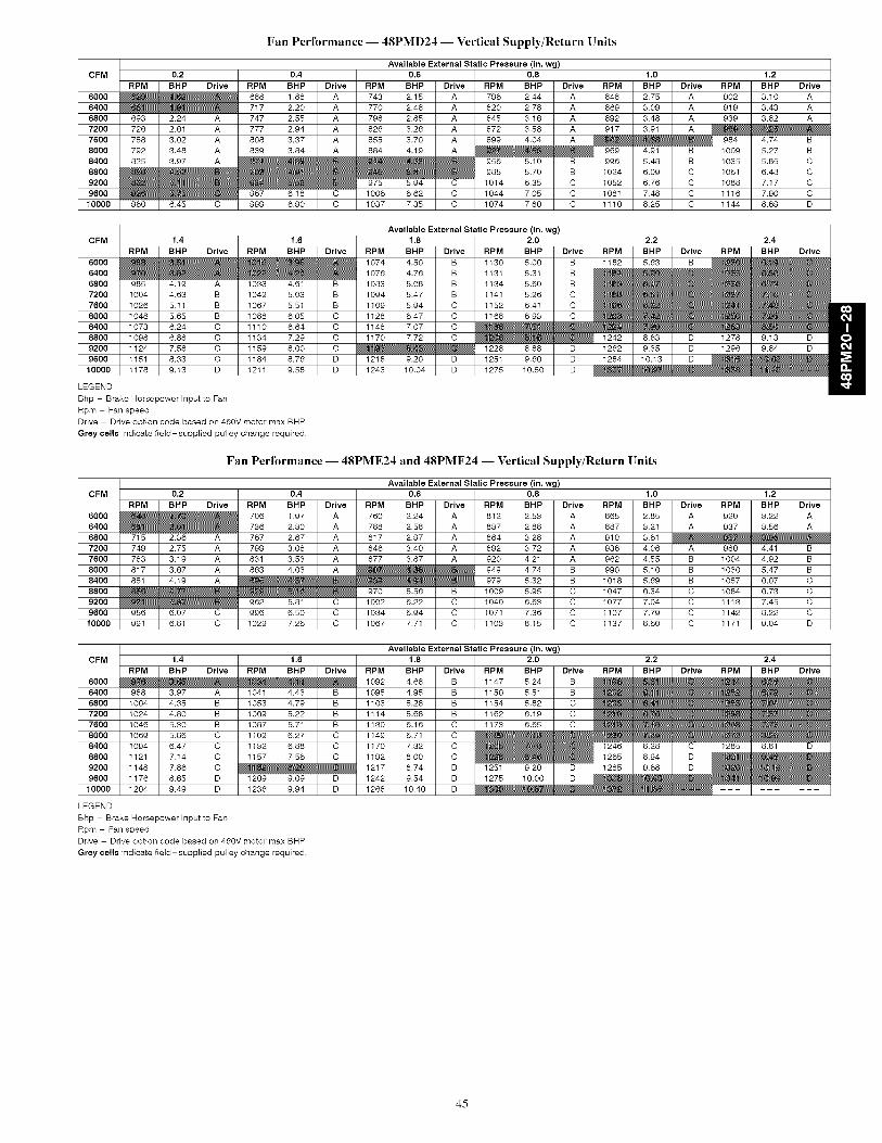
Fan Performance -- 48PMD24 -- Vertical Supply/Return Units
Available External Static Pressure (in. wg)CFM 0.2 0.4 0.6 0.8 1,0 1,2
RPM BHP Drive RPM BHP Drive RPM BHP Drive RPM BHP Drive RPM BHP Drive RPM BHP Drive
6000 _ _ _ 688 1.68 A 743 2,15 A 796 2,44 A 648 2,75 A 902 3.10 A6400 _ _ _ 717 2,20 A 770 2,48 A 620 2,78 A 669 3.09 A 919 3.43 A6800 693 224 A 747 2,55 A 798 2,85 A 645 3.16 A 692 3.48 A 939 3.82 A
7200 726 2,61 A 777 2,94 A 626 3.26 A 672 3.58 A 917 3.91 A _ _
7600 758 3.02 A 608 3.37 A 655 3.70 A 699 4.04 A _ _ _ 984 4174 B8000 792 3.48 A 639 3.84 A 684 4.19 A _ _ _ 969 4191 B 1009 5.27 B8400 625 3.97 A _ _ _ _ _ _ 956 510 B 996 5.48 B 1035 5.85 C
8800 _________ 985 5.70 B 1024 6.09 C 1061 6.48 C9200 _ _ _ _ _ _ 975 594 C 1014 6.35 C 1052 6.76 C 1088 7.17 C
9600 _ _ _ 967 6118 C 1006 6.62 C 1044 7.05 C 1081 7.48 C 1116 7.90 C10000 960 645 C 999 6.90 C 1037 7.35 C 1074 7.60 C 1110 6.25 C 1144 6.69 D
Available External Static Pressure (in. wg)CFM 1.4 1.6 1.8 2.0 2.2 / 2.4
RPM BHP Drive RPM BHP Drive RPM BHP Drive RPM BHP Drive RPM I BHP I Drive _ BHP Drive6000 ______ 1074 4.50 B 1130 5.06 B 1182 I 5.63 I B __
6400 ______ 1076 4.76 B 1131 5.31 B __6800 985 4_19 A 1033 4_61 B 1083 5.08 B 1134 5.60 B _
7200 1004 4.63 B 1049 5.03 B 1094 5.47 B 1141 5.96 C _7600 1026 5.11 B 1067 5.51 B 1109 5.94 C 1152 6.41 C _
8000 1048 5.65 B 1088 6.05 C 1128 6.47 C 1168 6.93 C _8400 1073 6.24 C 1110 6.64 C 1148 7.07 C __ __
8800 1098 6.68 C 1134 7.29 C 1170 7.72 C ___ 1242 I 663 I D I 1278 9.13 D9200 1124 7.58 C 1159 6.00 C ___ 1228 688 D I 1262 I 9.35 I D I 1296 9.84 D
9600 1151 6.33 C 1184 6.76 D 1218 920 D 1251 9.66 D I 1284 I 10,13 I D ___10000 1178 9.13 D 1211 9.58 D 1243 10.04 D 1275 10.50 D _
LEGEND
Bhp - Brake Horsepower Input to Fan
Rpm - Fan speed
Drive - Drive option code based on 460V motor max BHP
Grey cells indicate field-supplied pulley change required,
Fan Performance -- 48PME24 and 48PMF24 -- Vertical Supply/Return Units
Available External Static Pressure (in. wg)CFM 0.2 0.4 0.6 0.8 1.0 1.2
RPM BHP Drive RPM BHP Drive RPM BHP Drive RPM BHP Drive RPM BHP Drive RPM BHP Drive
6000 _ _ _ 706 1.97 A 760 2,24 A 612 2,53 A 665 2,85 A 920 3.22 A
6400 _ _ _ 736 2,30 A 788 2,58 A 637 2,88 A 687 3.21 A 937 3.56 A6800 715 236 A 767 2,67 A 617 2,97 A 664 3.28 A 910 3.61 _ _ _7200 749 2,75 A 799 3.08 A 646 3.40 A 692 3.72 A 936 4.06 A 980 4_41 B
7600 783 3.19 A 631 3.53 A 677 3.87 A 920 4.21 A 962 4.55 B 1004 4.92 B
8000 617 3.67 A 663 4.03 A _ _ _ 949 4.74 B 990 5.10 B 1030 5.47 B8400 651 4.19 A ______ 979 5.32 B 1018 5.69 B 1057 6.07 C
8800 _ _ _ _ _ _ 970 5.56 B 1009 5.95 C 1047 6.34 C 1084 6.73 C9200 _ _ _ 962 5.81 C 1002 6.22 C 1040 6.63 C 1077 7.04 C 1113 7.45 C9600 956 6.07 C 996 6.50 C 1034 6.94 C 1071 7.36 C 1107 7.79 C 1142 6.22 C
10000 991 6.61 C 1029 7.26 C 1067 7.71 C 1103 6.15 C 1137 6.60 C 1171 9.04 D
Available External Static Pressure (in. wg)CFM 1.4 1.6 1.8 2.0 2.2 2.4
60006400
68007200
76008000
84008800
9200960010000
LEGEND
Bhp - Brake Horsepower Input to Fan
Rpm - Fan speed
Drive - Drive option code based on 460V motor max BHP
Grey cells indicate field-supplied pulley change required,
45

Fan Performance -- 48PMD28 -- Vertical Supply/Return Units
Available External Static Pressure (in. wg)CFM 0.2 0.4 0.6 0.8 1,0 1,2
RPM BHP Drive RPM BHP Drive RPM BHP Drive RPM BHP Drive RPM BHP Drive RPM BHP Drive
7500 719 2,59 A 770 2,93 A 817 3,26 A 861 3,59 A 903 3,93 B 944 4,28 B8000 759 3,09 A 808 3,45 A 853 3,81 A 895 4,16 B 935 4,51 B 974 4,87 B
8500 799 3,65 A 846 4,03 A 889 4,41 B 930 4,79 B 969 5,16 B 1006 5,54 B9000 840 4,28 A 884 4,68 B 926 5,09 B 966 5,48 B 1003 5,88 C 1039 6,28 C
9500 881 4,97 B 923 5,40 B 964 5,83 C 1002 6,25 C 1038 6,67 C 1073 7,09 C10000 922 5,74 B 963 6,19 C 1001 6,64 C 1038 7,09 C 1074 7,53 C 1108 7,97 C
10500 963 6,59 C 1002 7,06 C 1040 7,54 C 1075 8,01 C 1110 8,47 C 1143 8,93 D11000 1005 7,52 C 1042 8,01 C 1078 8,51 C 1113 9,01 D 1146 9,50 D 1178 9,98 D11500 1046 8,53 C 1082 9,05 D 1117 9,57 D 1151 10,09 D 1183 10,60 D 1214 11,11 D
12000 1088 9,64 D 1123 10,18 D 1156 10,72 D 1189 11,26
CFM 1,4 1,6RPM BHP Drive RPM BHP Drive RPM
7500 984 4.65 B ___ 1067
8000 ______ 10898500 1043 5193 C 1079 6_33 C 11149000 1074 6,68 C 1109 7,09 C 1142
9500 1107 7,51 C 1140 7,93 C 117210000 1140 8,41 C 1172 8,85 D 1203
10500 1174 9,40 D 1205 9,86 D 123611000 1209 10,46 D 1239 10,95 D 1269
1150012000
Available External Static Pressure (in. wg)1,8 2,0
BHP Drive RPM BHP
5.48 B 1109 5,95
6.07 C 1128 6,536,75 C 1150 7,207,52 C 1176 7,97
8,37 C 1204 8,829,31 D 1234 9,77
10,33 D 1265 10,8011,43
2,2 2,4Drive RPM BHP Drive RPM BHP Drive
c 1162 6,46 c ___C 1167 7,02 C ___c ______C ___ 1244 893 DD 1237 929 D 1269 9,78 DD 1265 10,24 D 1295 10,73 D
D 1295 11,29
LEGEND
Bhp - Brake Horsepower Input to Fan
Rpm - Fan speed
Drive - Drive option code based on 460V motor max BHP
Grey cells indicate field-supplied pulley change required,
Fan Performance -- 48PME28 and 48PMF28 -- Vertical Supply/Return Units
Available External Static Pressure (in. wg)CFM 0.2 0.4 0.6 0.8 1.0 1.2
RPM BHP Drive RPM BHP Drive RPM BHP Drive RPM BHP Drive RPM BHP Drive RPM BHP Drive7500 743 2,75 A 792 3,09 A 838 3,42 A 881 3,75 B 922 4,09 B 963 4,45 B
8000 785 3,28 A 832 3,64 A 875 3,99 B 916 4,34 B 956 4,70 B 995 5,07 B8500 827 3,88 A 872 4,26 A 914 4,63 B 953 5,01 B 991 5,38 B 1028 5,77 C
9000 869 4,54 A 912 4,95 B 952 5,35 B 990 5,74 B 1027 6,14 C 1062 6,54 C9500 912 5,28 B 953 5,71 B 991 6,13 C 1028 6,55 C 1063 6,97 C 1098 7,39 C
10000 954 6,10 C 994 6,55 C 1031 7,00 C 1067 7,44 C 1101 7,88 C 1134 8,32 C10500 997 7,00 C 1035 7,47 C 1071 7,95 C 1105 8,41 C 1138 8,87 D 1170 9,34 D11000 1040 7,99 C 1076 8,48 C 1111 8,98 D 1144 9,47 D 1177 9,96 D 1208 10,44 D
11500 1083 9,06 D 1118 9,59 D 1152 10,10 D 1184 10,62 D 1215 11,13 D12000 1126 10,24 D 1160 10,78 D 1192 11,32
Available External Static Pressure (in, wg)
CFM 1,4 1,6 1,8 2,0 2,2 2,4
RPM BHP Drive RPM BHP Drive RPM BHP Drive RPM BHP Drive RPM BHP Drive RPM BHP Drive
7500 1003 4,83 B ______ 1129 6,19 C 1173 6,74 C ___
8000 ___ 1071 5,87 C 1109 6,31 C 1148 6,78 C ______
8500 1064 6,16 C 1100 6,58 C 1136 7,01 C 1172 7,47 C ______
9000 1097 6,95 C 1131 7,37 C 1165 7,81 C ___ 1233 8,75 D 1267 9,27 D
9500 1131 7,81 C 1163 8,25 C 1196 8,69 D 1228 9,16 D 1260 9,64 D 1292 10,15 D
10000 1166 8,76 D 1197 9,21 D 1228 9,67 D 1259 10,14 D 1289 10,63 D ___10500 1201 9,80 D 1232 10,26 D 1261 10,74 D 1291 11,22
11000 1238 10,92 D 1267 11,41
11500
12000
LEGEND
Bhp - Brake Horsepower Input to Fan
Rpm - Fan speed
Drive - Drive option code based on 460V motor max BHP
Grey cells indicate field-supplied pulley change required,
46

Fan Performance -- 48PMD20 -- Horizontal Supply/Return Units
Airflow
(Cfm)
5000
5500
6000
6500
7000
7500
8000
8500
9000
0.2
Rpm
862937
F1013
1089
G 1166
1243H
1320
1398
Bhp
2.653.26
3.58
4.48
5.52
6.71
8.07
9.60
Rpm
917F 988
1060
G 1133
1207H
1282
1356
Pressure (in. wg)0.4 0.8
Available External Static
0.6
Bhp Rpm
2.93 969F
3.56 1036
3.96 1105
4.89 G 1175
5.96 1247H
7.18 1319
8.57 1392
Bhp Rpm
3.21 1019F
3.53 10834.35 1149
G5.31 1216
6.41 H 1285
7.66 1355
9.08
Bhp
3.17
3.904.75
5.73
6.86
8.14
Rpm
F 1066
1127G
1191
1256H
1323
1391
1.0
Bhp
3.52
4.28
5.16
6.17
7.32
8.63
Airflow
(Cfm)
5000
5500
6000
6500
7000
7500
8000
8500
9000
Rpm
F 1112
1171G
1232
H 1295
1360
1.2
Bhp
3.88
4.67
5.57
6.61
7.80
Rpm
F 1156
G 1212
1271H
1333
1396
1.4
Available External Static
1.6
Bhp Rpm
4.25 1199G
5.06 1253
6.00 H 1310
7.06 1369
8.27
Pressure (in. wg)
Bhp Rpm
4.63 G 1240
5.47 H 1292
6.43 1348
7.52
1.8
Bhp
5.02
5.88
6.87
Rpm
G 1280
H 1331
1384
2.0
Bhp
5.42
6.30
7.31
LEGEND
Bhp - Brake Horsepower Input to Fan
Boldface indicates field-supplied drive required.NOTES:
1. Motor drive ranges:
(E) Low Range: Not Used(F) Mid-Low Range: 896 to 1227 rpm, 4.26 Bhp (208/230 and 460-v), 873 to 1108 rpm, 5.75 Bhp (575-v)
(G) Mid-High Range: 1113 to 1414 rpm, 5.75 Bhp(H) High Range: 1096 to 1339 rpm, 8.63 Bhp
All other rpms require field-supplied drive.2. See General Fan Performance Notes.
Fan Performance -- 48PME20 -- Horizontal Supply and Return Units
Airflow
(Cfm)
5000
5500
6000
6500
7000
7500
8000
8500
9000
0.2
Rpm
875952
F1029
1106
G 1184
H 1262
1341
Bhp Rpm
2.74 9313.38 F 1003
3.74 1077
4.67 G 1151
5.75 1226H
7.00 1302
8.41 1378
Pressure (in. wg)0.4 0.8
Available External Static
0.6
Bhp Rpm
3.04 984F
3.32 1053
4.15 1123G
5.11 1194
6.23 H 1266
7.50 1340
8.95
Bhp Rpm
3.34 1035F
3.70 11004.56 G 1167
5.56 1236H
6.71 1306
8.01 1377
Bhp
3.33
4.094.98
6.01
7.19
8.53
Rpm
F 1083
1145G
1210
H 1276
1344
1.0
Bhp
3.69
4.49
5.41
6.47
7.68
Airflow
(Cfm)
5000
5500
6000
6500
7000
7500
8000
8500
9000
Rpm
1130
1189
1.2 1.4 1.8
Bhp Rpm
4.07 1174G
4.90 1232
Available External Static
1.6
Bhp Rpm
4.45 1218G
5.31 1273
H 1331
1391
Pressure (in. wg)
Bhp Rpm
4.84 G 1259
5.72 H 1313
Bhp
5.23
6.15
Rpm
G 1300
1352
1251H
1315
1381
5.85 H
6.94
8.18
1292
1354
6.29
7.41
6.74 1369
7.89
7.19 m
m
m
m
m
m
m
2.0
Bhp
5.63
6.58
LEGEND
Bhp - Brake Horsepower Input to Fan
Boldface indicates field-supplied drive required.NOTES:
1. Motor drive ranges:(E) Low Range: Not Used
(F) Mid-Low Range: 896 to 1227 rpm, 4.26 Bhp (208/230 and 460-v), 873 to 1108 rpm, 5.75 Bhp (575-v)(G) Mid-High Range: 1113 to 1414 rpm, 5.75 Bhp
(H) High Range: 1096 to 1339 rpm, 8.63 Bhp
All other rpms require field-supplied drive.2. See General Fan Performance Notes.
47
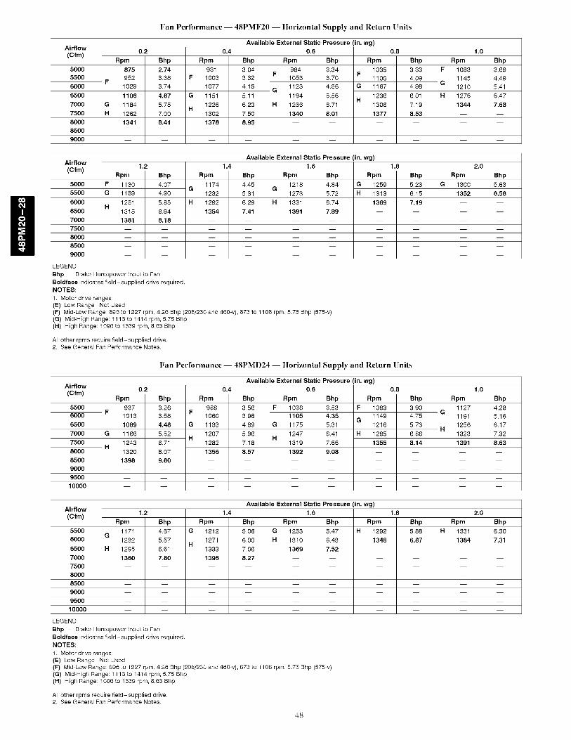
Fan Performance -- 48PMF20 -- Horizontal Supply and Return Units
Airflow
(Cfm)
5000
5500
6000
6500
7000
7500
8000
8500
9000
0.2
Rpm
875952
F1029
1106
G 1184
H 1262
1341
Bhp
2.743.38
3.74
4.67
5.75
7.00
8.41
Rpm
931F 1003
1077
G 1151
1226H
1302
1378
Available External Static Pressure (in. wg)0.4 0.6
Bhp
3.043.32
4.15
5.11
6.23
7.50
8.95
F
G
H
Rpm
9841053
1123
1194
1266
1340
Bhp
3.343.70
4.56
5.56
6.71
8.01
Rpm
1035F
1100G 1167
1236H
1306
1377m
m
m
Available External Static Pressure (in. wg)1.4 1.6
Bhp Rpm Bhp Rpm
4.45 1218 4.84 G 1259G
5.31 1273 5.72 H 1313
0.8
Bhp
3.33
4.094.98
6.01
7.19
8.53
Rpm
F 1083
1145G
1210
H 1276
1344
1.0
Bhp
3.69
4.49
5.41
6.47
7.68
Airflow
(Cfm)
5000
5500
6000
6500
7000
7500
8000
8500
9000
Rpm
1130
1189
1.2
Bhp4.07
4.90
Rpm
1174G
1232
6.29
7.41
H 1331
1391
6.74
7.89
1369
1.8
Bhp5.23
6.15
Rpm
G 1300
1352
1251H
1315
1381
5.85
6.94
8.18
H 1292
1354
7.19 m
m
m
m
m
m
m
2.0
Bhp
5.63
6.58
LEGEND
Bhp - Brake Horsepower Input to Fan
Boldface indicates field-supplied drive required.NOTES:
1. Motor drive ranges:(E) Low Range: Not Used
(F) Mid-Low Range: 896 to 1227 rpm, 4.26 Bhp (208/230 and 460-v), 873 to 1108 rpm, 5.75 Bhp (575-v)(G) Mid-High Range: 1113 to 1414 rpm, 5.75 Bhp
(H) High Range: 1096 to 1339 rpm, 8.63 Bhp
All other rpms require field-supplied drive.2. See General Fan Performance Notes.
Fan Performance -- 48PMD24 -- Horizontal Supply and Return Units
Airflow
(Cfm)
55006000
6500
7000
7500
8000
8500
9000
9500
10000
0.2
Rpm
937F
1013
1089
G 1166
1243H
1320
1398
Bhp
3.26
3.58
4.48
5.52
6.71
8.07
9.60
Rpm
988F
1060
G 1133
1207H
1282
1356
m
m
m
m
1.2 1.4
Available External Static Pressure (in. wg)
0.4 0.6
Bhp
3.56
3.96
4.89
5.96
7.18
8.57
F
G
H
Rpm
1036
1105
1175
1247
1319
1392
Bhp
3.53
4.35
5.31
6.41
7.66
9.08
Rpm
F 1083
1149G
1216
H 1285
1355
0.8
Bhp
3.90
4.75
5.73
6.86
8.14
Rpm
1127G
1191
1256H
1323
1391
1.0
Bhp
4.28
5.16
6.17
7.32
8.63
Airflow
(Cfm)
5500
6000
6500
7000
7500
8000
8500
9000
9500
10000
Rpm
1171G
1232
H 1295
1360
Bhp
4.67
5.57
Rpm
G 1212
1271H
1333
1396
Available External Static Pressure (in. wg)
1.6
Bhp Rpm Bhp Rpm
5.06 G 1253 5.47 H 1292
6.00 H 1310 6.43 1348
1369 7.52
1.8
Bhp
5.88
6.87
6.61
7.80
7.06
8.27
m m
m m
m m
m m
m m
m m
m m
m m
Rpm
H 1331
1384
LEGEND
Bhp - Brake Horsepower Input to Fan
Boldface indicates field-supplied drive required.
NOTES:
1. Motor drive ranges:(E) Low Range: Not Used
(F) Mid-Low Range: 896 to 1227 rpm, 4.26 Bhp (208/230 and 460-v), 873 to 1108 rpm, 5.75 Bhp (575-v)(G) Mid-High Range: 1113 to 1414 rpm, 5.75 Bhp
(H) High Range: 1096 to 1339 rpm, 8.63 Bhp
All other rpms require field-supplied drive.2. See General Fan Performance Notes.
2.0
Bhp
6.30
7.31
48

Airflow(Cfm)
5500
6000
6500
7000
7500
8000
8500
9000
9500
10000
Rpm
952F
1029
1106
G 1184
H 1262
1341
Fan Performance -- 48PME24 -- Horizontal Supply and Return Units
Available External Static Pressure (in. wg)0.2 0.4 0.6
Bhp
3,38
3.74
4.67
5.75
7,00
8.41
F
G
H
Rpm
1003
1077
1151
1226
1302
1378
Bhp Rpm Bhp Rpm
3,32 F 1053 3.70 F 1100
4,15 1123 4,56 G 1167G
5,11 1194 5,56 1236H
6,23 H 1266 6,71 1306
7,50 1340 8,01 1377
8.95
0,8
Bhp
4,09
4,98
6,01
7,19
8,53
Rpm
1145G
1210
H 1276
1344
Available ExternalStatic Pressure (in. wg)1.2 1.4 1.6 1.8
Bhp Rpm Bhp Rpm Bhp Rpm BhpG G
HH
1.0
Bhp
4.49
5.41
6.47
7.68
Airflow(Cfm)
5500
6000
6500
7000
7500
8000
8500
9000
9500
10000
LEGEND
4.90
5,85
6.94
8.18
Rpm
1189
1251
1315
1381
1232
1292
1354
5.31
6.29
7.41
G 1273
H 1331
1391
5.72
6.74
7.89
H 1313
1369
6.15
7.19
Rpm
1352
Bhp - Brake Horsepower Input to Fan
Boldface indicates field-supplied drive required.NOTES:
1. Motor drive ranges:(E) Low Range: Not Used(F) Mid-Low Range: 896 to 1227 rpm, 4.26 Bhp (208/230 and 460-v), 873 to 1108 rpm, 5.75 Bhp (575-v)(G) Mid-High Range: tlt3 to 1414 rpm, 5.75 Bhp(H) High Range: 1096 to 1339 rpm, 8.63 Bhp
All other rpms require field-supplied drive.2. See General Fan Performance Notes.
2.0
Bhp
6.58
Airflow(Cfm)
5500
6000
6500
7000
7500
8000
8500
9000
9500
10000
Rpm
952F
1029
1106
G 1184
H 1262
1341
Fan Performance -- 48PMF24 -- Horizontal Supply and Return Units
Available External Static Pressure (in, wg)0,2 0,4 0,6
Bhp
3,38
3.74
4.67
5.75
7.00
8.41
F
G
H
Rpm
1003
1077
1151
1226
1302
1378
Bhp Rpm Bhp Rpm
3,32 F 1053 3.70 F 1100
4,15 1123 4,56 G 1167G
5,11 1194 5,56 1236H
6,23 H 1266 6,71 1306
7,50 1340 8,01 1377
8.95
0,8
Bhp
4,09
4,98
6,01
7,19
8,53
Rpm
1145G
1210
H 1276
1344
Available ExternalStatic Pressure (in. wg)1.2 1.4 1.6 1.8
Bhp Rpm Bhp Rpm Bhp Rpm Bhp
G G
HH
1.0
Bhp
4.49
5.41
6.47
7.68
Airflow
(Cfm)
5500
6000
6500
7000
7500
8000
8500
9000
9500
10000
LEGEND
4.90
5,85
6.94
8.18
Rpm
1189
1251
1315
1381
1232
1292
1354
5,31
6,29
7.41
G 1273
H 1331
1391
5.72
6.74
7.89
H 1313
1369
6.15
7.19
Rpm
1352
Bhp - Brake Horsepower Input to Fan
Boldface indicates field-supplied drive required.NOTES:
1. Motor drive ranges:(E) Low Range: Not Used(F) Mid-Low Range: 896 to 1227 rpm, 4.26 Bhp (208/230 and 460-v), 873 to 1108 rpm, 5.75 Bhp (575-v)(G) Mid-High Range: tlt3 to 1414 rpm, 5.75 Bhp(H) High Range: 1096 to 1339 rpm, 8.63 Bhp
All other rpms require field-supplied drive.2. See General Fan Performance Notes.
2.0
Bhp
6.58
49
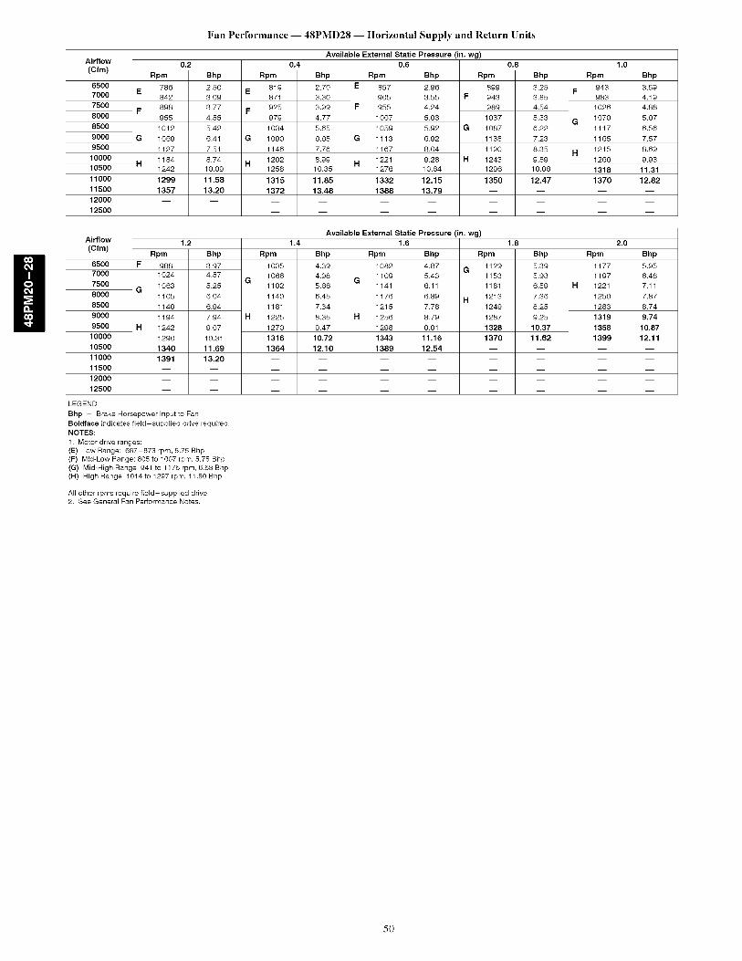
Airflow
(Cfm)
6500
7000
7500
8000
8500
9000
9500
10000
10500
11000
11500
12000
12500
Fan Performance -- 48PMD28 -- Horizontal Supply and Return Units
E
F
G
H
Rpm
786
842
898
955
Available External Static Pressure (in. wg)0.2 0.4 0.6 1.0
1012
1069
1127
1184
1242
1299
1357
Bhp
2.50
3.09
3.77
4.55
5.42
6.41
7.51
8.74
10.09
11.58
13.20
E
F
G
H
Rpm
819
871
925
979
1034
1090
1146
1202
1258
1315
1372
Bhp
2.70
3.30
3.99
4.77
5.65
6.65
7.76
8.99
10.35
11.85
13.48
E
F
G
H
Rpm
857
905
955
1007
1059
1113
1167
1221
1276
1332
1388
Bhp
2.96
3.55 F
4.24
5.03
5.92 G
6.92
8.04
9.28 H
10.64
12.15
13.79
Rpm
899
943
989
1037
1087
1138
1190
1243
1296
1350
0.8
Bhp
3.25
3.85
4.54
5.33
6.22
7.23
8.35
9.59
10.96
12.47
F
G
H
Rpm
943
983
1026
1070
1117
1165
1215
1266
1318
1370
Bhp
3.59
4.19
4.88
5.67
6.56
7.57
8.69
9.93
11.31
12.82
Airflow
(Cfm)
65007000
7500
8000
8500
9000
9500
10000
10500
11000
11500
12000
12500
Rpm
F 9881024
G 10631105
AvailableExternalStaticPressure(in. wg)1.2 1.4 1.6 1.8 2.0
1149
1194
1242
1290
1340
1391
Bhp
3.974.57
5.25
6.04
6.94
7.94
9.07
10.31
11.69
13.20
Rpm
1035
1066
1102
1140
1181
1225
1270
1316
1364
Bhp
4.39
4.98
5.66
6.45
7.34
8.35
9.47
10.72
12.10
G
Rpm
1082
1109
1141
1176
1215
1256
1298
1343
1389
Bhp
4.87 G5.43
6.11
6.89 H7.78
8.79
9.91
11.16
12.54
Rpm
1129
1153
1181
1213
1249
1287
1328
1370
Bhp
5.39
5.93
6.59
7.36
8.25
9.25
10.37
11.62
Rpm
1177
1197
H 1221
1250
1283
1319
1358
1399
Bhp
5.95
6.48
7.11
7.87
8.74
9.74
10.87
12.11
LEGEND
Bhp - Brake Horsepower Input to Fan
Boldface indicates field-supplied drive required.NOTES:
1. Motor drive ranges:(E) Low Range: 687-873 rpm, 5.75 Bhp(F) Mid-Low Range: 805 to t007 rpm, 5.75 Bhp(G) Mid-High Range: 94t to 1176 rpm, 8.63 Bhp(H) High Range: 1014 to 1297 rpm, 11.50 Bhp
All other rpms require field-supplied drive.2. See General Fan Performance Notes.
50

Fan Performance -- 48PME28 -- Horizontal Supply and Return Units
Airflow
(Cfm)
6500
7000
75008000
8500
90009500
10000
1050011000
11500
1200012500
Rpm799
E856913
F971
1029
G 108711451203
H1261
13201378
Pressure (in. wg)0.2 0.4 1.0
Bhp2.58
3.193.89
4.69
5.606.62
7.759.01
10.40
11.9313.61
E
F
G
H
Rpm883
887941
996
10521108
11651222
1279
1337
Available External Static0.6
Bhp Rpm2.79 E 872
3.41 921F
4.12 972
4.93 1024
5.85 G 10786.87 1132
8.02 1187H
9.29 1243
10.69 1299
12.23 1355
Bhp Rpm3.05 914
3.67 F 9584.39 1006
5.20 1055
6.12 G 11067.16 1158
8.31 1211H
9.59 1265
11.00 1319
12.55 1374
0.8
Bhp3.36
3.984.69
5.51
6.447.47
8.639.92
11.34
12.89
F
G
H
Rpm958
9991042
1088
11361185
12361288
1341
1394
m
m
Pressure (in. wg)0.2 0.4 0.8 1.0
Bhp3.71
4.335.04
5.86
6.787.82
8.9910.28
11.70
13.26
Airflow
(Cfm)
65007000
7500
80008500
90009500
10000
1050011000
11500
1200012500
RpmF 1005
10411080
G1122
11671214
H1262
13121363
Bhp4.124.725.43
6.24
7.168.21
9.37
10.6612.09
LEGEND
Bhp - Brake Horsepower Input to Fan
Boldface indicates field-supplied drive required.NOTES:
1. Motor drive ranges:(E) Low Range: 687-873 rpm, 5.75 Bhp(F) Mid-Low Range: 805 to t007 rpm, 5.75 Bhp(G) Mid-High Range: 94t to 1176 rpm, 8.63 Bhp(H) High Range: 1014 to 1297 rpm, 11.50 Bhp
All other rpms require field-supplied drive.2. See General Fan Performance Notes.
Rpm105210841119
1158
12001244
1290
13381387
Available External Static0.6
Bhp Rpm4.57 11005.16 G 11285.86 1160
6.66 1195
7.58 H 12348.62 1275
9.78 1319
11.08 136512.51
Bhp Rpm5.06 1148
G5.64 11726.33 1201
7.13 H 1233
8.04 12699.07 1308
10.23 1349
11.52 1392
Bhp5.606.176.84
7.63
8.539.56
10.71
12.00
Rpm11951217
H 1242
1272
13041340
1379
Bhp6.176.747.40
8.17
9.0610.08
11.23
51

Fan Performance -- 48PMF28 -- Horizontal Supply and Return Units
Airflow
(Cfm)
6500
7000
75008000
8500
90009500
10000
1050011000
11500
1200012500
Rpm799
E856913
F971
1029
G 108711451203
H1261
13201378
AvailableExternalStaticPressure(in. wg)0.2 0.4 0.6 0.8 1.0
Bhp2.58
3.193.89
4.69
5.606.62
7.759.01
10.40
11.9313.61
E
F
G
H
Rpm883
887941
996
10521108
11651222
1279
1337
Bhp2.79
3.414.12
4.93
5.856.87
8.029.29
10.69
12.23
E
F
G
H
Rpm872
921972
1024
10781132
11871243
1299
1355
Bhp Rpm3.05 914
3.67 F 9584.39 1006
5.20 1055
6.12 G 11067.16 1158
8.31 1211H
9.59 1265
11.00 1319
12.55 1374
Bhp3.36
3.984.69
5.51
6.447.47
8.639.92
11.34
12.89
F
G
H
Rpm958
9991042
1088
11361185
12361288
1341
1394
m
m
Available External Static Pressure (in. wg)0.2 0.4 0.6 0.8 1.0
Bhp3.71
4.335.04
5.86
6.787.82
8.9910.28
11.70
13.26
Airflow
(Cfm)
65007000
7500
80008500
90009500
10000
1050011000
11500
1200012500
RpmF 1005
10411080
G1122
11671214
H1262
13121363
Bhp4.124.725.43 G
6.24
7.16
8.21 H9.37
10.6612.09
Rpm105210841119
1158
12001244
1290
13381387
Bhp4.575.165.86
6.66
7.588.62
9.78
11.0812.51
G
Rpm110011281160
1195
12341275
1319
1365
Bhp Rpm5.06 1148
G5.64 11726.33 1201
7.13 H 1233
8.04 12699.07 1308
10.23 1349
11.52 1392
Bhp5.606.176.84 H
7.63
8.539.56
10.71
12.00
Rpm119512171242
1272
13041340
1379
Bhp6.176.747.40
8.17
9.0610.08
11.23
LEGEND
Bhp - Brake Horsepower Input to Fan
Boldface indicates field-supplied drive required.NOTES:
1. Motor drive ranges:(E) Low Range: 687-873 rpm, 5.75 Bhp(F) Mid-Low Range: 805 to t007 rpm, 5.75 Bhp(G) Mid-High Range: 94t to 1176 rpm, 8.63 Bhp(H) High Range: 1014 to 1297 rpm, 11.50 Bhp
All other rpms require field-supplied drive.2. See General Fan Performance Notes.
1. Static pressure losses (i.e., economizer, electric heat, etc.) must be
added to external static pressure before entering Fan Performancetable.
2. Interpolation is permissible. Do not extrapolate.
3. Fan performance is based on wet coils, clean filters, and casing
losses. See Accessory/FIOP Static Pressure information.
4. Extensive motor and drive testing on these units ensures that the
full horsepower range of the motor can be utilized with
confidence. Using the fan motors up to the bhp rating shown will
not result in nuisance tripping or premature motor failure. Unit
warranty will not be affected.
GENERAL NOTES FOR FAN PERFORMANCE DATA TABLES
5. Use of a field-supplied motor may affect wire size. Recalculate the
unit power supply MCA and MOCP if required. Contact the local
Carrier representative for details.
6. Use the following formula to calculate Input Watts:
Input Watts = Bhp x (746/motor eft.)
52

APPENDIX B
ADDITIONAL START-UP DATA
Operation Air Quantity Limits
48PM
20
24
28
COOLING
Minimum Cfm
5400
6000
7500
Maximum Cfm
9,000
10,000
12,000
GAS HEAT
High Heat (8 Cell)Medium Heat (8 Cell)
Low Heat (5 Cell)High Heat (8 Cell)
Medium Heat (8 Cell)Low Heat (5 Cell)High Heat (8 Cell)
Medium Heat (8 Cell)Low Heat (5 Cell)
HEATING
(NAT. GAS,
VERTICAL)
Minimum Cfm
5522
49774218
5522
49774218
5522
49774218
HEATING
(NAT. GAS,
HORIZONTAL)
Minimum Cfm
5522
49774218
5522
49774218
5470*4977*
4218
HEATING
(PROPANE,
VERTICAL)
Minimum Cfm
5522
44804218
5522
44804218
5522
44804218
HEATING
(PROPANE,
HORIZONTAL)
Minimum Cfm
4920
44803796
4920
44803796
4920*4480*
3796
*7000 cfm minimum recommended above 1.0-in. wg external static pressure.
Evaporator Fan Motor Specifications
UNIT48PM VOLTAGE EFFICIENCY % MAX BHPDRIVE
Low
Mid-Low
Mid-High
High
Low
Mid-Low
Mid-High
High
20
ORIENTATION
Vertical
Vertical
Vertical
Vertical
Horizontal
Horizontal
Horizontal
Horizontal
2O823O
46O
5752O8
23O
46O575
2O8
23O46O
575
2O823O
460575
208
230460
575
208230
460
575208
230460
575
208230
460
575
85.885.8
85.8
87.587.5
87.5
87.587.5
88.5
88.588.5
88.5
89.589.5
89.589.5
N/AN/A
N/AN/A
85.885.8
85.8
87.587.5
87.587.5
87.5
88.588.5
88.5
88.5
4.264.26
4.26
5.755.37
5.75
5.755.75
7.66
8.518.63
8.63
9.9410.45
11.1911.50
N/AN/A
N/AN/A
4.264.26
4.26
5.755.37
5.755.75
5.75
7.668.51
8.63
8.63
MAX AMPS
10.69.6
4.8
6.015.8
15.4
7.76.0
22.0
22.011.6
9.4
28.028.0
15.012.0
N/AN/A
N/AN/A
10.69.6
4.8
6.015.8
15.47.7
6.0
22.022.0
11.6
9.4
53

Table 7 - Evaporator Fan Motor Specifications (cont)
UNIT48PM VOLTAGE EFFICIENCY % MAX BHP
24
28
DRIVE
Low
Mid-Low
Mid-High
High
Low
Mid-Low
Mid-High
High
Low
Mid-Low
Mid-High
High
Low
Mid-Low
Mid-High
High
ORIENTATION
Vertical
Vertical
Vertical
Vertical
Horizontal
Horizontal
Horizontal
Horizontal
Vertical
Vertical
Vertical
Vertical
Horizontal
Horizontal
Horizontal
Horizontal
NOTES:
2O823O
46O
5752O8
23O46O
575
2O823O
46O
5752O8
23O
460575
208230
460
575208
230
460575
208
230460
575
208230
460575208
230460
575
208230
460
575208
230
460575
208230
460
575208
230
460575
208
230460
575208
230
460575
208
230460
575
85.885.8
85.8
87.587.5
87.587.5
87.5
88.588.5
88.5
88.589.5
89.5
89.589.5
N/A
N/A
N/AN/A85.8
85.8
85.887.5
87.5
87.587.5
87.5
88.588.5
88.588.587.5
87.587.5
87.5
87.587.5
87.5
87.588.5
88.5
88.588.5
89.589.5
89.5
89.587.5
87.5
87.587.5
87.5
87.587.5
87.588.5
88.5
88.588.5
89.5
89.589.5
89.5
4.264.26
4.26
5.755.37
5.755.75
5.75
7.668.51
8.63
8.639.94
10.45
11.1911.50
N/A
N/A
N/AN/A
4.26
4.26
4.265.75
5.37
5.755.75
5.75
7.668.51
8.638.635.37
5.755.75
5.75
5.375.75
5.75
5.757.66
8.51
8.638.63
9.9410.45
11.19
11.505.37
5.75
5.755.75
5.37
5.755.75
5.757.66
8.51
8.638.63
9.94
10.4511.19
11.50
MAX AMPS
10.69.6
4.8
6.015.8
15.47.7
6.0
22.022.0
11.6
9.428.0
28.0
15.012.0
N/A
N/A
N/AN/A10.6
9.6
4.86.0
15.8
15.47.7
6.0
22.022.0
11.69.4
15.8
15.47.7
6.0
15.815.4
7.7
6.022.0
22.0
11.69.4
28.028.0
15.0
12.015.8
15.4
7.76.0
15.8
15.47.7
6.022.0
22.0
11.69.4
28.0
28.015.0
12.0
1. Extensive motor and electrical testing ensures that the motors can be utilized with confidence up to the maximum applied bhp, watts, and amps. Using the fanmotor up to the maximum ratings shown will not result in nuisance tripping or premature motor failure. Unit warranty will not be affected.
2. All Indoor-fan motors 5 hp and larger meet the minimum efficiency requirements as established by the Energy Policy Act of 1992 (EPACT) effective October24, 1997.
54

Accessory/FlOP Static Pressure (in. wg)* -- 48PM20-28
COMPONENT CFM4,000 4,500 5,000 5,500 8,000 6,500 7,000 7,500 8,000
Economizer 0.02 0.03 0.04 0.05 0.06 0.07 0.08 0.09 0.10
CFM
COMPONENT 8,500 9,000 9,500 10,000 10,500 11,000 11,500 12,000Economizer 0.11 0.12 0.13 0.15 0.16 0.17 0.19 0.20
LEGEND
FlOP - Factory-Installed Option
*The static pressure must be added to the external static pressure. The sum and the evaporator entering-air cfm should thenbe used in conjunction with the Fan Performance tables to determine blower rpm and watts.
Fan Rpm at Motor Pulley Settings*
UNIT48PM
20 and 24(230 and 480 volt)
20 and 24(575 volt)
28(all voltages)
MOTOR PULLEY TURNS OPENDRIVE
0 1/2 1 11/2 2 21/2 3 31/2 4 41/2 5 51/2 8
Low 685 706 727 749 770 791 812 833 854 876 897 918 939
Mid-Low 949 970 992 1013 1035 1056 1078 1099 1120 1142 1163 1185 1206
Mid-High 941 961 980 1000 1019 1039 1059 1078 1098 1117 1137 1156 1176
High 1014 1038 1061 1085 1108 1132 1156 1179 1203 1226 1250 1273 1297Low n/a n/a n/a n/a n/a n/a n/a n/a n/a n/a n/a n/a n/a
Mid-Low 896 924 951 979 1006 1034 1062 1089 1117 1144 1172 1199 1227
Mid-High 1113 1138 1163 1188 1213 1238 1264 1289 1314 1339 1364 1389 1414High 1096 1116 1137 1157 1177 1197 1218 1238 1258 1278 1299 1319 1339Low 751 768 785 802 819 836 853 869 886 903 920 937 954
Mid-Low 949 970 992 1013 1035 1056 1078 1099 1120 1142 1163 1185 1206
Mid-High 941 961 980 1000 1019 1039 1059 1078 1098 1117 1137 1156 1176
High 1014 1038 1061 1085 1108 1132 1156 1179 1203 1226 1250 1273 1297Low n/a n/a n/a n/a n/a n/a n/a n/a n/a n/a n/a n/a n/a
Mid-Low 873 893 912 932 951 971 991 1010 1030 1049 1069 1088 1108
Mid-High 1113 1138 1163 1188 1213 1238 1264 1289 1314 1339 1364 1389 1414High 1096 1116 1137 1157 1177 1197 1218 1238 1258 1278 1299 1319 1339Low 687 703 718 734 749 765 780 796 811 827 842 858 873
Mid-Low 805 822 839 856 872 889 906 923 940 957 973 990 1007
Mid-High 941 961 980 1000 1019 1039 1059 1078 1098 1117 1137 1156 1176
High 1014 1038 1061 1085 1108 1132 1156 1179 1203 1226 1250 1273 1297Low 687 703 718 734 749 765 780 796 811 827 842 858 873
Mid-Low 805 822 839 856 872 889 906 923 940 957 973 990 1007
Mid-High 941 961 980 1000 1019 1039 1059 1078 1098 1117 1137 1156 1176Hi qh 1014 1038 1061 1085 1108 1132 1156 1179 1203 1226 1250 1273 1297
LEGEND
n/a - not available
*Approximate fan rpm shown,NOTE: Factory pulley speed setting is at 3 turns open.
55

UNIT START-UP CHECKLIST
MODEL NO.: SERIAL NO:
DATE: TECHNICIAN:
I. PRE-START-UP:
[] VERIFY THAT ALL PACKING MATERIALS HAVE BEEN REMOVED FROM UNIT
[] VERIFY INSTALLATION OF OUTDOOR AIR HOOD
[] VERIFY INSTALLATION OF FLUE EXHAUST AND INLET HOOD
[] VERIFY THAT CONDENSATE CONNECTION IS INSTALLED PER INSTRUCTIONS
[] VERIFY THAT ALL ELECTRICAL CONNECTIONS AND TERMINALS ARE TIGHT
[] VERIFY GAS PRESSURE TO UNIT GAS VALVE IS WITHIN SPECIFIED RANGE
[] CHECK GAS PIPING FOR LEAKS
[] CHECK THAT INDOOR-AIR FILTERS ARE CLEAN AND IN PLACE
[] CHECK THAT OUTDOOR AIR INLET SCREENS ARE IN PLACE
H [] VERIFY THAT UNIT IS LEVEL
[] CHECK FAN WHEEL AND PROPELLER FOR LOCATION IN HOUSING/ORIFICE AND VERIFY SETSCREW IS TIGHT
[] VERIFY THAT FAN SHEAVES ARE ALIGNED AND BELTS ARE PROPERLY TENSIONED
[] VERIFY THAT SCROLL COMPRESSORS ARE ROTATING IN THE CORRECT DIRECTION
[] VERIFY INSTALLATION OF THERMOSTAT
[] VERIFY THAT CRANKCASE HEATERS HAVE BEEN ENERGIZED FOR AT LEAST 24 HOURS
II. START-UP
ELECTRICAL
SUPPLY VOLTAGE L1-L2 L2-L3 L3-L1
COMPRESSOR AMPS--COMPRESSOR A1
--COMPRESSOR B1
SUPPLY FAN AMPS
TEMPERATURES
OUTDOOR-AIR TEMPERATURE
RETURN-AIR TEMPERATURE
COOLING SUPPLY AIR
GAS HEAT SUPPLY AIR
PRESSURES
GAS INLET PRESSURE IN.WG
GAS MANIFOLD PRESSURE STAGE NO. 1 IN.WG
REFRIGERANT SUCTION CIRCUIT A PSlG
CIRCUIT B (12) PSlG
PSlG
REFRIGERANT DISCHARGE CIRCUIT A PSlG
CIRCUIT B (12) PSlG
VERIFY REFRIGERANT CHARGE USING CHARGING CHARTS[]
L1 L2 L3
L1 L2 L3
L1 L2 L3
F DB (Dry Bulb)
F DB
F
GENERAL
[]
F WB (Wet Bulb)
ECONOMIZER MINIMUM VENT AND CHANGEOVER SETTINGS TO JOB REQUIREMENTS
Copyright 2008 Carrier Corp, • 7310 W, Morris St. • Indianapolis, IN 46231 Printed in U,S,A, Edition Date: 3/08
Manufacturer reserves the right to change, at any time, specification8 and design8 without notice and without obligations,
Catalog No:48PM- 1SI
Replaces: NEW
56