Embed Size (px)
Citation preview
Installation InstructionsBMW M3 E46
355mm RearBig Brake Upgrade
ST-40 Caliper
98-137-1471 Rev 03 10-17-07
2
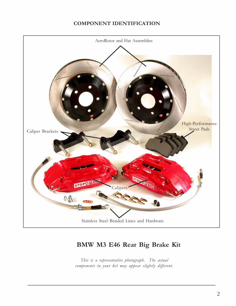
COMPONENT IDENTIFICATION
BMW M3 E46 Rear Big Brake Kit
This is a representative photograph. The actualcomponents in your kit may appear slightly different.
AeroRotor and Hat Assemblies
Caliper Brackets
High-PerformanceStreet Pads
Calipers
Stainless Steel Braided Lines and Hardware
3
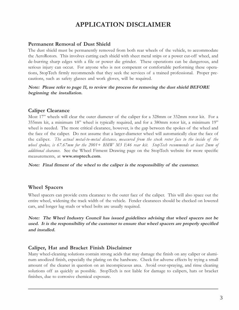
APPLICATION DISCLAIMER
Note: Final fitment of the wheel to the caliper is the responsibility of the customer.
Permanent Removal of Dust ShieldThe dust shield must be permanently removed from both rear wheels of the vehicle, to accommodatethe AeroRotors. This involves cutting each shield with sheet metal snips or a power cut-off wheel, andde-burring sharp edges with a file or power die grinder. These operations can be dangerous, andserious injury can occur. For anyone who is not competent or comfortable performing these opera-tions, StopTech firmly recommends that they seek the services of a trained professional. Proper pre-cautions, such as safety glasses and work gloves, will be required.
Caliper ClearanceMost 17” wheels will clear the outer diameter of the caliper for a 328mm or 332mm rotor kit. For a355mm kit, a minimum 18” wheel is typically required, and for a 380mm rotor kit, a minimum 19”wheel is needed. The more critical clearance, however, is the gap between the spokes of the wheel andthe face of the caliper. Do not assume that a larger-diameter wheel will automatically clear the face ofthe caliper. The actual metal-to-metal distance, measured from the stock rotor face to the inside of thewheel spokes, is 67.67mm for the 2001+ BMW M3 E46 rear kit. StopTech recommends at least 2mm ofadditional clearance. See the Wheel Fitment Drawing page on the StopTech website for more specificmeasurements, at www.stoptech.com.
Note: Please refer to page 11, to review the process for removing the dust shield BEFOREbeginning the installation.
Wheel SpacersWheel spacers can provide extra clearance to the outer face of the caliper. This will also space out theentire wheel, widening the track width of the vehicle. Fender clearances should be checked on loweredcars, and longer lug studs or wheel bolts are usually required.
Note: The Wheel Industry Council has issued guidelines advising that wheel spacers not beused. It is the responsibility of the customer to ensure that wheel spacers are properly specifiedand installed.
Caliper, Hat and Bracket Finish DisclaimerMany wheel-cleaning solutions contain strong acids that may damage the finish on any caliper or alumi-num anodized finish, especially the plating on the hardware. Check for adverse effects by trying a smallamount of the cleaner in question on an inconspicuous area. Avoid over-spraying, and rinse cleaningsolutions off as quickly as possible. StopTech is not liable for damage to calipers, hats or bracketfinishes, due to corrosive chemical exposure.
4
APPLICATION DISCLAIMER (Cont’d.)
StopTech, SportStop, Balanced Brake Upgrades and AeroRotor are trademarks of StopTech.All other company or brand names mentioned or shown in this manual are trademarks of theirrespective companies.
Brake Vibration - THIS IS IMPORTANT!The most common cause of brake vibration is improper bed-in of pads and rotors, or improper padselection for the specific driving environment. Rotor run-out may also cause vibration, but precisionmanufacturing and inspection typically mean that run-out is not an issue. Modern production methodsensure that the rotor run-out is within +/- 0.002” when installed on a StopTech aluminum hat, and itcontrols thickness variation to within 0.0003”. Under the most extreme conditions, any rotor may warp,but uneven pad deposition is a more typical cause of vibration. If the system is not properly bedded-in,or if street pads are run on an open track, uneven pad deposits will occur, causing an ever-worseningvibration. Failure to immediately address a pad deposition/vibration issue may lead to permanent dam-age of the rotors. Please read and understand the bed-in procedure included in this manual.
Note: StopTech is not liable for vibrations caused by extreme usage or improper bed-in of padsand rotors.
Note: The customer is responsible for any squeal-related problems due to pad selection.
Brake NoiseCertain brake pad compounds make more noise than others. Proper anti-squeal shim plates between thecaliper pistons and backing plate of the pad help to reduce the problem. Anti-squeal lubricants are alsoavailable, to reduce some of the noise. The reality is that performance pads are more prone to brakesqueal.
5
Important Notices
Cleaning of RotorsThe AeroRotors supplied with this kit are coated with a water-soluble, environmentally friendly rustinhibitor. This coating MUST BE WASHED OFF WITH SOAP AND WATER before installation.Brake cleaner is not as effective as soap and water. Even if it doesn’t look as if anything is coming offthe rotor, the rust inhibitor is there, and must be entirely cleaned. Rotors will quickly rust withoutprotection, so if the rotor is not rusty, it’s still coated. After cleaning, you may see the rotor start todevelop a slight rust color. This is normal, and indicates that all of the rust inhibitor has been removed.
Rotor and Pad Bed-inProper rotor and pad bed-in is essential to the performance of your new brake system. Failure to prop-erly bed-in the brakes will seriously impact how well they work, and how long they will last. The numberone cause of brake vibration is uneven pad material deposition on the rotor. Proper bed-in will greatlyminimize such problems. Follow, as closely as possible, the bed-in procedure detailed later in this manual,or refer to the StopTech website at www.stoptech.com for further information.
Wheel FitmentDo not assume that your wheels will fit. An outline drawing of your StopTech Big Brake kit is avail-able on our website at www.stoptech.com. Measure the distance from the outer face of your stockcaliper to the inner face of your wheel spokes, or make a template according to the instructions on thewebsite, to determine if a wheel spacer is necessary. DO THIS BEFORE YOU INSTALL YOURKIT!
Safety NoticeImproper handling of a vehicle, especially while raised and supported by jack stands, ramps or othermechanical means, can cause serious bodily injury or even death. It is strongly recommended that atrained, experienced mechanic, with proper equipment, install the Big Brake Kit supplied by StopTech.StopTech assumes no liability, expressed or implied, for the improper installation or use of this productor its components.
6
Disclaimer of Warranty / Limitation of LiabilityBy purchasing the STOPTECH brake components described herein and opening the accompanyingbox or packaging, the purchaser(s), buyer(s) and /or the ultimate user(s) expressly (1) acknowledgethat they have read and understand all terms set forth herein; (2) understand and agree that theSTOPTECH brake kit and/or components, whether acquired new or used, whether complete orincomplete, whether of merchantable or non-merchantable quality, whether saleable or non-saleable,is taken, purchased, selected and/or acquired “AS IS” and “WITH ALL FAULTS”; (3) acknowledgethat the brake kit and/or components contained herein are intended only for off-street use, regardlessof whether said brake kit and/or components are approved by a state or the United States Departmentof Transportation; (4) understand and agree that they bear all risks, including but not limited to therisk as to quality and performance of said brake kit and/or components, and the risk of bearing thecosts of repair or replacement of the subject brake kit and/or components, whether in defective ornon-defective condition. STOPTECH is not responsible for damage, consequential or otherwise, forequipment failure or mal-performance after installation: understand that (5) Auto Racing is adangerous sport, and products are subject to failure when exposed to the high stresses involved withuse on a racetrack.
STOPTECH MAKES NO EXPRESS OR IMPLIED WARRANTIES, WHETHER ORALOR WRITTEN, WHETHER TRUE OR UNTRUE AND REGARDLESS OF SOURCE, TO ANYPURCHASER(S), BUYER(S) OF ITS BRAKE KITS AND COMPONENTS. ANY IMPLIEDWARRANTY OF MERCHANTABILITY OR WARRANTY OF FITNESS FOR A PARTICULARPURPOSE IS HEREBY EXPRESSLY AND EFFECTIVELY DISCLAIMED AND SUCHDISCLAIMER IS ALSO HEREBY ACKNOWLEDGED BY THE PURCHASER(S), BUYER(S)AND/OR ULTIMATE USER(S). RATHER, THE PURCHASER(S), BUYER(S) AND/ORULTIMATE USER(S) EXPRESSLY AND IMPLIEDLY AFFIRM THAT HE/SHE/THEY ARERELYING UPON THEIR OWN SKILL AND JUDGMENT IN SELECTING AND PURCHASINGTHE KIT AND/OR COMPONENTS CONTAINED HEREIN AS SUITABLE FOR THEIRINTENDED USE. The purchaser(s), buyer(s) and/or the ultimate user(s) understand and agree thatno officer, director, employee, agent salesman, representative, distributor, or other affiliate ofSTOPTECH has any authority to make nay statement or representation contrary to the terms set forthhereinabove. Any such statement or representation is hereby effectively disavowed.
Important Notices (Cont’d.)
7
BMW M3 E46 Rear Axle KitNote: It is important to read and understand this ENTIRE installation manual, including thebreak-in procedures, before starting the installation.
Kit ContentsYour StopTech Big Brake kit includes the following:1 pair of ST-40 four-piston calipers, sized specifically for your vehicle1 set of high-performance street pads (not suitable for track use)1 pair of 355 X 32mm two-piece rotor assemblies1 pair of aluminum caliper adapter brackets4 ea. 7/16-20 self-locking jet nuts4 ea. 12mm washers1 pair of stainless steel brake lines1 pair of line locators2 ea. banjo bolts4 ea. copper crush washers2 ea. rubber end caps
Tools and Equipment RequiredSome different models or years of vehicle may use different sized fasteners. Every effort has been takento correctly identify the proper sized tool for each job. Occasionally, the manufacturer may use analternate fastener. Check that each tool correctly fits the fastener before loosening or tightening it.The following tools and equipment will be needed:16mm wrench or socket (1/2” drive suggested)14mm wrench or socket (in some cases, 9/16” may be required)10mm wrench or socket11mm flare wrench11mm box wrench1/2” wrench or socket (3/8” drive suggested)6mm Aleen (hex) wrench6mm Allen (hex) wrenchTorque wrenches capable of 10-85 lb-ft settingsSheet metal snips or cut-off wheel, and a file or die grinderStandard and needle-nose pliersFlat-head screwdriverSafety glasses and work gloves for the metal-cutting processSmall drip tray or several ragsSmall funnel or suitable means of filling master cylinder reservoirAnti-seize compoundBrake bleed bottle1 pair of jack stands, ramps or other means of supporting vehiclePlastic or non-marring malletDOT 3 or 4 Brake Fluid. Check manufacturer’s recommendation for compatibility. StopTech recom-mends flushing brake fluid every 1-2 years, or more often under severe usage conditions. If not donerecently, the installation of a brake kit is an excellent opportunity to refresh your brake fluid, or toupgrade to a higher-performance fluid, such as Motul 600.
8
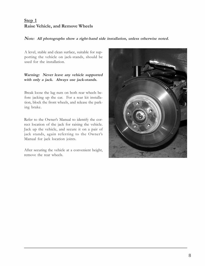
Warning: Never leave any vehicle supportedwith only a jack. Always use jack-stands.
A level, stable and clean surface, suitable for sup-porting the vehicle on jack-stands, should beused for the installation.
Step 1Raise Vehicle, and Remove Wheels
Refer to the Owner’s Manual to identify the cor-rect location of the jack for raising the vehicle.Jack up the vehicle, and secure it on a pair ofjack stands, again referring to the Owner’sManual for jack location joints.
Note: All photographs show a right-hand side installation, unless otherwise noted.
Break loose the lug nuts on both rear wheels be-fore jacking up the car. For a rear kit installa-tion, block the front wheels, and release the park-ing brake.
After securing the vehicle at a convenient height,remove the rear wheels.
9
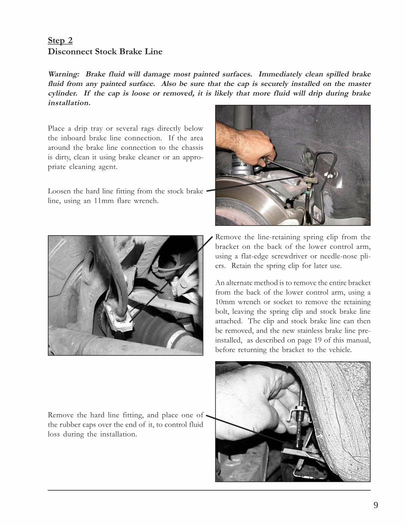
Step 2Disconnect Stock Brake Line
Loosen the hard line fitting from the stock brakeline, using an 11mm flare wrench.
Place a drip tray or several rags directly belowthe inboard brake line connection. If the areaaround the brake line connection to the chassisis dirty, clean it using brake cleaner or an appro-priate cleaning agent.
Remove the hard line fitting, and place one ofthe rubber caps over the end of it, to control fluidloss during the installation.
Warning: Brake fluid will damage most painted surfaces. Immediately clean spilled brakefluid from any painted surface. Also be sure that the cap is securely installed on the mastercylinder. If the cap is loose or removed, it is likely that more fluid will drip during brakeinstallation.
Remove the line-retaining spring clip from thebracket on the back of the lower control arm,using a flat-edge screwdriver or needle-nose pli-ers. Retain the spring clip for later use.
An alternate method is to remove the entire bracketfrom the back of the lower control arm, using a10mm wrench or socket to remove the retainingbolt, leaving the spring clip and stock brake lineattached. The clip and stock brake line can thenbe removed, and the new stainless brake line pre-installed, as described on page 19 of this manual,before returning the bracket to the vehicle.
10
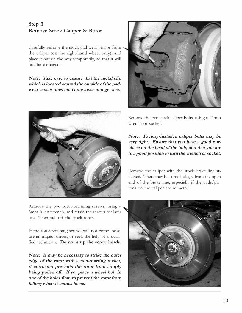
Step 3Remove Stock Caliper & Rotor
Remove the caliper with the stock brake line at-tached. There may be some leakage from the openend of the brake line, especially if the pads/pis-tons on the caliper are retracted.
Note: Factory-installed caliper bolts may bevery tight. Ensure that you have a good pur-chase on the head of the bolt, and that you arein a good position to turn the wrench or socket.
Remove the two stock caliper bolts, using a 16mmwrench or socket.
Remove the two rotor-retaining screws, using a6mm Allen wrench, and retain the screws for lateruse. Then pull off the stock rotor.
Note: It may be necessary to strike the outeredge of the rotor with a non-marring mallet,if corrosion prevents the rotor from simplybeing pulled off. If so, place a wheel bolt inone of the holes first, to prevent the rotor fromfalling when it comes loose.
If the rotor-retaining screws will not come loose,use an impact driver, or seek the help of a quali-fied technician. Do not strip the screw heads.
Carefully remove the stock pad-wear sensor fromthe caliper (on the right-hand wheel only), andplace it out of the way temporarily, so that it willnot be damaged.
Note: Take care to ensure that the metal clipwhich is located around the outside of the pad-wear sensor does not come loose and get lost.
11
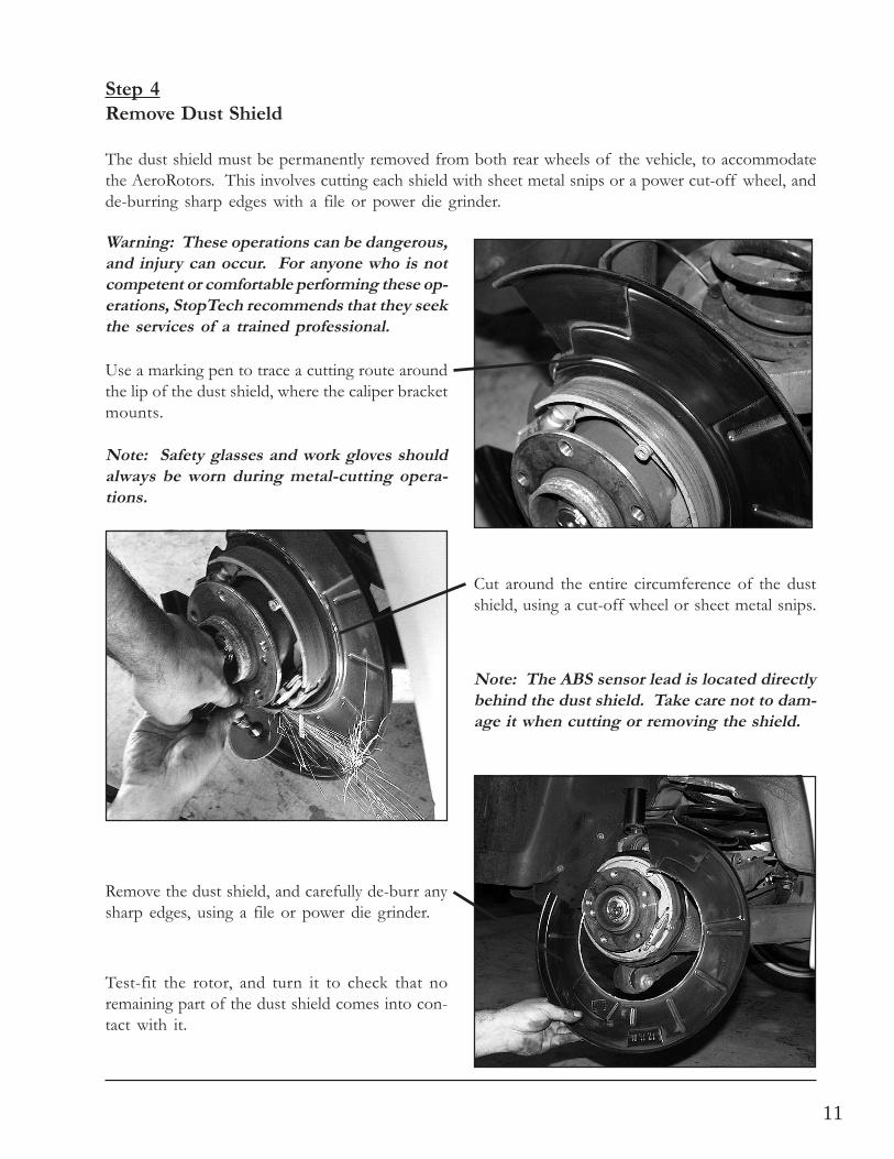
Use a marking pen to trace a cutting route aroundthe lip of the dust shield, where the caliper bracketmounts.
Step 4Remove Dust Shield
The dust shield must be permanently removed from both rear wheels of the vehicle, to accommodatethe AeroRotors. This involves cutting each shield with sheet metal snips or a power cut-off wheel, andde-burring sharp edges with a file or power die grinder.
Warning: These operations can be dangerous,and injury can occur. For anyone who is notcompetent or comfortable performing these op-erations, StopTech recommends that they seekthe services of a trained professional.
Cut around the entire circumference of the dustshield, using a cut-off wheel or sheet metal snips.
Remove the dust shield, and carefully de-burr anysharp edges, using a file or power die grinder.
Test-fit the rotor, and turn it to check that noremaining part of the dust shield comes into con-tact with it.
Note: The ABS sensor lead is located directlybehind the dust shield. Take care not to dam-age it when cutting or removing the shield.
Note: Safety glasses and work gloves shouldalways be worn during metal-cutting opera-tions.
12
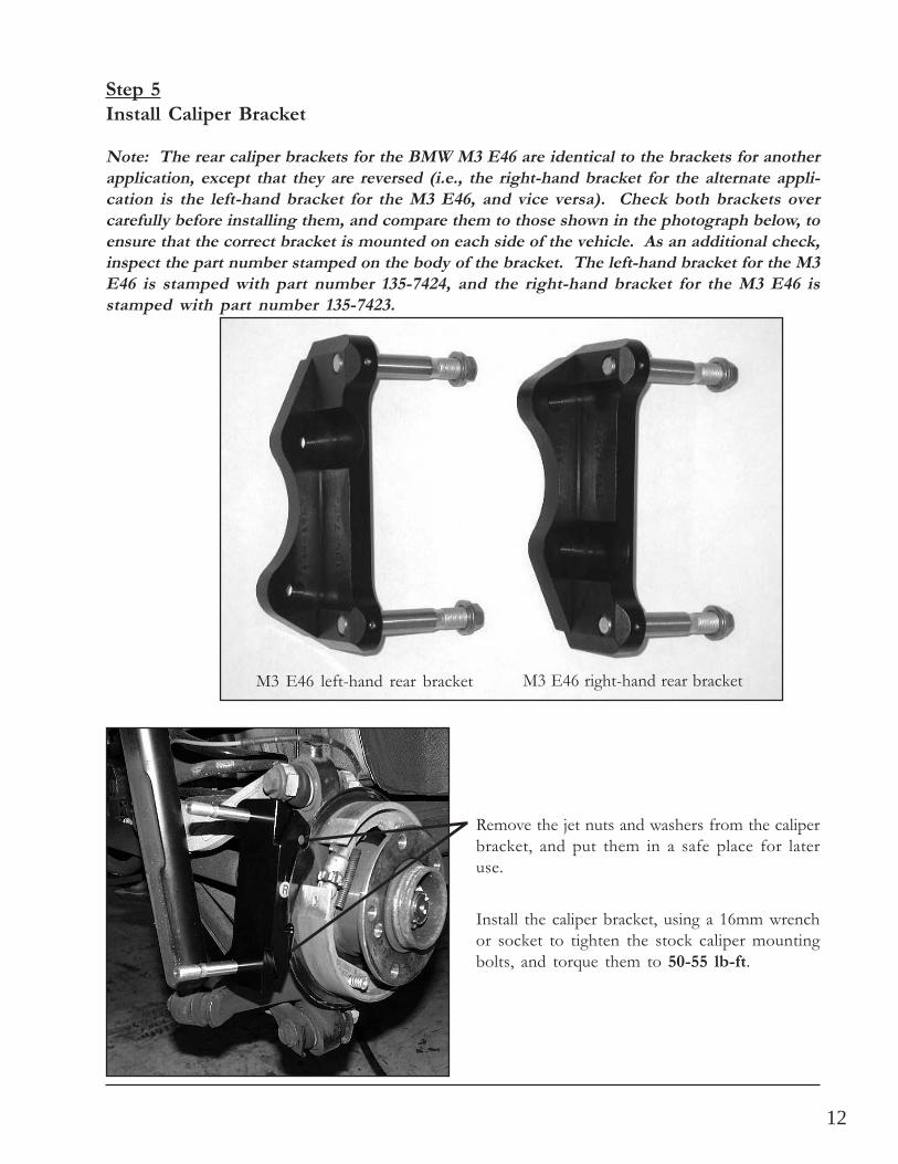
Step 5Install Caliper Bracket
Install the caliper bracket, using a 16mm wrenchor socket to tighten the stock caliper mountingbolts, and torque them to 50-55 lb-ft.
Remove the jet nuts and washers from the caliperbracket, and put them in a safe place for lateruse.
Note: The rear caliper brackets for the BMW M3 E46 are identical to the brackets for anotherapplication, except that they are reversed (i.e., the right-hand bracket for the alternate appli-cation is the left-hand bracket for the M3 E46, and vice versa). Check both brackets overcarefully before installing them, and compare them to those shown in the photograph below, toensure that the correct bracket is mounted on each side of the vehicle. As an additional check,inspect the part number stamped on the body of the bracket. The left-hand bracket for the M3E46 is stamped with part number 135-7424, and the right-hand bracket for the M3 E46 isstamped with part number 135-7423.
M3 E46 left-hand rear bracket M3 E46 right-hand rear bracket
13
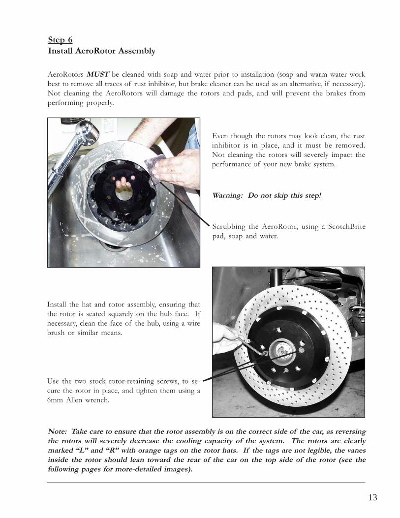
Install the hat and rotor assembly, ensuring thatthe rotor is seated squarely on the hub face. Ifnecessary, clean the face of the hub, using a wirebrush or similar means.
Step 6Install AeroRotor Assembly
AeroRotors MUST be cleaned with soap and water prior to installation (soap and warm water workbest to remove all traces of rust inhibitor, but brake cleaner can be used as an alternative, if necessary).Not cleaning the AeroRotors will damage the rotors and pads, and will prevent the brakes fromperforming properly.
Scrubbing the AeroRotor, using a ScotchBritepad, soap and water.
Warning: Do not skip this step!
Even though the rotors may look clean, the rustinhibitor is in place, and it must be removed.Not cleaning the rotors will severely impact theperformance of your new brake system.
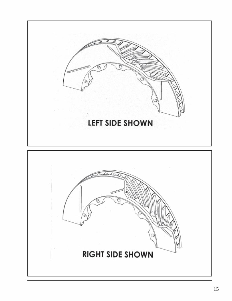
Note: Take care to ensure that the rotor assembly is on the correct side of the car, as reversingthe rotors will severely decrease the cooling capacity of the system. The rotors are clearlymarked “L” and “R” with orange tags on the rotor hats. If the tags are not legible, the vanesinside the rotor should lean toward the rear of the car on the top side of the rotor (see thefollowing pages for more-detailed images).
Use the two stock rotor-retaining screws, to se-cure the rotor in place, and tighten them using a6mm Allen wrench.
14
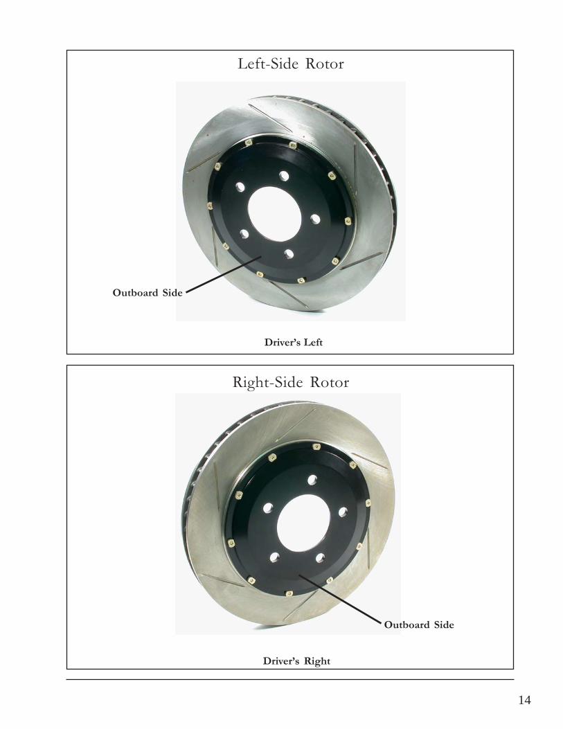
Left-Side Rotor
Right-Side Rotor
Driver’s Left
Outboard Side
Driver’s Right
Outboard Side
15
16
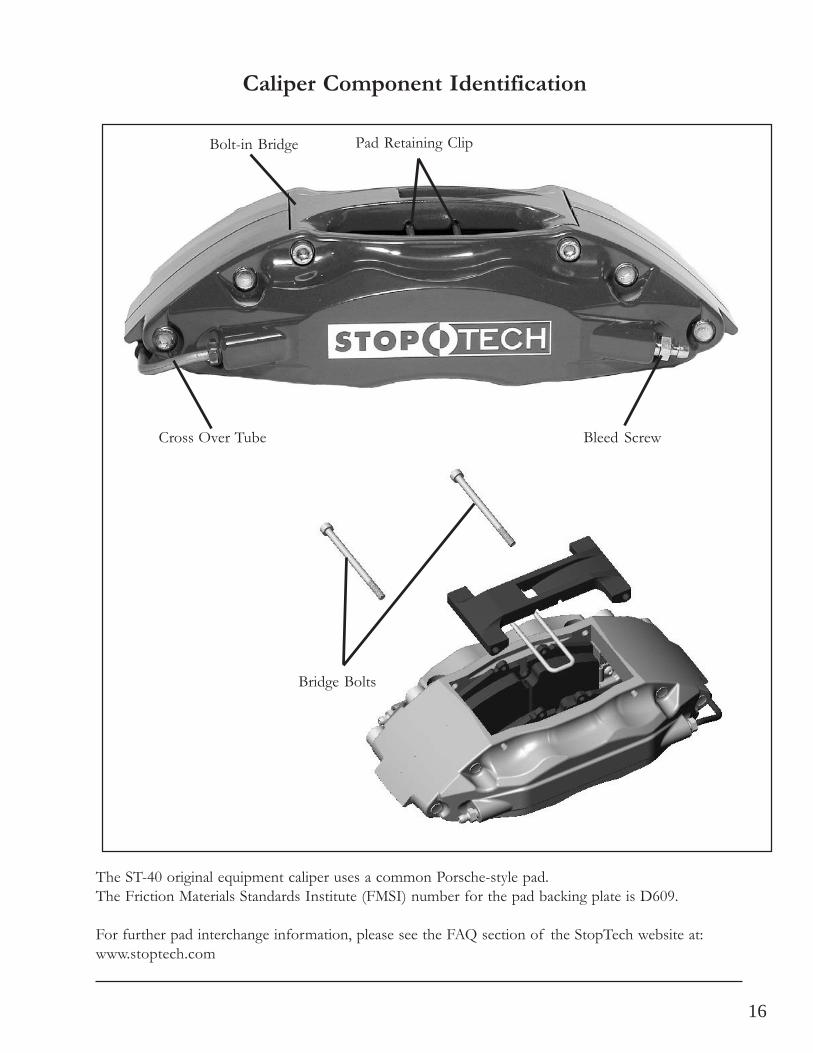
The ST-40 original equipment caliper uses a common Porsche-style pad.The Friction Materials Standards Institute (FMSI) number for the pad backing plate is D609.
For further pad interchange information, please see the FAQ section of the StopTech website at:www.stoptech.com
Caliper Component Identification
Cross Over Tube
Pad Retaining ClipBolt-in Bridge
Bleed Screw
Bridge Bolts
17
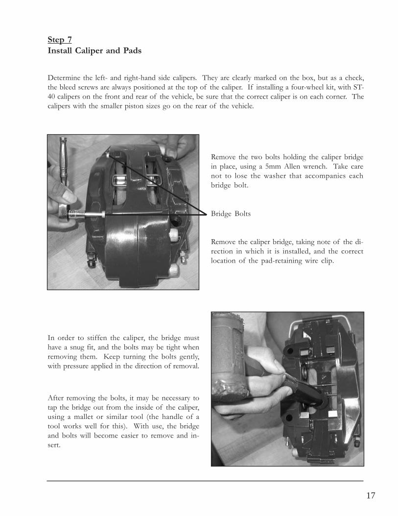
Remove the two bolts holding the caliper bridgein place, using a 5mm Allen wrench. Take carenot to lose the washer that accompanies eachbridge bolt.
Remove the caliper bridge, taking note of the di-rection in which it is installed, and the correctlocation of the pad-retaining wire clip.
Bridge Bolts
Determine the left- and right-hand side calipers. They are clearly marked on the box, but as a check,the bleed screws are always positioned at the top of the caliper. If installing a four-wheel kit, with ST-40 calipers on the front and rear of the vehicle, be sure that the correct caliper is on each corner. Thecalipers with the smaller piston sizes go on the rear of the vehicle.
Step 7Install Caliper and Pads
In order to stiffen the caliper, the bridge musthave a snug fit, and the bolts may be tight whenremoving them. Keep turning the bolts gently,with pressure applied in the direction of removal.
After removing the bolts, it may be necessary totap the bridge out from the inside of the caliper,using a mallet or similar tool (the handle of atool works well for this). With use, the bridgeand bolts will become easier to remove and in-sert.
18
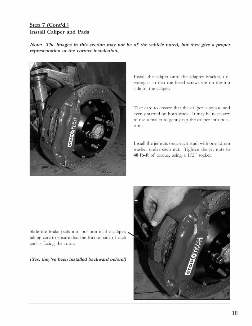
Install the caliper onto the adapter bracket, ori-enting it so that the bleed screws are on the topside of the caliper.
Slide the brake pads into position in the caliper,taking care to ensure that the friction side of eachpad is facing the rotor.
Step 7 (Cont’d.)Install Caliper and Pads
(Yes, they’ve been installed backward before!)
Take care to ensure that the caliper is square andevenly started on both studs. It may be necessaryto use a mallet to gently tap the caliper into posi-tion.
Install the jet nuts onto each stud, with one 12mmwasher under each nut. Tighten the jet nuts to40 lb-ft of torque, using a 1/2” socket.
Note: The images in this section may not be of the vehicle noted, but they give a properrepresentation of the correct installation.
19
Step 7 (Cont’d.)Install Caliper and Pads
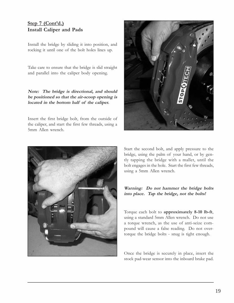
Note: The bridge is directional, and shouldbe positioned so that the air-scoop opening islocated in the bottom half of the caliper.
Install the bridge by sliding it into position, androcking it until one of the bolt holes lines up.
Torque each bolt to approximately 8-10 lb-ft,using a standard 5mm Allen wrench. Do not usea torque wrench, as the use of anti-seize com-pound will cause a false reading. Do not over-torque the bridge bolts - snug is tight enough.
Warning: Do not hammer the bridge boltsinto place. Tap the bridge, not the bolts!
Start the second bolt, and apply pressure to thebridge, using the palm of your hand, or by gen-tly tapping the bridge with a mallet, until thebolt engages in the hole. Start the first few threads,using a 5mm Allen wrench.
Insert the first bridge bolt, from the outside ofthe caliper, and start the first few threads, using a5mm Allen wrench.
Take care to ensure that the bridge is slid straightand parallel into the caliper body opening.
Once the bridge is securely in place, insert thestock pad-wear sensor into the inboard brake pad.
20
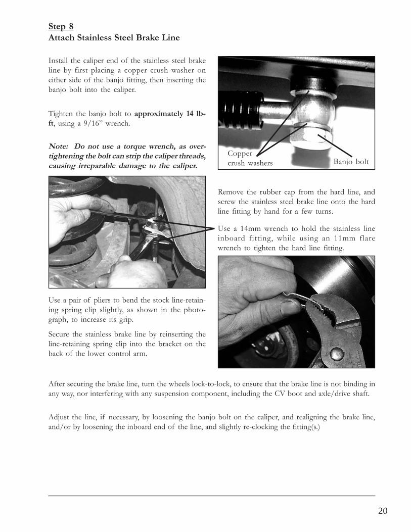
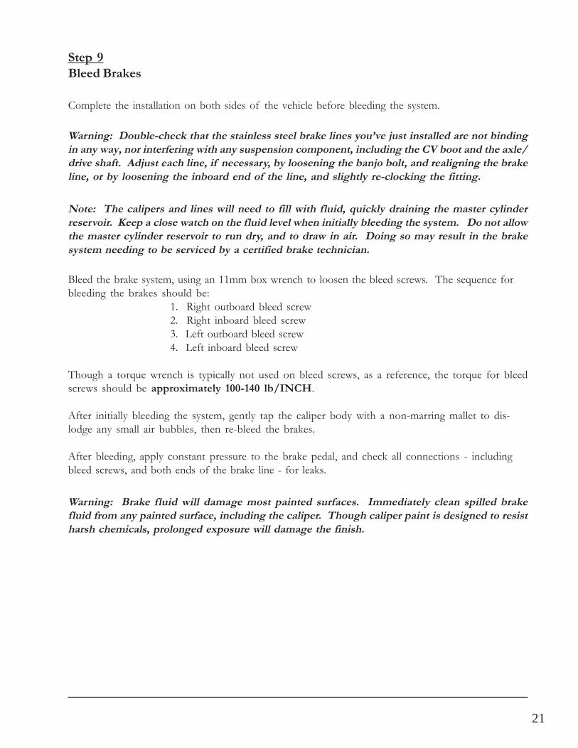
Install the caliper end of the stainless steel brakeline by first placing a copper crush washer oneither side of the banjo fitting, then inserting thebanjo bolt into the caliper.
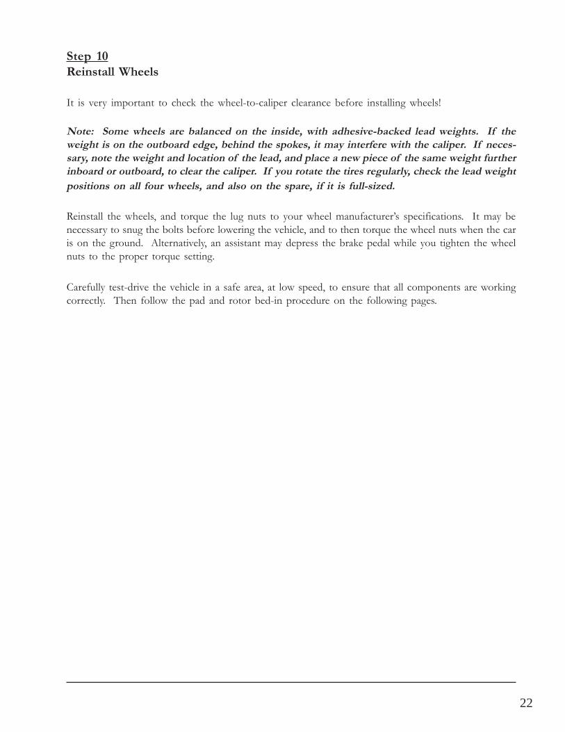
Remove the rubber cap from the hard line, andscrew the stainless steel brake line onto the hardline fitting by hand for a few turns.
Step 8Attach Stainless Steel Brake Line
Tighten the banjo bolt to approximately 14 lb-ft, using a 9/16” wrench.
Note: Do not use a torque wrench, as over-tightening the bolt can strip the caliper threads,causing irreparable damage to the caliper.
Use a 14mm wrench to hold the stainless lineinboard fitting, while using an 11mm flarewrench to tighten the hard line fitting.
Use a pair of pliers to bend the stock line-retain-ing spring clip slightly, as shown in the photo-graph, to increase its grip.
Secure the stainless brake line by reinserting theline-retaining spring clip into the bracket on theback of the lower control arm.
Coppercrush washers Banjo bolt
After securing the brake line, turn the wheels lock-to-lock, to ensure that the brake line is not binding inany way, nor interfering with any suspension component, including the CV boot and axle/drive shaft.
Adjust the line, if necessary, by loosening the banjo bolt on the caliper, and realigning the brake line,and/or by loosening the inboard end of the line, and slightly re-clocking the fitting(s.)
21
Warning: Brake fluid will damage most painted surfaces. Immediately clean spilled brakefluid from any painted surface, including the caliper. Though caliper paint is designed to resistharsh chemicals, prolonged exposure will damage the finish.
Bleed the brake system, using an 11mm box wrench to loosen the bleed screws. The sequence forbleeding the brakes should be:
1. Right outboard bleed screw2. Right inboard bleed screw3. Left outboard bleed screw4. Left inboard bleed screw
Though a torque wrench is typically not used on bleed screws, as a reference, the torque for bleedscrews should be approximately 100-140 lb/INCH.
After initially bleeding the system, gently tap the caliper body with a non-marring mallet to dis-lodge any small air bubbles, then re-bleed the brakes.
After bleeding, apply constant pressure to the brake pedal, and check all connections - includingbleed screws, and both ends of the brake line - for leaks.
Note: The calipers and lines will need to fill with fluid, quickly draining the master cylinderreservoir. Keep a close watch on the fluid level when initially bleeding the system. Do not allowthe master cylinder reservoir to run dry, and to draw in air. Doing so may result in the brakesystem needing to be serviced by a certified brake technician.
Complete the installation on both sides of the vehicle before bleeding the system.
Step 9Bleed Brakes
Warning: Double-check that the stainless steel brake lines you’ve just installed are not bindingin any way, nor interfering with any suspension component, including the CV boot and the axle/drive shaft. Adjust each line, if necessary, by loosening the banjo bolt, and realigning the brakeline, or by loosening the inboard end of the line, and slightly re-clocking the fitting.
22
Reinstall the wheels, and torque the lug nuts to your wheel manufacturer’s specifications. It may benecessary to snug the bolts before lowering the vehicle, and to then torque the wheel nuts when the caris on the ground. Alternatively, an assistant may depress the brake pedal while you tighten the wheelnuts to the proper torque setting.
It is very important to check the wheel-to-caliper clearance before installing wheels!
Note: Some wheels are balanced on the inside, with adhesive-backed lead weights. If theweight is on the outboard edge, behind the spokes, it may interfere with the caliper. If neces-sary, note the weight and location of the lead, and place a new piece of the same weight furtherinboard or outboard, to clear the caliper. If you rotate the tires regularly, check the lead weightpositions on all four wheels, and also on the spare, if it is full-sized.
Carefully test-drive the vehicle in a safe area, at low speed, to ensure that all components are workingcorrectly. Then follow the pad and rotor bed-in procedure on the following pages.
Step 10Reinstall Wheels
23
(Continued on next page)
AeroRotorTM Installation & Bed-in Procedure
Wash Non-Plated AeroRotors with SOAPAND WATER before installation.
Bed-in your new pads and rotors by carefully ob-serving the procedure described on this and thefollowing page.
READ THIS NOWThe majority of brake system problems are due to improper installation and/or bed-in of the rotorsand pads. By reading and understanding the following, you will avoid the most common causes ofpoor brake performance and vibration. FAILURE TO READ AND UNDERSTAND THIS MAYCAUSE SERIOUS PERMANENT DAMAGE TO YOUR NEW ROTORS.
StopTech coats non-plated AeroRotors with a water-soluble, environmentally friendly rust inhibitorthat MUST be cleaned off before use. A non-plated rotor looks like bare metal, while plated rotorsare bright silver in color, and do not need to be washed. Even though you may not see a change in therotor color, if the rotor is not rusty, the rust inhibitor is there. Use soap and water, NOT BRAKECLEANER to wash the rotors. A small piece of Scotchbrite works well for scrubbing. When cleanedand rinsed properly, the surface of the rotor may show a light rust color, which is normal.
Bed-in of rotors and pads is critical to the optimum performance of your new brakes. When bedding-in new parts, you are not only heat cycling the pads, you are also depositing a layer of pad materialonto the rotor face. If not bedded-in properly, an uneven layer of pad material will be deposited ontothe rotor, causing vibration. Virtually every instance of a “warped” rotor is attributedto uneven pad deposition.
Typically, a heavy-braking street driver will experience approximately 1 to 1.1G’s of deceleration. Atthis rate, the ABS will be activated on such equipped vehicles. A moderate braking effort is needed toproperly bed-in rotors and pads. If ABS intervention or lock-up were represented as 100% brakeeffort, a stopping force of approximately 70-80%, just short of ABS intervention or lock-up, is ageneral estimate of the pedal effort you are trying to achieve.
Note: Plated rotors must be driven with gentle braking until the CAD plating is worn off of therotor faces BEFORE starting the bed-in procedure. Do not use brakes aggressively until theplating is worn off, typically after several miles of driving.
FAILURE TO READ, UNDERSTAND AND FOLLOW THESE PROCEDURESWILL CAUSE PERMANENT DAMAGE TO YOUR BRAKE ROTORS, AND WILLKEEP THE SYSTEM FROM WORKING AT ITS FULL CAPACITY.
24
Rotor and Pad Bed-in (Cont’d.)
After completing the installation, make a series of 10 stops from 60 to 5-10 MPH. At the end of eachstop, immediately accelerate to 60 again for the next stop. Run all stops in one cycle.
During the 60 to 5-10 MPH cycle of stops, the exact speed is not critical. Accelerate to approximately60, then begin braking. As you approach 5-10 MPH, it is not necessary to watch the speedometer.Keep your eyes on the road, and approximate your speed at the end of each stop. DO NOT COMETO A COMPLETE STOP, WHILE LEAVING YOUR FOOT ON THE BRAKE PEDAL, AS YOUMAY IMPRINT PAD MATERIAL ONTO THE ROTOR, CAUSING A VIBRATION.
If racing or higher-performance pads are being used, add four stops from 80 to 5-10 MPH, andif full race pads are being used, add four stops from 100 to 5-10 MPH.
There are several indicators to look for while bedding-in the system:
On the 8th or 9th stop, there should be a distinct smell from the brakes. Smoke may also be evidentafter several stops.
Also on the 8th or 9th stop, some friction material will experience “green fade.” This is a slight fadingof the brakes. The fade will stabilize, but will not completely go away until the brakes have cooled.
After the bed-in cycle is finished, there will be a blue tint on the rotor, with a light gray film on therotor face. The blue tint indicates that the rotor has reached the proper bed-in temperature, and thegray film is pad material starting to transfer onto the rotor face. This is normal!
After the first bed-in cycle shown above, the brakes will still not be operating attheir best capacity. A second or third bed-in cycle is typically necessary before thebrakes really start to “come in.” A “cycle” is a series of stops with a cool down inbetween each cycle.
StopTech does not endorse speeding on public roads. If going above the legal speedlimit, do so in a safe area, away from traffic, and at your own risk.
After the final stop of each cycle, drive as much as possible without using the brakes, to cool off thesystem. Ideally, the brakes should be allowed to cool to ambient temperature before using themagain.
DO NOT COME TO A COMPLETE STOP WHEN THE SYSTEM IS HOT, WHILE LEAVINGYOUR FOOT ON THE BRAKE PEDAL. PAD MATERIAL MAY TRANSFER ONTO THEROTOR, CAUSING A VIBRATION.
Note: Bedding-in of pads should not be done in poor weather conditions, nor on wet roads.
Thank you for selecting StopTech.
We realize that you had a choice when selecting a big brake upgrade for your vehicle,and we know that you’ll be happy with our system.
We proudly support our fine products. For any assistance orquestions, please contact our Technical Support Department
at(310) 218-1091 or e-mail us at