Embed Size (px)
Citation preview
1
Do not store or use gasoline or other flammable vapors and liquids in the vicinity of this or any other appliance.WHAT TO DO IF YOU SMELL GAS • Do not try to light any appliance. • Do not touch any electrical switch; do not use any phone in your building. • Immediately call your gas supplier from a neighbor’s phone. Follow the gas supplier’s instructions. • If you cannot reach your gas supplier, call the fire department.Installation and service must be performed by a qualified installer, service agency or the gas supplier.
WARNING: If the information in theseinstructions is not followed exactly, a fire or explosion may result causing property damage, personal injury or death.
INSTALLER:• AFFIX THESE INSTRUCTIONS TO OR ADJACENT
TO THE WATER HEATER.OWNER:• RETAIN THESE INSTRUCTIONS AND WARRANTY
FOR FUTURE REFERENCE. RETAIN THE ORIGINAL RECEIPT AS PROOF OF PURCHASE.
Table of Contents ...................................................... 2
InstallationInstructions and
Use & Care GuideTo obtain technical, warranty, or service assistance during or after the installation of this water heater, visit our website at:
http://www.whirlpoolwaterheatersupport.comor call toll free
1-877-817-6750
When calling for assistance, please have the following information ready:
1. Model number2. 7 digit product number3. Serial number4. Date of installation5. Place of purchase
Gas Water HeaterHigh Efficiency
Atmospheric Vent
W10286887 316934-003July 2011
LOW LEADCOMPLIANT
2
Your safety and the safety of others are very important.We have provided many important safety messages in this manual and on your appliance. Always read and obey all safety messages.
This is the safety alert symbol.This symbol alerts you to potential hazards that can kill or hurt you and others.All safety messages will follow the safety alert symbol and either the word “DANGER” or“WARNING.” These words mean:
You can be killed or seriously injured if you don’t immediately follow instructions.You can be killed or seriously injured if you don’tfollow instructions.All safety messages will tell you what the potential hazard is,
tell you how to reduce the chance of injury, and tell you what can happen if the instructions are not followed.
Important Instructions• Do not use this appliance if any part has been under water. Immediately call a qualified service person. Water
heaters subjected to flood conditions or any time the gas controls, main burner or pilot have been submerged in water require replacement of the entire water heater.
• Hydrogen gas can be produced in a hot water system that has not been used for a long period of time (generally two weeks or more). Hydrogen gas is extremely flammable and can ignite when exposed to a spark or flame. To prevent the possibility of injury under these conditions, we recommend the hot water faucet be opened for several minutes at the kitchen sink before using any electrical appliance which is connected to the hot water system. If hydrogen is present, there will probably be an unusual sound such as air escaping through the faucet as water begins to flow. Do not smoke or have any open flame near the faucet at the time it is open.
The California Safe Drinking Water and Toxic Enforcement Act requires the Governor of California to publish a list of substances known to the State of California to cause cancer, birth defects, or other reproductive harm, and requires businesses to warn of potential exposure to such substances.WARNING: This product contains a chemical known to the State of California to cause cancer, birth defects, or other reproductive harm. This appliance can cause low-level exposure to some of the substances included in the Act.
WATER HEATER SAFETY
Table Of ContentsWater Heater Safety .............................................................................. 1-2Installing Your Gas Water Heater ........................................................ 3-17 Unpacking the Water Heater .......................................................... 3 Location Requirements ................................................................... 4 Gas Supply ..................................................................................... 6 Combustion Air Supply and Ventilation .......................................... 7 Water System Piping .................................................................... 12 Installation Checklist ..................................................................... 17Operating Your Water Heater ............................................................ 18-21 Lighting Instructions ................................................................. 18-21 Operational Conditions ................................................................. 21Maintenance of Your Water Heater ...................................................23-25Troubleshooting Charts .....................................................................26-31Repair Parts Illustration .....................................................................32-33
PAGE
3
INSTALLING YOUR GAS WATER HEATERImportant Information About This Water HeaterThis gas water heater was manufactured to voluntary safety standards to reduce the likelihood of a flammable vapor ignition incident. New technology used in meeting these standards makes this product more sensitive to installation errors or improper installation environments. Please review the Installation Checklist found at the end of the installation instructions section and make any required installation upgrades or changes.
This product is certifield to comply with a maximum weighted average of 0.25% lead content as required in some areas.
Consumer InformationThis water heater is design-certified by CSA International as a Category I, non-direct vented water heater which takes its combustion air either from the installation area or from air ducted to the unit from the outside.This water heater must be installed according to all lo-cal and state codes or, in the absence of local and state codes, the “National Fuel Gas Code”, ANSI Z223.1(NFPA 54)- latest edition. This is available from the following:CSA America, Inc.8501 East Pleasant Valley RoadCleveland, OH 44131National Fire Protection Association1 Batterymarch ParkQuincy, MA 02269Check your phone listings for the local authorities having jurisdiction over your installation.
Consumer ResponsibilitiesThis manual has been prepared to acquaint you with the installation, operation, and maintenance of your gas water heater and provide important safety information in these areas. Read all of the instructions thoroughly before attempting the installation or operation of this water heater. Do not discard this manual. You or future users of this water heater will need it for future reference.Service to the Flame Lock™ Safety System should only be performed by a qualified person.Examples of a qualified person include: licensed plumbers, authorized gas company personnel, and authorized service personnel.IMPORTANT: The manufacturer and seller of this water heater will not be liable for any damages, injuries, or deaths caused by failure to comply with the installation and operating instructions outlined in this manual.
If you lack the necessary skills required to properly install this water heater, or you have difficulty following the instructions, you should not proceed but have a qualified person perform the installation of this water heater. Massachusetts code requires this water heater to be installed in accordance with Massachusetts Plumbing and Fuel Gas Code 248 CMR Section 2.00 and 5.00. A data plate identifying your water heater can be found next to the gas control valve/thermostat. When referring to your water heater, always have the information listed on the data plate readily available. Retain your original receipt as proof of purchase.Keep combustibles such as boxes, magazines, clothes, etc., away from water heater area.
High Altitude InstallationThis water heater should not be installed for operation at elevations above 10,100 ft. (3,078 m).
Unpacking the Water Heater
IMPORTANT: Do not remove any permanent instructions, labels, or the data label from either the outside of the water heater or on the inside of water heater panels.• Remove exterior packaging and place installation com-
ponents aside.• Inspect all parts for damage prior to installation and
start-up.• Completely read all instructions before attempting to
assemble and install this product.• After installation, dispose of/recycle all packaging
materials.
WARNINGExcessive Weight Hazard
Use two or more people to move and install water heater.Failure to do can result in back or other injury.
4
Location Requirements
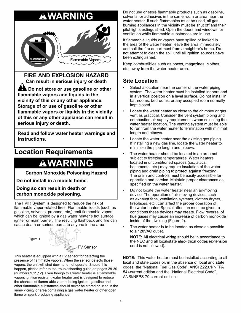
The FVIR System is designed to reduce the risk of flammable vapor-related fires. Flammable liquids (such as gasoline, solvents, propane, etc,) emit flammable vapors which can be ignited by a gas water heater’s hot surface igniter or main burner. The resulting flashback and fire can cause death or serious burns to anyone in the area.
This heater is equipped with a FV sensor for detecting the presence of flammable vapors. When the sensor detects those vapors, the unit will shut down and not operate. Should this happen, please refer to the troubleshooting guide on pages 29-30 (numbers 9,11,12). Even though this water heater is a flammable vapors ignition resistant water heater and is designed to reduce the chances of flamm-able vapors being ignited, gasoline and other flammable substances should never be stored or used in the same vicinity or area containing a gas water heater or other open flame or spark producing appliance.
FIRE AND EXPLOSION HAZARDCan result in serious injury or death
Do not store or use gasoline or other flammable vapors and liquids in the vicinity of this or any other appliance. Storage of or use of gasoline or other flammable vapors or liquids in the vicinity of this or any other appliance can result in serious injury or death.
Flammable VaporsFLAMMABLES
Read and follow water heater warnings and instructions.
WARNING
Carbon Monoxide Poisoning HazardDo not install in a mobile home.Doing so can result in death or carbon monoxide poisoning.
WARNING
Do not use or store flammable products such as gasoline, solvents, or adhesives in the same room or area near the water heater. If such flammables must be used, all gas burning appliances in the vicinity must be shut off and their pilot lights extinguished. Open the doors and windows for ventilation while flammable substances are in use. If flammable liquids or vapors have spilled or leaked in the area of the water heater, leave the area immediately and call the fire department from a neighbor’s home. Do not attempt to clean the spill until all ignition sources have been extinguished.Keep combustibles such as boxes, magazines, clothes, etc. away from the water heater area.
Site Location• Select a location near the center of the water piping
system. The water heater must be installed indoors and in a vertical position on a level surface. Do not install in bathrooms, bedrooms, or any occupied room normally kept closed.
• Locate the water heater as close to the chimney or gas vent as practical. Consider the vent system piping and combustion air supply requirements when selecting the water heater location. The venting system must be able to run from the water heater to termination with minimal length and elbows.
• Locate the water heater near the existing gas piping. If installing a new gas line, locate the water heater to minimize the pipe length and elbows.
• The water heater should be located in an area not subject to freezing temperatures. Water heaters located in unconditioned spaces (i.e., attics, basements, etc.) may require insulation of the water piping and drain piping to protect against freezing. The drain and controls must be easily accessible for operation and service. Maintain proper clearances as specified on the water heater.
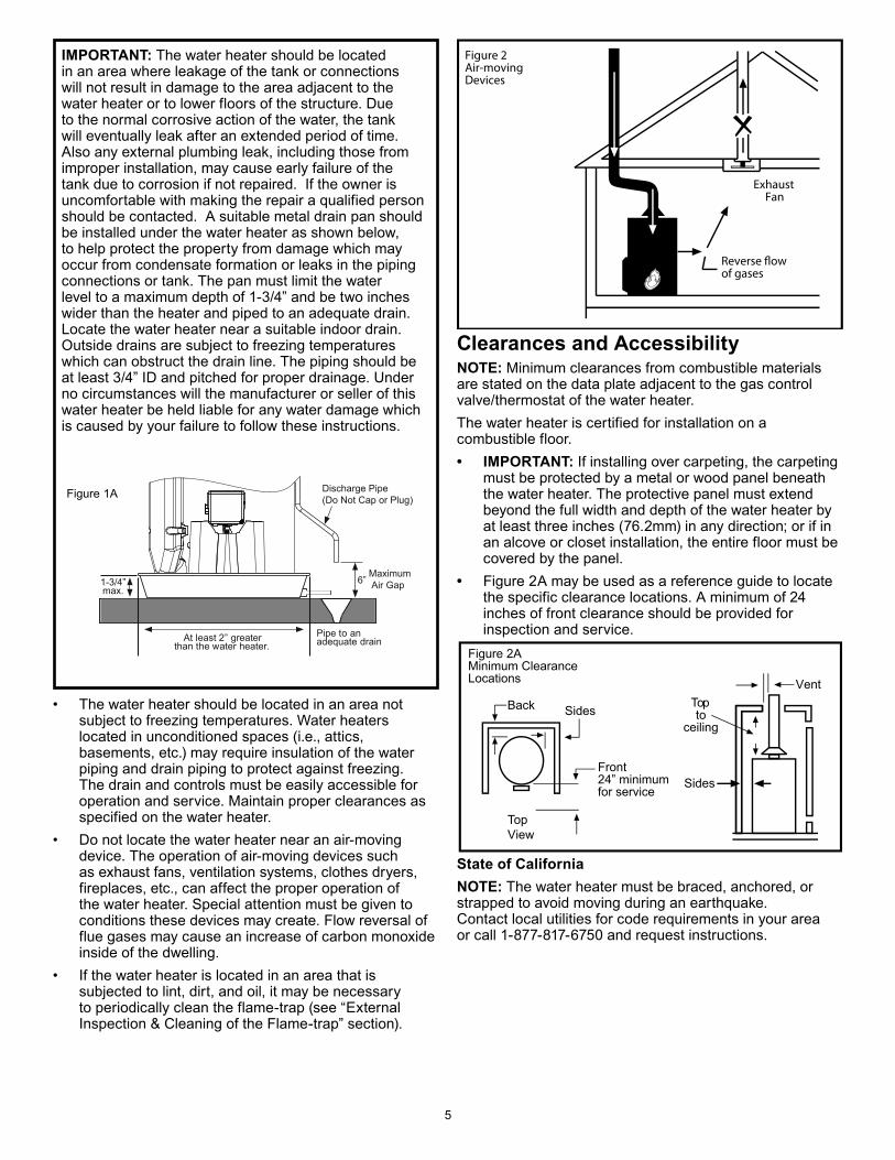
• Do not locate the water heater near an air-moving device. The operation of air-moving devices such as exhaust fans, ventilation systems, clothes dryers, fireplaces, etc., can affect the proper operation of the water heater. Special attention must be given to conditions these devices may create. Flow reversal of flue gases may cause an increase of carbon monoxide inside of the dwelling (Figure 2).
• The water heater is to be located as close as possible to a 120VAC outlet.
NOTE: All electrical wiring should be in accordance to the NEC and all local/state elec- trical codes (extension cord is not allowed).
NOTE: This water heater must be installed according to all local and state codes or, in the absence of local and state codes, the “National Fuel Gas Code”, ANSI Z223.1(NFPA 54)-current edition and the “National Electrical Code”, ANSI/NFPS 70 current edition.
FV Sensor
Figure 1
5
IMPORTANT: The water heater should be located in an area where leakage of the tank or connections will not result in damage to the area adjacent to the water heater or to lower floors of the structure. Due to the normal corrosive action of the water, the tank will eventually leak after an extended period of time. Also any external plumbing leak, including those from improper installation, may cause early failure of the tank due to corrosion if not repaired. If the owner is uncomfortable with making the repair a qualified person should be contacted. A suitable metal drain pan should be installed under the water heater as shown below, to help protect the property from damage which may occur from condensate formation or leaks in the piping connections or tank. The pan must limit the water level to a maximum depth of 1-3/4” and be two inches wider than the heater and piped to an adequate drain. Locate the water heater near a suitable indoor drain. Outside drains are subject to freezing temperatures which can obstruct the drain line. The piping should be at least 3/4” ID and pitched for proper drainage. Under no circumstances will the manufacturer or seller of this water heater be held liable for any water damage which is caused by your failure to follow these instructions.
Reverse flow of gases
ExhaustFan
Figure 2Air-movingDevices
Back Sides
Sides
Topto
ceiling
Vent
Front24” minimum for service
Figure 2AMinimum ClearanceLocations
TViewop
Clearances and AccessibilityNOTE: Minimum clearances from combustible materials are stated on the data plate adjacent to the gas control valve/thermostat of the water heater.The water heater is certified for installation on a combustible floor.• IMPORTANT: If installing over carpeting, the carpeting
must be protected by a metal or wood panel beneath the water heater. The protective panel must extend beyond the full width and depth of the water heater by at least three inches (76.2mm) in any direction; or if in an alcove or closet installation, the entire floor must be covered by the panel.
• Figure 2A may be used as a reference guide to locate the specific clearance locations. A minimum of 24 inches of front clearance should be provided for inspection and service.
State of CaliforniaNOTE: The water heater must be braced, anchored, or strapped to avoid moving during an earthquake. Contact local utilities for code requirements in your area or call 1-877-817-6750 and request instructions.
• The water heater should be located in an area not subject to freezing temperatures. Water heaters located in unconditioned spaces (i.e., attics, basements, etc.) may require insulation of the water piping and drain piping to protect against freezing. The drain and controls must be easily accessible for operation and service. Maintain proper clearances as specified on the water heater.
• Do not locate the water heater near an air-moving device. The operation of air-moving devices such as exhaust fans, ventilation systems, clothes dryers, fireplaces, etc., can affect the proper operation of the water heater. Special attention must be given to conditions these devices may create. Flow reversal of flue gases may cause an increase of carbon monoxide inside of the dwelling.
• If the water heater is located in an area that is subjected to lint, dirt, and oil, it may be necessary to periodically clean the flame-trap (see “External Inspection & Cleaning of the Flame-trap” section).
1-3/4” max.
Pipe to an adequate drainAt least 2” greater
than the water heater.
Maximum Air Gap6”
Discharge Pipe(Do Not Cap or Plug)Figure 1A
6
Gas Supply
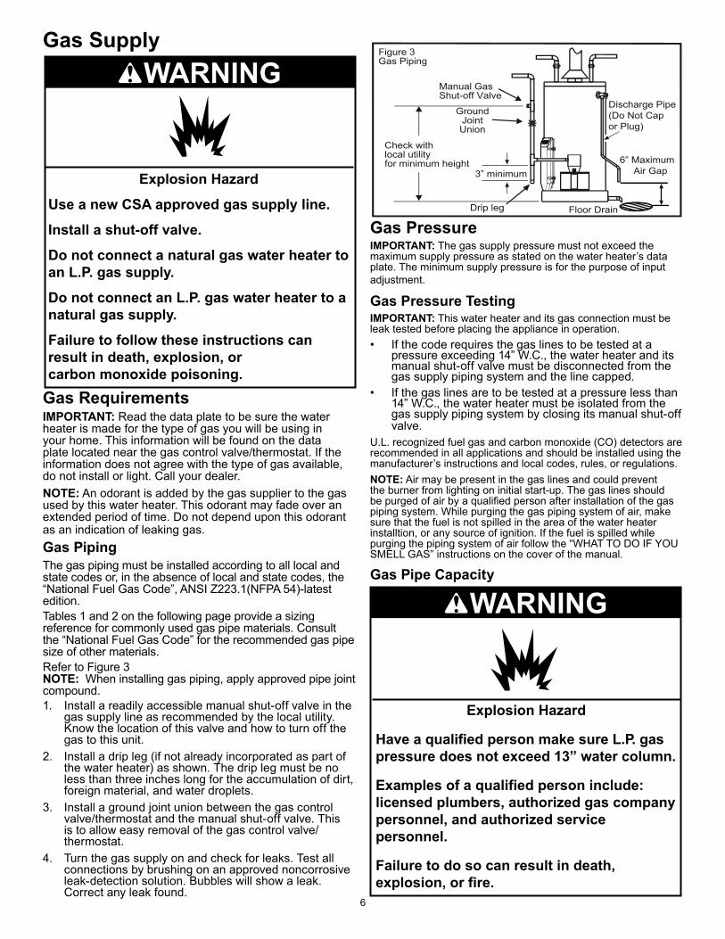
Gas RequirementsIMPORTANT: Read the data plate to be sure the water heater is made for the type of gas you will be using in your home. This information will be found on the data plate located near the gas control valve/thermostat. If the information does not agree with the type of gas available, do not install or light. Call your dealer.NOTE: An odorant is added by the gas supplier to the gas used by this water heater. This odorant may fade over an extended period of time. Do not depend upon this odorant as an indication of leaking gas.Gas PipingThe gas piping must be installed according to all local and state codes or, in the absence of local and state codes, the “National Fuel Gas Code”, ANSI Z223.1(NFPA 54)-latest edition.Tables 1 and 2 on the following page provide a sizing reference for commonly used gas pipe materials. Consult the “National Fuel Gas Code” for the recommended gas pipe size of other materials.Refer to Figure 3NOTE: When installing gas piping, apply approved pipe joint compound.1. Install a readily accessible manual shut-off valve in the
gas supply line as recommended by the local utility. Know the location of this valve and how to turn off the gas to this unit.
2. Install a drip leg (if not already incorporated as part of the water heater) as shown. The drip leg must be no less than three inches long for the accumulation of dirt, foreign material, and water droplets.
3. Install a ground joint union between the gas control valve/thermostat and the manual shut-off valve. This is to allow easy removal of the gas control valve/ thermostat.
4. Turn the gas supply on and check for leaks. Test all connections by brushing on an approved noncorrosive leak-detection solution. Bubbles will show a leak. Correct any leak found.
Figure 3Gas Piping
Manual GasShut-off Valve
GroundJointUnion
3” minimum
Check withlocal utilityfor minimum height
Drip leg
6” Maximum Air Gap
Discharge Pipe(Do Not Capor Plug)
Floor Drain
Gas PressureIMPORTANT: The gas supply pressure must not exceed the maximum supply pressure as stated on the water heater’s data plate. The minimum supply pressure is for the purpose of input adjustment.
Gas Pressure TestingIMPORTANT: This water heater and its gas connection must be leak tested before placing the appliance in operation.• If the code requires the gas lines to be tested at a
pressure exceeding 14” W.C., the water heater and its manual shut-off valve must be disconnected from the gas supply piping system and the line capped.
• If the gas lines are to be tested at a pressure less than 14” W.C., the water heater must be isolated from the gas supply piping system by closing its manual shut-off valve.
U.L. recognized fuel gas and carbon monoxide (CO) detectors are recommended in all applications and should be installed using the manufacturer’s instructions and local codes, rules, or regulations.NOTE: Air may be present in the gas lines and could prevent the burner from lighting on initial start-up. The gas lines should be purged of air by a qualified person after installation of the gas piping system. While purging the gas piping system of air, make sure that the fuel is not spilled in the area of the water heater installtion, or any source of ignition. If the fuel is spilled while purging the piping system of air follow the “WHAT TO DO IF YOU SMELL GAS” instructions on the cover of the manual.
Gas Pipe Capacity
Explosion Hazard
Use a new CSA approved gas supply line.
Install a shut-off valve.
Do not connect a natural gas water heater to an L.P. gas supply.
Do not connect an L.P. gas water heater to a natural gas supply.
Failure to follow these instructions can result in death, explosion, or carbon monoxide poisoning.
WARNING
Explosion Hazard
Have a qualified person make sure L.P. gas pressure does not exceed 13” water column.
Examples of a qualified person include: licensed plumbers, authorized gas company personnel, and authorized service personnel.
Failure to do so can result in death, explosion, or fire.
WARNING
7
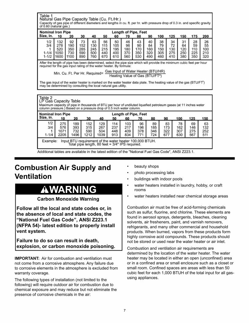
Combustion Air Supply and Ventilation
IMPORTANT: Air for combustion and ventilation must not come from a corrosive atmosphere. Any failure due to corrosive elements in the atmosphere is excluded from warranty coverage.The following types of installation (not limited to the following) will require outdoor air for combustion due to chemical exposure and may reduce but not eliminate the presence of corrosive chemicals in the air:
• beauty shops• photo processing labs• buildings with indoor pools • water heaters installed in laundry, hobby, or craft
rooms• water heaters installed near chemical storage areas
Combustion air must be free of acid-forming chemicals such as sulfur, fluorine, and chlorine. These elements are found in aerosol sprays, detergents, bleaches, cleaning solvents, air fresheners, paint, and varnish removers, refrigerants, and many other commercial and household products. When burned, vapors from these products form highly corrosive acid compounds. These products should not be stored or used near the water heater or air inlet.Combustion and ventilation air requirements are determined by the location of the water heater. The water heater may be located in either an open (unconfined) area or in a confined area or small enclosure such as a closet or small room. Confined spaces are areas with less than 50 cubic feet for each 1,000 BTUH of the total input for all gas-using appliances.
Carbon Monoxide Warning
Follow all the local and state codes or, in the absence of local and state codes, the “National Fuel Gas Code”, ANSI Z223.1 (NFPA 54)- latest edition to properly install vent system.
Failure to do so can result in death, explosion, or carbon monoxide poisoning.
WARNING
8
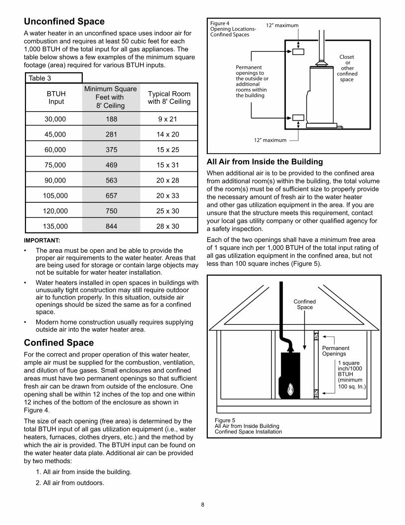
Unconfined SpaceA water heater in an unconfined space uses indoor air for combustion and requires at least 50 cubic feet for each 1,000 BTUH of the total input for all gas appliances. The table below shows a few examples of the minimum square footage (area) required for various BTUH inputs.
30,000
45,000
60,000
75,000
90,000
105,000
120,000
135,000
188
281
375
469
563
657
750
844
9 x 21
14 x 20
15 x 25
15 x 31
20 x 28
20 x 33
25 x 30
28 x 30
Typical Roomwith 8' Ceiling
Minimum SquareFeet with 8' Ceiling
BTUHInput
Table 3
IMPORTANT:• The area must be open and be able to provide the
proper air requirements to the water heater. Areas that are being used for storage or contain large objects may not be suitable for water heater installation.
• Water heaters installed in open spaces in buildings with unusually tight construction may still require outdoor air to function properly. In this situation, outside air openings should be sized the same as for a confined space.
• Modern home construction usually requires supplying outside air into the water heater area.
Confined Space For the correct and proper operation of this water heater, ample air must be supplied for the combustion, ventilation, and dilution of flue gases. Small enclosures and confined areas must have two permanent openings so that sufficient fresh air can be drawn from outside of the enclosure. One opening shall be within 12 inches of the top and one within 12 inches of the bottom of the enclosure as shown in Figure 4.The size of each opening (free area) is determined by the total BTUH input of all gas utilization equipment (i.e., water heaters, furnaces, clothes dryers, etc.) and the method by which the air is provided. The BTUH input can be found on the water heater data plate. Additional air can be provided by two methods:
1. All air from inside the building.2. All air from outdoors.
Figure 4Opening Locations-Confined Spaces
12” maximum
Permanent openings to the outside or additional rooms within the building
Closet or
otherconfined
space
12” maximum
All Air from Inside the BuildingWhen additional air is to be provided to the confined area from additional room(s) within the building, the total volume of the room(s) must be of sufficient size to properly provide the necessary amount of fresh air to the water heater and other gas utilization equipment in the area. If you are unsure that the structure meets this requirement, contact your local gas utility company or other qualified agency for a safety inspection. Each of the two openings shall have a minimum free area of 1 square inch per 1,000 BTUH of the total input rating of all gas utilization equipment in the confined area, but not less than 100 square inches (Figure 5).
ConfinedSpace
Figure 5 All Air from Inside BuildingConfined Space Installation
PermanentOpenings
1 squareinch/1000BTUH(minimum100 sq. In.)
9
Direct tooutdoors
Vertical ducts
Horizontal ducts
Figure 6
Figure 7
Figure 8
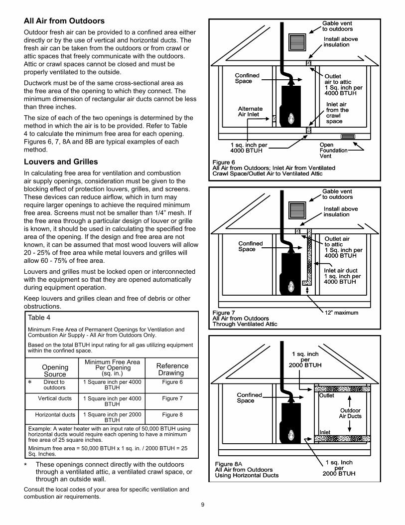
Table 4Minimum Free Area of Permanent Openings for Ventilation and Combustion Air Supply - All Air from Outdoors Only.
Based on the total BTUH input rating for all gas utilizing equipment within the confined space.
Opening Source
1 Square inch per 4000BTUH
1 Square inch per 4000BTUH
1 Square inch per 2000BTUH
Minimum Free Area Per Opening
(sq. in.)Reference Drawing
Example: A water heater with an input rate of 50,000 BTUH using horizontal ducts would require each opening to have a minimum free area of 25 square inches.Minimum free area = 50,000 BTUH x 1 sq. in. / 2000 BTUH = 25 Sq. Inches.
All Air from OutdoorsOutdoor fresh air can be provided to a confined area either directly or by the use of vertical and horizontal ducts. The fresh air can be taken from the outdoors or from crawl or attic spaces that freely communicate with the outdoors. Attic or crawl spaces cannot be closed and must be properly ventilated to the outside. Ductwork must be of the same cross-sectional area as the free area of the opening to which they connect. The minimum dimension of rectangular air ducts cannot be less than three inches. The size of each of the two openings is determined by the method in which the air is to be provided. Refer to Table 4 to calculate the minimum free area for each opening. Figures 6, 7, 8A and 8B are typical examples of each method.
Louvers and GrillesIn calculating free area for ventilation and combustion air supply openings, consideration must be given to the blocking effect of protection louvers, grilles, and screens. These devices can reduce airflow, which in turn may require larger openings to achieve the required minimum free area. Screens must not be smaller than 1/4” mesh. If the free area through a particular design of louver or grille is known, it should be used in calculating the specified free area of the opening. If the design and free area are not known, it can be assumed that most wood louvers will allow 20 - 25% of free area while metal louvers and grilles will allow 60 - 75% of free area. Louvers and grilles must be locked open or interconnected with the equipment so that they are opened automatically during equipment operation. Keep louvers and grilles clean and free of debris or other obstructions.
* These openings connect directly with the outdoors through a ventilated attic, a ventilated crawl space, or through an outside wall.
Consult the local codes of your area for specific ventilation and combustion air requirements.
ConfinedSpace
Figure 8All Air from OutdoorsUsing Horizontal Ducts
OutdoorAir Ducts
Outlet
Inlet
1 sq. inchper
2000 BTUH
1 sq. inch per4000 BTUH
ConfinedSpace
Figure 6All Air from Outdoors; Inlet Air from VentilatedCrawl Space/Outlet Air to Ventilated Attic
Inlet airfrom thecrawlspace
Install aboveinsulation
Gable ventto outdoors
Outletair to attic1 Sq. inch per4000 BTUH
AlternateAir Inlet
OpenFoundationVent
ConfinedSpace
Figure 7All Air from OutdoorsThrough Ventilated Attic
Inlet air duct1 sq. inch per4000 BTUH
Install aboveinsulation
Gable ventto outdoors
Outlet airto attic1 Sq. inch per4000 BTUH
12” maximum
1 sq. Inchper
2000 BTUH
ConfinedSpace
FigureAll Air from OutdoorsUsing Horizontal Ducts
OutdoorAir Ducts
Outlet
Inlet
1 sq. inchper
2000 BTUH
1 sq. inch per4000 BTUH
ConfinedSpace
Figure 6All Air from Outdoors; Inlet Air from VentilatedCrawl Space/Outlet Air to Ventilated Attic
Inlet airfrom thecrawlspace
Install aboveinsulation
Gable ventto outdoors
Outletair to attic1 Sq. inch per4000 BTUH
AlternateAir Inlet
OpenFoundationVent
ConfinedSpace
Figure 7All Air from OutdoorsThrough Ventilated Attic
Inlet air duct1 sq. inch per4000 BTUH
Install aboveinsulation
Gable ventto outdoors
Outlet airto attic1 Sq. inch per4000 BTUH
12” maximum
1 sq. Inchper
2000 BTUH
8A
10
Vent Pipe SystemThis water heater uses a non-direct, single-pipe vent system to remove exhaust gases created by the burning of fossil fuels. Air for combustion is taken from the immediate water heater location or is ducted in from the outside (see “Combustion Air Supply and Ventilation” section).This water heater must be properly vented for the removal of exhaust gases to the outside atmosphere. Correct installation of the vent pipe system is mandatory for the proper and efficient operation of this water heater and is an important factor in the life of the unit.The vent pipe must be installed according to all local and state codes or, in the absence of local and state codes, the “National Fuel Gas Code”, ANSI Z223.1(NFPA 54)-latest edition. The vent pipe installation must not be obstructed so as to prevent the removal of exhaust gases to the outside atmosphere.IMPORTANT: The use of vent dampers is not recommended by the manufacturer of this water heater. Although some vent dampers are certified by CSA International, this certification applies to the vent damper device only and does not mean they are certified for use on this water heater.U.L. recognized fuel gas and carbon monoxide (CO) detectors are recommended in all applications and should be installed using the manufacturer’s instructions and local codes, rules, or regulations.IMPORTANT: If you lack the necessary skills required to properly install this venting system, you should not proceed, but get help from a qualified person.
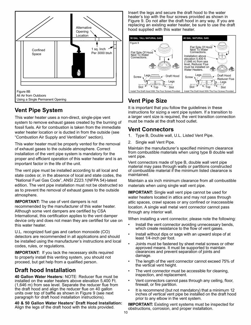
Draft hood Installation40 Gallon Water Heaters: NOTE: Reducer flue must be installed on the water heaters above elevation 5,400 Ft. (1,646 m) from sea level. Separate the reducer flue from the draft hood and align the reducer flue on 40 gallon units over top of baffle as shown in Figure 9 (see next paragraph for draft hood installation instructions).40 & 50 Gallon Water Heaters’ Draft Hood Installation: Align the legs of the draft hood with the slots provided.
Insert the legs and secure the draft hood to the water heater’s top with the four screws provided as shown in Figure 9. Do not alter the draft hood in any way. If you are replacing an existing water heater, be sure to use the draft hood supplied with this water heater.
Installation above elevation 5,400 ft. (1,646 m) from sea level, Reducer Flue must be installed on Water Heaters.
Flat Side Of Hood Next To Water Connections.
Draft Hood
Legs
Legs
SlotSlot TopInstall The Draft Hood With The Four Screws Provided.
Screw
Install The Draft Hood With The Four Screws Provided.
50 GAL. TALL NATURAL GAS 40 GAL. NATURAL GAS
Draft HoodLegsScrew
Legs
SlotTopSlot
Reducer Flue
Flat Side Of Hood Next To Water Connections.
Figure 9
Vent Pipe Size It is important that you follow the guidelines in these instructions for sizing a vent pipe system. If a transition to a larger vent size is required, the vent transition connection must be made at the draft hood outlet.
Vent Connectors1. Type B, Double wall, U.L. Listed Vent Pipe.2. Single wall Vent Pipe.Maintain the manufacturer’s specified minimum clearance from combustible materials when using type B double wall vent pipe.Vent connectors made of type B, double wall vent pipe material may pass through walls or partitions constructed of combustible material if the minimum listed clearance is maintained.Maintain a six inch minimum clearance from all combustible materials when using single wall vent pipe.IMPORTANT: Single wall vent pipe cannot be used for water heaters located in attics and may not pass through attic spaces, crawl spaces or any confined or inaccessible location. A single wall metal vent connector cannot pass through any interior wall.When installing a vent connector, please note the following:• Install the vent connector avoiding unnecessary bends,
which create resistance to the flow of vent gases.• Install without dips or sags with an upward slope of at
least 1/4-inch per foot.• Joints must be fastened by sheet metal screws or other
approved means. It must be supported to maintain clearances and prevent separation of joints and damage.
• The length of the vent connector cannot exceed 75% of the vertical vent height.
• The vent connector must be accessible for cleaning, inspection, and replacement.
• Vent connectors cannot pass through any ceiling, floor, firewall, or fire partition.
• It is recommend (but not mandatory) that a minimum 12 inches of vertical vent pipe be installed on the draft hood prior to any elbow in the vent system.
IMPORTANT: Existing vent systems must be inspected for obstructions, corrosion, and proper installation.
AlternativeOpeningLocation
1 sq. Inch Per 3000 btuh
ConfinedSpace
Figure 8BAll Air from Outdoors Using a Single Permanent Opening
11
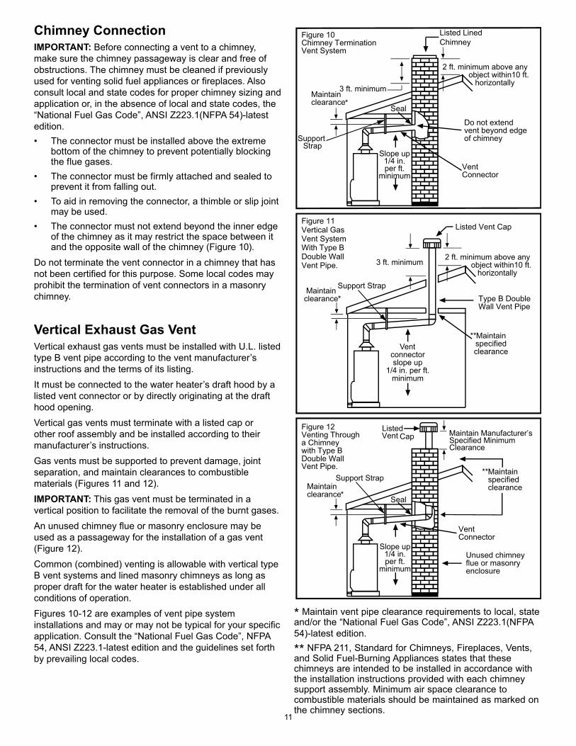
Chimney ConnectionIMPORTANT: Before connecting a vent to a chimney, make sure the chimney passageway is clear and free of obstructions. The chimney must be cleaned if previously used for venting solid fuel appliances or fireplaces. Also consult local and state codes for proper chimney sizing and application or, in the absence of local and state codes, the “National Fuel Gas Code”, ANSI Z223.1(NFPA 54)-latest edition.• The connector must be installed above the extreme
bottom of the chimney to prevent potentially blocking the flue gases.
• The connector must be firmly attached and sealed to prevent it from falling out.
• To aid in removing the connector, a thimble or slip joint may be used.
• The connector must not extend beyond the inner edge of the chimney as it may restrict the space between it and the opposite wall of the chimney (Figure 10).
Do not terminate the vent connector in a chimney that has not been certified for this purpose. Some local codes may prohibit the termination of vent connectors in a masonry chimney.
Vertical Exhaust Gas VentVertical exhaust gas vents must be installed with U.L. listed type B vent pipe according to the vent manufacturer’s instructions and the terms of its listing. It must be connected to the water heater’s draft hood by a listed vent connector or by directly originating at the draft hood opening.Vertical gas vents must terminate with a listed cap or other roof assembly and be installed according to their manufacturer’s instructions.Gas vents must be supported to prevent damage, joint separation, and maintain clearances to combustible materials (Figures 11 and 12).IMPORTANT: This gas vent must be terminated in a vertical position to facilitate the removal of the burnt gases.An unused chimney flue or masonry enclosure may be used as a passageway for the installation of a gas vent (Figure 12).Common (combined) venting is allowable with vertical type B vent systems and lined masonry chimneys as long as proper draft for the water heater is established under all conditions of operation. Figures 10-12 are examples of vent pipe system installations and may or may not be typical for your specific application. Consult the “National Fuel Gas Code”, NFPA 54, ANSI Z223.1-latest edition and the guidelines set forth by prevailing local codes.
* Maintain vent pipe clearance requirements to local, state and/or the “National Fuel Gas Code”, ANSI Z223.1(NFPA 54)-latest edition.
** NFPA 211, Standard for Chimneys, Fireplaces, Vents, and Solid Fuel-Burning Appliances states that these chimneys are intended to be installed in accordance with the installation instructions provided with each chimney support assembly. Minimum air space clearance to combustible materials should be maintained as marked on the chimney sections.
Slope up 1/4 in. per ft.
minimum
3 ft. minimum
2 ft. minimum above any object within10 ft. horizontally
2 ft. minimum above any object within10 ft. horizontally
3 ft. minimum
Vent connector slope up
1/4 in. per ft. minimum
Slope up 1/4 in. per ft.
minimum
*
*
*
**
**
Listed Lined Chimney
Support Strap
Support Strap
Support Strap
Maintain Manufacturer’sSpecified MinimumClearance
12
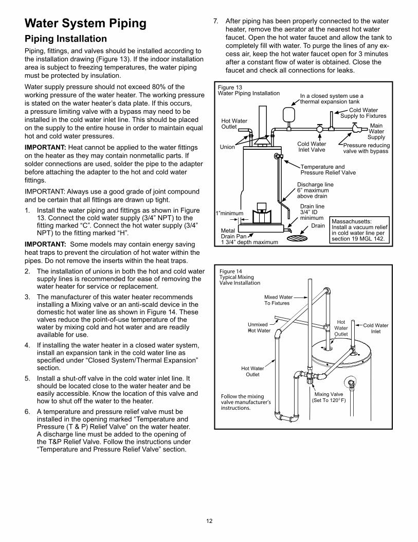
Water System PipingPiping InstallationPiping, fittings, and valves should be installed according to the installation drawing (Figure 13). If the indoor installation area is subject to freezing temperatures, the water piping must be protected by insulation.Water supply pressure should not exceed 80% of the working pressure of the water heater. The working pressure is stated on the water heater’s data plate. If this occurs, a pressure limiting valve with a bypass may need to be installed in the cold water inlet line. This should be placed on the supply to the entire house in order to maintain equal hot and cold water pressures.IMPORTANT: Heat cannot be applied to the water fittings on the heater as they may contain nonmetallic parts. If solder connections are used, solder the pipe to the adapter before attaching the adapter to the hot and cold water fittings.IMPORTANT: Always use a good grade of joint compound and be certain that all fittings are drawn up tight.1. Install the water piping and fittings as shown in Figure
13. Connect the cold water supply (3/4” NPT) to the fitting marked “C”. Connect the hot water supply (3/4” NPT) to the fitting marked “H”.
IMPORTANT: Some models may contain energy saving heat traps to prevent the circulation of hot water within the pipes. Do not remove the inserts within the heat traps.2. The installation of unions in both the hot and cold water
supply lines is recommended for ease of removing the water heater for service or replacement.
3. The manufacturer of this water heater recommends installing a Mixing valve or an anti-scald device in the domestic hot water line as shown in Figure 14. These valves reduce the point-of-use temperature of the water by mixing cold and hot water and are readily available for use.
4. If installing the water heater in a closed water system, install an expansion tank in the cold water line as specified under “Closed System/Thermal Expansion” section.
5. Install a shut-off valve in the cold water inlet line. It should be located close to the water heater and be easily accessible. Know the location of this valve and how to shut off the water to the heater.
6. A temperature and pressure relief valve must be installed in the opening marked “Temperature and Pressure (T & P) Relief Valve” on the water heater. A discharge line must be added to the opening of the T&P Relief Valve. Follow the instructions under “Temperature and Pressure Relief Valve” section.
7. After piping has been properly connected to the water heater, remove the aerator at the nearest hot water faucet. Open the hot water faucet and allow the tank to completely fill with water. To purge the lines of any ex-cess air, keep the hot water faucet open for 3 minutes after a constant flow of water is obtained. Close the faucet and check all connections for leaks.
In a closed system use athermal expansion tank
Figure 13Water Piping Installation
MainWaterSupply
Cold WaterInlet Valve
Cold WaterSupply to Fixtures
Hot WaterOutlet
Union
Temperature andPressure Relief Valve
Discharge line6” maximumabove drain
Drain line3/4” IDminimum
DrainMetalDrain Pan1 3/4” depth maximum
1”minimumMassachusetts: Install a vacuum relief in cold water line per section 19 MGL 142.
Pressure reducingvalve with bypass
Figure 14Typical MixingValve Installation
Follow the mixingvalve manufacturer’sinstructions.
HotWaterOutlet
Mixing Valve(Set To 120 F)0
Hot WaterOutlet
Cold WaterInlet
Mixed WaterTo Fixtures
UnmixedHot Water
13
Please note the following: • The system should be installed only with piping that is
suitable for potable (drinkable) water such as copper, CPVC, or polybutylene. This water heater must not be installed using iron piping or PVC water piping.
• Use only pumps, valves, or fittings that are compatible with potable water.
• Use only full flow ball or gate valves. The use of valves that may cause excessive restriction to water flow is not recommended.
• Use only 95/5 tin-antimony or other equivalent solder. Any lead based solder must not be used.
• Piping that has been treated with chromates, boiler seal, or other chemicals must not be used.
• Chemicals that may contaminate the potable water supply must not be added to the piping system.
Closed System/Thermal Expansion
As water is heated, it expands (thermal expansion). In a closed system, the volume of water will increase. As the volume of water increases, there will be a corresponding increase in water pressure due to thermal expansion. Thermal expansion can cause premature tank failure (leakage). This type of failure is not covered under the limited warranty. Thermal expansion can also cause intermittent temperature-pressure relief valve operation: water discharged from the valve due to excessive pressure build up. The temperature-pressure relief valve is not intended for the constant relief of thermal expansion. This condition is not covered under the limited warranty.
A properly-sized thermal expansion tank should be installed on all closed systems to control the harmful effects of thermal expansion. Contact a plumbing service agency or your retail supplier regarding the installation of a thermal expansion leak.
Explosion Hazard
If the temperature and pressure relief valve is dripping or leaking, have a qualified person replace it.
Examples of a qualified person include:licensed plumbers, authorized gas company personnel, and authorized service personnel.
Do not plug valve.
Do not remove valve.
Failure to follow these instructions can result in death, or explosion.
WARNING
14
Temperature and Pressure Relief Valve
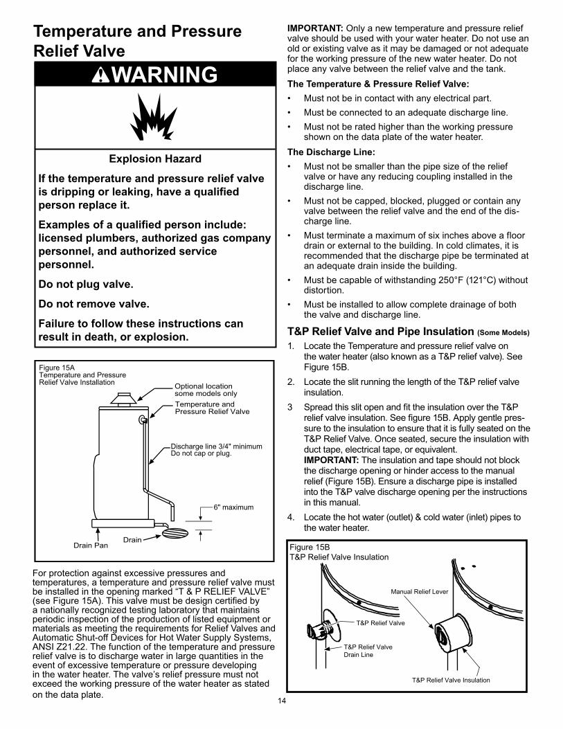
For protection against excessive pressures and temperatures, a temperature and pressure relief valve must be installed in the opening marked “T & P RELIEF VALVE” (see Figure 15A). This valve must be design certified by a nationally recognized testing laboratory that maintains periodic inspection of the production of listed equipment or materials as meeting the requirements for Relief Valves and Automatic Shut-off Devices for Hot Water Supply Systems, ANSI Z21.22. The function of the temperature and pressure relief valve is to discharge water in large quantities in the event of excessive temperature or pressure developing in the water heater. The valve’s relief pressure must not exceed the working pressure of the water heater as stated on the data plate.
IMPORTANT: Only a new temperature and pressure relief valve should be used with your water heater. Do not use an old or existing valve as it may be damaged or not adequate for the working pressure of the new water heater. Do not place any valve between the relief valve and the tank.The Temperature & Pressure Relief Valve:• Must not be in contact with any electrical part.• Must be connected to an adequate discharge line.• Must not be rated higher than the working pressure
shown on the data plate of the water heater.The Discharge Line: • Must not be smaller than the pipe size of the relief
valve or have any reducing coupling installed in the discharge line.
• Must not be capped, blocked, plugged or contain any valve between the relief valve and the end of the dis-charge line.
• Must terminate a maximum of six inches above a floor drain or external to the building. In cold climates, it is recommended that the discharge pipe be terminated at an adequate drain inside the building.
• Must be capable of withstanding 250°F (121°C) without distortion.
• Must be installed to allow complete drainage of both the valve and discharge line.
T&P Relief Valve and Pipe Insulation (Some Models)
1. Locate the Temperature and pressure relief valve on the water heater (also known as a T&P relief valve). See Figure 15B.
2. Locate the slit running the length of the T&P relief valve insulation.
3 Spread this slit open and fit the insulation over the T&P relief valve insulation. See figure 15B. Apply gentle pres-sure to the insulation to ensure that it is fully seated on the T&P Relief Valve. Once seated, secure the insulation with duct tape, electrical tape, or equivalent.IMPORTANT: The insulation and tape should not block the discharge opening or hinder access to the manual relief (Figure 15B). Ensure a discharge pipe is installed into the T&P valve discharge opening per the instructions in this manual.
4. Locate the hot water (outlet) & cold water (inlet) pipes to the water heater.
Figure 15ATemperature and PressureRelief Valve Installation
Discharge line 3/4" minimumDo not cap or plug.
6" maximum
Figure 15B T&P Relief Valve Insulation
T&P Relief Valve Insulation
Manual Relief Lever
T&P Relief Valve
T&P Relief ValveDrain Line
Explosion Hazard
If the temperature and pressure relief valve is dripping or leaking, have a qualified person replace it.
Examples of a qualified person include:licensed plumbers, authorized gas company personnel, and authorized service personnel.
Do not plug valve.
Do not remove valve.
Failure to follow these instructions can result in death, or explosion.
WARNING
15
5. Locate the slit running the length of a section of pipe insulation.
6. Spread the slit open and slip the insulation over the cold water (inlet) pipe. Apply gentle pressure along the length of the insulation to ensure that it is fully seated around the pipe. Also, ensure that the base of the insulation is flush with the water heater. Once seated, secure the insulation with duct tape, electrical tape, or equivalent.
7. Repeat steps 5 through 6 for the hot water (outlet) pipe.8. Add additional sections of pipe insulation as needed.
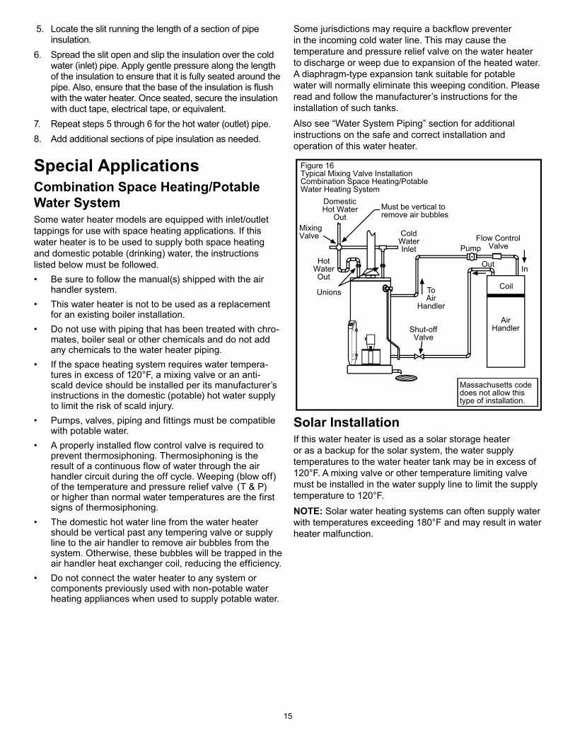
Special ApplicationsCombination Space Heating/Potable Water SystemSome water heater models are equipped with inlet/outlet tappings for use with space heating applications. If this water heater is to be used to supply both space heating and domestic potable (drinking) water, the instructions listed below must be followed.• Be sure to follow the manual(s) shipped with the air
handler system.• This water heater is not to be used as a replacement
for an existing boiler installation.• Do not use with piping that has been treated with chro-
mates, boiler seal or other chemicals and do not add any chemicals to the water heater piping.
• If the space heating system requires water tempera-tures in excess of 120°F, a mixing valve or an anti-scald device should be installed per its manufacturer’s instructions in the domestic (potable) hot water supply to limit the risk of scald injury.
• Pumps, valves, piping and fittings must be compatible with potable water.
• A properly installed flow control valve is required to prevent thermosiphoning. Thermosiphoning is the result of a continuous flow of water through the air handler circuit during the off cycle. Weeping (blow off) of the temperature and pressure relief valve (T & P) or higher than normal water temperatures are the first signs of thermosiphoning.
• The domestic hot water line from the water heater should be vertical past any tempering valve or supply line to the air handler to remove air bubbles from the system. Otherwise, these bubbles will be trapped in the air handler heat exchanger coil, reducing the efficiency.
• Do not connect the water heater to any system or components previously used with non-potable water heating appliances when used to supply potable water.
Some jurisdictions may require a backflow preventer in the incoming cold water line. This may cause the temperature and pressure relief valve on the water heater to discharge or weep due to expansion of the heated water. A diaphragm-type expansion tank suitable for potable water will normally eliminate this weeping condition. Please read and follow the manufacturer’s instructions for the installation of such tanks.Also see “Water System Piping” section for additional instructions on the safe and correct installation and operation of this water heater.
Coil
Must be vertical toremove air bubbles
Figure 16Typical Mixing Valve InstallationCombination Space Heating/PotableWater Heating System
DomesticHot Water
OutMixingValve
HotWaterOut
Unions
ColdWaterInlet Pump
Flow ControlValve
ToAir
Handler
Out In
AirHandlerShut-off
Valve
Massachusetts code does not allow this type of installation.
Solar InstallationIf this water heater is used as a solar storage heater or as a backup for the solar system, the water supply temperatures to the water heater tank may be in excess of 120°F. A mixing valve or other temperature limiting valve must be installed in the water supply line to limit the supply temperature to 120°F.NOTE: Solar water heating systems can often supply water with temperatures exceeding 180°F and may result in water heater malfunction.
16
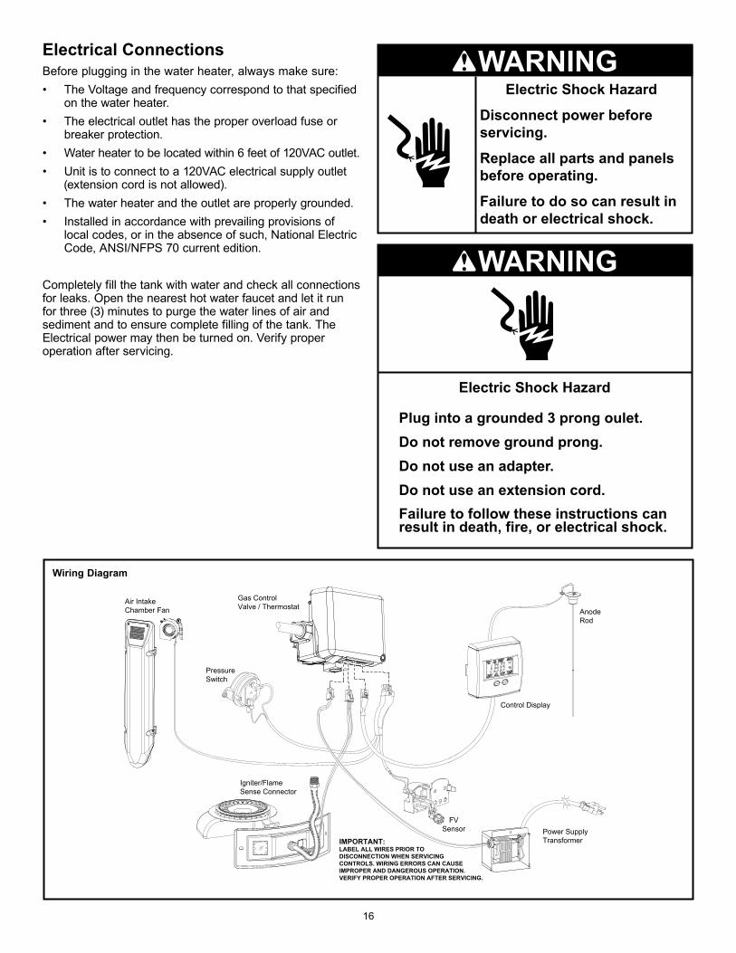
WARNINGElectric Shock Hazard
Disconnect power before servicing.
Replace all parts and panels before operating.
Failure to do so can result indeath or electrical shock.
Pressure Switch
Control Display
Power SupplyTransformer
Igniter/FlameSense Connector
Air IntakeChamber Fan Anode
Rod
Gas Control Valve / Thermostat
IMPORTANT:LABEL ALL WIRES PRIOR TO DISCONNECTION WHEN SERVICING CONTROLS. WIRING ERRORS CAN CAUSE IMPROPER AND DANGEROUS OPERATION. VERIFY PROPER OPERATION AFTER SERVICING.
FVSensor
Wiring Diagram
Electrical ConnectionsBefore plugging in the water heater, always make sure:• The Voltage and frequency correspond to that specified on the water heater.• The electrical outlet has the proper overload fuse or breaker protection.• Water heater to be located within 6 feet of 120VAC outlet. • Unit is to connect to a 120VAC electrical supply outlet (extension cord is not allowed).• The water heater and the outlet are properly grounded.• Installed in accordance with prevailing provisions of local codes, or in the absence of such, National Electric Code, ANSI/NFPS 70 current edition.
Completely fill the tank with water and check all connections for leaks. Open the nearest hot water faucet and let it run for three (3) minutes to purge the water lines of air and sediment and to ensure complete filling of the tank. The Electrical power may then be turned on. Verify proper operation after servicing.
WARNING
17
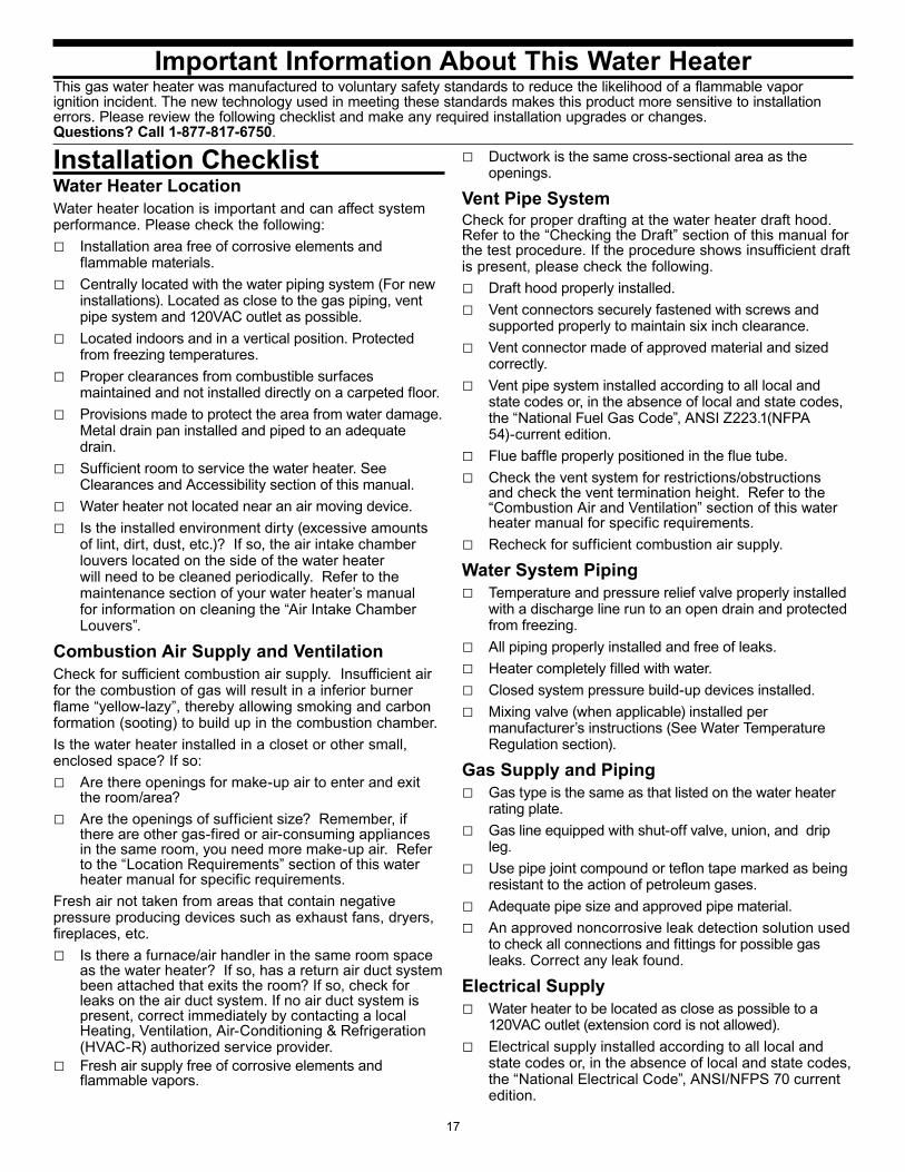
Water Heater LocationWater heater location is important and can affect system performance. Please check the following:□ Installation area free of corrosive elements and
flammable materials.□ Centrally located with the water piping system (For new
installations). Located as close to the gas piping, vent pipe system and 120VAC outlet as possible.
□ Located indoors and in a vertical position. Protected from freezing temperatures.
□ Proper clearances from combustible surfaces maintained and not installed directly on a carpeted floor.
□ Provisions made to protect the area from water damage. Metal drain pan installed and piped to an adequate drain.
□ Sufficient room to service the water heater. See Clearances and Accessibility section of this manual.
□ Water heater not located near an air moving device.□ Is the installed environment dirty (excessive amounts
of lint, dirt, dust, etc.)? If so, the air intake chamber louvers located on the side of the water heater will need to be cleaned periodically. Refer to the maintenance section of your water heater’s manual for information on cleaning the “Air Intake Chamber Louvers”.
Combustion Air Supply and VentilationCheck for sufficient combustion air supply. Insufficient air for the combustion of gas will result in a inferior burner flame “yellow-lazy”, thereby allowing smoking and carbon formation (sooting) to build up in the combustion chamber.Is the water heater installed in a closet or other small, enclosed space? If so:□ Are there openings for make-up air to enter and exit
the room/area? □ Are the openings of sufficient size? Remember, if
there are other gas-fired or air-consuming appliances in the same room, you need more make-up air. Refer to the “Location Requirements” section of this water heater manual for specific requirements.
Fresh air not taken from areas that contain negative pressure producing devices such as exhaust fans, dryers, fireplaces, etc.□ Is there a furnace/air handler in the same room space
as the water heater? If so, has a return air duct system been attached that exits the room? If so, check for leaks on the air duct system. If no air duct system is present, correct immediately by contacting a local Heating, Ventilation, Air-Conditioning & Refrigeration (HVAC-R) authorized service provider.
□ Fresh air supply free of corrosive elements and flammable vapors.
□ Ductwork is the same cross-sectional area as the openings.
Vent Pipe SystemCheck for proper drafting at the water heater draft hood. Refer to the “Checking the Draft” section of this manual for the test procedure. If the procedure shows insufficient draft is present, please check the following.□ Draft hood properly installed.□ Vent connectors securely fastened with screws and
supported properly to maintain six inch clearance.□ Vent connector made of approved material and sized
correctly.□ Vent pipe system installed according to all local and
state codes or, in the absence of local and state codes, the “National Fuel Gas Code”, ANSI Z223.1(NFPA 54)-current edition.
□ Flue baffle properly positioned in the flue tube.□ Check the vent system for restrictions/obstructions
and check the vent termination height. Refer to the “Combustion Air and Ventilation” section of this water heater manual for specific requirements.
□ Recheck for sufficient combustion air supply.
Water System Piping□ Temperature and pressure relief valve properly installed
with a discharge line run to an open drain and protected from freezing.
□ All piping properly installed and free of leaks.□ Heater completely filled with water.□ Closed system pressure build-up devices installed.□ Mixing valve (when applicable) installed per
manufacturer’s instructions (See Water Temperature Regulation section).
Gas Supply and Piping□ Gas type is the same as that listed on the water heater
rating plate.□ Gas line equipped with shut-off valve, union, and drip
leg.□ Use pipe joint compound or teflon tape marked as being
resistant to the action of petroleum gases.□ Adequate pipe size and approved pipe material.□ An approved noncorrosive leak detection solution used
to check all connections and fittings for possible gas leaks. Correct any leak found.
Electrical Supply□ Water heater to be located as close as possible to a
120VAC outlet (extension cord is not allowed).□ Electrical supply installed according to all local and
state codes or, in the absence of local and state codes, the “National Electrical Code”, ANSI/NFPS 70 current edition.
Important Information About This Water HeaterThis gas water heater was manufactured to voluntary safety standards to reduce the likelihood of a flammable vapor ignition incident. The new technology used in meeting these standards makes this product more sensitive to installation errors. Please review the following checklist and make any required installation upgrades or changes. Questions? Call 1-877-817-6750.
Installation Checklist
18
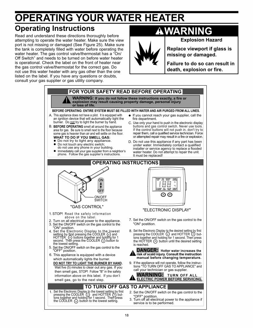
OPERATING YOUR WATER HEATEROperating InstructionsRead and understand these directions thoroughly before attempting to operate the water heater. Make sure the view port is not missing or damaged (See Figure 25). Make sure the tank is completely filled with water before operating the water heater. The gas control valve/thermostat has a “On/Off Switch” and needs to be turned on before water heater is operational. Check the label on the front of heater near the gas control valve/thermostat for the correct gas. Do not use this water heater with any gas other than the one listed on the label. If you have any questions or doubts, consult your gas supplier or gas utility company.
Explosion Hazard
Replace viewport if glass is missing or damaged.
Failure to do so can result in death, explosion or fire.
WARNING
Wait five (5) minutes to clear out any gas. If youthen smell gas, STOP! Follow "B" in the safetyinformation above on this label. If you don’tsmell gas, go to the next step.
Set the Electronic Display to the lowest setting by firstpressing the COOLER and HOTTER but-tons together and holding for 1 second. Then pressthe COOLER button to the lowest setting.
185741-000
BEFORE OPERATING: ENTIRE SYSTEM MUST BE FILLED WITH WATER AND AIR PURGED FROM ALL LINES.A.
B.C.
D.WHAT TO DO IF YOU SMELL GAS:
Do not try to light any appliance.
Immediately call your gas supplier from a neighbor’sphone. Follow the gas supplier’s instructions.
If you cannot reach your gas supplier, call thefire department.
Do not touch any electric switch;do not use any phone in your building.
1.
1. STOP! R e a d t h e s a f e t y i n f o r m a t i o n above on t he l abe l .
3. Set the ON/OFF switch on the gas control to the"ON" position.
5. Set the ON/OFF switch on the gas control to the"OFF" position. DANGER: Hotter water increases the
risk of scald injury. Consult the instructionmanual before changing temperature.
WARNING: If you do not follow these instructions exactly, a fire orexplosion may result causing property damage, personal injuryor loss of life.
Turn on all electrical power to the appliance.2.
Turn off all electrical power to the appliance ifservice is to be performed.
3.
Set the ON/OFF switch on the gas control to the"ON" postition.
7.
Set the ON/OFF switch on the gas control to the"OFF" postition.
2.
6. This appliance is equipped with a devicewhich automatically lights the burner.DO NOT TRY TO LIGHT THE BURNER BY HAND.
This appliance does not have a pilot. It is equipped withan ignition device that will automatically light the burner. Do not try to light the burner by hand.BEFORE OPERATING smell all around the appliancearea for gas. Be sure to smell next to the floor becausesome gas is heavier than air and will settle on the floor.
Use only your hand to push in the electronic displaybuttons and gas control switch. Never use tools.If the control buttons will not push in, don't try torepair them, call a qualified service technician. Forceor attempted repair may result in a fire or explosion.Do not use this appliance if any part has beenunder water. Immediately contact a qualifiedinstaller or service agency to replace a floodedwater heater. Do not attempt to repair the unit.It must be replaced!
Set the Electronic Display to the desired setting by firstpressing the COOLER and HOTTER but-tons together and holding for 1 second. Then pressthe HOTTER button until the desired settingis reached.
8.Set the Electronic Display to the lowestsetting by first pressing the COOLER andHOTTER buttons together and holding for 1second. Then press the COOLER button tothe lowest setting.
4.
FOR YOUR SAFETY READ BEFORE OPERATING
OPERATING INSTRUCTIONS
TO TURN OFF GAS TO APPLIANCE
"ELECTRONIC DISPLAY""GAS CONTROL"
ON/OFF SWITCH
ON
OFF
WARNING: TURN OFF ALL ELECTRIC POWER BEFORE SERVICING.
9. If the appliance will not operate, follow the instruc-tions "TO TURN OFF GAS TO APPLIANCE" andcall your technician or gas supplier.
19
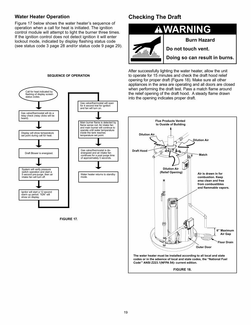
FIGURE 17.
SEQUENCE OF OPERATION
System will verify pressure switch operation and start a 5 second pre-purge, then air intake fan will turn off.
Ignitor will start a 12 second warm up period. “IGN” will show on display.
Gas valve/thermostat is de- energized and air intake fan continues for a post purge time of approximately 5 seconds.
Water heater returns to standby mode.
Main burner flame is detected by flame sense rod. Air intake fan and main burner will continue to operate until water temperature inside the tank reaches temperature set point.
Gas valve/thermostat will do a relay check (relay clicks will be heard).
Display will show temperature set point during call for heat.
Gas valve/thermostat will open for 4 second trial for ignition and fan will turn on.
Call for heat indicated by flashing of display screen status codes.
Flue Products Vented to Ouside of Building
Draft Hood
Dilution Air
Air is drawn in forcombustion. Keep area clean and free from combustibles and flammable vapors.
The water heater must be installed according to all local and state codes or in the adsence of local and state codes, the “National Fuel Code”’ ANSI Z223.1(NFPA 54)- current edition.
Dilution Air (Relief Opening)
Dilution Air
Match
Outer DoorFloor Drain
6” Maximum Air Gap
FIGURE 18.
Draft Blower is energized.
Checking The Draft
After successfully lighting the water heater, allow the unit to operate for 15 minutes and check the draft hood relief opening for proper draft (Figure 18). Make sure all other appliances in the area are operating and all doors are closed when performing the draft test. Pass a match flame around the relief opening of the draft hood. A steady flame drawn into the opening indicates proper draft.
Burn Hazard
Do not touch vent.
Doing so can result in burns.
WARNINGWater Heater OperationFigure 17 below shows the water heater’s sequence of operation when a call for heat is initiated. The ignition control module will attempt to light the burner three times. If the ignition control does not detect ignition it will enter lockout mode, indicated by display flashing status code (see status code 3 page 28 and/or status code 9 page 29).
20
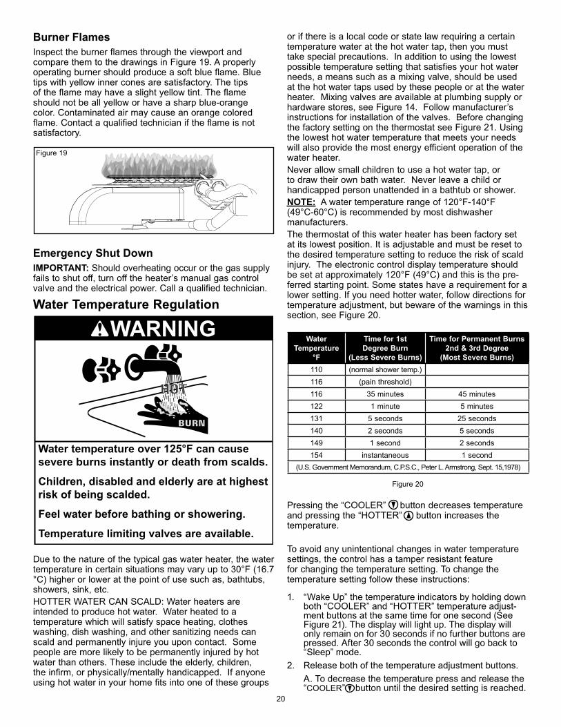
Burner FlamesInspect the burner flames through the viewport and compare them to the drawings in Figure 19. A properly operating burner should produce a soft blue flame. Blue tips with yellow inner cones are satisfactory. The tips of the flame may have a slight yellow tint. The flame should not be all yellow or have a sharp blue-orange color. Contaminated air may cause an orange colored flame. Contact a qualified technician if the flame is not satisfactory.
Emergency Shut DownIMPORTANT: Should overheating occur or the gas supply fails to shut off, turn off the heater’s manual gas control valve and the electrical power. Call a qualified technician.
Water Temperature Regulation
Water temperature over 125°F can cause severe burns instantly or death from scalds.
Children, disabled and elderly are at highest risk of being scalded.
Feel water before bathing or showering.
Temperature limiting valves are available.
WARNING
Due to the nature of the typical gas water heater, the water temperature in certain situations may vary up to 30°F (16.7 °C) higher or lower at the point of use such as, bathtubs, showers, sink, etc. HOTTER WATER CAN SCALD: Water heaters are intended to produce hot water. Water heated to a temperature which will satisfy space heating, clothes washing, dish washing, and other sanitizing needs can scald and permanently injure you upon contact. Some people are more likely to be permanently injured by hot water than others. These include the elderly, children, the infirm, or physically/mentally handicapped. If anyone using hot water in your home fits into one of these groups
or if there is a local code or state law requiring a certain temperature water at the hot water tap, then you must take special precautions. In addition to using the lowest possible temperature setting that satisfies your hot water needs, a means such as a mixing valve, should be used at the hot water taps used by these people or at the water heater. Mixing valves are available at plumbing supply or hardware stores, see Figure 14. Follow manufacturer’s instructions for installation of the valves. Before changing the factory setting on the thermostat see Figure 21. Using the lowest hot water temperature that meets your needs will also provide the most energy efficient operation of the water heater.Never allow small children to use a hot water tap, or to draw their own bath water. Never leave a child or handicapped person unattended in a bathtub or shower. NOTE: A water temperature range of 120°F-140°F (49°C-60°C) is recommended by most dishwasher manufacturers.The thermostat of this water heater has been factory set at its lowest position. It is adjustable and must be reset to the desired temperature setting to reduce the risk of scald injury. The electronic control display temperature should be set at approximately 120°F (49°C) and this is the pre-ferred starting point. Some states have a requirement for a lower setting. If you need hotter water, follow directions for temperature adjustment, but beware of the warnings in this section, see Figure 20.
Figure 20
Pressing the “COOLER” button decreases temperature and pressing the “HOTTER” button increases the temperature.
To avoid any unintentional changes in water temperature settings, the control has a tamper resistant feature for changing the temperature setting. To change the temperature setting follow these instructions:
1. “Wake Up” the temperature indicators by holding down both “COOLER” and “HOTTER” temperature adjust-ment buttons at the same time for one second (See Figure 21). The display will light up. The display will only remain on for 30 seconds if no further buttons are pressed. After 30 seconds the control will go back to “Sleep” mode.
2. Release both of the temperature adjustment buttons. A. To decrease the temperature press and release the
“COOLER” button until the desired setting is reached.
Figure 19
Water Temperature
°F
Time for 1st Degree Burn
(Less Severe Burns)
Time for Permanent Burns 2nd & 3rd Degree
(Most Severe Burns)110 (normal shower temp.)116 (pain threshold)116 35 minutes 45 minutes122 1 minute 5 minutes131 5 seconds 25 seconds140 2 seconds 5 seconds149 1 second 2 seconds154 instantaneous 1 second
(U.S. Government Memorandum, C.P.S.C., Peter L. Armstrong, Sept. 15,1978)
21
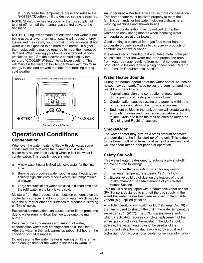
B. To increase the temperature press and release the “HOTTER” button until the desired setting is reached.
NOTE: Should overheating occur or the gas supply fail to shut off, turn off the manual gas control valve to the appliance.
NOTE: During low demand periods when hot water is not being used, a lower thermostat setting will reduce energy losses and may satisfy your normal hot water needs. If hot water use is expected to be more than normal, a higher thermostat setting may be required to meet the increased demand. When leaving your home for extended periods (vacations, etc.) Set the electronic control display tem-perature “COOLER” button to its lowest setting. This will maintain the water at low temperatures with minimum energy losses and prevent the tank from freezing during cold weather.
Operational Conditions CondensationWhenever the water heater is filled with cold water, some condensate will form while the burner is on. A water heater may appear to be leaking when in fact the water is condensation. This usually happens when:
a. A new water heater is filled with cold water for the first time.
b. Burning gas produces water vapor in water heaters, par-ticularly high efficiency models where flue temperatures are lower.
c. Large amounts of hot water are used in a short time and the refill water in the tank is very cold.
Moisture from the products of combustion condense on the cooler tank surfaces and form drops of water which may fall onto the burner or other hot surfaces to produce a “sizzling” or “frying” noise. Excessive condensation can cause burner flame problems due to water running down the flue tube onto the main burner. Because of the suddenness and amount of water, condensation water may be diagnosed as a “tank leak”. After the water in the tank warms up (about 1-2 hours), the condition should disappear. Do not assume the water heater is leaking until there has been enough time for the water in the tank to warm up.
Gas Control Valve/Thermostat Settings
COOLERHOTTER
Electronic Control Display
Figure 21
An undersized water heater will cause more condensation. The water heater must be sized properly to meet the family’s demands for hot water including dishwashers, washing machines and shower heads. Excessive condensation may be noticed during the winter and early spring months when incoming water temperatures are at their lowest. Good venting is essential for a gas fired water heater to operate properly as well as to carry away products of combustion and water vapor. It is always recommended that a suitable metal drain pan be installed under the water heater to protect the area from water damage resulting from normal condensation production, a leaking tank or piping connections. Refer to the “Location Requirements” section.
Water Heater SoundsDuring the normal operation of the water heater, sounds or noises may be heard. These noises are common and may result from the following:1. Normal expansion and contraction of metal parts
during periods of heat-up and cool-down.2. Condensation causes sizzling and popping within the
burner area and should be considered normal.3. Sediment buildup in the tank bottom will create varying
amounts of noise and may cause premature tank failure. Drain and flush the tank as directed under the “Draining and Flushing” section.
Smoke/OdorThe water heater may give off a small amount of smoke and odor during the initial start-up of the unit. This is due to the burning off of oil from metal parts of a new unit and will disappear after a brief period of operation.
Safety Shut-offThis water heater is designed to automatically shut-off in the event of the following:1. The burner flame is extinguished for any reason.2. The water temperature exceeds 195°F (91°C).3. Excessive build up of dust on the louvers of the air
intake chamber. See Maintenance of your Water Heater Section.
This unit is also equipped with a flammable vapor sensor (FV Sensor), designed to shut off the gas supply in the event the water heater has been exposed to flammable vapors (e.g., spilled gasoline). A high temperature limit switch or ECO (Energy Cut Off) in the tank is used to shut off the unit if the water temperature exceeds 195°F (91°C). The ECO is a single-use switch, which, if activated, requires complete replacement of the entire gas control valve/thermostat. If the ECO should activate, the water heater cannot be used until the gas control valve/thermostat is replaced by a qualified technician. Contact your local dealer for service information.
22
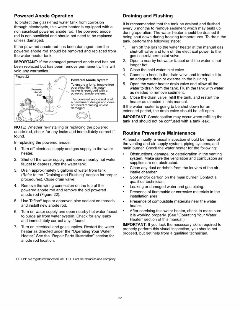
Powered Anode OperationTo protect the glass-lined water tank from corrosion through electrolysis, this water heater is equipped with a non sacrificial powered anode rod. The powered anode rod is non sacrificial and should not need to be replaced unless damaged.If the powered anode rod has been damaged then the powered anode rod should be removed and replaced from the water heater tank. IMPORTANT: If the damaged powered anode rod has not been replaced but has been remove permanently, this will void any warranties.
NOTE: Whether re-installing or replacing the powered anode rod, check for any leaks and immediately correct if found.In replacing the powered anode:1. Turn off electrical supply and gas supply to the water
heater.2. Shut off the water supply and open a nearby hot water
faucet to depressurize the water tank.3. Drain approximately 5 gallons of water from tank
(Refer to the “Draining and Flushing” section for proper procedures). Close drain valve.
4. Remove the wiring connection on the top of the powered anode rod and remove the old powered anode rod (Figure 22).
5. Use Teflon® tape or approved pipe sealant on threads and install new anode rod.
6. Turn on water supply and open nearby hot water faucet to purge air from water system. Check for any leaks and immediately correct any if found.
7. Turn on electrical and gas supplies. Restart the water heater as directed under the “Operating Your Water Heater.” See the “Repair Parts Illustration” section for anode rod location.
TEFLON® is a registered trademark of E.I. Du Pont De Nemours and Company
Draining and FlushingIt is recommended that the tank be drained and flushed every 6 months to remove sediment which may build up during operation. The water heater should be drained if being shut down during freezing temperatures. To drain the tank, perform the following steps:1. Turn off the gas to the water heater at the manual gas
shut-off valve and turn off the electrical power to the gas control/thermostat valve.
2. Open a nearby hot water faucet until the water is not longer hot.
3. Close the cold water inlet valve.4. Connect a hose to the drain valve and terminate it to
an adequate drain or external to the building.5. Open the water heater drain valve and allow all the
water to drain from the tank. Flush the tank with water as needed to remove sediment.
6. Close the drain valve, refill the tank, and restart the heater as directed in this manual.
If the water heater is going to be shut down for an extended period, the drain valve should be left open.IMPORTANT: Condensation may occur when refilling the tank and should not be confused with a tank leak.
Routine Preventive MaintenanceAt least annually, a visual inspection should be made of the venting and air supply system, piping systems, and main burner. Check the water heater for the following:• Obstructions, damage, or deterioration in the venting
system. Make sure the ventilation and combustion air supplies are not obstructed.
• Clean any dust or debris from the louvers of the air intake chamber.
• Soot and/or carbon on the main burner. Contact a qualified technician.
• Leaking or damaged water and gas piping.• Presence of flammable or corrosive materials in the
installation area.• Presence of combustible materials near the water
heater.• After servicing this water heater, check to make sure
it is working properly. (See “Operating Your Water Heater” section of this manual.)
IMPORTANT: If you lack the necessary skills required to properly perform this visual inspection, you should not proceed, but get help from a qualified technician.
PoweredAnode
Rod
Powered Anode SystemTo ensure a long, trouble-freeoperating life, this water heater is equipped with a powered anode system.
The powered anode rod is of a permanent design and does not need replacing unless damaged.
Figure 22
23
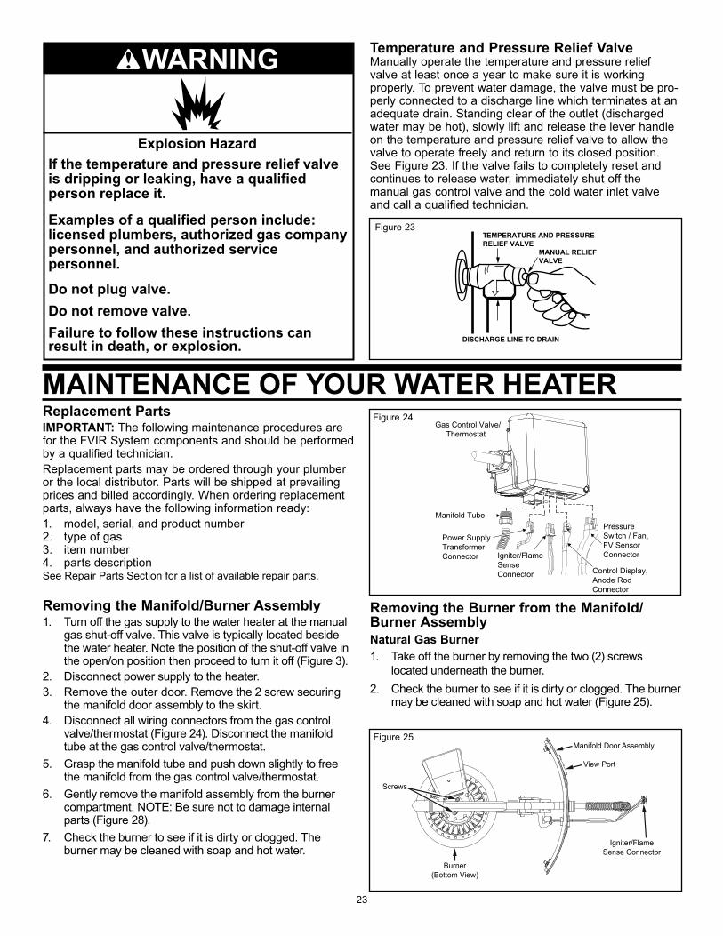
Temperature and Pressure Relief Valve Manually operate the temperature and pressure relief valve at least once a year to make sure it is working properly. To prevent water damage, the valve must be pro- perly connected to a discharge line which terminates at an adequate drain. Standing clear of the outlet (discharged water may be hot), slowly lift and release the lever handle on the temperature and pressure relief valve to allow the valve to operate freely and return to its closed position. See Figure 23. If the valve fails to completely reset and continues to release water, immediately shut off the manual gas control valve and the cold water inlet valve and call a qualified technician.
TEMPERATURE AND PRESSURERELIEF VALVE
DISCHARGE LINE TO DRAIN
MANUAL RELIEFVALVE
Removing the Burner from the Manifold/Burner AssemblyNatural Gas Burner1. Take off the burner by removing the two (2) screws
located underneath the burner.2. Check the burner to see if it is dirty or clogged. The burner
may be cleaned with soap and hot water (Figure 25).
Replacement PartsIMPORTANT: The following maintenance procedures are for the FVIR System components and should be performed by a qualified technician.Replacement parts may be ordered through your plumber or the local distributor. Parts will be shipped at prevailing prices and billed accordingly. When ordering replacement parts, always have the following information ready:1. model, serial, and product number2. type of gas3. item number4. parts descriptionSee Repair Parts Section for a list of available repair parts.
Removing the Manifold/Burner Assembly1. Turn off the gas supply to the water heater at the manual
gas shut-off valve. This valve is typically located beside the water heater. Note the position of the shut-off valve in the open/on position then proceed to turn it off (Figure 3).
2. Disconnect power supply to the heater.3. Remove the outer door. Remove the 2 screw securing
the manifold door assembly to the skirt.4. Disconnect all wiring connectors from the gas control
valve/thermostat (Figure 24). Disconnect the manifold tube at the gas control valve/thermostat.
5. Grasp the manifold tube and push down slightly to free the manifold from the gas control valve/thermostat.
6. Gently remove the manifold assembly from the burner compartment. NOTE: Be sure not to damage internal parts (Figure 28).
7. Check the burner to see if it is dirty or clogged. The burner may be cleaned with soap and hot water.
MAINTENANCE OF YOUR WATER HEATER
Manifold Tube
Control Display, Anode RodConnector
PressureSwitch / Fan,FV SensorConnector
Power SupplyTransformerConnector Igniter/Flame
SenseConnector
Gas Control Valve/ Thermostat
Figure 24
Burner(Bottom View)
Screws
Manifold Door Assembly
Igniter/FlameSense Connector
View Port
Figure 25
Figure 23
Explosion HazardIf the temperature and pressure relief valve is dripping or leaking, have a qualified person replace it.
Examples of a qualified person include:licensed plumbers, authorized gas company personnel, and authorized service personnel.
Do not plug valve.Do not remove valve.Failure to follow these instructions can result in death, or explosion.
WARNING
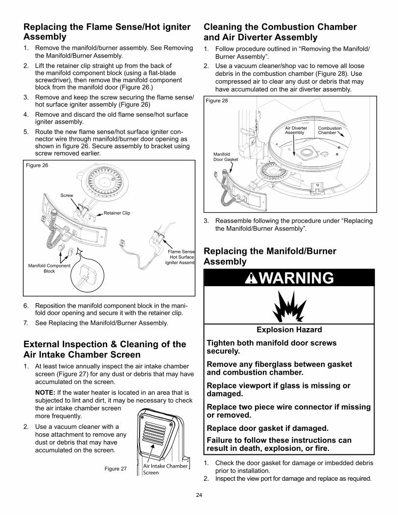
24
Replacing the Flame Sense/Hot igniter Assembly1. Remove the manifold/burner assembly. See Removing
the Manifold/Burner Assembly.2. Lift the retainer clip straight up from the back of
the manifold component block (using a flat-blade screwdriver), then remove the manifold component block from the manifold door (Figure 26.)
3. Remove and keep the screw securing the flame sense/hot surface igniter assembly (Figure 26)
4. Remove and discard the old flame sense/hot surface igniter assembly.
5. Route the new flame sense/hot surface igniter con-nector wire through manifold/burner door opening as shown in figure 26. Secure assembly to bracket using screw removed earlier.
6. Reposition the manifold component block in the mani-fold door opening and secure it with the retainer clip.
7. See Replacing the Manifold/Burner Assembly.
External Inspection & Cleaning of the Air Intake Chamber Screen1. At least twice annually inspect the air intake chamber
screen (Figure 27) for any dust or debris that may have accumulated on the screen.
NOTE: If the water heater is located in an area that is subjected to lint and dirt, it may be necessary to check the air intake chamber screen more frequently.
2. Use a vacuum cleaner with a hose attachment to remove any dust or debris that may have accumulated on the screen.
Cleaning the Combustion Chamber and Air Diverter Assembly1. Follow procedure outlined in “Removing the Manifold/
Burner Assembly”.2. Use a vacuum cleaner/shop vac to remove all loose
debris in the combustion chamber (Figure 28). Use compressed air to clear any dust or debris that may have accumulated on the air diverter assembly.
Air DiverterAssembly
CombustionChamber
ManifoldDoor Gasket
3. Reassemble following the procedure under “Replacing the Manifold/Burner Assembly”.
Replacing the Manifold/Burner Assembly
Screw
Retainer Clip
Manifold ComponentBlock
Flame Sense/Hot Surface
Igniter Assemb
Air Intake Chamber Screen
Figure 27
Figure 26
Figure 28
Explosion HazardTighten both manifold door screws securely.
Remove any fiberglass between gasketand combustion chamber.
Replace viewport if glass is missing ordamaged.Replace two piece wire connector if missing or removed.Replace door gasket if damaged.Failure to follow these instructions can result in death, explosion, or fire.
WARNING
1. Check the door gasket for damage or imbedded debris prior to installation.
2. Inspect the view port for damage and replace as required.
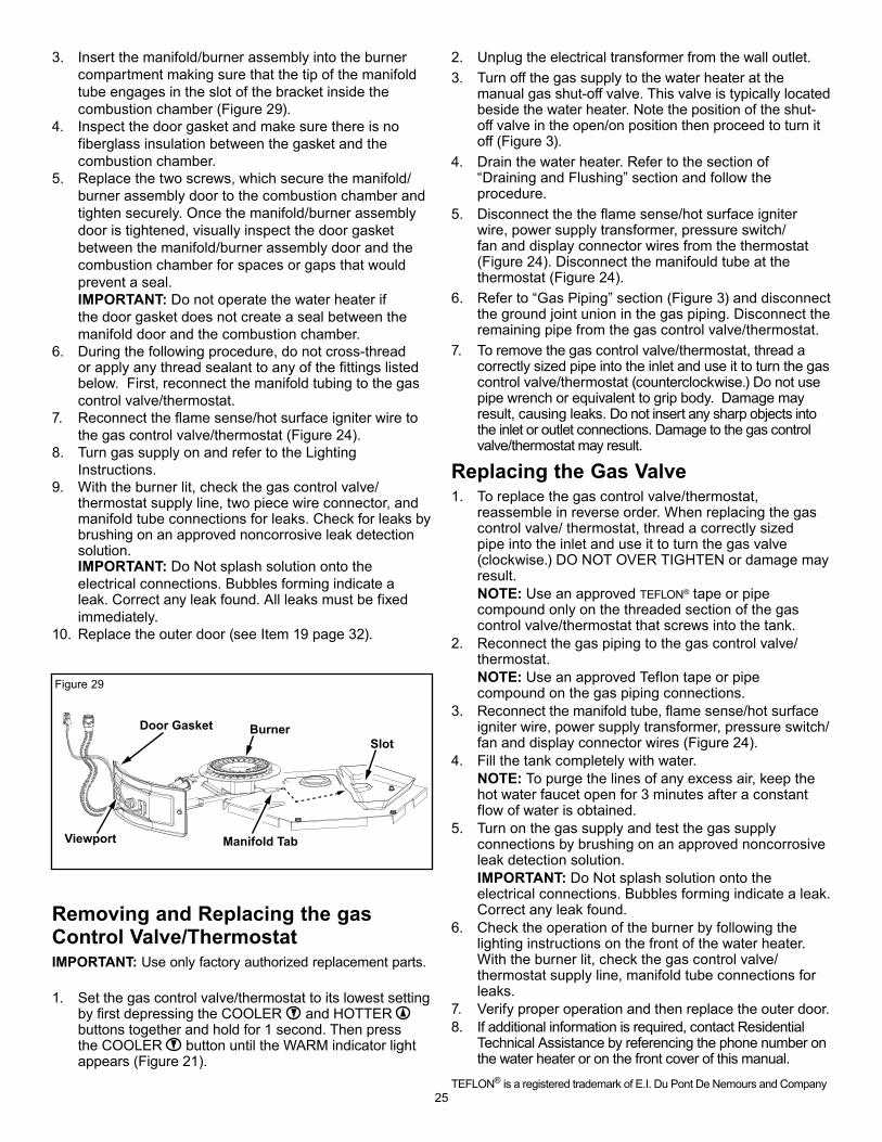
25
3. Insert the manifold/burner assembly into the burner compartment making sure that the tip of the manifold tube engages in the slot of the bracket inside the combustion chamber (Figure 29).
4. Inspect the door gasket and make sure there is no fiberglass insulation between the gasket and the combustion chamber.
5. Replace the two screws, which secure the manifold/burner assembly door to the combustion chamber and tighten securely. Once the manifold/burner assembly door is tightened, visually inspect the door gasket between the manifold/burner assembly door and the combustion chamber for spaces or gaps that would prevent a seal.
IMPORTANT: Do not operate the water heater if the door gasket does not create a seal between the manifold door and the combustion chamber.
6. During the following procedure, do not cross-thread or apply any thread sealant to any of the fittings listed below. First, reconnect the manifold tubing to the gas control valve/thermostat.
7. Reconnect the flame sense/hot surface igniter wire to the gas control valve/thermostat (Figure 24).
8. Turn gas supply on and refer to the Lighting Instructions.
9. With the burner lit, check the gas control valve/thermostat supply line, two piece wire connector, and manifold tube connections for leaks. Check for leaks by brushing on an approved noncorrosive leak detection solution.
IMPORTANT: Do Not splash solution onto the electrical connections. Bubbles forming indicate a leak. Correct any leak found. All leaks must be fixed immediately.
10. Replace the outer door (see Item 19 page 32).
Door Gasket
Viewport Manifold Tab
SlotBurner
Removing and Replacing the gas Control Valve/ThermostatIMPORTANT: Use only factory authorized replacement parts.
1. Set the gas control valve/thermostat to its lowest setting by first depressing the COOLER and HOTTER buttons together and hold for 1 second. Then press the COOLER button until the WARM indicator light appears (Figure 21).
2. Unplug the electrical transformer from the wall outlet.3. Turn off the gas supply to the water heater at the
manual gas shut-off valve. This valve is typically located beside the water heater. Note the position of the shut-off valve in the open/on position then proceed to turn it off (Figure 3).
4. Drain the water heater. Refer to the section of “Draining and Flushing” section and follow the procedure.
5. Disconnect the the flame sense/hot surface igniter wire, power supply transformer, pressure switch/fan and display connector wires from the thermostat (Figure 24). Disconnect the manifould tube at the thermostat (Figure 24).
6. Refer to “Gas Piping” section (Figure 3) and disconnect the ground joint union in the gas piping. Disconnect the remaining pipe from the gas control valve/thermostat.
7. To remove the gas control valve/thermostat, thread a correctly sized pipe into the inlet and use it to turn the gas control valve/thermostat (counterclockwise.) Do not use pipe wrench or equivalent to grip body. Damage may result, causing leaks. Do not insert any sharp objects into the inlet or outlet connections. Damage to the gas control valve/thermostat may result.
Replacing the Gas Valve1. To replace the gas control valve/thermostat,
reassemble in reverse order. When replacing the gas control valve/ thermostat, thread a correctly sized pipe into the inlet and use it to turn the gas valve (clockwise.) DO NOT OVER TIGHTEN or damage may result.
NOTE: Use an approved TEFLON® tape or pipe compound only on the threaded section of the gas control valve/thermostat that screws into the tank.
2. Reconnect the gas piping to the gas control valve/thermostat.
NOTE: Use an approved Teflon tape or pipe compound on the gas piping connections.
3. Reconnect the manifold tube, flame sense/hot surface igniter wire, power supply transformer, pressure switch/fan and display connector wires (Figure 24).
4. Fill the tank completely with water. NOTE: To purge the lines of any excess air, keep the
hot water faucet open for 3 minutes after a constant flow of water is obtained.
5. Turn on the gas supply and test the gas supply connections by brushing on an approved noncorrosive leak detection solution.
IMPORTANT: Do Not splash solution onto the electrical connections. Bubbles forming indicate a leak. Correct any leak found.
6. Check the operation of the burner by following the lighting instructions on the front of the water heater. With the burner lit, check the gas control valve/thermostat supply line, manifold tube connections for leaks.
7. Verify proper operation and then replace the outer door.8. If additional information is required, contact Residential
Technical Assistance by referencing the phone number on the water heater or on the front cover of this manual.
TEFLON® is a registered trademark of E.I. Du Pont De Nemours and Company
Figure 29
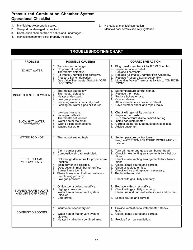
26
TROUBLESHOOTING CHART
PROBLEM POSSIBLE CAUSE(S) CORRECTIVE ACTION
NO HOT WATER1. Transformer unplugged.2. No power at outlet.3. Thermostat defective.4. Air Intake Chamber Fan defective.5. Pressure Switch defective.6. Gas Valve/Thermostat Switch in “OFF
POSITION”.
1. Plug transformer back into 120 VAC. outlet.2. Repair service to outlet.3. Replace Thermostat.4. Replace Air Intake Chamber Fan Assembly.5. Replace Pressure Switch Assembly.6. Move Gas Valve/Thermostat Switch to “ON POSI-
TION”.
INSUFFICIENT HOT WATER1. Thermostat set too low.2. Thermostat defective.3. Heater undersized.4. Low gas pressure.5. Incoming water is unusually cold.6. Leaking hot water pipes or fixtures.
1. Set temperature control higher.2. Replace thermostat.3. Reduce hot water use.4. Contact dealer.5. Allow more time for heater to reheat.6. Have plumber check and repair leaks.
SLOW HOT WATER RECOVERY
1. Low gas pressure.2. Improper calibration.3. Thermostat set too low.4. Water heater too small.5. Wrong piping connections.6. Wasted hot water.
1. Check with gas utility company.2. Replace thermostat.3. Turn temperature dial to desired setting.4. Install adequate heater.5. Correct piping-dip tube must be in cold inlet.6. Advise customer.
WATER TOO HOT 1. Thermostat set too high. 1. Set temperature control lower. see, “WATER TEMPERATURE REGULATION”,
section.
BURNER FLAME YELLOW - LAZY
1. Dirt in burner ports.2. Combustion air path restricted.
3. Not enough dilution air for proper com-bustion.
4. Main burner line clogged.5. Obstruction in main burner orifice.6. Burner flame too high.7. Flame burns at orifice/thermostat not
functioning properly.8. Low gas pressure.
1. Turn off heater and gas, clean burner head.2. Check intake venting arrangements for obstruc-
tions.3. Check intake venting arrangements for obsruc-
tions.4. Clean, locate source and correct.5. Clean or replace orifice.6. Check orifice and replace if necessary.7. Replace thermostat
8. Check with gas utility company.
BURNER FLAME FLOATS AND LIFTS OFF PORTS
1. Orifice too large/wrong orifice.2. High gas pressure.3. Water heater flue or vent system
blocked.4. Cold drafts.
1. Replace with correct-orifice.2. Check with gas utility company.3. Clean flue and burner-locate source and correct.
4. Locate source and correct.
COMBUSTION ODORS1. Insufficient secondary air.
2. Water heater flue or vent system blocked.3. Heater installed in a confined area.
1. Provide ventilation to water heater. Check flue.2. Clean, locate source and correct.
3. Provide fresh air ventilation.
Pressurized Combustion Chamber System Operational Checklist1. Manifold gasket properly sealed.2. Viewport not damaged or cracked.3. Combustion chamber free of debris and undamaged.4. Manifold component block properly installed.
5. No leaks at manifold connection.6. Manifold door screws securely tightened.
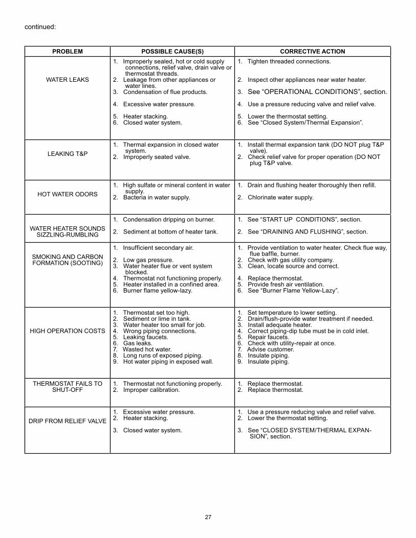
27
PROBLEM POSSIBLE CAUSE(S) CORRECTIVE ACTION
WATER LEAKS
1. Improperly sealed, hot or cold supply connections, relief valve, drain valve or thermostat threads.
2. Leakage from other appliances or water lines.
3. Condensation of flue products.
4. Excessive water pressure.
5. Heater stacking.6. Closed water system.
1. Tighten threaded connections.
2. Inspect other appliances near water heater.
3. See “OPERATIONAL CONDITIONS”, section.
4. Use a pressure reducing valve and relief valve.
5. Lower the thermostat setting.6. See “Closed System/Thermal Expansion”.
LEAKING T&P
1. Thermal expansion in closed water system.
2. Improperly seated valve.
1. Install thermal expansion tank (DO NOT plug T&P valve).
2. Check relief valve for proper operation (DO NOT plug T&P valve.
HOT WATER ODORS1. High sulfate or mineral content in water
supply.2. Bacteria in water supply.
1. Drain and flushing heater thoroughly then refill.
2. Chlorinate water supply.
WATER HEATER SOUNDS SIZZLING-RUMBLING
1. Condensation dripping on burner.
2. Sediment at bottom of heater tank.
1. See “START UP CONDITIONS”, section.
2. See “DRAINING AND FLUSHING”, section.
SMOKING AND CARBON FORMATION (SOOTING)
1. Insufficient secondary air.
2. Low gas pressure.3. Water heater flue or vent system
blocked.4. Thermostat not functioning properly.5. Heater installed in a confined area.6. Burner flame yellow-lazy.
1. Provide ventilation to water heater. Check flue way, flue baffle, burner.
2. Check with gas utility company.3. Clean, locate source and correct.
4. Replace thermostat.5. Provide fresh air ventilation.6. See “Burner Flame Yellow-Lazy”.
HIGH OPERATION COSTS
1. Thermostat set too high.2. Sediment or lime in tank.3. Water heater too small for job.4. Wrong piping connections.5. Leaking faucets.6. Gas leaks. 7. Wasted hot water.8. Long runs of exposed piping.9. Hot water piping in exposed wall.
1. Set temperature to lower setting.2. Drain/flush-provide water treatment if needed.3. Install adequate heater.4. Correct piping-dip tube must be in cold inlet.5. Repair faucets.6. Check with utility-repair at once.7. Advise customer.8. Insulate piping.9. Insulate piping.
THERMOSTAT FAILS TO SHUT-OFF
1. Thermostat not functioning properly.2. Improper calibration.
1. Replace thermostat.2. Replace thermostat.
DRIP FROM RELIEF VALVE1. Excessive water pressure.2. Heater stacking.
3. Closed water system.
1. Use a pressure reducing valve and relief valve.2. Lower the thermostat setting.
3. See “CLOSED SYSTEM/THERMAL EXPAN-SION”, section.
continued:
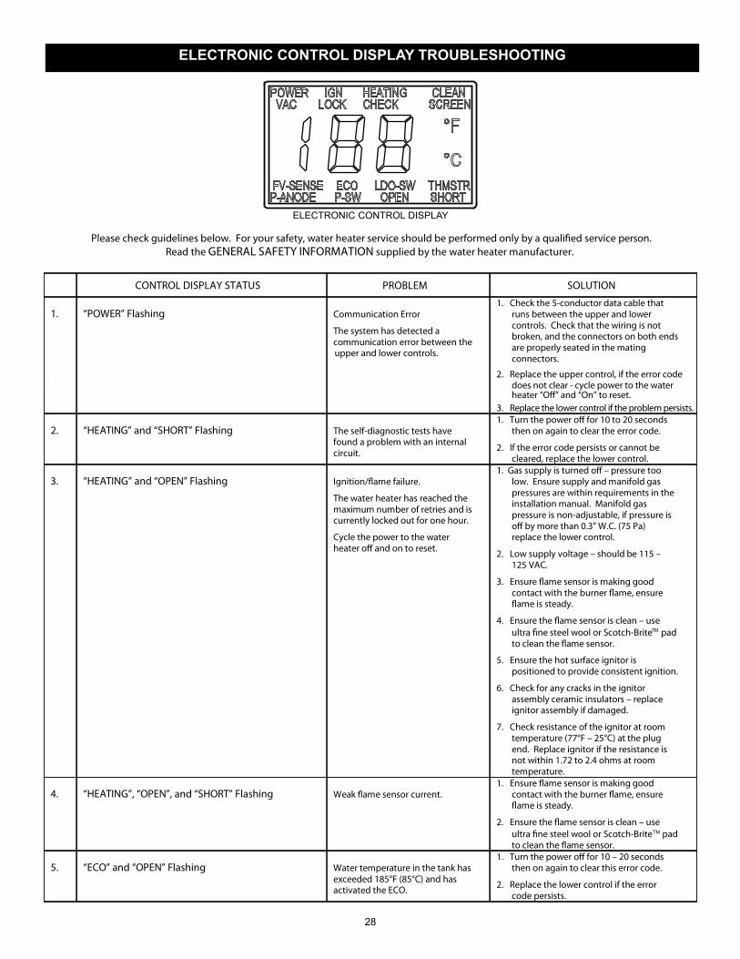
28
Please check guidelines below. For your safety, water heater service should be performed only by a qualified service person.Read the GENERAL SAFETY INFORMATION supplied by the water heater manufacturer.
1.
“POWER” Flashing
Communication Error
The system has detected a communication error between the upper and lower controls.
1. Check the 5-conductor data cable that runs between the upper and lower controls. Check that the wiring is not broken, and the connectors on both ends are properly seated in the mating connectors.
2. Replace the upper control, if the error codedoes not clear - cycle power to the water heater “Off” and “On” to reset.
3. Replace the lower control if the problem persists. 2.
“HEATING” and “SHORT” Flashing
The self-diagnostic tests have found a problem with an internal circuit.
1. Turn the power off for 10 to 20 seconds then on again to clear the error code.
2. If the error code persists or cannot be cleared, replace the lower control.
3.
“HEATING” and “OPEN” Flashing
Ignition/flame failure.
The water heater has reached the maximum number of retries and is currently locked out for one hour.
Cycle the power to the water heater off and on to reset.
1. Gas supply is turned off – pressure too low. Ensure supply and manifold gas pressures are within requirements in the installation manual. Manifold gas pressure is non-adjustable, if pressure is off by more than 0.3” W.C. (75 Pa) replace the lower control.
2. Low supply voltage – should be 115 – 125 VAC.
3. Ensure flame sensor is making good contact with the burner flame, ensure flame is steady.
4. Ensure the flame sensor is clean – use pad
to clean the flame sensor.
5. Ensure the hot surface ignitor is positioned to provide consistent ignition.
6. Check for any cracks in the ignitor assembly ceramic insulators – replace ignitor assembly if damaged.
7. Check resistance of the ignitor at room temperature (77°F – 25°C) at the plug end. Replace ignitor if the resistance is not within 1.72 to 2.4 ohms at room temperature.
4.
“HEATING”, “OPEN”, and “SHORT” Flashing
Weak flame sensor current.
1. Ensure flame sensor is making good contact with the burner flame, ensure flame is steady.
2. Ensure the flame sensor is clean – use ultra fine steel wool or Scotch-Brite pad to clean the flame sensor.
5.
“ECO” and “OPEN” Flashing
Water temperature in the tank has exceeded 185°F (85°C) and has activated the ECO.
1. Turn the power off for 10 – 20 seconds then on again to clear this error code.
2. Replace the lower control if the error code persists.
ultra fine steel wool or Scotch-BriteTM
TM
CONTROL DISPLAY STATUS PROBLEM SOLUTION
ELECTRONIC CONTROL DISPLAY
ELECTRONIC CONTROL DISPLAY TROUBLESHOOTING
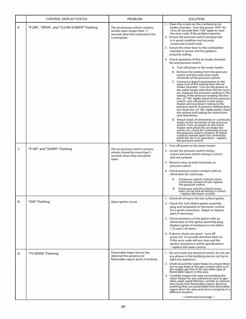
29
6.
“P-SW”, “OPEN”, and “CLEAN SCREEN” Flashing
The air pressure switch contacts remain open longer than 11 seconds after the combustion fan is energized.
1. Clean the screen on the combustion air intake chamber. Turn the power “OFF” for 10 to 20 seconds then “ON” again to clear
2. Ensure the pressure switch sensing tube is in good condition and securely connected at both ends.
3. Ensure the inner door to the combustion chamber is secure and the gasket is properly sealing.
4. Check operation of the air intake chamber
A. Turn off power to the water heater.
B. Remove the tubing from the pressure switch and the wires from both
7.
“P-SW” and “SHORT” Flashing
The air pressure switch contacts remain closed for more than 5 seconds when they should be open.
1. Turn off power to the water heater.
2. Locate the pressure switch wiring – ensure pressure switch wiring is correct and not jumped.
3. Remove wires to both terminals on pressure switch.
4. Check pressure switch contacts with an ohmmeter for continuity.
A. If pressure switch contacts show continuity (closed circuit) replace the pressure switch.
B. If pressure switch contacts show open circuit and all wiring is correct – replace the lower control.
8.
“IGN” Flashing
Open ignitor circuit
1. Check all wiring to the hot surface ignitor.
2. Check the 3 pin Molex ignitor assembly plug and receptacle on the lower control for a good connection. Repair or replace parts if necessary.
3. Check resistance of the ignitor with an ohmmeter on the ignitor assembly plug. Replace ignitor if resistance is not within 1.72 and 2.40 ohms.
4. If above checks are good – turn off power for 10 seconds and then back on. If this error code will not clear and the ignitor resistance is within specifications – replace the lower control.
9. “FV-SENSE” Flashing
Flammable Vapor Sensor has detected the presence of flammable vapors and is in lockout
1. Do not touch any electrical switch, do not useany phone in the building and do not try to
CONTROL DISPLAY STATUS PROBLEM SOLUTION
the error code. If the problem persists:
fan and pressure switch.
terminals of the pressure switch. C. Connect a digital manometer to the
open end of the tubing from the air intake chamber. Turn on the power to the water heater and when the fan turnson, measure the pressure reading in thetubing. If the pressure reading reachesthe .22” WC make point of the pressureswitch, turn off power to the waterheater and reconnect tubing to the pressure switch. If pressure reading doesnot reach the .22” WC make point, checkthe system and tubing for restrictionsand cleanliness.
D. Attach leads of ohmmeter or continuitytester to the terminals of the pressureswitch. Turn on power to the water heater and when the air intake fancomes on, check for continuity acrossthe pressure switch contacts. If switchcontacts remain open (no continuity)while the fan is in operation - replacethe pressure switch.
light any appliance.
2. Smell around the water heater to ensure thereare no gas leaks at the gas control valve or in the supply gas line or for any other type offlammable vapors in the area.
3. Carefully inspect the area surrounding the water heater for any substances such as gas-oline, paint, paint thinners, varnish, or cleanersthat could emit flammable vapors. Remove anything that can potentially emit flammable vapors from the area and store it properly in adifferent location.
~ continued next page ~
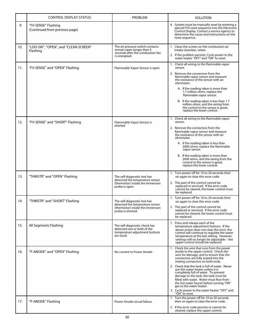
30
11.
“FV-SENSE” and “OPEN” Flashing
Flammable Vapor Sensor is open
1. Check all wiring to the flammable vapor sensor.
2. Remove the connectors from the flammable vapor sensor and measure the resistance of the sensor with an ohmmeter.
A. If the reading taken is more than 1.7 million ohms, replace the flammable vapor sensor.
B. If the reading taken is less than 1.7 million ohms, and the wiring from the control to the sensor is good, replace the lower control.
12.
“FV-SENSE” and “SHORT” Flashing
Flammable Vapor Sensor is shorted
1. Check all wiring to the flammable vapor sensor.
2. Remove the connectors from the flammable vapor sensor and measure the resistance of the sensor with an ohmmeter.
A. If the reading taken is less than 2000 ohms, replace the flammable vapor sensor.
B. If the reading taken is more than 2000 ohms, and the wiring from the control to the sensor is good, replace the lower control.
13.
“THMSTR” and “OPEN” Flashing
The self-diagnostic test has detected the temperature sensor (thermistor) inside the immersion probe is open.
1. Turn power off for 10 to 20 seconds then on again to clear this error code.
2. This part of the control cannot be replaced or serviced. If the error code cannot be cleared, the lower control must be replaced.
14.
“THMSTR” and “SHORT” Flashing
The self-diagnostic test has detected the temperature sensor (thermistor) inside the immersion probe is shorted.
1. Turn power off for 10 to 20 seconds then on again to clear this error code.
2. This part of the control cannot be replaced or serviced. If the error code cannot be cleared, the lower control must be replaced.
15.
All Segments Flashing
The self-diagnostic check has detected one or both of the temperature adjustment buttons are stuck.
1. Press and release each of the temperature adjustment buttons. If the above action does not clear the error, the control will continue to regulate the water temperature at the last setting. However, settings will no longer be adjustable – the upper control should be replaced.
16.
“P-ANODE” and “OPEN” Flashing
No current to Power Anode.
1. Check the wire that runs from the power anode to the upper control. Check the wire for damage, and to ensure that the connectors are fully seated into the mating connectors on both ends.
2. Check that the tank is full of water. Never use this water heater unless it is completely full of water. To prevent damage to the tank, the tank must be filled with water. Water must flow from the hot water faucet before turning “ON” gas to the water heater.
17.
“P-ANODE” Flashing
Power Anode circuit failure. 1. Turn the power off for 10 to 20 seconds
then on again to clear the error code.
2. If the error code persists or cannot be cleared, replace the upper control.
10.
“LDO-SW”, “OPEN”, and “CLEAN SCREEN” Flashing
1. Clean the screen on the combustion air
intake chamber, retest.
The air pressure switch contacts remain open longer than 5 seconds after the combustion fan is energized.
4. System must be manually reset by entering aspecial FVS reset sequence into the ElectronicControl Display. Contact a service agency todetermine the cause and instructions on the reset sequence.
9. “FV-SENSE” Flashing(Continued from previous page)
CONTROL DISPLAY STATUS PROBLEM SOLUTION
2. If the problem persists: Cycle power to thewater heater “OFF” and “ON” to reset.
3. Cycle power to the water heater “OFF” and“ON” to reset.
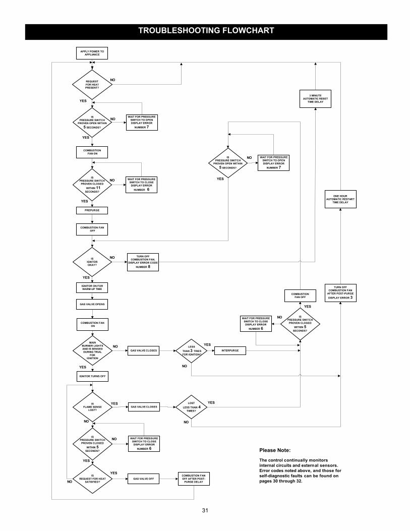
31
Please Note:
The control continually monitorsinternal circuits and external sensors.Error codes noted above, and those forself-diagnostic faults can be found onpages 30 through 32.
APPLY POWER TOAPPLIANCE
YES
REQUESTFOR HEATPRESENT?
NO
ISPRESSURE SWITCH
PROVEN OPEN WITHIN5 SECONDS?
NO
COMBUSTION FAN ON
YES
ISPRESSURE SWITCH
PROVEN CLOSEDWITHIN 11
SECONDS?
NO
WAIT FOR PRESSURESWITCH TO OPENDISPLAY ERROR
NUMBER 7
WAIT FOR PRESSURESWITCH TO CLOSE
DISPLAY ERRORNUMBER 6
PREPURGE
ISIGNITOROKAY?
TURN OFFCOMBUSTION FAN,
DISPLAY ERROR CODENUMBER 8
NO
IGNITOR ON FORWARM-UP TIME
YES
GAS VALVE OPENS
MAINBURNER LIGHTSAND IS SENSEDDURING TRIAL
FORIGNITION
IGNITOR TURNS OFF
YES
NO
ISFLAME SENSE
LOST?
ISREQUEST FOR HEAT
SATISFIED?GAS VALVE OFF
COMBUSTION FANOFF AFTER POST-
PURGE DELAY
GAS VALVE CLOSESLESS
THAN 3 TRIES FOR IGNITION?
GAS VALVE CLOSESLOST
LESS THAN 4TIMES?
YES
YES
TURN OFFCOMBUSTION FAN
AFTER POST-PURGEDISPLAY ERROR 3
ONE HOURAUTOMATIC RESTART
TIME DELAY
NO
NONO
YES
YES
NO
ISPRESSURE SWITCH
PROVEN OPEN WITHIN5 SECONDS?
WAIT FOR PRESSURESWITCH TO OPENDISPLAY ERROR
NUMBER 7
INTERPURGE
COMBUSTIONFAN OFF
YES
NO
YES
COMBUSTION FAN OFF
COMBUSTION FAN ON
3 MINUTEAUTOMATIC RESET
TIME DELAY
ISPRESSURE SWITCHPROVEN CLOSED
WITHIN 5SECONDS?
WAIT FOR PRESSURESWITCH TO CLOSEDISPLAY ERROR
NUMBER 6
NO
YES
ISPRESSURE SWITCH
PROVEN CLOSEDWITHIN 5
SECONDS?
WAIT FOR PRESSURESWITCH TO CLOSEDISPLAY ERROR
NUMBER 6
YES
NO
TROUBLESHOOTING FLOWCHART
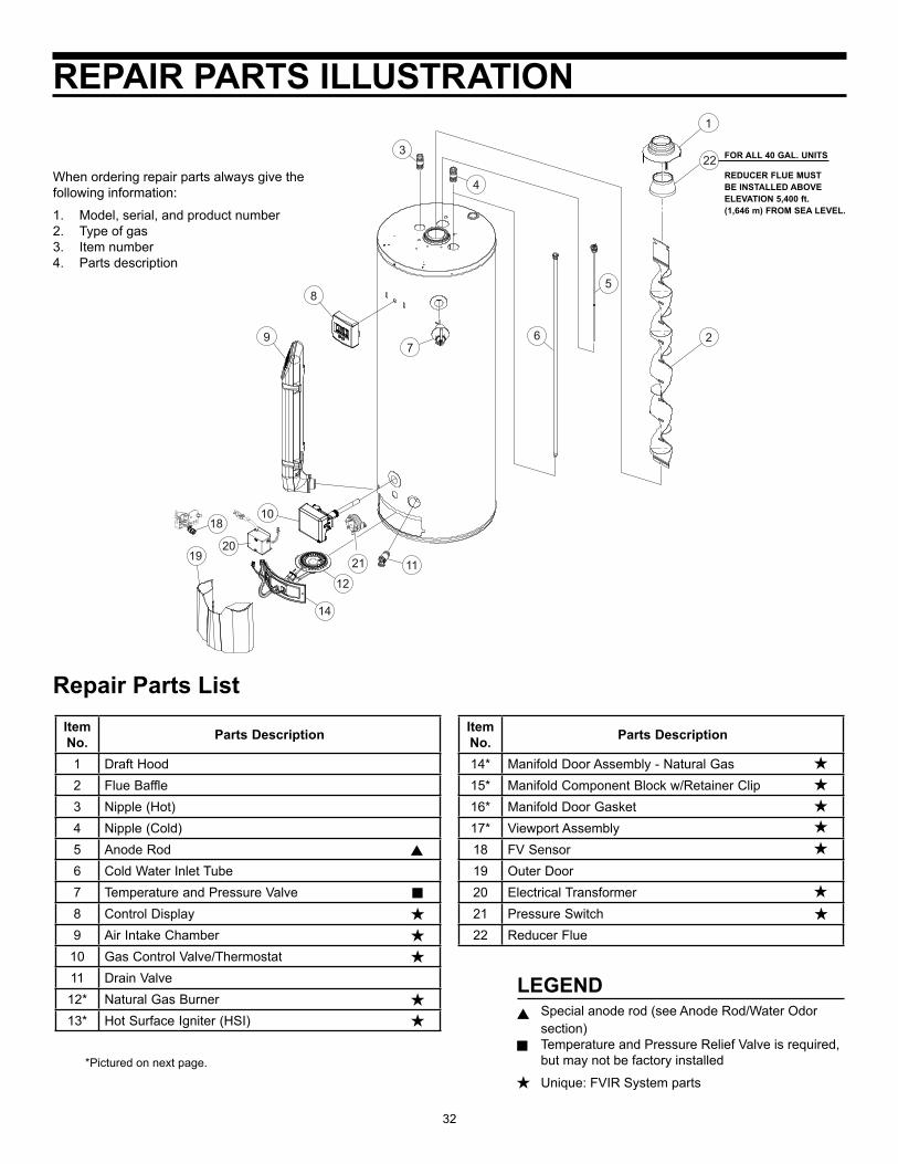
32
LEGENDSpecial anode rod (see Anode Rod/Water Odor section)Temperature and Pressure Relief Valve is required, but may not be factory installed
Unique: FVIR System parts
Repair Parts List
When ordering repair parts always give the following information:
1. Model, serial, and product number2. Type of gas3. Item number4. Parts description
*Pictured on next page.
Item No. Parts Description
1 Draft Hood2 Flue Baffle3 Nipple (Hot)4 Nipple (Cold)5 Anode Rod6 Cold Water Inlet Tube7 Temperature and Pressure Valve8 Control Display9 Air Intake Chamber
10 Gas Control Valve/Thermostat11 Drain Valve12* Natural Gas Burner13* Hot Surface Igniter (HSI)
4
1
2
3
6
5
7
8
9
10
1112
14
19
18
2120
22 FOR ALL 40 GAL. UNITS
REDUCER FLUE MUST BE INSTALLED ABOVE ELEVATION 5,400 ft. (1,646 m) FROM SEA LEVEL.
Item No. Parts Description
14* Manifold Door Assembly - Natural Gas15* Manifold Component Block w/Retainer Clip16* Manifold Door Gasket17* Viewport Assembly18 FV Sensor19 Outer Door20 Electrical Transformer21 Pressure Switch22 Reducer Flue
REPAIR PARTS ILLUSTRATION
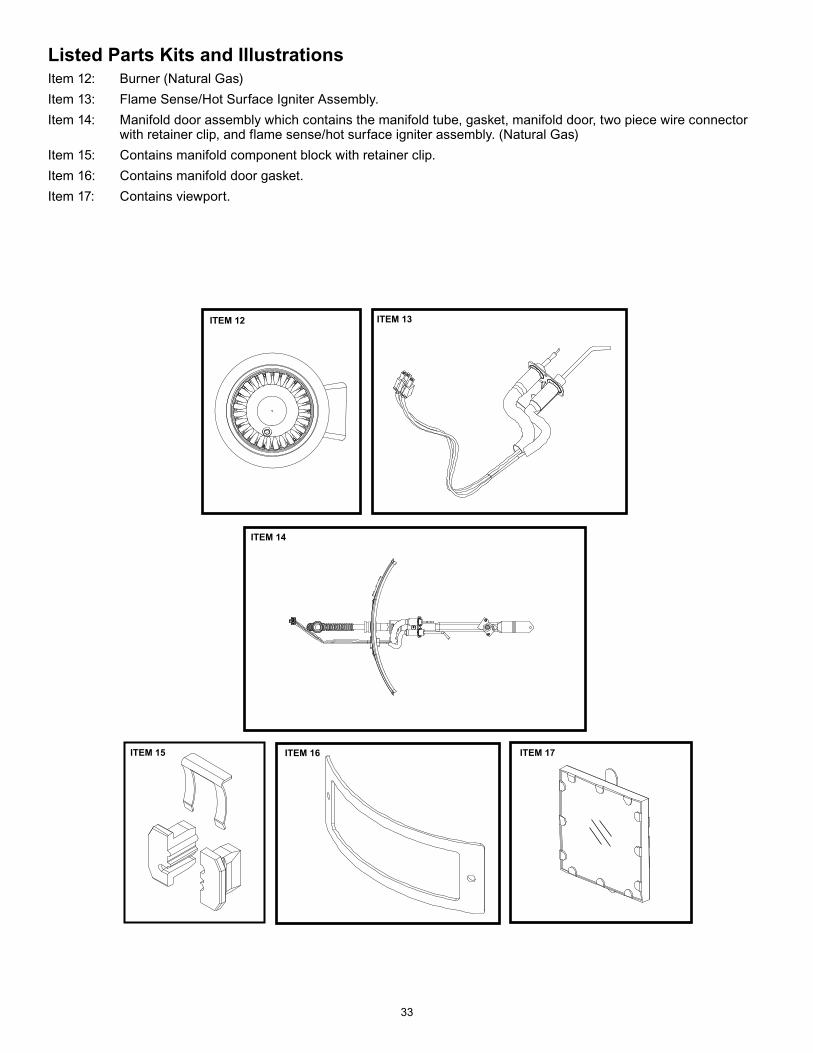
33
Listed Parts Kits and IllustrationsItem 12: Burner (Natural Gas)Item 13: Flame Sense/Hot Surface Igniter Assembly. Item 14: Manifold door assembly which contains the manifold tube, gasket, manifold door, two piece wire connector
with retainer clip, and flame sense/hot surface igniter assembly. (Natural Gas)Item 15: Contains manifold component block with retainer clip.Item 16: Contains manifold door gasket.Item 17: Contains viewport.
ITEM 13ITEM 12
ITEM 14
ITEM 15 ITEM 16 ITEM 17

34
NOTES

35
NOTES

36
® Registered trademark/TM trademark of Whirlpool, U.S.A.© 2011 Whirlpool Corporation. All rights reserved.
Manufactured under license by American Water Heater Company, Tennessee.Warranty provided by manufacturer.