Embed Size (px)
Citation preview
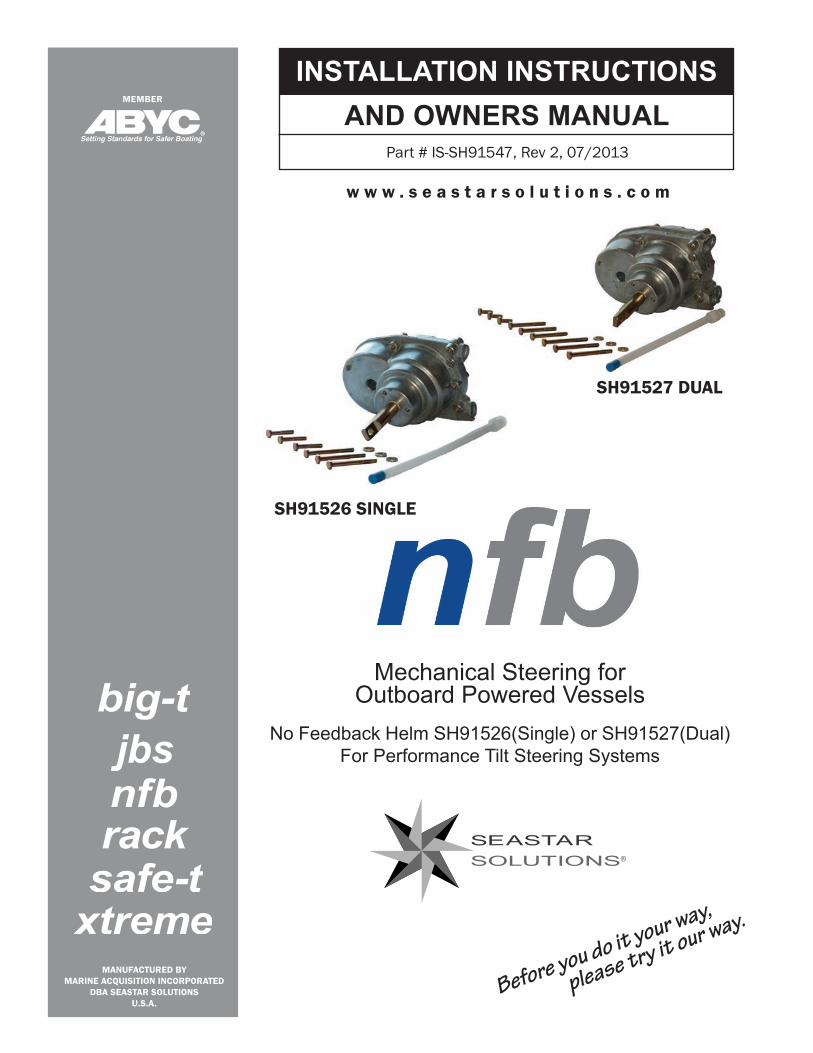
Mechanical Steering for Outboard Powered Vessels
No Feedback Helm SH91526(Single) or SH91527(Dual)For Performance Tilt Steering Systems
w w w . s e a s t a r s o l u t i o n s . c o m
®
Before you do it your way,
please try it our way.
nfb
MANUFACTURED BYMARINE ACQUISITION INCORPORATED
DBA SEASTAR SOLUTIONSU.S.A.
MEMBER
INSTALLATION INSTRUCTIONSAND OWNERS MANUAL
Part # IS-SH91547, Rev 2, 07/2013
jbs
SH91526 SINGLE
SH91527 DUAL
PERFORMANCE TILT SYSTEM4.2 TURN ROTARYNO FEEDBACK HELM SH91526 Single, SH91527 Dual
Before starting installation read these instructions and engine makers instructions thoroughly. Failure to follow either of these instructions or incorrect assembly can result in loss of control and cause property damage, injury, or death.
DO NOT substitute parts from other manufacturers, they may cause a safety hazard for which SeaStar Solutions cannot accept responsibility. Use only SeaStar Solutions steering cables with this helm.
To avoid excessive steering loads, and to get the best steering performance, the outboard motor or outdrive trim tabs and tilt position must be adjusted as instructed in the motor manufacturers operation manual. Failure to do so can effect the performance of the boat and its safe operation which may cause property damage, injury, or death.
WARNING
Installer: these instructions contain important safety information and must be forwarded to the boat owner.
NOTICE
These instructions describe how to install NO FEEDBACK HELMS for PERFORMANCE TILT steering systems. These helms contain a clutch mechanism to prevent the engine torque from being felt at the steering wheel. This reduces driver fatigue by eliminating constant fighting the wheel. It does not eliminate the engine torque. This can only be reduced by proper trim and tilt setting by trial and error when running the boat. Instructions for installing steering cables are also included.In addition to this kit the following components are required for a complete PERFORMANCE TILT system:• SH91800 Sport or SH91900 Sport Plus Tilt Mecansism• SSC62xx Steering cable (where xx is the length in feet) Two required
for dual helm.• Engine Connection Kit (refer to SeaStar Solutions catalog)• Steering Wheel (refer to SeaStar Solutions catalog) Maximum
wheel diameter 16", maximum wheel dish 5".
WARNING
WARNING
DO NOT attach any electrical ground wires to the helm. This would result in an electrolytic reaction to the steering system that may result in system failure or greatly reduced service life.
WARNING
Helms and cable assemblies are supplied lubricated ready for installation, do not add any lubricant to either assembly. Use of other lubricants can cause damage to the steering cable, resulting in the cable seizing or premature wear. Keep the cable and drive assembly clean during installation. Dirt will damage the system and cause premature wear.This notice does not include the engine output ram end of the cable.
NOTICE
When replacing an existing steering system it is recommended that you stay with the style (rotary or rack) the boat manufacturer installed. Never change your steering from a dual cable to a single cable system, as this could cause an unsafe boating condition.
NOTICE
Page 2 of 8 SeaStar Solutions Installation Instructions and Owner’s Manual Telephone: 610-495-7011
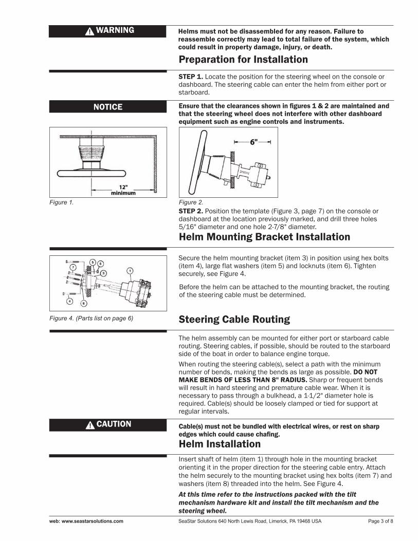
Ensure that the clearances shown in figures 1 & 2 are maintained and that the steering wheel does not interfere with other dashboard equipment such as engine controls and instruments.
Figure 1. Figure 2.
Preparation for InstallationSTEP 1. Locate the position for the steering wheel on the console or dashboard. The steering cable can enter the helm from either port or starboard.
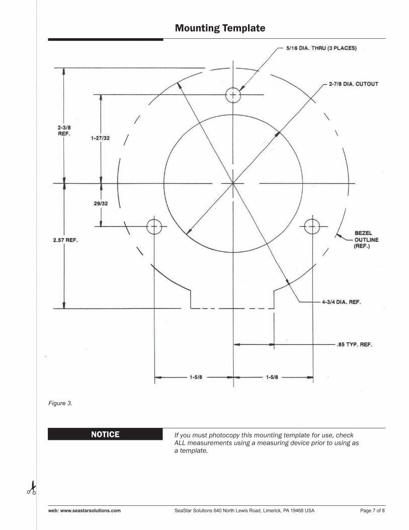
STEP 2. Position the template (Figure 3, page 7) on the console or dashboard at the location previously marked, and drill three holes 5/16" diameter and one hole 2-7/8" diameter.
Helms must not be disassembled for any reason. Failure to reassemble correctly may lead to total failure of the system, which could result in property damage, injury, or death.
WARNING
NOTICE
Secure the helm mounting bracket (item 3) in position using hex bolts (item 4), large flat washers (item 5) and locknuts (item 6). Tighten securely, see Figure 4.
Helm Mounting Bracket Installation
Figure 4. (Parts list on page 6)
Before the helm can be attached to the mounting bracket, the routing of the steering cable must be determined.
Steering Cable Routing
Insert shaft of helm (item 1) through hole in the mounting bracket orienting it in the proper direction for the steering cable entry. Attach the helm securely to the mounting bracket using hex bolts (item 7) and washers (item 8) threaded into the helm. See Figure 4.At this time refer to the instructions packed with the tilt mechanism hardware kit and install the tilt mechanism and the steering wheel.
Helm Installation
Cable(s) must not be bundled with electrical wires, or rest on sharp edges which could cause chafing.
CAUTION
The helm assembly can be mounted for either port or starboard cable routing. Steering cables, if possible, should be routed to the starboard side of the boat in order to balance engine torque. When routing the steering cable(s), select a path with the minimum number of bends, making the bends as large as possible. DO NOT MAKE BENDS OF LESS THAN 8" RADIUS. Sharp or frequent bends will result in hard steering and premature cable wear. When it is necessary to pass through a bulkhead, a 1-1/2" diameter hole is required. Cable(s) should be loosely clamped or tied for support at regular intervals.
web: www.seastarsolutions.com SeaStar Solutions 640 North Lewis Road, Limerick, PA 19468 USA Page 3 of 8
STEP 1. Remove the protective sleeve from the cable end, making sure that no dirt gets on the lubricated cable end.
STEP 2. Feed the cable into the UPPER helm spigot until it contacts the internal gear. Then turn steering wheel to draw the cable fully into the helm (see Figure 6). Continue turning the steering wheel until the end fitting of the cable is fully inserted into the entry spigot.
STEP 3. Insert two bolts (item 9) into the helm and tighten fully, making sure that the bolts are in the retaining groove of the cable fitting. See Figure 6.
STEP 4. Feed spent travel tube (item 2) over the exposed cable end and insert bolt (item 9) into the helm, tighten fully. See Figure 6.
STEP 5. Rotate the steering wheel several times from stop to stop, and watch the movement of the Steering Cable output ram. On starboard routed cables, turning the steering wheel clockwise should cause the ram to extend. On port routed cables, turning the steering wheel clockwise should cause the ram to retract. Figure 6.
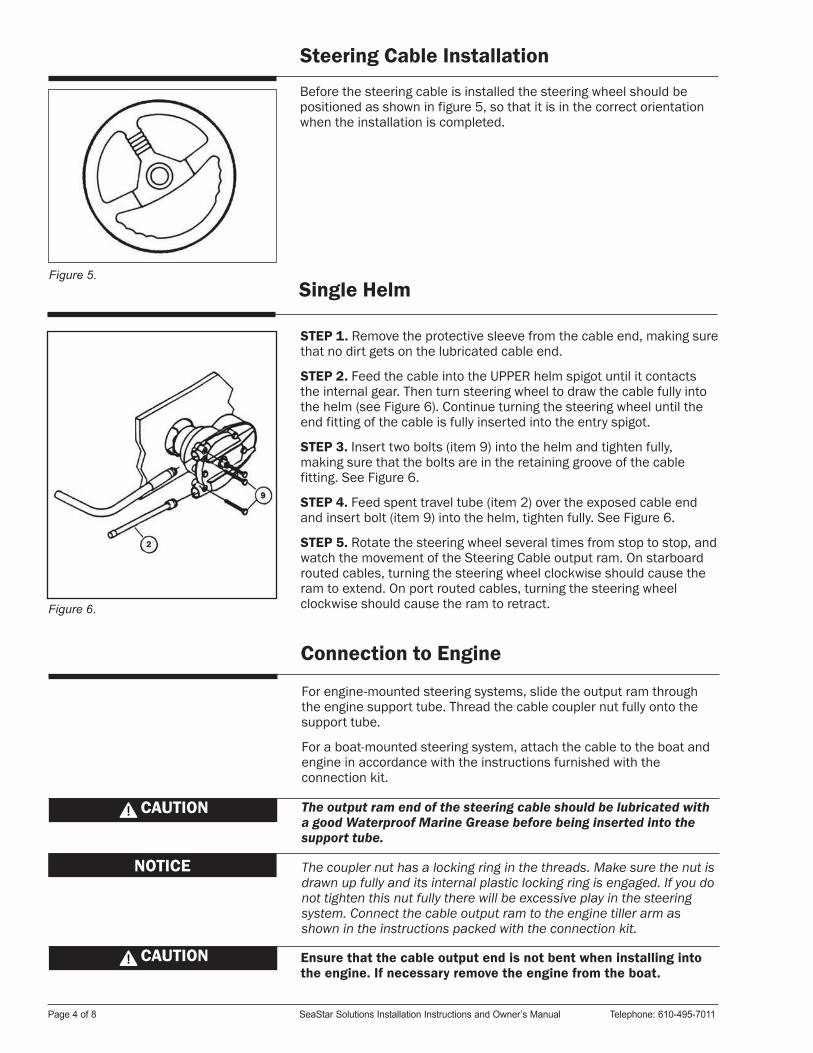
Figure 5.
Before the steering cable is installed the steering wheel should be positioned as shown in figure 5, so that it is in the correct orientation when the installation is completed.
Steering Cable Installation
Single Helm
For engine-mounted steering systems, slide the output ram through the engine support tube. Thread the cable coupler nut fully onto the support tube.
For a boat-mounted steering system, attach the cable to the boat and engine in accordance with the instructions furnished with the connection kit.
The output ram end of the steering cable should be lubricated with a good Waterproof Marine Grease before being inserted into the support tube.
The coupler nut has a locking ring in the threads. Make sure the nut is drawn up fully and its internal plastic locking ring is engaged. If you do not tighten this nut fully there will be excessive play in the steering system. Connect the cable output ram to the engine tiller arm as shown in the instructions packed with the connection kit.
NOTICE
Ensure that the cable output end is not bent when installing into the engine. If necessary remove the engine from the boat.
CAUTION
Connection to Engine
CAUTION
Page 4 of 8 SeaStar Solutions Installation Instructions and Owner’s Manual Telephone: 610-495-7011
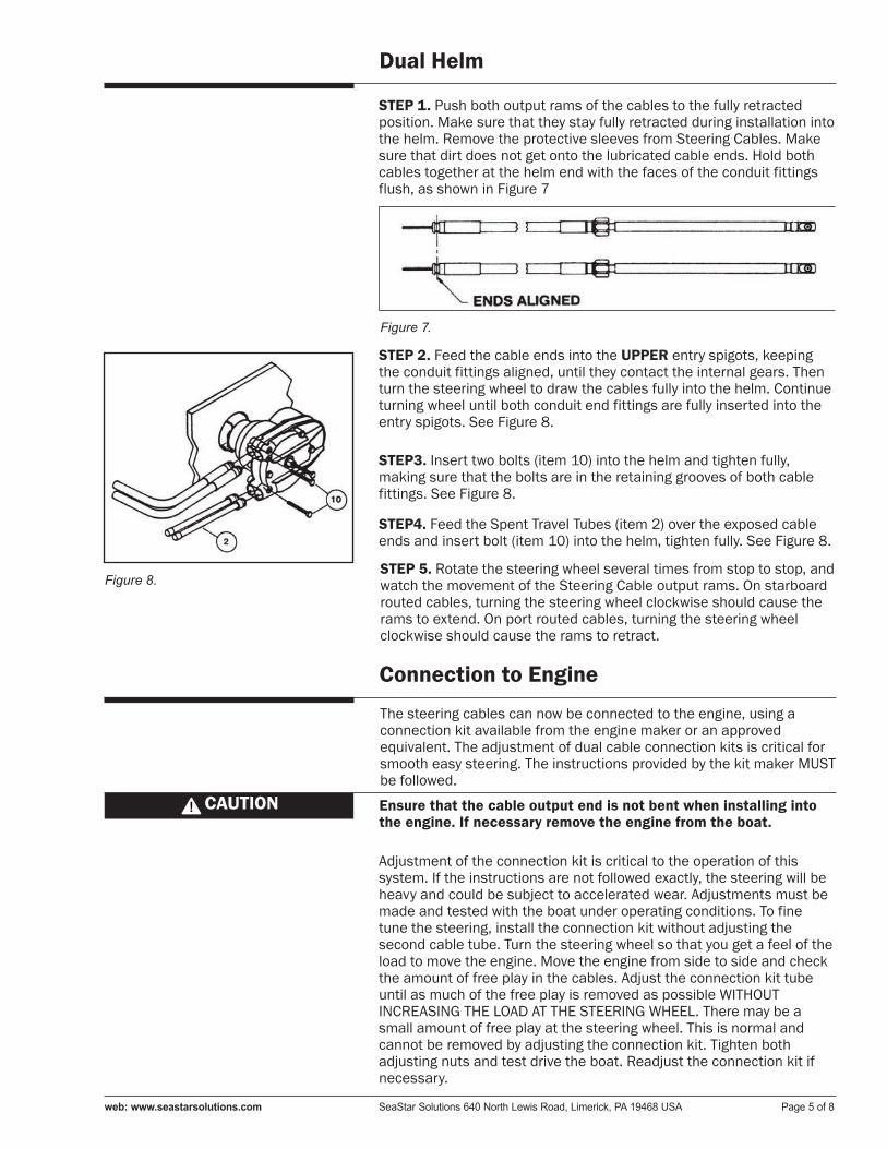
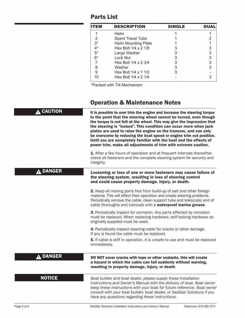
Figure 7.
Dual Helm
STEP3. Insert two bolts (item 10) into the helm and tighten fully, making sure that the bolts are in the retaining grooves of both cable fittings. See Figure 8.
STEP 1. Push both output rams of the cables to the fully retracted position. Make sure that they stay fully retracted during installation into the helm. Remove the protective sleeves from Steering Cables. Make sure that dirt does not get onto the lubricated cable ends. Hold both cables together at the helm end with the faces of the conduit fittings flush, as shown in Figure 7
STEP 2. Feed the cable ends into the UPPER entry spigots, keeping the conduit fittings aligned, until they contact the internal gears. Then turn the steering wheel to draw the cables fully into the helm. Continue turning wheel until both conduit end fittings are fully inserted into the entry spigots. See Figure 8.
STEP4. Feed the Spent Travel Tubes (item 2) over the exposed cable ends and insert bolt (item 10) into the helm, tighten fully. See Figure 8.
Connection to Engine
The steering cables can now be connected to the engine, using a connection kit available from the engine maker or an approved equivalent. The adjustment of dual cable connection kits is critical for smooth easy steering. The instructions provided by the kit maker MUST be followed.
Ensure that the cable output end is not bent when installing into the engine. If necessary remove the engine from the boat.
CAUTION
Adjustment of the connection kit is critical to the operation of this system. If the instructions are not followed exactly, the steering will be heavy and could be subject to accelerated wear. Adjustments must be made and tested with the boat under operating conditions. To fine tune the steering, install the connection kit without adjusting the second cable tube. Turn the steering wheel so that you get a feel of the load to move the engine. Move the engine from side to side and check the amount of free play in the cables. Adjust the connection kit tube until as much of the free play is removed as possible WITHOUT INCREASING THE LOAD AT THE STEERING WHEEL. There may be a small amount of free play at the steering wheel. This is normal and cannot be removed by adjusting the connection kit. Tighten both adjusting nuts and test drive the boat. Readjust the connection kit if necessary.
Figure 8. STEP 5. Rotate the steering wheel several times from stop to stop, and watch the movement of the Steering Cable output rams. On starboard routed cables, turning the steering wheel clockwise should cause the rams to extend. On port routed cables, turning the steering wheel clockwise should cause the rams to retract.
web: www.seastarsolutions.com SeaStar Solutions 640 North Lewis Road, Limerick, PA 19468 USA Page 5 of 8
Loosening or loss of one or more fasteners may cause failure of the steering system, resulting in loss of steering control and could cause property damage, injury, or death.
DO NOT cover cracks with tape or other sealants, this will create a hazard in which the cable can fail suddenly without warning, resulting in property damage, injury, or death.
DANGER
DANGER
1. After a few hours of operation and at frequent intervals thereafter, check all fasteners and the complete steering system for security and integrity.
2. Keep all moving parts free from build-up of salt and other foreign material. This will affect their operation and create steering problems. Periodically remove the cable, clean support tube and telescopic end of cable thoroughly and lubricate with a waterproof marine grease.
3. Periodically inspect for corrosion. Any parts affected by corrosion must be replaced. When replacing hardware, self-locking hardware as originally supplied must be used.
4. Periodically inspect steering cable for cracks or other damage. If any is found the cable must be replaced.5. If cable is stiff in operation, it is unsafe to use and must be replaced immediately.
Boat builder and boat dealer, please supply these Installation Instructions and Owner’s Manual with the delivery of boat. Boat owner keep these instructions with your boat for future reference. Boat owner consult with your boat builder, boat dealer, or SeaStar Solutions if you have any questions regarding these instructions.
NOTICE
Operation & Maintenance Notes
Parts ListITEM DESCRIPTION SINGLE DUAL
123*4*5*6*78910
HelmSpent Travel TubeHelm Mounting PlateHex Bolt 1/4 x 2 1/8Large WasherLock NutHex Bolt 1/4 x 2 3/4Washer Hex Bolt 1/4 x 1 1/2Hex Bolt 1/4 x 2 1/4
111333333-
12133333-3
It is possible to over trim the engine and increase the steering torque to the point that the steering wheel cannot be turned, even though the torque is not felt at the wheel. This may give the impression that the steering is “locked”. This condition can occur more when jack plates are used to raise the engine on the transom, and can only be overcome by reducing the boat speed or engine trim out position. Until you are completely familiar with the boat and the effects of power trim, make all adjustments of trim with extreme caution.
CAUTION
*Packed with Tilt Mechanism
Page 6 of 8 SeaStar Solutions Installation Instructions and Owner’s Manual Telephone: 610-495-7011
Mounting Template
If you must photocopy this mounting template for use, check ALL measurements using a measuring device prior to using as a template.
NOTICE
Figure 3.
✁
web: www.seastarsolutions.com SeaStar Solutions 640 North Lewis Road, Limerick, PA 19468 USA Page 7 of 8

© 1998 MARINE ACQUISITION (US) INC.
PART # IS-SH91547, Rev. 2, 07/2013
ISO 8848