Embed Size (px)
Citation preview
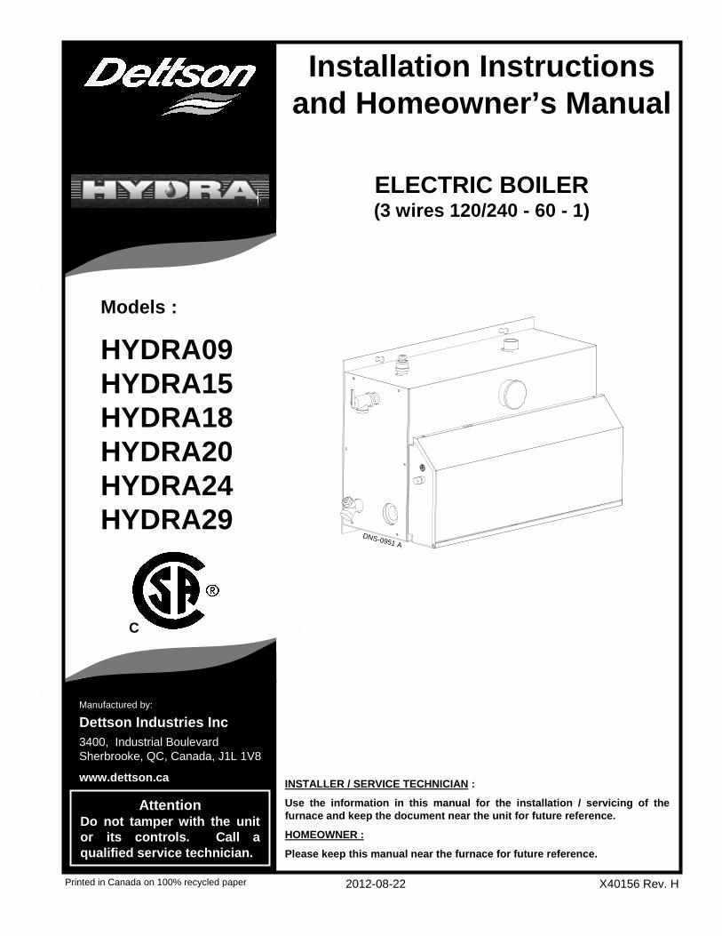
Installation Instructions and Homeowner’s Manual
Printed in Canada on 100% recycled paper 2012-08-22 X40156 Rev. H
Manufactured by:
Dettson Industries Inc
AttentionDo not tamper with the unit or its controls. Call a qualified service technician.
INSTALLER / SERVICE TECHNICIAN :
Use the information in this manual for the installati on / servicing of the furnace and keep the document near the unit for future reference.
HOMEOWNER :
Please keep this manual near the furnace for future refer ence.
ELECTRIC BOILER(3 wires 120/240 - 60 - 1)
Models :
HYDRA09HYDRA15HYDRA18HYDRA20HYDRA24HYDRA29
C
DNS-0951 A
3400, Industrial BoulevardSherbrooke, QC, Canada, J1L 1V8
www.dettson.ca
2
TABLE OF CONTENTS
1.0 SAFETY ................................................................... 3
1.1 DANGER, WARNING AND CAUTION................... 3
1.2 IMPORTANT INFORMATION................................ 3
2.0 INSTALLATION ....................................... ................ 3
2.1 IMPORTANT INFORMATION................................ 3
2.2 DELIVERY ............................................................. 3
2.3 POSITIONING AND CLEARANCES...................... 4
2.4 DANGER OF FREEZING....................................... 4
2.5 DISTRIBUTION SYSTEM ...................................... 4
2.5.1 Freeze protection (when required) .................. 4
2.6 INSTALLATION OF THE BOILER ......................... 4
2.7 ELECTRIC POWER SUPPLY................................ 4
2.7.1 Connecting the circulating pump..................... 5
2.7.2 Connecting the thermostat.............................. 5
2.7.3 Thermostat heat anticipator adjustment (if
required).......................................................... 5
2.7.4 Connecting the outdoor sensor ....................... 5
3.0 OPERATION ............................................................ 5
3.1 ADJUSTMENTS AND START-UP ......................... 5
3.2 CHECKING THE CONTROLS ............................... 6
3.3 BCEH DUAL-ENERGY INSTALLATION................ 6
4.0 MAINTENANCE........................................ ............... 6
4.1 RESPONSIBILITIES .............................................. 6
4.2 PROCEDURE: ....................................................... 7
5.0 FURNACE INFORMATION................................ ...... 7
TABLES Table 1: Minimum Clearance ........................................4
Table 2: Dip Switches Position......................................6
Table 3: HYDRA – Technical Specifications .................9
Table 4: Parts List - HYDRA........................................16
FIGURES
Figure 1: Hydra Electronic Board ...................................5
Figure 2: Boiler water temperature variation according
to outdoor temperature....................................8
Figure 3: Component Identification.................................9
Figure 4: Typical diagram of a single zone
installation .....................................................10
Figure 5: Multizone electrical diagram with more than
one circulator.................................................10
Figure 6: Multiple zones with motorised valve..............11
Figure 7: Electrical Diagram .........................................12
Figure 8: Ladder Diagram ............................................13
Figure 9: Typical diagram of a dual-energy installation
without 3-way valve .......................................14
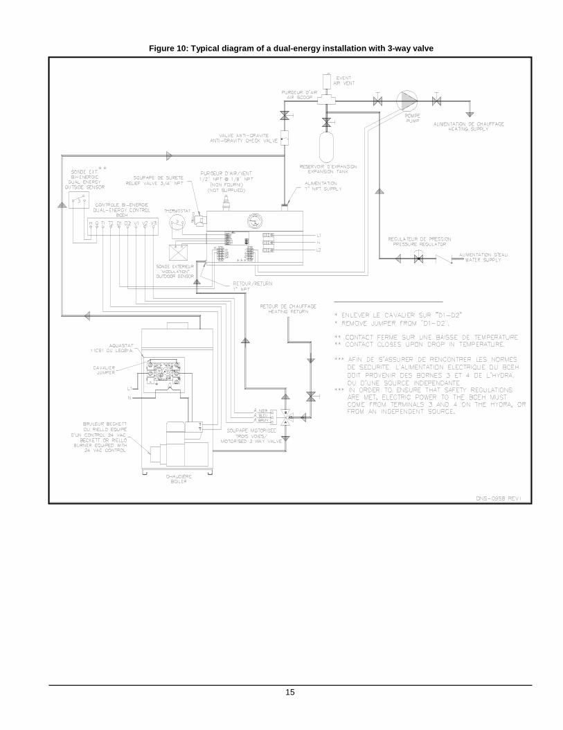
Figure 10: Typical diagram of a dual-energy installation
with 3-way valve............................................15
Figure 11: Parts List - HYDRA........................................16
3
1.0 SAFETY 1.1 DANGER, WARNING AND CAUTION The words DANGER, WARNING and CAUTION are used to identify the levels of seriousness of certain hazards. It is important that you understand their meaning. You will notice these words in the manual as follows:
DANGER
Immediate hazards which WILL result in death or serious bodily and/or material damage.
WARNING
Hazards or unsafe practices which CAN result in dea th or serious bodily and /or material damage.
CAUTION
Hazards or unsafe practices which CAN result in minor bodily and /or material damage.
1.2 IMPORTANT INFORMATION
WARNING
Non-observance of the safety regulations outlined i n this manual will potentially lead to consequences resulting in death, serious bodily injury and/or pr operty damage.
WARNING
Installation and repairs performed by unqualified persons can result in hazards to them and to others . Installations must conform to local codes or, in th e absence of same, to codes of the country having jurisdiction.
The information contained in this manual is intende d for use by a qualified technician, familiar with safety procedures and who is equipped with the proper tool s and test instruments.
Failure to carefully read and follow all instructio ns in this manual can result in death, bodily injury and/ or property damage.
a. It is the homeowner’s responsibility to engage a qualified technician for the installation and subsequent servicing of this boiler;
b. Do not store gasoline or any other flammable substances, such as paper, carton, etc. near the boiler;
c. Ask the technician installing your boiler to sho w and explain to you the main disconnect switch or circui t breaker;
d. Before calling for service, be sure to have the information, section 4, of your manual close by in order to be able to provide the contractor with the required information, such as the model and serial numbers of the boiler.
IMPORTANT: All local and national code requirements governing the installation of Hydronic Heating Systems, wiring and flue connections must be followed. Some of the codes that may be applicable are:
CSA B214-01 Installation Code Hydronic Heating Systems
CSA C22.2 Canadian Electrical Code
Only the latest issues of the above codes should be used, and are available from either:
The Canadian Standards Association 178 Rexdale Blvd. Rexdale, Ontario M9W 1R3
CAUTION
ENVIRONMENTAL HAZARD
Failure to follow this caution may result in environmental pollution.
Remove and recycle all components or materials (i.e . oil, electrical and electronic components, insulati on, etc.) before unit final disposal.
2.0 INSTALLATION 2.1 IMPORTANT INFORMATION Your HYDRA electric boiler was carefully assembled and checked in our plant, so that it will deliver warmth and comfort to your home for many years to come. This manual is intended to provide the necessary information for the installation of the unit, how it functions, and explain security measures which are particular to this type of equipment. It is essential that the persons installing, operating or adjusting the boiler carefully read this manual, in order to completely understand and be familiar with the procedures to be followed. Any questions relative to the operation, maintenance or guarantee should be directed to the company where the equipment was purchased. Upon completion of the installation, this manual should be placed back into its original envelope and kept near the boiler for future reference. 2.2 DELIVERY Upon delivery of the boiler, check the nameplate to be sure that you have received the model with the corr ect rating and proper voltage. The following items are supplied with the unit:
- A pressure relief valve, adjusted to 30 psi;
- A drain valve;
- A ½" NPT to ⅛" NPT reducer for the installation of an air purge valve;
- Modulating outdoor sensor.
4
2.3 POSITIONING AND CLEARANCES The unit must be installed in an area that is dry, non-corrosive, without excessive dust, well ventilated and where the ambient temperature does not exceed 27°C (80°F) . The boiler can be installed directly on a wall, by way of the mounting plate, supplied with the unit. Ensure that it is installed level and that the clearances indicated below are respected (Table 1).
Table 1: Minimum Clearance
LOCATION CLEARANCE
Access side to elements 0.41 m (16") Other side 15.24 cm (6") Above 15.24 cm (6") Front 0.61 m (24") Back 0" 2.4 DANGER OF FREEZING
CAUTION
If your boiler is shut down during the cold weather season, water pipes may freeze, burst and cause serious water damage. Turn off the water supply an d bleed the pipes.
If the heater is left unattended during the cold weather season, take the following precautions:
a. Close the main water valve in the house and purge the pipes if possible. Open all the faucets in the house;
b. Ask someone to frequently check the house during the cold weather season to make sure that there is sufficient heat to prevent the pipes from freezing. Tell this person to call an emergency number if required.
2.5 DISTRIBUTION SYSTEM The proper functioning of your heating system is directly related to the quality of the plumbing installation. Therefore, the entire installation must be performed by qualified technicians. See Figure 3 for the functions of the various boiler connections. The heating system must be set-up to operate at a maximum pressure of 28 psi and the operating temperature may range from 32˚C to 99°C (90˚F to 210°F). 2.5.1 Freeze protection (when required)
WARNING
Only propylene glycol may be used in this hydronic heating system, to prevent freezing.
It is recommended to add a maximum of 50% of propylene glycol mixture to ensure proper operation .
Do not use automotive anti-freeze, ethylene glycol or any undiluted anti-freeze.
If the above recommendations are not followed, seve re personal injury, death or substantial property and/ or equipment damage can result.
All installations must include the following items:
a. 1 pressure regulator, adjusted to 12 psi, installed between the boiler and the main water supply in the building;
b. 1 expansion tank, pre-pressurized to 12 psi and of appropriate size;
c. 1 or more automatic air purge valves;
d. 1 or more circulating pumps of appropriate capacity.
CAUTION
To avoid water damage and/or scalding due to relief valve operation, a discharge line must be connected to the valve outlet and run to a drainage area. The discharge line shall be installed in such a way tha t it will allow for the complete drainage of the valve and th e discharge line.
2.6 INSTALLATION OF THE BOILER At the time of installation, the following steps should be followed. Refer to Figures 3 and 4 for additional information.
1. Choose an appropriate location. Mount the boiler securely on the wall, with the help of the mounting plate. Ensure that it is level and that the minimum clearances are observed;
2. Install the drain valve and the safety valve as indicated in Figure 3;
3. An air vent can be installed on the unit. In such case, use the ½" NPT to ⅛" NPT reducer, which is provided;
4. Install the water supply and and return piping with the 1" NPT fitting;
5. The heating supply line must include:
a. 1 circulator along with 2 maintenance valves;
b. 1 automatic pressure reducing valve adjusted to 12 psi, with a shut-off valve on the return water line;
c. 1 expansion tank;
d. 1 automatic vent.
6. The flow of water through the system must be sufficient to continuously discharge the energy generated by the boiler. If not, a more or less frequent cycling mode will be established by the Safety Control (see the Technical Specifications Table 3;
7. In order to ensure satisfactory water flow, the friction in the piping system must not exceed the capacity of the circulator;
8. After having completed all piping connections, run water through the system and purge the air. The automatic vent should be in operation.
Note: Remove the panel on the right side of the unit and check to see if the elements and the temperature sensor are watertight. 2.7 ELECTRIC POWER SUPPLY All electrical wiring must conform to the standards and regulations in force and the Canadian Electrical Code CSA C22.1. Electrical power to the boiler must come from a 120/240V 60 Hz, single phase, 3-wire, grounded circuit, protected by an
5
appropriately sized breaker, based on the total rating of the boiler. Refer to the boiler nameplate and the technical specifications in this manual, Table 3, to select the proper breaker and determine the wire size.
WARNING
RISK OF FIRE.
The conductor sizing must conform to the last editi on of the local or national codes.
Failure to follow this rule can result in death, bo dily injury and/or property damage.
Power supply to the unit can be made using copper or aluminum wires. The wire size must be decided in accordance to unit power consumption, the over current protection type and capacity, the wire type and length, and the environment where the unit is installed. If an aluminum wire is used, other precautions (such as the use of a DE-OX inhibitor) must be taken to insure the conformity of the installation. In all cases, all the factors affecting the wire gauge must be considered and the installation codes followed. The exterior of the unit must have an uninterrupted ground to minimize the risk of bodily harm. A ground terminal is supplied with the control box for that purpose. In the event that wires inside the unit require replacement, these must be as same type as originals. (Copper wiring only). 2.7.1 Connecting the circulating pump The electronic circuit is designed in such a way that the circulator functions based on demand by the thermostat, or if a high limit condition is detected. Refer to Figure 4 for the connecting of the circulating pump. 2.7.2 Connecting the thermostat Single heating zone
Connect the low voltage thermostat to W1 and R terminals located inside the control panel on the electronic board, as represented on Figure 4. Multiple heating zones
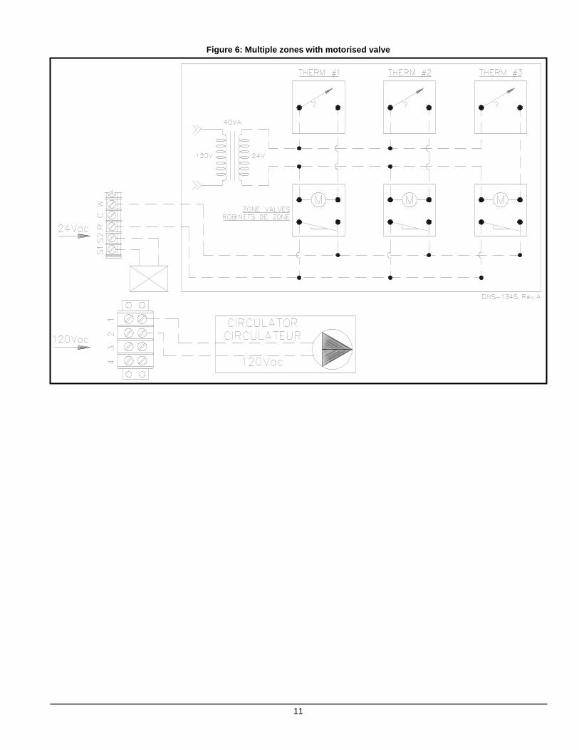
Connect the contacts of the motorized valves or pump controls to W1 and R terminals inside the control panel on the electronic board. See Figures 5 and 6. The anticipator inside the thermostat must be adjusted according to the electrical load connected to the thermostat. 2.7.3 Thermostat heat anticipator adjustment (if
required) Certain thermostats are equipped with a heat anticipator that must be adjusted according to the instructions supplied. This is to ensure that the heating mode is comfortable and economical. Generally speaking, on a single stage thermostat, a reading of the current must be taken with an ammeter as follows:
1. Move the anticipator to its highest setting, rendering it ineffective.
2. Remove the wire from the “W1” terminal and connect an ammeter between the terminal and the wire.
3. Call for heat by raising the set point on the thermostat and allow the boiler to run for 3 to 4 minutes to reach its peak output.
4. Once the current has stabilized, a reading should be taken and the anticipator adjusted to that value. If longer heating cycles are desired, the anticipator can be set to a higher value
2.7.4 Connecting the outdoor sensor Mount the sensor on an outside wall, protected from direct sunlight, so that it will accurately measure the outside temperature. Install 2 only #20 wires between the outdoor sensor and the terminals identified as S1 and S2 on the electronic board terminal.
3.0 OPERATION 3.1 ADJUSTMENTS AND START-UP
CAUTION
The boiler must be filled with water and all air pu rged from the system, before turning on the power.
If the power is turned on before the boiler is fill ed with water, the elements will become seriously damaged a nd the boiler warranty will be void.
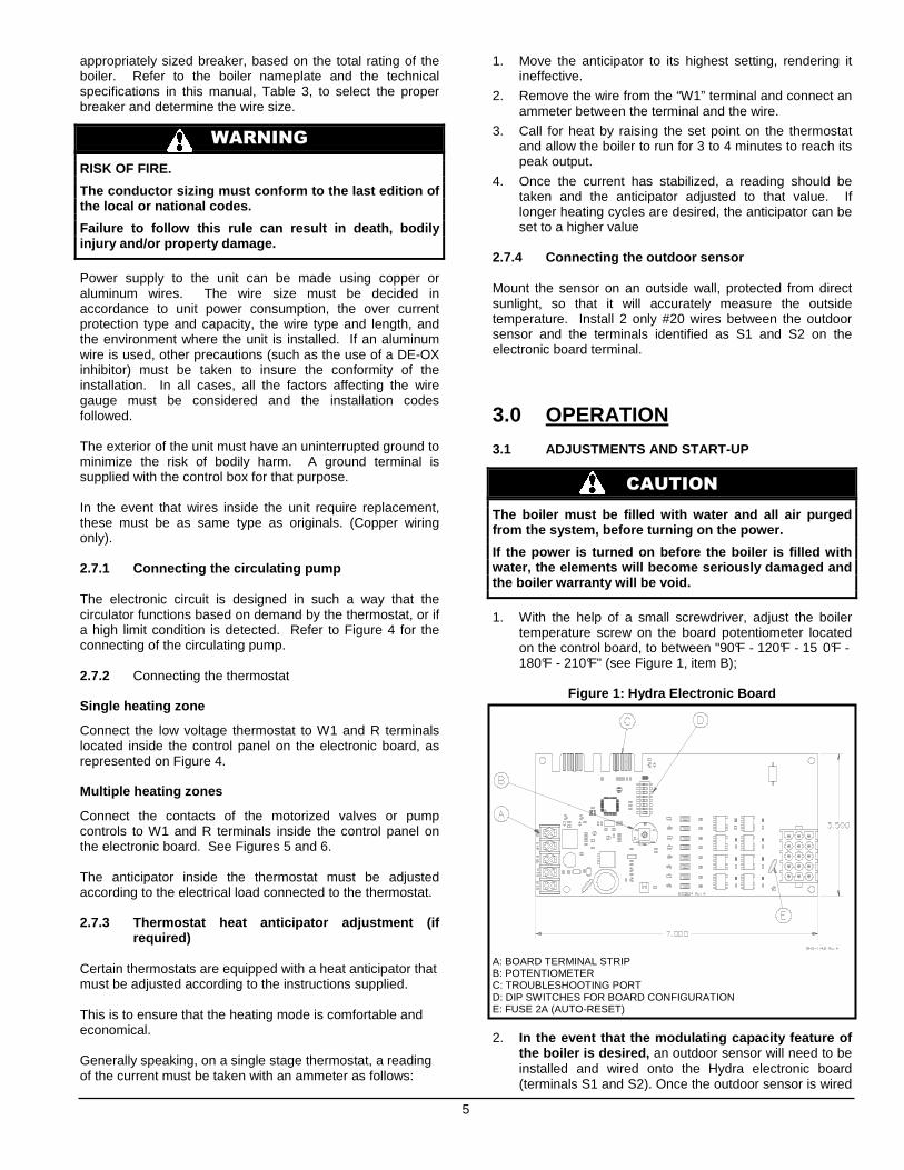
1. With the help of a small screwdriver, adjust the boiler temperature screw on the board potentiometer located on the control board, to between "90°F - 120°F - 15 0°F - 180°F - 210°F" (see Figure 1, item B);
Figure 1: Hydra Electronic Board
A: BOARD TERMINAL STRIP B: POTENTIOMETER C: TROUBLESHOOTING PORT D: DIP SWITCHES FOR BOARD CONFIGURATION E: FUSE 2A (AUTO-RESET)
2. In the event that the modulating capacity feature o f the boiler is desired, an outdoor sensor will need to be installed and wired onto the Hydra electronic board (terminals S1 and S2). Once the outdoor sensor is wired
6
to the board, the boiler capacity will modulate if the outdoor air temperature is between -10˚C (14˚F) and 10˚C (50˚F) (see Figure 2 for more details on modulation). If capacity modulation of the boiler is not required for the application, do not proceed with the installation of the outdoor sensor and leave the terminals S1 and S2 unwired.
3. Check if the dip switches "NUMBER OF ELEMENTS" are in the proper position. Refer to Table 2 and Figure 1, item D to determine the position of the dip switch, based on the power rating;
4. Turn on the power;
5. Adjust room thermostat according to the required temperature.
Table 2: Dip Switches Position
Dip switch 1
Dip switch 2
Dip switch 3
New Hydra with
immersed sensor
OFF ON ON
Number of elements Dip switch 4 Dip switch 5
3 OFF OFF 4 OFF ON 5 ON OFF 6 ON ON
Dip switch 6
Dip switch 7
Dip switch 8
Not used OFF OFF OFF 3.2 CHECKING THE CONTROLS Operational Controls
After having made sure that the boiler is completely filled with water and that there is no call for heat, turn on the power to the unit. For this verification, disconnect the outdoor sensor from the S1 and S2 terminals of the Hydra electronic board. As a result, all the elements will remain functional, regardless of the outside temperature; Set the thermostat in the house to 30°C (85°F). The circulator should start-up and the elements should start sequentially, one by one (randomly), at approximately 15 second intervals. Pilot lights located on the control board provide a visual check of the operation of the boiler;
The circulator stays on for as long as there is a call for heat; By observing the temperature indicator, allow the water temperature to rise to 60°C (140°F). Then, turn the electronic Limit Control counter clockwise to 32°C (90°F). The elements will stop sequentially, one by one, at 1 second intervals between each. Now, the water temperature must be adjusted with the "90°F - 120°F - 150°F - 180°F - 2 10°F" set screw on the electronic board. Once the verification is completed, reconnect the outdoor sensor to S1 and S2 of the Hydra electronic board (if required).
Mechanical High Limit Control
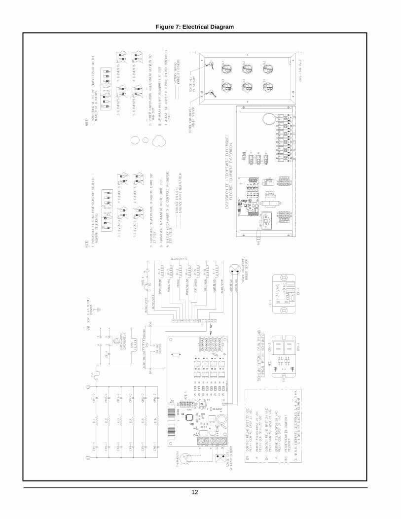
Use the same procedure as outlined in the preceding paragraph, but now on the mechanical aquastat, located at the center left of the control panel (see Figure 7, note 3). This time the elements will all disengage at the same time. The mechanical limit aquastat must be set 20°F abov e the temperature on the electronic board. Modulation Control
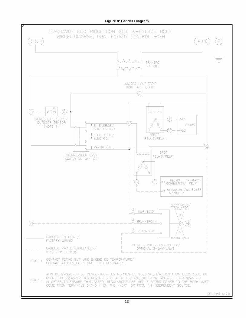
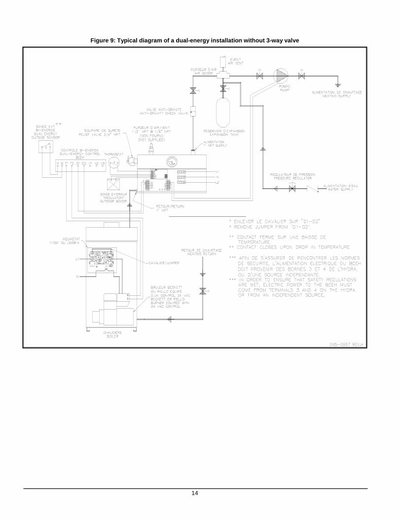
If an outdoor sensor has been installed as specified in section 1.9.4, the overall capacity of your boiler will be reduced upon an increase of the outdoor air temperature as shown on Figure 2. The purpose of this feature is to considerably reduce the number of heating cycles. 3.3 BCEH DUAL-ENERGY INSTALLATION In order to obtain a special rate (DT rate) from your hydro-electric power supplier on residential applications, your HYDRA boiler can be hooked-up to an existing oil heater. Contact your Hydro office to find out if your property is eligible to receive this rate and how to go about obtaining it. BCEH dual-energy controls are specially designed to Hydro standards. The BCEH control selects the least expensive energy source, either oil or electricity, based on outside temperature or a signal from Hydro. The BCEH dual-energy control will start-up the oil burner when the contact in the outdoor dual-energy sensor closes (due to a drop in temperature or other signal), even if the thermostat in the house is not calling for heat. It will stop when the temperature in the boiler reaches its target on the Limit Control. Only in such a case is an anti-gravity valve (flow check valve) or are motorized zone valves required. A three-way motorized valve will direct the water flow either to the oil fired heater or to your electric HYDRA boiler, depending on the signal received from the outdoor dual-energy sensor. To install boiler, refer to Figures 7, 8, 9, and 10 and remove jumper as shown on Figure 7, note 4.
4.0 MAINTENANCE 4.1 RESPONSIBILITIES The property owner has the following responsibilities:
a. To maintain the area around the boiler clean at all times and free from combustible and highly flammable material;
b. To ensure that the ambient air at the boiler is not excessively dusty or humid;
c. To have all water leaks repaired in the system as they arise;
d. To ensure that the ambient temperature in the area where the unit is installed does not exceed 27°C (8 0°F).
It is recommended that the boiler be purged annually, in order to eliminate sediment and sludge that may have accumulated at the bottom of the boiler and covered the heating elements.
7
CAUTION
The boiler warranty may be void if: water leaks in the system are not repaired, the boiler is used as a so urce of domestic hot water or a significant amount of ne w water or air is introduced into the system. 4.2 PROCEDURE: 1. Let the boiler cool down;
2. Close the maintenance valves, which are installed at the water inlet and outlet of the boiler. N.B.: It is not recommended to drain the water from the heating pipe system;
3. Hook-up a garden hose to the drain valve and place it close to a floor drain;
4. Open the purge valve until the water comes out clean and clear;
5. Close the valve. It is recommended to perform a visual inspection of the boiler electrical compartment annually, during the heating season. The items to check are the water tightness of the elements, signs of overheating of the electrical components and the wiring. Corrective measures must be undertaken as required, as soon as possible. Defective components should always be replaced with the Original Equipment Manufacturer’s parts.
5.0 FURNACE INFORMATION Model :
Serial Number :
Installation date of the electric boiler :
Service Telephone # – Day :
Night :
Dealer Name and Address :
8
GRAPH 1 Range of water temperature variation according to p otentiometer adjustment
GRAPH 2 Water temperature variation according to outdoor te mperature
70
90
110
130
150
170
190
210
90 110 130 150 170 190 210Ajustement potentiomètre ( oF)
Potentiometer setpoint ( oF)
Tem
péra
ture
de
l'eau
(oF
)
Wat
er te
mpe
ratu
re (
oF
)
Tmax eauTmax water
Tmin eauTmin water
-15 -10 -5 0 5 10 15
Température extérieure ( oC)
Outdoor air temp ( oC)
Tmax eauTmax water
Tmin eauTmin water
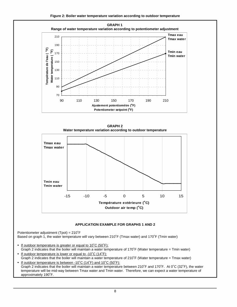
Figure 2: Boiler water temperature variation accord ing to outdoor temperature
APPLICATION EXAMPLE FOR GRAPHS 1 AND 2
Potentiometer adjustment (Tpot) = 210˚F Based on graph 1, the water temperature will vary between 210˚F (Tmax water) and 170˚F (Tmin water) • If outdoor temperature is greater or equal to 10˚C (50˚F): Graph 2 indicates that the boiler will maintain a water temperature of 170˚F (Water temperature = Tmin water) • If outdoor temperature is lower or equal to -10˚C (14˚F):
Graph 2 indicates that the boiler will maintain a water temperature of 210˚F (Water temperature = Tmax water) • If outdoor temperature is between -10˚C (14˚F) and 10˚C (50˚F):
Graph 2 indicates that the boiler will maintain a water temperature between 210˚F and 170˚F. At 0˚C (32˚F), the water temperature will be mid-way between Tmax water and Tmin water. Therefore, we can expect a water temperature of approximately 190˚F.
9
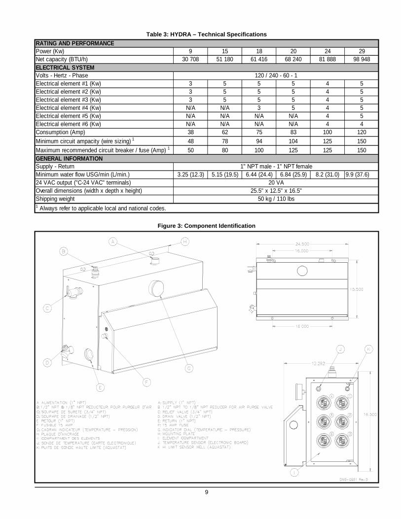
Table 3: HYDRA – Technical Specifications
Figure 3: Component Identification
Power (Kw) 9 15 18 20 24 29Net capacity (BTU/h) 30 708 51 180 61 416 68 240 81 888 98 948
Volts - Hertz - PhaseElectrical element #1 (Kw) 3 5 5 5 4 5Electrical element #2 (Kw) 3 5 5 5 4 5Electrical element #3 (Kw) 3 5 5 5 4 5Electrical element #4 (Kw) N/A N/A 3 5 4 5Electrical element #5 (Kw) N/A N/A N/A N/A 4 5Electrical element #6 (Kw) N/A N/A N/A N/A 4 4Consumption (Amp) 38 62 75 83 100 120
Minimum circuit ampacity (wire sizing) 1 48 78 94 104 125 150
Maximum recommended circuit breaker / fuse (Amp) 1 50 80 100 125 125 150
Supply - ReturnMinimum water flow USG/min (L/min.) 3.25 (12.3) 5.15 (19.5) 6.44 (24.4) 6.84 (25.9) 8.2 (31.0) 9.9 (37.6)24 VAC output ("C-24 VAC" terminals)Overall dimensions (width x depth x height)Shipping weight
RATING AND PERFORMANCE
ELECTRICAL SYSTEM
GENERAL INFORMATION1" NPT male - 1" NPT female
20 VA25.5" x 12.5" x 16.5"
50 kg / 110 lbs
120 / 240 - 60 - 1
1 Always refer to applicable local and national codes.
10
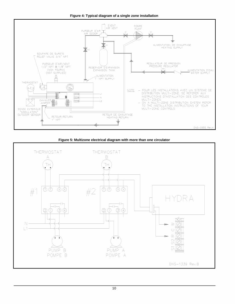
Figure 4: Typical diagram of a single zone installa tion
Figure 5: Multizone electrical diagram with more th an one circulator
11
Figure 6: Multiple zones with motorised valve
12
Figure 7: Electrical Diagram
13
Figure 8: Ladder Diagram 3
14
Figure 9: Typical diagram of a dual-energy installa tion without 3-way valve
15
Figure 10: Typical diagram of a dual-energy instal lation with 3-way valve
16
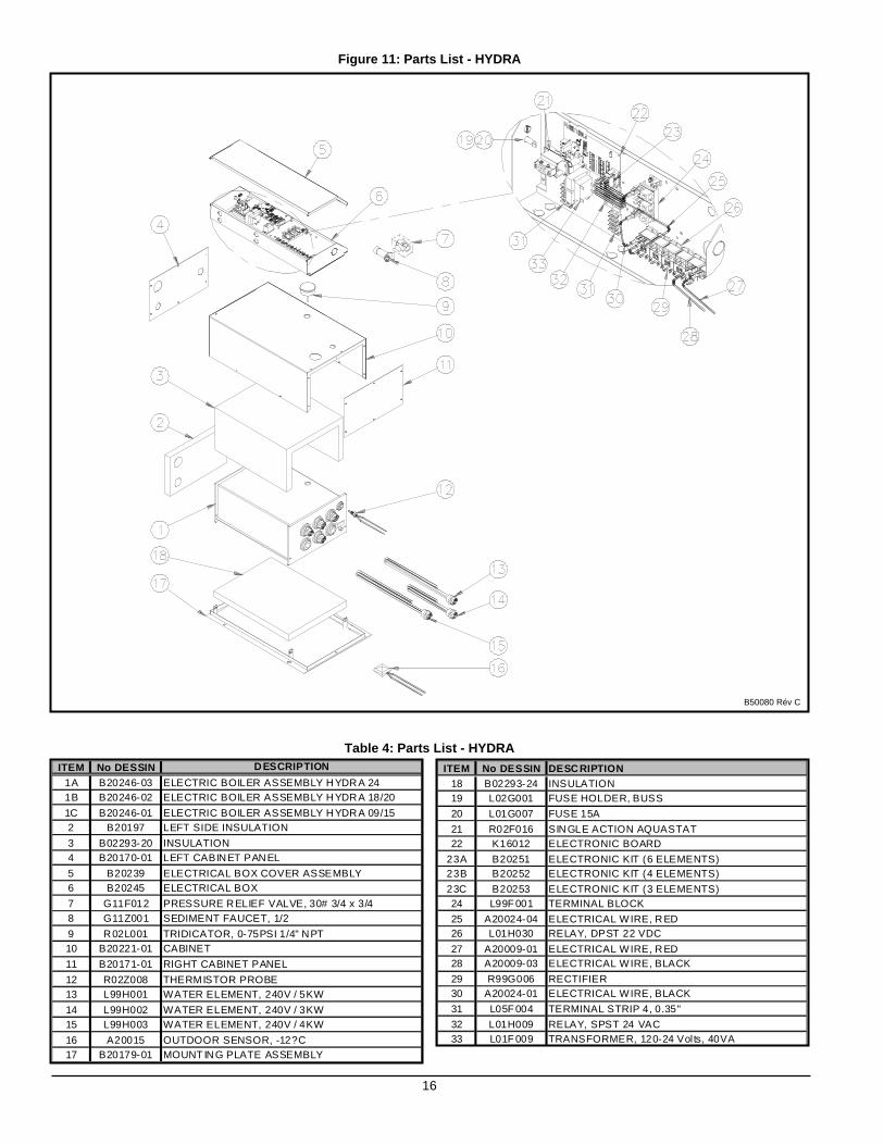
Figure 11: Parts List - HYDRA
Table 4: Parts List - HYDRA ITEM No DESSIN DESCRIPTION
1A B20246-03 ELECTRIC BOILER ASSEMBLY HYDRA 241B B20246-02 ELECTRIC BOILER ASSEMBLY HYDRA 18/20
1C B20246-01 ELECTRIC BOILER ASSEMBLY HYDRA 09/152 B20197 LEFT SIDE INSULATION
3 B02293-20 INSULATION4 B20170-01 LEFT CABINET PANEL
5 B20239 ELECTRICAL BOX COVER ASSEMBLY6 B20245 ELECTRICAL BOX
7 G11F012 PRESSURE RELIEF VALVE, 30# 3/4 x 3/48 G11Z001 SEDIMENT FAUCET, 1/2
9 R02L001 TRIDICATOR, 0-75PSI 1/4" NPT10 B20221-01 CABINET
11 B20171-01 RIGHT CABINET PANEL
12 R02Z008 THERMISTOR PROBE13 L99H001 WATER ELEMENT, 240V / 5KW
14 L99H002 WATER ELEMENT, 240V / 3KW15 L99H003 WATER ELEMENT, 240V / 4KW
16 A20015 OUTDOOR SENSOR, -12?C17 B20179-01 MOUNT ING PLATE ASSEMBLY
B50080 Rév C
ITEM No DESSIN DESCRIPTION18 B02293-24 INSULATION19 L02G001 FUSE HOLDER, BUSS
20 L01G007 FUSE 15A
21 R02F016 SINGLE ACTION AQUASTAT22 K16012 ELECTRONIC BOARD
23A B20251 ELECTRONIC KIT (6 ELEMENTS)23B B20252 ELECTRONIC KIT (4 ELEMENTS)
23C B20253 ELECTRONIC KIT (3 ELEMENTS)24 L99F 001 TERMINAL BLOCK
25 A20024-04 ELECTRICAL WIRE, RED26 L01H030 RELAY, DPST 22 VDC
27 A20009-01 ELECTRICAL WIRE, RED28 A20009-03 ELECTRICAL WIRE, BLACK
29 R99G006 RECTIFIER30 A20024-01 ELECTRICAL WIRE, BLACK
31 L05F 004 TERMINAL STRIP 4, 0.35"
32 L01H009 RELAY, SPST 24 VAC33 L01F 009 TRANSFORMER, 120-24 Volts, 40VA