Embed Size (px)
Citation preview
507324-01 Page 1 of 32Issue 1623
This is a safety alert symbol and should never be ignored. When you see this symbol on labels or in manuals, be alert to the potential for personal injury or death.
As with any mechanical equipment, personal injury can result from contact with sharp sheet metal edges. Be careful when you handle this equipment.
CAUTIONImproper installation, adjustment, alteration, service or maintenance can cause property damage, personal injury or loss of life. Installation and service must be performed by a licensed professional installer (or equivalent), service agency or the gas supplier.
WARNING
Manufactured ByAllied Air Enterprises LLC
A Lennox International, Inc. Company215 Metropolitan Drive
West Columbia, SC 29170
This manual must be left with the homeowner for future reference.
INSTALLATION INSTRUCTIONSA80UH & 80G1UH
Warm Air Gas Furnace Upflow / Horizontal Left and Right Air Discharge
(P) 507324-01
*P507324-01*
Table of Contents
Unit Dimensions ......................................................................2A80UH & 80G1UH Gas Furnace .............................................3Shipping and Packing List .......................................................3Safety Information ...................................................................3Use of Furnace as a Construction Heater ...............................4General ....................................................................................5Combustion, Dilution & Ventilation Air .....................................5Setting Equipment ...................................................................8Filters .....................................................................................11Duct System ..........................................................................11
Venting...................................................................................12Gas Piping .............................................................................19Electrical ................................................................................21Unit Start-Up ..........................................................................25Heating Sequence Of Operation ..........................................26Gas Pressure Adjustment .....................................................26High Altitude ..........................................................................27Other Unit Adjustments..........................................................28Service...................................................................................29Repair Parts List ....................................................................30
507324-01Page 2 of 32 Issue 1623
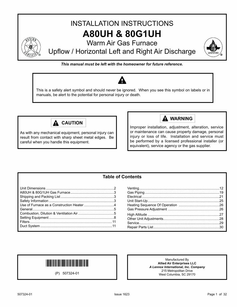
A80UH & 80G1UH Unit Dimensions - inches (mm)
1 NOTE - 20C and 20D size units installed in upflow applications that require air volumes of 1800 cfm (850 L/s or greater must have one of the following: 1. Single side return air with transition, to accommodate 20 x 25 x 1 in. (508 x 635 x 25 mm) air filter. 2. Single side return air with optional RAB Return Air Base 3. Bottom return air. 4. Return air from both sides. 5. Bottom and one side return air.2 Flue outlet may be horizontal but furnace must be vented vertically.3 Optional external side return air filter kit cannot be used with the optional RAB Return Air Base.
* Consider sizing requirements for optional IAQ equipment before cutting side return opening.
FRONT VIEW SIDE VIEW
507324-01 Page 3 of 32Issue 1623
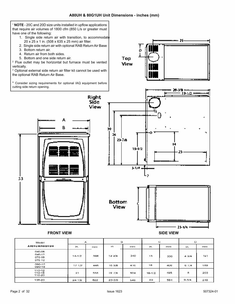
A80UH & 80G1UH Gas FurnaceThe A80UH & 80G1UH gas furnace is shipped ready for installation in the upflow or horizontal right position (for horizontal left position the combustion air pressure switch must be moved). The furnace is shipped with the bottom panel in place. The bottom panel must be removed if the unit is to be installed in horizontal or upflow applications with bottom return air.
The furnace is equipped for installation in natural gas applications. A conversion kit (ordered separately) is required for use in propane/LP gas applications.
Shipping and Packing List1 - Assembled Gas Furnace1 - Bag assembly containing the following: 2 - Screws 3 - Wire nuts 1 - Snap bushing 1 - Snap Plug 1 - Wire tie 1 - Vent warning label 1 - Owner’s manual and warranty card
Check equipment for shipping damage. If you find any damage, immediately contact the last carrier.
Safety Information
As with any mechanical equipment, personal injury can result from contact with sharp sheet metal edges. Be careful when you handle this equipment.
CAUTION
DANGER OF EXPLOSION!
DANGER
There are circumstances in which odorant used with LP/Propane gas can lose its scent. In case of a leak, LP/Propane gas will settle close to the floor and may be difficult to smell. An LP/Propane leak detector should be installed in all LP applications.
Improper installation, adjustment, alteration, service or maintenance can cause property damage, personal injury or loss of life. Installation and service must be performed by a licensed professional installer (or equivalent), service agency or the gas supplier.
WARNING
CertificationsThese units are CSA International certified to ANSI Z21.47.
In the USA, installation of gas furnaces must conform with local building codes. In the absence of local codes, units must be installed according to the current National Fuel Gas Code (ANSI-Z223.1). The National Fuel Gas Code is available from the following address: American National Standards Institute, Inc., 11 West 42nd Street, New York, NY 10036.
ClearancesAdequate clearance must be made around the air openings into the vestibule area. In order to ensure proper unit operation, combustion and ventilation air supply must be provided according to the current National Fuel Gas Code. Vent installations must be consistent with the venting tables (in this instruction) and applicable provisions of local building codes.
This furnace is CSA International certified for installation clearances to combustible material as listed on the unit nameplate and in the tables in Figures 8 and 12. Accessibility and service clearances must take precedence over fire protection clearances.
Installed LocationsFor installation in a residential garage, the furnace must be installed so that the burner(s) and the ignition source are located no less than 18 inches (457 mm) above the floor. The furnace must be located or protected to avoid physical damage by vehicles. When a furnace is installed in a public garage, hangar, or other building that has a hazardous atmosphere, the furnace must be installed according to recommended good practice requirements and current National Fuel Gas Code.
Please refer to specification sheets for available accessories.
507324-01Page 4 of 32 Issue 1623
Temperature Rise
NOTE: Furnace must be adjusted to obtain a temperature rise within the range specified on the unit nameplate. Failure to do so may cause erratic limit operation and may result in premature heat exchanger failure.
This furnace must be installed so that its electrical components are protected from water.
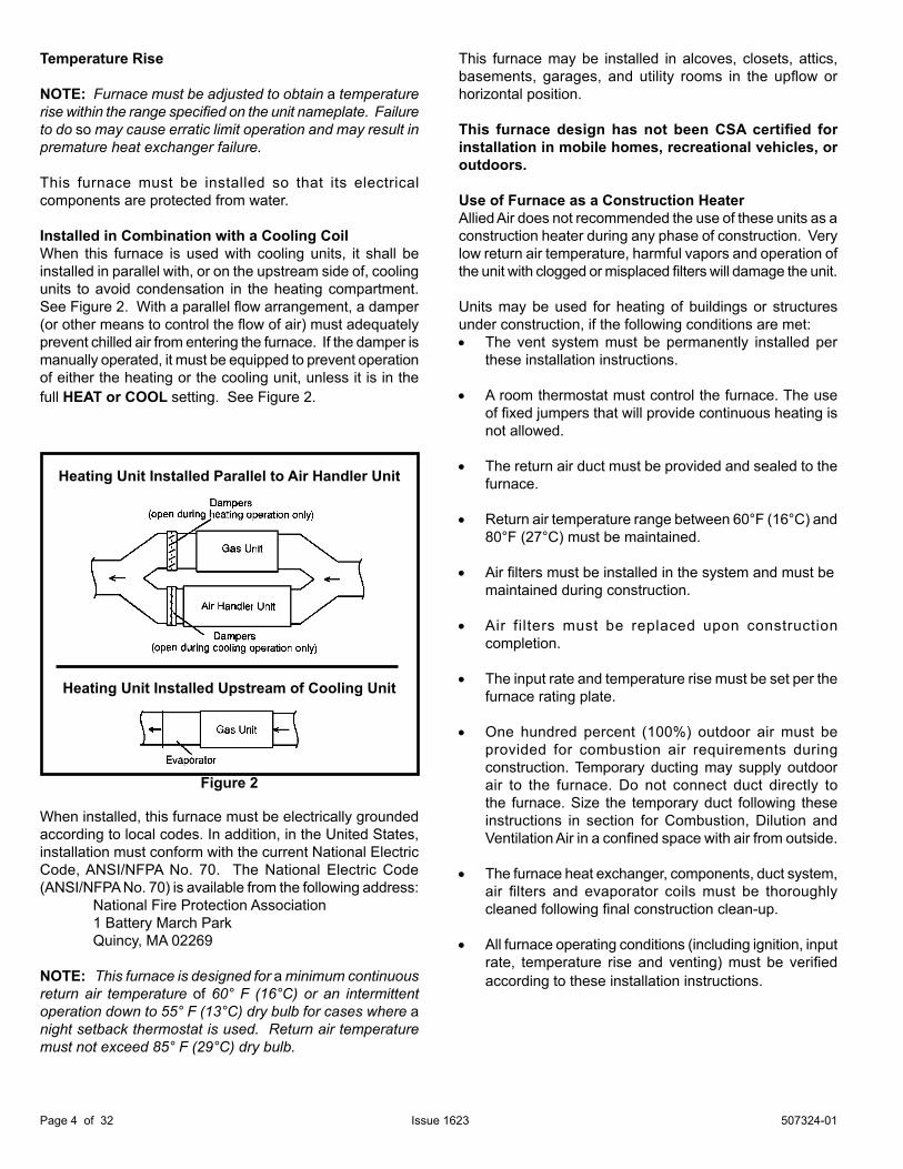
Installed in Combination with a Cooling CoilWhen this furnace is used with cooling units, it shall be installed in parallel with, or on the upstream side of, cooling units to avoid condensation in the heating compartment. See Figure 2. With a parallel flow arrangement, a damper (or other means to control the flow of air) must adequately pre vent chilled air from entering the furnace. If the damper is manually operated, it must be equipped to prevent operation of either the heating or the cooling unit, unless it is in the full HEAT or COOL setting. See Figure 2.
Figure 2
Heating Unit Installed Parallel to Air Handler Unit
Heating Unit Installed Upstream of Cooling Unit
This furnace may be installed in alcoves, closets, attics, basements, garages, and utility rooms in the upflow or horizontal position.
This furnace design has not been CSA certified for installation in mobile homes, recreational vehicles, or outdoors.
Use of Furnace as a Construction HeaterAllied Air does not recommended the use of these units as a construction heater during any phase of construction. Very low return air temperature, harmful vapors and operation of the unit with clogged or misplaced filters will damage the unit.
Units may be used for heating of buildings or structures under construction, if the following conditions are met:• The vent system must be permanently installed per
these installation instructions.
• A room thermostat must control the furnace. The use of fixed jumpers that will provide continuous heating is not allowed.
• The return air duct must be provided and sealed to the furnace.
• Return air temperature range between 60°F (16°C) and 80°F (27°C) must be maintained.
• Air filters must be installed in the system and must be maintained during construction.
• Air filters must be replaced upon construction completion.
• The input rate and temperature rise must be set per the furnace rating plate.
• One hundred percent (100%) outdoor air must be provided for combustion air requirements during construction. Temporary ducting may supply outdoor air to the furnace. Do not connect duct directly to the furnace. Size the temporary duct following these instructions in section for Combustion, Dilution and Ventilation Air in a confined space with air from outside.
• The furnace heat exchanger, components, duct system, air filters and evaporator coils must be thoroughly cleaned following final construction clean-up.
• All furnace operating conditions (including ignition, input rate, temperature rise and venting) must be verified according to these installation instructions.
When installed, this furnace must be electrically grounded according to local codes. In addition, in the United States, installation must conform with the current National Electric Code, ANSI/NFPA No. 70. The National Electric Code (ANSI/NFPA No. 70) is available from the following address: National Fire Protection Association 1 Battery March Park Quincy, MA 02269
NOTE: This furnace is designed for a minimum continuous return air temperature of 60° F (16°C) or an intermittent operation down to 55° F (13°C) dry bulb for cases where a night setback thermostat is used. Return air temperature must not exceed 85° F (29°C) dry bulb.
507324-01 Page 5 of 32Issue 1623
GeneralThese instructions are intended as a general guide and do not supersede local codes in any way. Consult authorities having jurisdiction before installation.
In addition to the requirements outlined previously, the following general recommendations must be considered when installing one of these furnaces:
• Place the furnace as close to the center of the air distribution system as possible. The furnace should also be located close to the chimney or vent termination point.
• Do not install the furnace where drafts might blow directly into it. This could cause improper combustion.
• Do not block the furnace combustion air openings with clothing, boxes, doors, etc. Air is needed for proper combustion and safe unit operation.
• When the furnace is installed in an attic or other insulated space, keep insulation away from the furnace.
NOTE: The Commonwealth of Massachusetts stipulates these additional requirements:
• Gas furnaces shall be installed by a licensed plumber or fitter only.
• The gas cock must be “T handle” type.• When a furnace is installed in an attic, the passageway
to and service area surrounding the equipment shall be floored.
Combustion, Dilution & Ventilation AirIn the past, there was no problem in bringing in sufficient outdoor air for combustion. Infiltration provided all the air that was needed. In today’s homes, tight construction practices make it necessary to bring in air from outside for combustion. Take into account that exhaust fans, appliance vents, chimneys, and fireplaces force additional air that could be used for combustion out of the house. Unless outside air is brought into the house for combustion, negative pressure (outside pressure is greater than inside pressure) will build to the point that a downdraft can occur in the furnace vent pipe or chimney. As a result, combustion gases enter the living space creating a potentially dangerous situation.
In the absence of local codes concerning air for combustion and ventilation, use the guidelines and procedures in this section to install these furnaces to ensure efficient and safe operation. You must consider combustion air needs and requirements for exhaust vents and gas piping.
A portion of this information has been reprinted with permission from the National Fuel Gas Code (ANSI-Z223.1). This reprinted material is not the complete and official position of the ANSI on the referenced subject, which is represented only by the standard in its entirety.
Insufficient combustion air can cause headaches, nausea, dizziness or asphyxiation. It will also cause excess water in the heat exchanger resulting in rusting and premature heat exchanger failure. Excessive exposure to contaminated combustion air will result in safety and performance related problems. Avoid exposure to the following substances in the combustion air supply: Permanent wave solutions Chlorinated waxes and cleaners Chlorine base swimming pool chemicals Water softening chemicals De-icing salts or chemicals Carbon tetrachloride Halogen type refrigerants Cleaning solvents (such as perchloroethylene) Printing inks, paint removers, varnishes, etc. Hydrochloric acid Antistatic fabric softeners for clothes dryers Masonry acid washing materials
WARNING
The State of California has determined that this product may contain or produce a chemical or chemicals, in very low doses, which may cause serious illness or death. It may also cause cancer, birth defects or other reproductive harm.
WARNING
507324-01Page 6 of 32 Issue 1623
All gas fired appliances require air for the combustion process. If sufficient combustion air is not available, the furnace or other appliances will operate inefficiently and unsafely. Enough air must be provided to meet the needs of all fuel burning appliances and appliances such as exhaust fans which force air out of the house. When fireplaces, exhaust fans, or clothes dryers are used at the same time as the furnace, much more air is necessary to ensure proper combustion and to prevent a downdraft. Insufficient air causes incomplete combustion which can result in carbon monoxide.
In addition to providing combustion air, fresh outdoor air dilutes contaminants in the indoor air. These contaminants may include bleaches, adhesives, detergents, solvents and other contaminants which can corrode furnace components.
The requirements for providing air for combustion and ventilation depend largely on whether the furnace is installed in an unconfined or a confined space.
Unconfined SpaceAn unconfined space is an area such as a basement or large equipment room with a volume greater than 50 cubic feet (1.42 m3) per 1,000 Btu (.29 kW) per hour of the combined input rating of all appliances installed in that space. This space also includes adjacent rooms which are not separated by a door. Though an area may appear to be unconfined, it might be necessary to bring in outdoor air for combustion if the structure does not provide enough air by infiltration. If the furnace is located in a building of tight construction with weather stripping and caulking around the windows and doors, follow the procedures in the air from outside section.
Confined SpaceA confined space is an area with a volume less than 50 cubic feet (1.42 m3) per 1,000 Btu (.29 kW) per hour of the combined input rating of all appliances installed in that space. This definition includes furnace closets or small equipment rooms.
When the furnace is installed so that supply ducts carry air circulated by the furnace to areas outside the space containing the furnace, the return air must be handled by ducts which are sealed to the furnace casing and which terminate outside the space containing the furnace. This is especially important when the furnace is mounted on a platform in a confined space such as a closet or small equipment room. Even a small leak around the base of the unit at the platform or at the return air duct connection can cause a potentially dangerous negative pressure condition. Air for combustion and ventilation can be brought into the confined space either from inside the building or from outside.
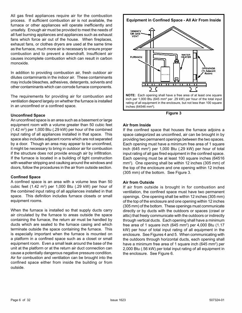
Air from InsideIf the confined space that houses the furnace adjoins a space categorized as unconfined, air can be brought in by providing two permanent openings between the two spaces. Each opening must have a minimum free area of 1 square inch (645 mm2) per 1,000 Btu (.29 kW) per hour of total input rating of all gas fired equipment in the confined space. Each opening must be at least 100 square inches (64516 mm2). One opening shall be within 12 inches (305 mm) of the top of the enclosure and one opening within 12 inches (305 mm) of the bottom. See Figure 3.
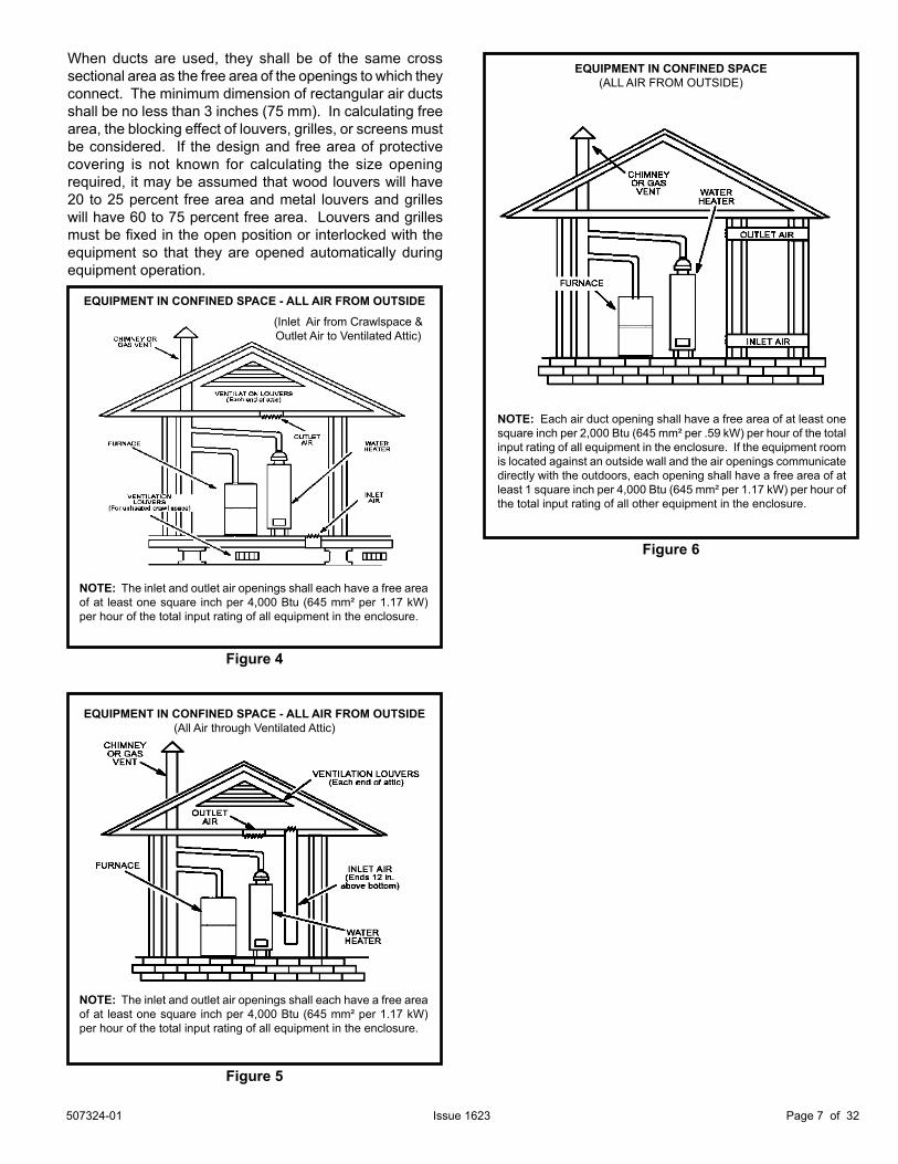
Air from OutsideIf air from outside is brought in for combustion and ventilation, the confined space must have two permanent openings. One opening shall be within 12 inches (305 mm) of the top of the enclosure and one opening within 12 inches (305 mm) of the bottom. These openings must communicate directly or by ducts with the outdoors or spaces (crawl or attic) that freely communicate with the outdoors or indirectly through vertical ducts. Each opening shall have a minimum free area of 1 square inch (645 mm2) per 4,000 Btu (1.17 kW) per hour of total input rating of all equipment in the enclosure. See Figures 4 and 5. When communicating with the outdoors through horizontal ducts, each opening shall have a minimum free area of 1 square inch (645 mm2) per 2,000 Btu (.56 kW) per total input rating of all equipment in the enclosure. See Figure 6.
Figure 3
Equipment in Confined Space - All Air From Inside
NOTE: Each opening shall have a free area of at least one square inch per 1,000 Btu (645 mm² per .29 kW) per hour of the total input rating of all equipment in the enclosure, but not less than 100 square inches (64546 mm²).
507324-01 Page 7 of 32Issue 1623
When ducts are used, they shall be of the same cross sectional area as the free area of the openings to which they connect. The minimum dimension of rectangular air ducts shall be no less than 3 inches (75 mm). In calculating free area, the blocking effect of louvers, grilles, or screens must be considered. If the design and free area of protective covering is not known for calculating the size opening required, it may be assumed that wood louvers will have 20 to 25 percent free area and metal louvers and grilles will have 60 to 75 percent free area. Louvers and grilles must be fixed in the open position or interlocked with the equipment so that they are opened automatically during equipment operation.
EQUIPMENT IN CONFINED SPACE(ALL AIR FROM OUTSIDE)
NOTE: Each air duct opening shall have a free area of at least one square inch per 2,000 Btu (645 mm² per .59 kW) per hour of the total input rating of all equipment in the enclosure. If the equipment room is located against an outside wall and the air openings communicate directly with the outdoors, each opening shall have a free area of at least 1 square inch per 4,000 Btu (645 mm² per 1.17 kW) per hour of the total input rating of all other equipment in the enclosure.
Figure 6
Figure 4
EQUIPMENT IN CONFINED SPACE - ALL AIR FROM OUTSIDE
NOTE: The inlet and outlet air openings shall each have a free area of at least one square inch per 4,000 Btu (645 mm² per 1.17 kW) per hour of the total input rating of all equipment in the enclosure.
(Inlet Air from Crawlspace & Outlet Air to Ventilated Attic)
EQUIPMENT IN CONFINED SPACE - ALL AIR FROM OUTSIDE(All Air through Ventilated Attic)
NOTE: The inlet and outlet air openings shall each have a free area of at least one square inch per 4,000 Btu (645 mm² per 1.17 kW) per hour of the total input rating of all equipment in the enclosure.
Figure 5
507324-01Page 8 of 32 Issue 1623
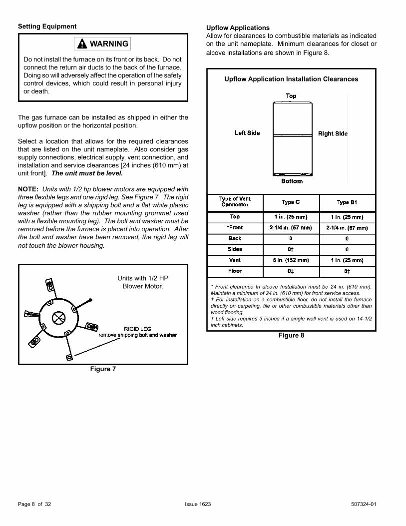
The gas furnace can be installed as shipped in either the upflow position or the horizontal position.
Select a location that allows for the required clearances that are listed on the unit nameplate. Also consider gas supply connections, electrical supply, vent connection, and installation and service clearances [24 inches (610 mm) at unit front]. The unit must be level.
NOTE: Units with 1/2 hp blower motors are equipped with three flexible legs and one rigid leg. See Figure 7. The rigid leg is equipped with a shipping bolt and a flat white plastic washer (rather than the rubber mounting grommet used with a flexible mounting leg). The bolt and washer must be removed before the furnace is placed into operation. After the bolt and washer have been removed, the rigid leg will not touch the blower housing.
Setting Equipment
WARNING
Do not install the furnace on its front or its back. Do not connect the return air ducts to the back of the furnace. Doing so will adversely affect the operation of the safety control devices, which could result in personal injury or death.
Upflow ApplicationsAllow for clearances to combustible materials as indicated on the unit nameplate. Minimum clearances for closet or alcove installations are shown in Figure 8.
Figure 8
Upflow Application Installation Clearances
* Front clearance In alcove Installation must be 24 in. (610 mm). Maintain a minimum of 24 in. (610 mm) for front service access. ‡ For installation on a combustible floor, do not install the furnace directly on carpeting, tile or other combustible materials other than wood flooring.† Left side requires 3 inches if a single wall vent is used on 14-1/2 inch cabinets.
Figure 7
Units with 1/2 HP Blower Motor.
507324-01 Page 9 of 32Issue 1623
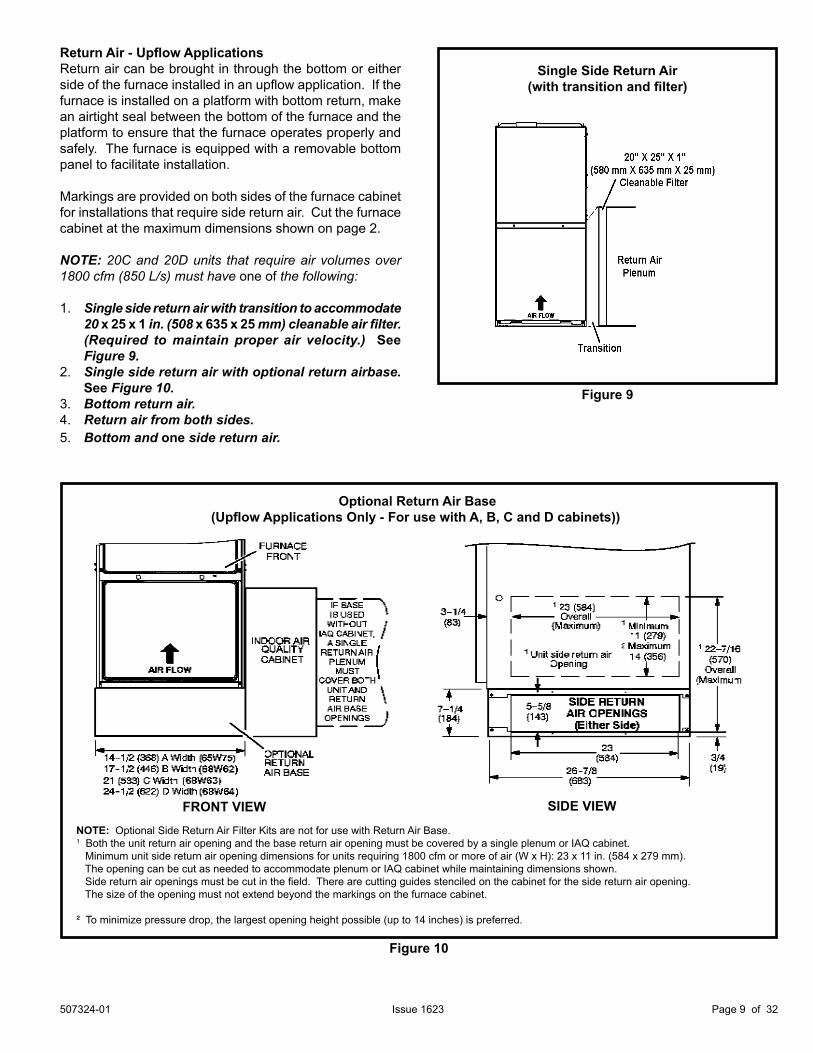
Return Air - Upflow ApplicationsReturn air can be brought in through the bottom or either side of the furnace installed in an upflow application. If the furnace is installed on a platform with bottom return, make an airtight seal between the bottom of the furnace and the platform to ensure that the furnace operates properly and safely. The furnace is equipped with a removable bottom panel to facilitate installation.
Markings are provided on both sides of the furnace cabinet for installations that require side return air. Cut the furnace cabinet at the maximum dimensions shown on page 2.
NOTE: 20C and 20D units that require air volumes over 1800 cfm (850 L/s) must have one of the following:
1. Single side return air with transition to accommodate 20 x 25 x 1 in. (508 x 635 x 25 mm) cleanable air filter. (Required to maintain proper air velocity.) See Figure 9.
2. Single side return air with optional return airbase. See Figure 10.
3. Bottom return air.4. Return air from both sides.5. Bottom and one side return air.
Figure 9
Single Side Return Air(with transition and filter)
Optional Return Air Base(Upflow Applications Only - For use with A, B, C and D cabinets))
NOTE: Optional Side Return Air Filter Kits are not for use with Return Air Base.1 Both the unit return air opening and the base return air opening must be covered by a single plenum or IAQ cabinet. Minimum unit side return air opening dimensions for units requiring 1800 cfm or more of air (W x H): 23 x 11 in. (584 x 279 mm). The opening can be cut as needed to accommodate plenum or IAQ cabinet while maintaining dimensions shown. Side return air openings must be cut in the field. There are cutting guides stenciled on the cabinet for the side return air opening. The size of the opening must not extend beyond the markings on the furnace cabinet.
² To minimize pressure drop, the largest opening height possible (up to 14 inches) is preferred.
FRONT VIEW
Figure 10
SIDE VIEW
507324-01Page 10 of 32 Issue 1623
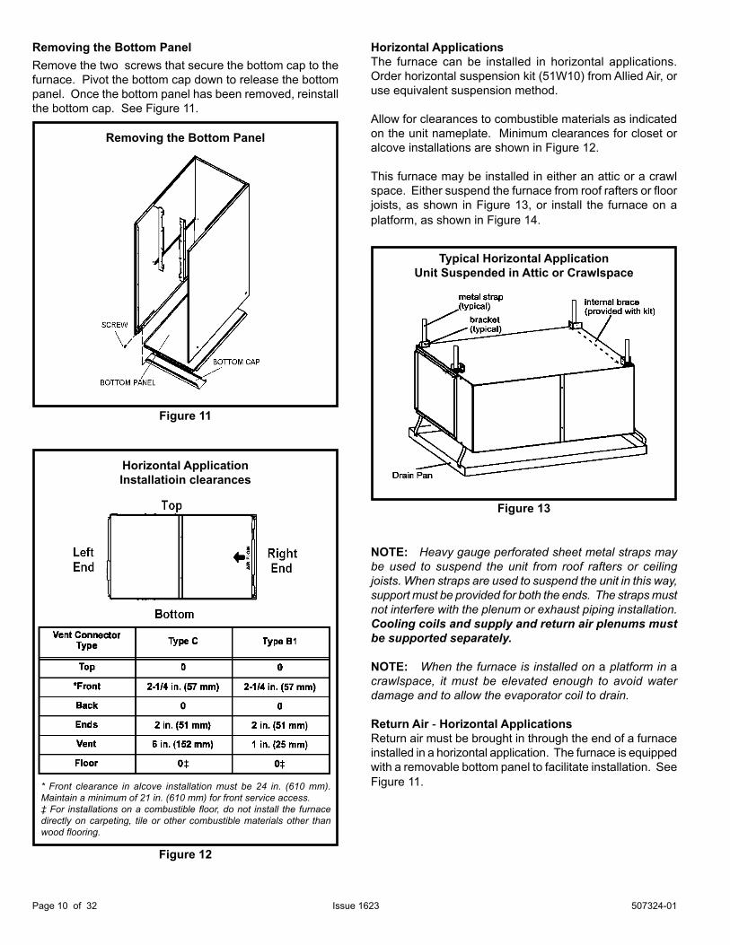
Removing the Bottom PanelRemove the two screws that secure the bottom cap to the furnace. Pivot the bottom cap down to release the bottom panel. Once the bottom panel has been removed, reinstall the bottom cap. See Figure 11.
Horizontal ApplicationsThe furnace can be installed in horizontal applications. Order horizontal suspension kit (51W10) from Allied Air, or use equivalent suspension method.
Allow for clearances to combustible materials as indicated on the unit nameplate. Minimum clearances for closet or alcove installations are shown in Figure 12.
This furnace may be installed in either an attic or a crawl space. Either suspend the furnace from roof rafters or floor joists, as shown in Figure 13, or install the furnace on a platform, as shown in Figure 14.
NOTE: Heavy gauge perforated sheet metal straps may be used to suspend the unit from roof rafters or ceiling joists. When straps are used to suspend the unit in this way, support must be provided for both the ends. The straps must not interfere with the plenum or exhaust piping installation. Cooling coils and supply and return air plenums must be supported separately.
NOTE: When the furnace is installed on a platform in a crawlspace, it must be elevated enough to avoid water damage and to allow the evaporator coil to drain.
Return Air - Horizontal ApplicationsReturn air must be brought in through the end of a furnace installed in a horizontal application. The furnace is equipped with a removable bottom panel to facilitate installation. See Figure 11.
Horizontal ApplicationInstallatioin clearances
* Front clearance in alcove installation must be 24 in. (610 mm). Maintain a minimum of 21 in. (610 mm) for front service access.‡ For installations on a combustible floor, do not install the furnace directly on carpeting, tile or other combustible materials other than wood flooring.
Figure 12
Figure 11
Removing the Bottom Panel
Typical Horizontal ApplicationUnit Suspended in Attic or Crawlspace
Figure 13
507324-01 Page 11 of 32Issue 1623
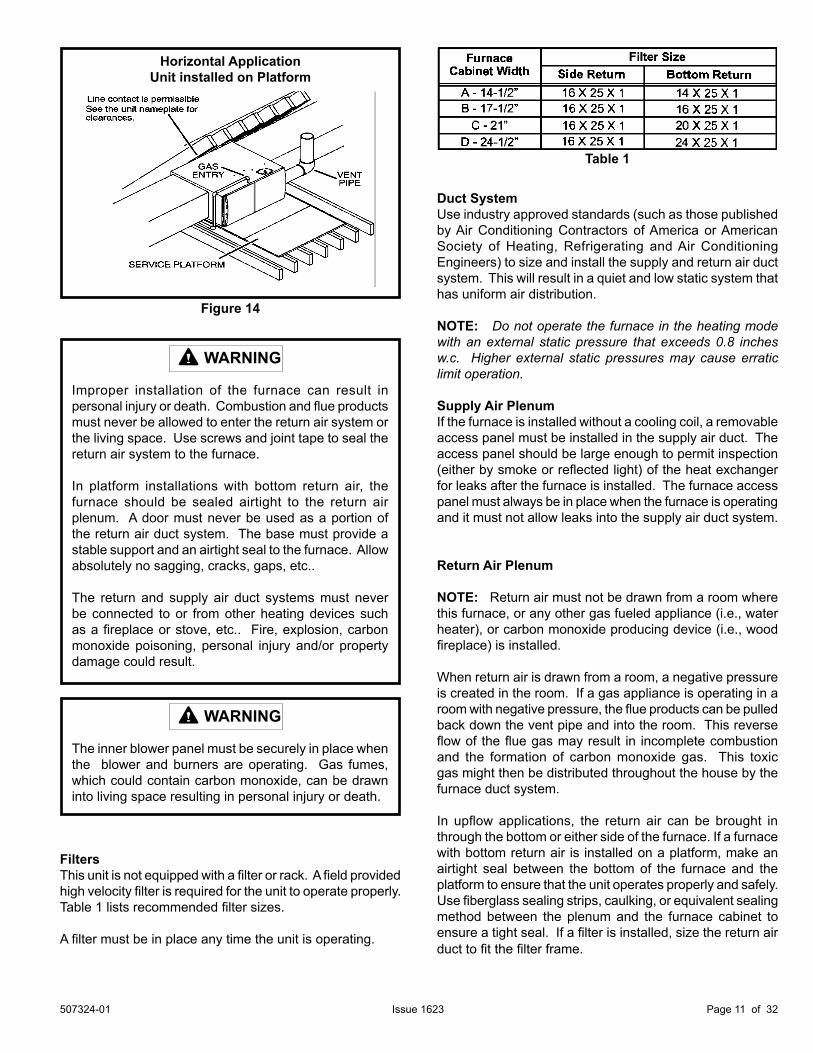
FiltersThis unit is not equipped with a filter or rack. A field provided high velocity filter is required for the unit to operate properly. Table 1 lists recommended filter sizes.
A filter must be in place any time the unit is operating.
Duct SystemUse industry approved standards (such as those published by Air Conditioning Contractors of America or American Society of Heating, Refrigerating and Air Conditioning Engineers) to size and install the supply and return air duct system. This will result in a quiet and low static system that has uniform air distribution.
NOTE: Do not operate the furnace in the heating mode with an external static pressure that exceeds 0.8 inches w.c. Higher external static pressures may cause erratic limit operation.
Supply Air PlenumIf the furnace is installed without a cooling coil, a removable access panel must be installed in the supply air duct. The access panel should be large enough to permit inspection (either by smoke or reflected light) of the heat exchanger for leaks after the furnace is installed. The furnace access panel must always be in place when the furnace is operating and it must not allow leaks into the supply air duct system.
Return Air Plenum
NOTE: Return air must not be drawn from a room where this furnace, or any other gas fueled appliance (i.e., water heater), or carbon monoxide producing device (i.e., wood fireplace) is installed.
When return air is drawn from a room, a negative pressure is created in the room. If a gas appliance is operating in a room with negative pressure, the flue products can be pulled back down the vent pipe and into the room. This reverse flow of the flue gas may result in incomplete combustion and the formation of carbon monoxide gas. This toxic gas might then be distributed throughout the house by the furnace duct system.
In upflow applications, the return air can be brought in through the bottom or either side of the furnace. If a furnace with bottom return air is installed on a platform, make an airtight seal between the bottom of the furnace and the platform to ensure that the unit operates properly and safely. Use fiberglass sealing strips, caulking, or equivalent sealing method between the plenum and the furnace cabinet to ensure a tight seal. If a filter is installed, size the return air duct to fit the filter frame.
WARNING
The inner blower panel must be securely in place when the blower and burners are operating. Gas fumes, which could contain carbon monoxide, can be drawn into living space resulting in personal injury or death.
WARNING
Improper installation of the furnace can result in personal injury or death. Combustion and flue products must never be allowed to enter the return air system or the living space. Use screws and joint tape to seal the return air system to the furnace.
In platform installations with bottom return air, the furnace should be sealed airtight to the return air plenum. A door must never be used as a portion of the return air duct system. The base must provide a stable support and an airtight seal to the furnace. Allow absolutely no sagging, cracks, gaps, etc..
The return and supply air duct systems must never be connected to or from other heating devices such as a fireplace or stove, etc.. Fire, explosion, carbon monoxide poisoning, personal injury and/or property damage could result.
Table 1
Figure 14
Horizontal ApplicationUnit installed on Platform
507324-01Page 12 of 32 Issue 1623
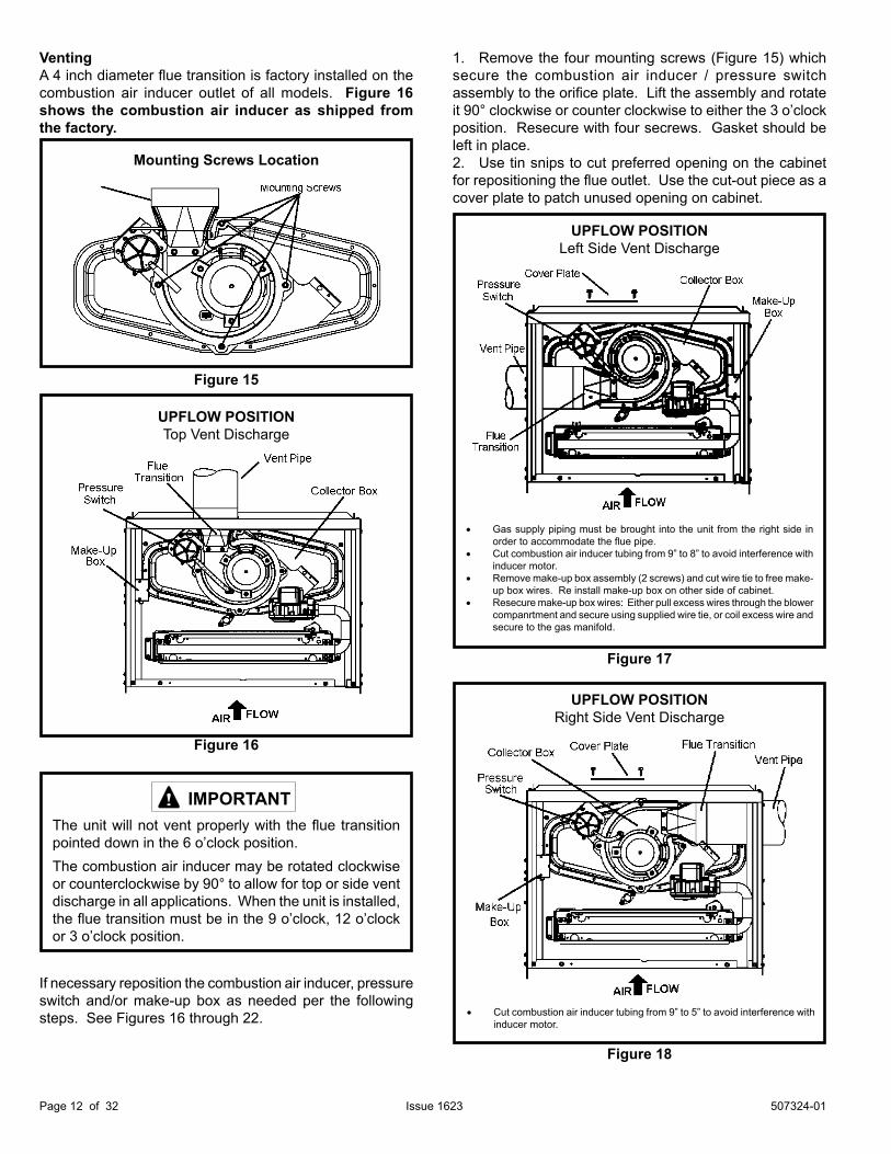
VentingA 4 inch diameter flue transition is factory installed on the combustion air inducer outlet of all models. Figure 16 shows the combustion air inducer as shipped from the factory.
The unit will not vent properly with the flue transition pointed down in the 6 o’clock position.
IMPORTANT
1. Remove the four mounting screws (Figure 15) which secure the combustion air inducer / pressure switch assembly to the orifice plate. Lift the assembly and rotate it 90° clockwise or counter clockwise to either the 3 o’clock position. Resecure with four secrews. Gasket should be left in place.2. Use tin snips to cut preferred opening on the cabinet for repositioning the flue outlet. Use the cut-out piece as a cover plate to patch unused opening on cabinet.
Figure 18
UPFLOW POSITIONRight Side Vent Discharge
• Cut combustion air inducer tubing from 9” to 5” to avoid interference with inducer motor.
Mounting Screws Location
Figure 15
Figure 16
UPFLOW POSITIONTop Vent Discharge
The combustion air inducer may be rotated clockwise or counterclockwise by 90° to allow for top or side vent discharge in all applications. When the unit is installed, the flue transition must be in the 9 o’clock, 12 o’clock or 3 o’clock position.
If necessary reposition the combustion air inducer, pressure switch and/or make-up box as needed per the following steps. See Figures 16 through 22.
Figure 17
• Gas supply piping must be brought into the unit from the right side in order to accommodate the flue pipe.
• Cut combustion air inducer tubing from 9” to 8” to avoid interference with inducer motor.
• Remove make-up box assembly (2 screws) and cut wire tie to free make-up box wires. Re install make-up box on other side of cabinet.
• Resecure make-up box wires: Either pull excess wires through the blower companrtment and secure using supplied wire tie, or coil excess wire and secure to the gas manifold.
UPFLOW POSITIONLeft Side Vent Discharge
507324-01 Page 13 of 32Issue 1623
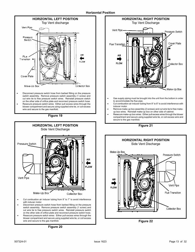
Horizontal Position
HORIZONTAL RIGHT POSITIONSide Vent Discharge
Figure 22
HORIZONTAL LEFT POSITIONSide Vent Discharge
Figure 20
• Cut combustion air inducer tubing from 9” to 7” to avoid interference with inducer motor.
• Disconnect pressure switch hose from barbed fitting on the pressure switch assembly. Remove pressure switch assembly (1 screw) and cut wire tie to free pressure switch wires. Reinstall pressure switch on the other side of orifice plate and reconnect pressure switch hose.
• Resecure pressure seitch wires: Either pull excess wires through the blower compartment and secure using supplied wire tie, or coil excess wire and secure to the gas manifold.
HORIZONTAL RIGHT POSITIONTop Vent Discharge
Figure 21
• Gas supply piping must be brought into the unit from the bottom in order to accommodate the flue pipe.
• Cut combustion air inducer tubing from 9” to 8” to avoid interference with inducer motor.
• Remove make-up box assembly (2 screws) and cut wire tie to free make-up box wires. Reinstall make-up box on other side of cabinet.
• Resecure make-up box wires: Either pull excess wires through the blower compartment and secure using supplied wire tie, or coil excess wire and secure to the gas manifold.
HORIZONTAL LEFT POSITIONTop Vent discharge
Figure 19
• Disconnect pressure switch hose from barbed fitting on the pressure switch assembly. Remove pressure switch assembly (1 screw) and cut wire tie to free pressure switch wires. Reinstall pressure switch on the other side of orifice plate and reconnect pressure switch hose.
• Resecure pressure seitch wires: Either pull excess wires through the blower compartment and secure using supplied wire tie, or coil excess wire and secure to the gas manifold.
507324-01Page 14 of 32 Issue 1623
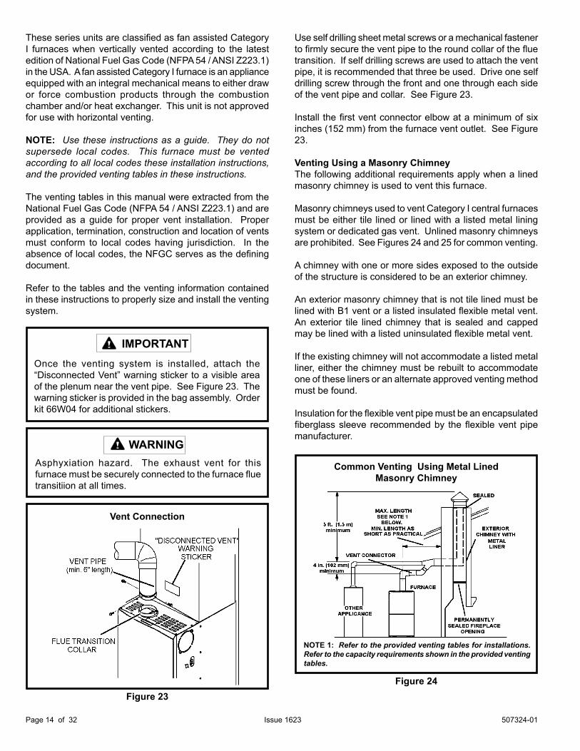
Once the venting system is installed, attach the “Disconnected Vent” warning sticker to a visible area of the plenum near the vent pipe. See Figure 23. The warning sticker is provided in the bag assembly. Order kit 66W04 for additional stickers.
IMPORTANT
These series units are classified as fan assisted Category I furnaces when vertically vented according to the latest edition of National Fuel Gas Code (NFPA 54 / ANSI Z223.1) in the USA. A fan assisted Category I furnace is an appliance equipped with an integral mechanical means to either draw or force combustion products through the combustion chamber and/or heat exchanger. This unit is not approved for use with horizontal venting.
NOTE: Use these instructions as a guide. They do not supersede local codes. This furnace must be vented according to all local codes these installation instructions, and the provided venting tables in these instructions.
The venting tables in this manual were extracted from the National Fuel Gas Code (NFPA 54 / ANSI Z223.1) and are provided as a guide for proper vent installation. Proper application, termination, construction and location of vents must conform to local codes having jurisdiction. In the absence of local codes, the NFGC serves as the defining document.
Refer to the tables and the venting information contained in these instructions to properly size and install the venting system.
Asphyxiation hazard. The exhaust vent for this furnace must be securely connected to the furnace flue transitiion at all times.
WARNING
Use self drilling sheet metal screws or a mechanical fastener to firmly secure the vent pipe to the round collar of the flue transition. If self drilling screws are used to attach the vent pipe, it is recommended that three be used. Drive one self drilling screw through the front and one through each side of the vent pipe and collar. See Figure 23.
Install the first vent connector elbow at a minimum of six inches (152 mm) from the furnace vent outlet. See Figure 23.
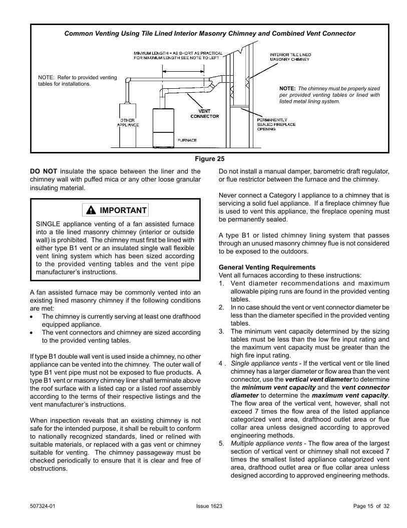
Venting Using a Masonry ChimneyThe following additional requirements apply when a lined masonry chimney is used to vent this furnace. Masonry chimneys used to vent Category I central furnaces must be either tile lined or lined with a listed metal lining system or dedicated gas vent. Unlined masonry chimneys are prohibited. See Figures 24 and 25 for common venting.
A chimney with one or more sides exposed to the outside of the structure is considered to be an exterior chimney.
An exterior masonry chimney that is not tile lined must be lined with B1 vent or a listed insulated flexible metal vent. An exterior tile lined chimney that is sealed and capped may be lined with a listed uninsulated flexible metal vent.
If the existing chimney will not accommodate a listed metal liner, either the chimney must be rebuilt to accommodate one of these liners or an alternate approved venting method must be found.
Insulation for the flexible vent pipe must be an encapsulated fiberglass sleeve recommended by the flexible vent pipe manufacturer.
Figure 24
Common Venting Using Metal LinedMasonry Chimney
NOTE 1: Refer to the provided venting tables for installations. Refer to the capacity requirements shown in the provided venting tables.
Figure 23
Vent Connection
507324-01 Page 15 of 32Issue 1623
DO NOT insulate the space between the liner and the chimney wall with puffed mica or any other loose granular insulating material.
SINGLE appliance venting of a fan assisted furnace into a tile lined masonry chimney (interior or outside wall) is prohibited. The chimney must first be lined with either type B1 vent or an insulated single wall flexible vent lining system which has been sized according to the provided venting tables and the vent pipe manufacturer’s instructions.
IMPORTANT
A fan assisted furnace may be commonly vented into an existing lined masonry chimney if the following conditions are met:• The chimney is currently serving at least one drafthood equipped appliance.• The vent connectors and chimney are sized according
to the provided venting tables.
If type B1 double wall vent is used inside a chimney, no other appliance can be vented into the chimney. The outer wall of type B1 vent pipe must not be exposed to flue products. A type B1 vent or masonry chimney liner shall terminate above the roof surface with a listed cap or a listed roof assembly according to the terms of their respective listings and the vent manufacturer’s instructions.
When inspection reveals that an existing chimney is not safe for the intended purpose, it shall be rebuilt to conform to nationally recognized standards, lined or relined with suitable materials, or replaced with a gas vent or chimney suitable for venting. The chimney passageway must be checked periodically to ensure that it is clear and free of obstructions.
Do not install a manual damper, barometric draft regulator, or flue restrictor between the furnace and the chimney.
Never connect a Category I appliance to a chimney that is servicing a solid fuel appliance. If a fireplace chimney flue is used to vent this appliance, the fireplace opening must be permanently sealed.
A type B1 or listed chimney lining system that passes through an unused masonry chimney flue is not considered to be exposed to the outdoors.
General Venting RequirementsVent all furnaces according to these instructions:1. Vent diameter recommendations and maximum
allowable piping runs are found in the provided venting tables.
2. In no case should the vent or vent connector diameter be less than the diameter specified in the provided venting tables.
3. The minimum vent capacity determined by the sizing tables must be less than the low fire input rating and the maximum vent capacity must be greater than the high fire input rating.
4 . Single appliance vents - If the vertical vent or tile lined chimney has a larger diameter or flow area than the vent connector, use the vertical vent diameter to determine the minimum vent capacity and the vent connector diameter to determine the maximum vent capacity. The flow area of the vertical vent, however, shall not exceed 7 times the flow area of the listed appliance categorized vent area, drafthood outlet area or flue collar area unless designed according to approved engineering methods.
5. Multiple appliance vents - The flow area of the largest section of vertical vent or chimney shall not exceed 7 times the smallest listed appliance categorized vent area, drafthood outlet area or flue collar area unless designed according to approved engineering methods.
Common Venting Using Tile Lined Interior Masonry Chimney and Combined Vent Connector
NOTE: Refer to provided ventingtables for installations.
NOTE: The chimney must be properly sized per provided venting tables or lined with listed metal lining system.
Figure 25
507324-01Page 16 of 32 Issue 1623
6. The entire length of single wall metal vent connector shall be readily accessible for inspection, cleaning, and replacement.
7. Single appliance venting configurations with zero lateral lengths (Table 3) are assumed to have no elbows in the vent system. For all other vent configurations, the vent system is assumed to have two 90° elbows. For each additional 90° elbow or equivalent (for example two 45° elbows equal one 90° elbow) beyond two, the maximum capacity listed in the venting table should be reduced by 10% (0.90 x maximum listed capacity).
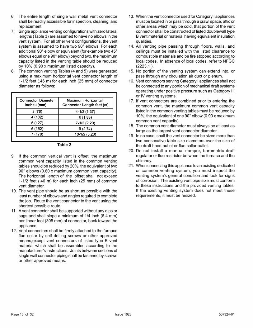
8. The common venting Tables (4 and 5) were generated using a maximum horizontal vent connector length of 1-1/2 feet (.46 m) for each inch (25 mm) of connector diameter as follows:
9. If the common vertical vent is offset, the maximum common vent capacity listed in the common venting tables should be reduced by 20%, the equivalent of two 90° elbows (0.80 x maximum common vent capacity). The horizontal length of the offset shall not exceed 1-1/2 feet (.46 m) for each inch (25 mm) of common vent diameter.
10. The vent pipe should be as short as possible with the least number of elbows and angles required to complete the job. Route the vent connector to the vent using the shortest possible route.
11. A vent connector shall be supported without any dips or sags and shall slope a minimum of 1/4 inch (6.4 mm) per linear foot (305 mm) of connector, back toward the appliance.
12. Vent connectors shall be firmly attached to the furnace flue collar by self drilling screws or other approved
means,except vent connectors of listed type B vent material which shall be assembled according to the manufacturer’s instructions. Joints between sections of single wall connector piping shall be fastened by screws or other approved means.
13. When the vent connector used for Category I appliances must be located in or pass through a crawl space, attic or other areas which may be cold, that portion of the vent connector shall be constructed of listed doublewall type B vent material or material having equivalent insulation qualities.
14. All venting pipe passing through floors, walls, and ceilings must be installed with the listed clearance to combustible materials and be fire stopped according to local codes. In absence of local codes, refer to NFGC (2223.1 ).
15. No portion of the venting system can extend into, or pass through any circulation air duct or plenum.
16. Vent connectors serving Category I appliances shall not be connected to any portion of mechanical draft systems operating under positive pressure such as Category III or IV venting systems.
17. If vent connectors are combined prior to entering the common vent, the maximum common vent capacity listed in the common venting tables must be reduced by 10%, the equivalent of one 90° elbow (0.90 x maximum common vent capacity).
18. The common vent diameter must always be at least as large as the largest vent connector diameter.19. In no case, shall the vent connector be sized more than two consecutive table size diameters over the size of
the draft hood outlet or flue collar outlet.20. Do not install a manual damper, barometric draft
regulator or flue restrictor between the furnace and the chimney.21. When connecting this appliance to an existing dedicated
or common venting system, you must inspect the venting system’s general condition and look for signs of corrosion. The existing vent pipe size must conform to these instructions and the provided venting tables. If the existing venting system does not meet these requirements, it must be resized.
Table 2
507324-01 Page 17 of 32Issue 1623
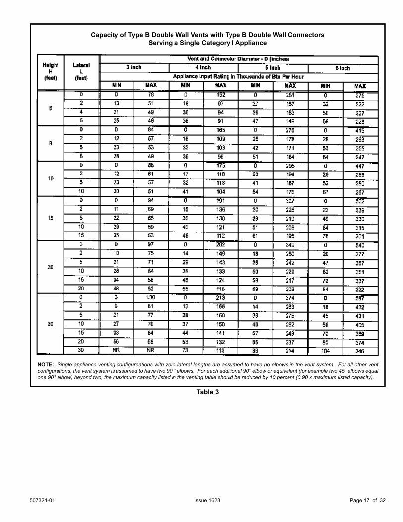
Capacity of Type B Double Wall Vents with Type B Double Wall ConnectorsServing a Single Category I Appliance
Table 3
NOTE: Single appliance venting configureations with zero lateral lengths are assumed to have no elbows in the vent system. For all other vent configurations, the vent system is assumed to have two 90 ° elbows. For each additional 90° elbow or equivalent (for example two 45° elbows equal one 90° elbow) beyond two, the maximum capacity listed in the venting table should be reduced by 10 percent (0.90 x maximum listed capacity).
507324-01Page 18 of 32 Issue 1623
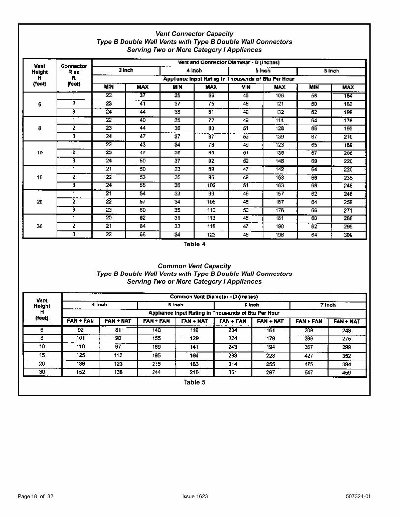
Vent Connector CapacityType B Double Wall Vents with Type B Double Wall Connectors
Serving Two or More Category I Appliances
Common Vent CapacityType B Double Wall Vents with Type B Double Wall Connectors
Serving Two or More Category I Appliances
Table 4
Table 5
507324-01 Page 19 of 32Issue 1623
Removal of the Furnace from Common VentIn the event that an existing furnace is removed from a venting system commonly run with separate gas appliances, the venting system is likely to be too large to properly vent the remaining attached appliances.
Conduct the following test while each appliance is operating and the other appliances (which are not operating) remain connected to the common venting system. If the venting system has been installed improperly, you must correct the system as indicated in the general venting requirements section.
The following steps shall be followed for each appliance connected to the venting system being placed into operation, while all other appliances connected to the venting system are not in operation:
1. Seal any unused openings in the common venting system.
2. Inspect the venting system for proper size and horizontal pitch. Determine that there is no blockage, restriction, leakage, corrosion, or other deficiencies which could cause an unsafe condition.
3. Close all building doors and windows and all doors between the space in which the appliances remaining connected to the common venting system are located and other spaces of the building. Turn on clothes dryers and any appliances not connected to the common venting system. Turn on any exhaust fans, such as range hoods and bathroom exhausts, so they will operate at maximum speed. Do not operate a summer exhaust fan. Close fireplace dampers.
4. Follow the lighting instructions. Turn on the appliance that is being inspected. Adjust the thermostat so that the appliance operates continuously.
5. After the burners have operated for 5 minutes, test for leaks of flue gases at the draft hood relief opening. Use the flame of a match or candle.
6. After determining that each appliance connected to the common venting system is venting properly, (step 3) return all doors, windows, exhaust fans, fireplace dampers, and any other gas burning appliances to their previous mode of operation.
7. If a venting problem is found during any of the preceding tests, the common venting system must be modified to correct the problem.
Resize the common venting system to the minimum vent pipe size determined by using the appropriate tables in Appendix G. (These are in the current standards of the National Fuel Gas Code ANSI 2223.1.
CARBON MONOXIDE POISONING HAZARDFailure to follow the steps outlined below for each appliance connected to the venting system being placed into operation could result in carbon monoxide poisoning or death.
WARNINGGas Supply1. This unit is shipped standard for left or right side
installation of gas piping (or top entry in horizontal applications). Connect the gas supply to the piping assembly.
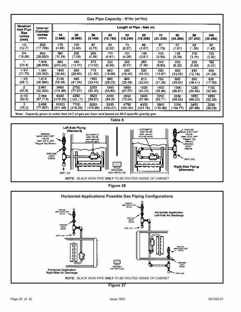
2. When connecting the gas supply piping, consider factors such as length of run, number of fittings, and furnace rating to avoid excessive pressure drop. Table 6 lists recommended pipe sizes for typical applications.
3. The gas piping must not run in or through air ducts, clothes chutes, gas vents or chimneys, dumb waiters, or elevator shafts.
4. The piping should be sloped 1/4 inch (6.4 mm) per 15 feet (4.57 m) upward toward the meter from the furnace. The piping must be supported at proper intervals [every 8 to 10 feet (2.44 to 3.01 m)] with suitable hangers or straps. Install a drip leg in vertical pipe runs to the unit.
5. A 1/8” N.P.T. plugged tap or pressure post is located on the gas valve to facilitate test gauge connection. See Figure 35.
6. In some localities, codes may require the installation of a manual main shut off valve and union (furnished by the installer) external to the unit. The union must be of the ground joint type.
Gas Piping
If a flexible gas connector is required or allowed by the authority that has jurisdiction, black iron pipe shall be installed at the gas valve and extend outside the furnace cabinet. The flexible connector can then be added between the black iron pipe and the gas supply line.
CAUTION
NOTE: If emergency shutoff is necessary, shut off the main manual gas valve and disconnect main power to the furnace. The installer should properly label these devices.
Compounds used on threaded joints of gas piping must be resistant to the actions of liquified petroleum gases.
IMPORTANT
507324-01Page 20 of 32 Issue 1623
Horizontal Applications Possible Gas Piping Configurations
NOTE: BLACK IRON PIPE ONLY TO BE ROUTED INSIDE OF CABINET
Figure 27
NOTE: BLACK IRON PIPE ONLY TO BE ROUTED INSIDE OF CABINET
Figure 26
Table 6
Gas Pipe Capacity - ft³/hr (m³/hr)
Note: Capacity given in cubic feet (m³) of gas per hour and based on 06.0 specific gravity gas.
507324-01 Page 21 of 32Issue 1623
Leak CheckAfter gas piping is completed, carefully check all piping connections (factory and field installed) for gas leaks. Use a leak detecting solution or other preferred means.
NOTE: If emergency shutoff is necessary, shut off the main manual gas valve and disconnect the main power to the furnace. The installer should properly label these devices.
Some soaps used for leak detection are corrosive to certain metals. Carefully rinse piping thoroughly after leak test has been completed. Do not use matches, candles, flame or other sources of ignition to check for gas leaks.
CAUTION
The furnace must be isolated by closing its individual manual shut-off valve and disconnecting from from the gas supply system the during any pressure testing of the gas supply system at pressures less than or equal to 1/2 psig (3.48 kPa, 14 inches w.c.).
Electrical
ELECTROSTATIC DISCHARGE (ESD)Precautions and Procedures
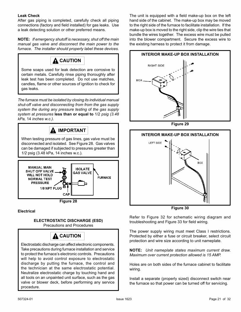
When testing pressure of gas lines, gas valve must be disconnected and isolated. See Figure 28. Gas valves can be damaged if subjected to pressures greater than 1/2 psig (3.48 kPa, 14 inches w.c.).
IMPORTANT
Electrostatic discharge can affect electronic components. Take precautions during furnace installation and service to protect the furnace’s electronic controls. Precautions will help to avoid control exposure to electrostatic discharge by putting the furnace, the control and the technician at the same electrostatic potential. Neutralize electrostatic charge by touching hand and all tools on an unpainted unit surface, such as the gas valve or blower deck, before performing any service procedure.
CAUTION
The unit is equipped with a field make-up box on the left hand side of the cabinet. The make-up box may be moved to the right side of the furnace to facilitate installation. If the make-up box is moved to the right side, clip the wire ties that bundle the wires together. The excess wire must be pulled into the blower compartment. Secure the excess wire to the existing harness to protect it from damage.
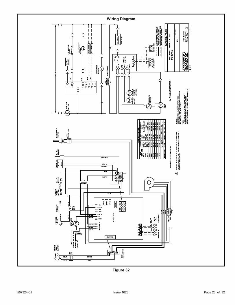
Refer to Figure 32 for schematic wiring diagram and troubleshooting and Figure 33 for field wiring.
The power supply wiring must meet Class I restrictions. Protected by either a fuse or circuit breaker, select circuit protection and wire size according to unit nameplate.
NOTE: Unit nameplate states maximum current draw. Maximum over current protection allowed is 15 AMP.
Holes are on both sides of the furnace cabinet to facilitate wiring.
Install a separate (properly sized) disconnect switch near the furnace so that power can be turned off for servicing.
INTERIOR MAKE-UP BOX INSTALLATION
Figure 29
Figure 28
INTERIOR MAKE-UP BOX INSTALLATION
Figure 30
507324-01Page 22 of 32 Issue 1623
Before connecting the thermostat, check to make sure the wires will be long enough for servicing at a later date. Make sure that thermostat wire is long enough to facilitate future removal of blower for service.
Complete the wiring connections to the equipment. Use the provided unit wiring diagram and the field wiring diagram shown in Figure 33. Use 18 gauge wire or larger that is suitable for Class II rating for thermostat connections.
Electrically ground the unit according to local codes or, in the absence of local codes, according to the current National Electric Code (ANSI/NFPA No. 70). A green ground wire is provided in the field make-up box.
NOTE: This furnace contains electronic components that are polarity sensitive. Make sure that the furnace is wired correctly and is properly grounded.
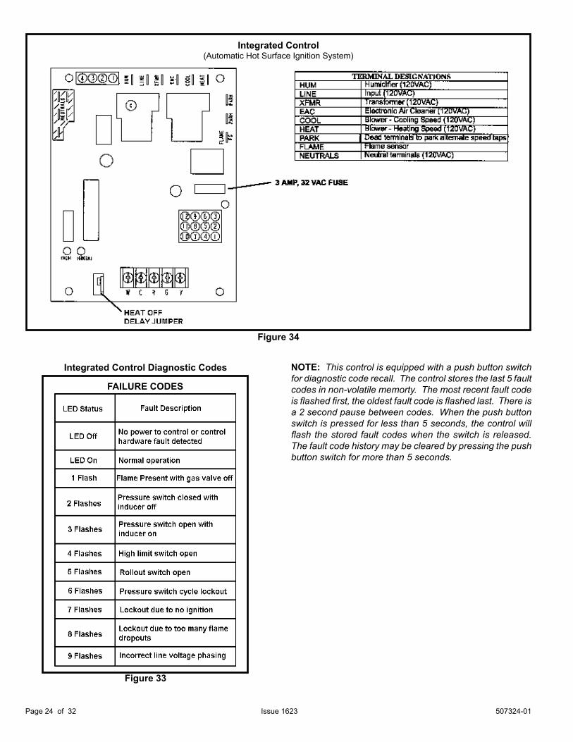
Accessory TerminalsOne line voltage “EAC” 1/4” spade terminal is provided on the furnace integrated control. See figure 34 for integrated control configuration. This terminal is energized when the indoor blower is operating. Any accessory rated up to one amp can be connected to this terminal with the neutral leg of the circuit being connected to one of the provided neutral terminals. If an accessory rated at greater than one amp is connected to this terminal, it is necessary to use an external relay.
One line voltage “HUM” 1/4” spade terminal is provided on the furnace integrated control. See Figure 34 for integrated control configuration. This terminal is energized in the heating mode when the combustion air inducer is operating. Any humidifier rated up to one amp can be connected to this terminal with the neutral leg of the circuit being connected to one of the provided neutral terminals. If a humidifier rated at greater than one amp is connected to this terminal, it is necessary to use an external relay relay.
Generator Use - Voltage RequirementsThe following requirements must be kept in mind when specifying a generator for use with this equipment:• The furnace requires 120 volts ± 10% (Range: 108 volts
to 132 volts).• The furnace operates at 60 Hz ± 5% (Range: 57 Hz to 63 Hz).• The furnace integrated control requires both polarity
and proper ground. Both polarity and proper grounding should be checked before attempting to operate the furnace on either permanent or temporary power.
• Generator should have a wave form distortion of less than 5% RHO.
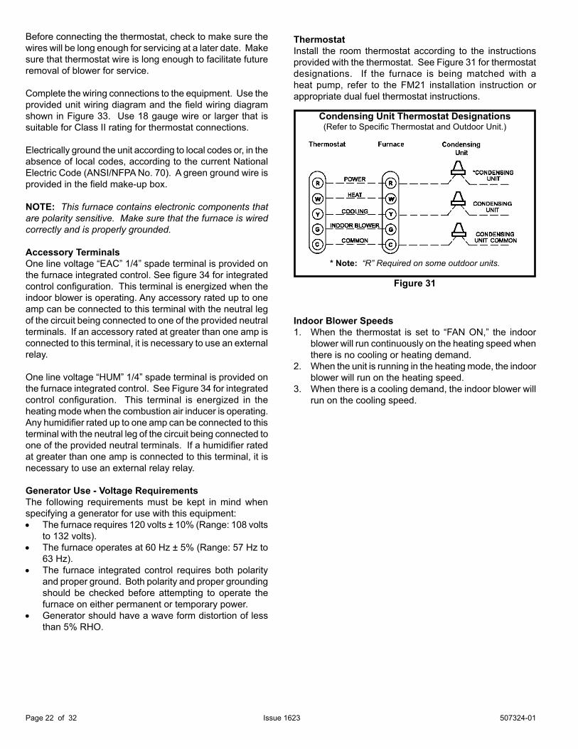
ThermostatInstall the room thermostat according to the instructions provided with the thermostat. See Figure 31 for thermostat designations. If the furnace is being matched with a heat pump, refer to the FM21 installation instruction or appropriate dual fuel thermostat instructions.
Indoor Blower Speeds1. When the thermostat is set to “FAN ON,” the indoor
blower will run continuously on the heating speed when there is no cooling or heating demand.
2. When the unit is running in the heating mode, the indoor blower will run on the heating speed.
3. When there is a cooling demand, the indoor blower will run on the cooling speed.
Condensing Unit Thermostat Designations(Refer to Specific Thermostat and Outdoor Unit.)
* Note: “R” Required on some outdoor units.
Figure 31
507324-01 Page 23 of 32Issue 1623
Wiring Diagram
Figure 32
507324-01Page 24 of 32 Issue 1623
FAILURE CODES
Figure 34
Integrated Control(Automatic Hot Surface Ignition System)
Integrated Control Diagnostic Codes NOTE: This control is equipped with a push button switch for diagnostic code recall. The control stores the last 5 fault codes in non-volatile memorty. The most recent fault code is flashed first, the oldest fault code is flashed last. There is a 2 second pause between codes. When the push button switch is pressed for less than 5 seconds, the control will flash the stored fault codes when the switch is released. The fault code history may be cleared by pressing the push button switch for more than 5 seconds.
Figure 33
507324-01 Page 25 of 32Issue 1623
BEFORE LIGHTING smell all around the appliance area for gas. Be sure to smell next to the floor because some gas is heavier than air and will settle on the floor.
The gas valve on this unit will be equipped with a gas control switch. Use only your hand to move the switch. Never use tools. If the switch will not turn or if the control switch will not move by hand, do not try to repair it.
Placing the Furnace into Operation:These units are equipped with an automatic ignition system. Do not attempt to manually light burners on these furnaces. Each time the thermostat calls for heat, the burners will automatically light. The ignitor does not get hot when there is no call for heat on units with an automatic ignition system.
Unit Start-Up
FOR YOUR SAFETY READ BEFORE LIGHTING UNIT.
Gas Valve Operation (Figure 35)1. STOP! Read the safety information at the beginning of
this section.2. Set the thermostat to the lowest setting.3. Turn off all electrical power to the unit.4. This furnace is equipped with an ignition device which
automatically lights the burners. Do not try to light the burners by hand.
5. Remove the upper access panel.
Do not use this furnace if any part have been underwater. Immediately call a licensed professional service technician (or equivalent) to inspect the furnace and to replace any part of the control system and any gas control which has been underwater.
WARNING
If overheating occurs or if gas supply fails to shut off, shut off the manual gas valve to the appliance before shutting off electrical supply.
WARNING
Before attempting to perform any service or maintenance, turn the electrical power to unit OFF at disconnect switch.
CAUTION
If you do not follow these instructions exactly, a fire or explosion may result causing property damage, personal injury or death.
WARNING
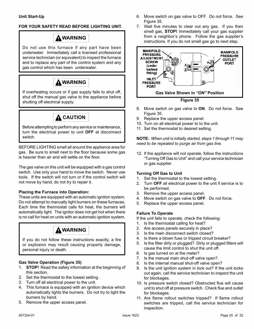
6. Move switch on gas valve to OFF. Do not force. See Figure 35.
7. Wait five minutes to clear out any gas. If you then smell gas, STOP! Immediately call your gas supplier from a neighbor’s phone. Follow the gas supplier’s instructions. If you do not smell gas go to next step.
8. Move switch on gas valve to ON. Do not force. See Figure 35.
9. Replace the upper access panel. 10. Turn on all electrical power to to the unit.11. Set the thermostat to desired setting.
NOTE: When unit is initially started, steps 1 through 11 may need to be repeated to purge air from gas line.
12. If the appliance will not operate, follow the instructions “Turning Off Gas to Unit” and call your service technician
or gas supplier.
Turning Off Gas to Unit1. Set the thermostat to the lowest setting.2. Turn OFF all electrical power to the unit if service is to
be performed.3. Remove the upper access panel.4. Move switch on gas valve to OFF. Do not force.5. Replace the upper access panel.
Failure To OperateIf the unit fails to operate, check the following:1. Is the thermostat calling for heat?2. Are access panels securely in place?3. Is the main disconnect switch closed?4. Is there a blown fuse or tripped circuit breaker?5. Is the filter dirty or plugged? Dirty or plugged filters will
cause the limit control to shut the unit off.6. Is gas turned on at the meter?7. Is the manual main shut-off valve open?8. Is the internal manual shut-off valve open?9. Is the unit ignition system in lock out? If the unit locks
out again, call the service technician to inspect the unit for blockages.
10. Is pressure switch closed? Obstructed flue will cause unit to shut off at pressure switch. Check flue and outlet for blockages.
11. Are flame rollout switches tripped? If flame rollout switches are tripped, call the service technician for inspection.
Figure 35Gas Valve Shown in “ON” Position
507324-01Page 26 of 32 Issue 1623
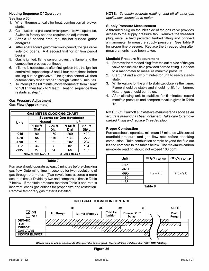
Heating Sequence Of Operation See figure 36.1. When thermostat calls for heat, combustion air blower starts.2. Combustion air pressure switch proves blower operation.
Switch is factory set and requires no adjustment.3. After a 15 second prepurge, the hot surface ignitor
energizes.4. After a 20 second ignitor warm-up period, the gas valve
solenoid opens. A 4 second trial for ignition period begins.
5. Gas is ignited, flame sensor proves the flame, and the combustion process continues.6. If flame is not detected after first ignition trial, the ignition
control will repeat steps 3 and 4 four more times before locking out the gas valve. The ignition control will then automatically repeat steps 1 through 6 after 60 minutes.
7. To interrupt the 60 minute, move thermostat from “Heat” to “OFF” then back to “Heat”. Heating sequence then restarts at step 1.
Gas Pressure Adjustment Gas Flow (Approximate)
Furnace should operate at least 5 minutes before checking gas flow. Determine time in seconds for two revolutions of gas through the meter. (Two revolutions assures a more accurate time.) Divide by two and compare to time in Table 7 below. If manifold pressure matches Table 9 and rate is incorrect, check gas orifices for proper size and restriction. Remove temporary gas meter if installed.
NOTE: To obtain accurate reading, shut off all other gas appliances connected to meter.
Supply Pressure MeasurementA threaded plug on the inlet side of the gas valve provides access to the supply pressure tap. Remove the threaded plug, install a field provided barbed fitting and connect a manometer to measure supply pressure. See Table 9 for proper line pressure. Replace the threaded plug after measurements have been taken.
Manifold Pressure Measurement1. Remove the threaded plug from the outlet side of the gas
valve and install a field provided barbed fitting. Connect to a manometer to measure manifold pressure.
2. Start unit and allow 5 minutes for unit to reach steady state.
3. While waiting for the unit to stabilize, observe the flame. Flame should be stable and should not lift from burner. Natural gas should burn blue.
4. After allowing unit to stabilize for 5 minutes, record manifold pressure and compare to value given in Table
12.
NOTE: Shut unit off and remove manometer as soon as an accurate reading has been obtained. Take care to remove barbed fitting and replace threaded plug.
Proper CombustionFurnace should operate a minimum 15 minutes with correct manifold pressure and gas flow rate before checking combustion. Take combustion sample beyond the flue out let and compare to the tables below. The maximum carbon monoxide reading should not exceed 100 ppm.
Table 8
INTEGRATED IGNITION CONTROL
Blower on time will be 45 seconds after gas valve is energized. Blower off time will depend on “OFF TIME” Setting.
Figure 36
Table 7
507324-01 Page 27 of 32Issue 1623
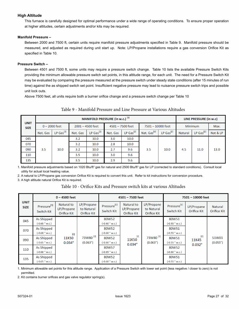
High Altitude This furnace is carefully designed for optimal performance under a wide range of operating conditions. To ensure proper operation
at higher altitudes, certain adjustments and/or kits may be required.
Manifold Pressure – Between 2000 and 7500 ft, certain units require manifold pressure adjustments specified in Table 9. Manifold pressure should be
measured, and adjusted as required during unit start up. Note: LP/Propane installations require a gas conversion Orifice Kit as specified in Table 10.
Pressure Switch – Between 4501 and 7500 ft, some units may require a pressure switch change. Table 10 lists the available Pressure Switch Kits
providing the minimum allowable pressure switch set points, in this altitude range, for each unit. The need for a Pressure Switch Kit may be evaluated by comparing the pressure measured at the pressure switch under steady state conditions (after 15 minutes of run time) against the as shipped switch set point. Insufficient negative pressure may lead to nuisance pressure switch trips and possible unit lock outs.
Above 7500 feet, all units require both a burner orifice change and a pressure switch change per Table 10
1. Manifold pressure adjustments based on 1020 Btu/ft3 gas for natural and 2500 Btu/ft3 gas for LP (corrected to standard conditions). Consult local utility for actual local heating value.
2. A natural to LP/Propane gas conversion Orifice Kit is required to convert this unit. Refer to kit instructions for conversion procedure.3. A high altitude natural Orifice Kit is required.
1. Minimum allowable set points for this altitude range. Application of a Pressure Switch with lower set point (less negative / closer to zero) is not permitted.
2. Kit contains burner orifices and gas valve regulator spring(s).
Table 9 - Manifold Pressure and Line Pressure at Various Altitudes
Table 10 - Orifice Kits and Pressure switch kits at various Altitudes
507324-01Page 28 of 32 Issue 1623
Blower Speeds Follow the steps below to change the blower speeds.1. Turn off electrical power to furnace.2. Remove blower access panel.3. Disconnect existing speed tap at integrated control
speed terminal.
NOTE: Termination of any unused motor leads must be insulated.
4. Place unused blower speed tap on integrated control “PARK” terminal or insulate.5. Refer to blower speed selection chart on unit wiring
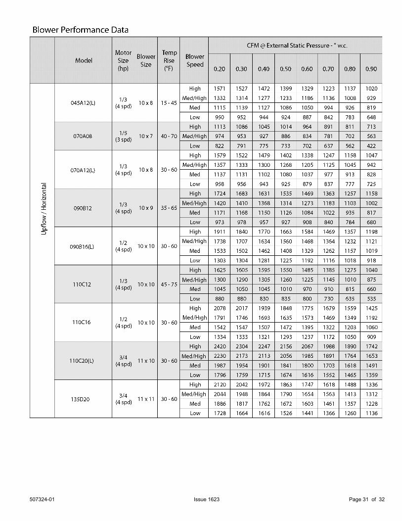
diagram for desired heating or cooling speed. See Blower performance data beginning on the next page.
6. Connect selected speed tap at integrated control speed terminal.
7. Resecure blower access panel.8. Turn on electrical power to furnace.9. Recheck temperature rise.
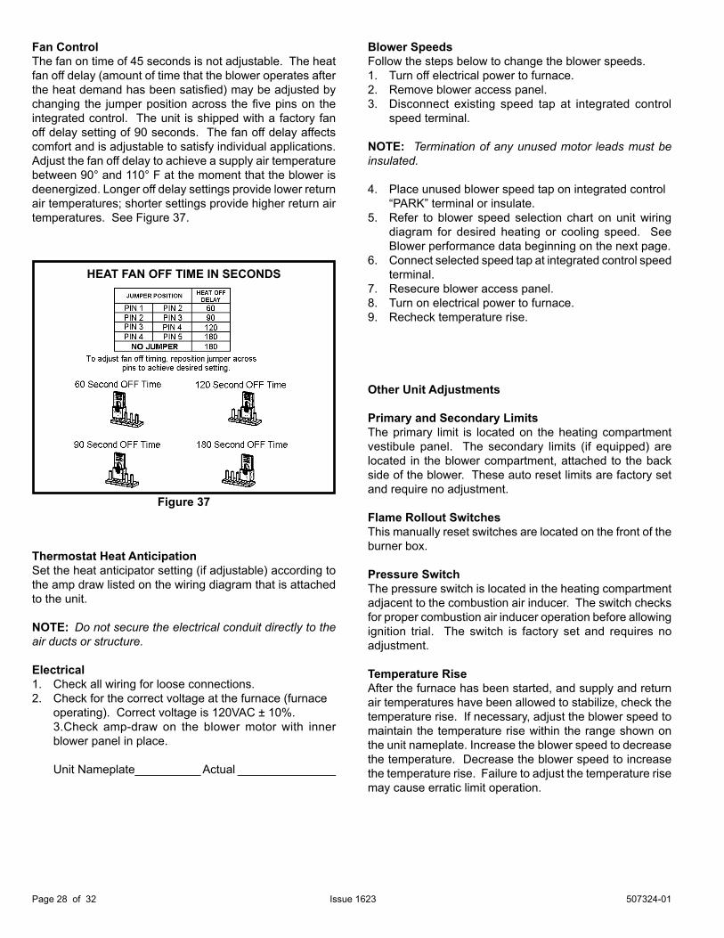
Fan ControlThe fan on time of 45 seconds is not adjustable. The heat fan off delay (amount of time that the blower operates after the heat demand has been satisfied) may be adjusted by changing the jumper position across the five pins on the integrated control. The unit is shipped with a factory fan off delay setting of 90 seconds. The fan off delay affects comfort and is adjustable to satisfy individual applications. Adjust the fan off delay to achieve a supply air temperature between 90° and 110° F at the moment that the blower is deenergized. Longer off delay settings provide lower return air temperatures; shorter settings provide higher return air temperatures. See Figure 37.
Thermostat Heat AnticipationSet the heat anticipator setting (if adjustable) according to the amp draw listed on the wiring diagram that is attached to the unit.
NOTE: Do not secure the electrical conduit directly to the air ducts or structure.
Electrical1. Check all wiring for loose connections.2. Check for the correct voltage at the furnace (furnace operating). Correct voltage is 120VAC ± 10%. 3.Check amp-draw on the blower motor with inner
blower panel in place.
Unit Nameplate__________ Actual _______________
HEAT FAN OFF TIME IN SECONDS
Figure 37
Other Unit Adjustments
Primary and Secondary LimitsThe primary limit is located on the heating compartment vestibule panel. The secondary limits (if equipped) are located in the blower compartment, attached to the back side of the blower. These auto reset limits are factory set and require no adjustment.
Flame Rollout SwitchesThis manually reset switches are located on the front of the burner box.
Pressure SwitchThe pressure switch is located in the heating compartment adjacent to the combustion air inducer. The switch checks for proper combustion air inducer operation before allowing ignition trial. The switch is factory set and requires no adjustment.
Temperature RiseAfter the furnace has been started, and supply and return air temperatures have been allowed to stabilize, check the temperature rise. If necessary, adjust the blower speed to maintain the temperature rise within the range shown on the unit nameplate. Increase the blower speed to decrease the temperature. Decrease the blower speed to increase the temperature rise. Failure to adjust the temperature rise may cause erratic limit operation.
507324-01 Page 29 of 32Issue 1623
Cleaning the Burners
NOTE: Use papers or protective covering in front of the furnace during cleaning.
1. Turn off both electrical and gas power supplies to furnace.
2. Label the wires from gas valve, rollout switches, primary limit switch and make-up box then disconnect them.
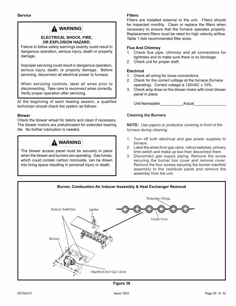
3. Disconnect gas supply piping. Remove the screw securing the burner box cover and remove cover. Remove the four screws securing the burner manifold assembly to the vestibule panel and remove the assembly from the unit.
Figure 38
Burner, Combustion Air Inducer Assembly & Heat Exchanger Removal
Service
ELECTRICAL SHOCK, FIRE,OR EXPLOSION HAZARD.
Failure to follow safety warnings exactly could result in dangerous operation, serious injury, death or property damage.
Improper servicing could result in dangerous operation, serious injury, death, or property damage. Before servicing, disconnect all electrical power to furnace.
When servicing controls, label all wires prior to disconnecting. Take care to reconnect wires correctly. Verify proper operation after servicing.
WARNING
At the beginning of each heating season, a qualified technician should check the system as follows:
BlowerCheck the blower wheel for debris and clean if necessary. The blower motors are prelubricated for extended bearing life. No further lubrication is needed.
FiltersFilters are installed external to the unit. Filters should be inspected monthly. Clean or replace the filters when necessary to ensure that the furnace operates properly. Replacement filters must be rated for high velocity airflow. Table 1 lists recommended filter sizes.
Flue And Chimney1. Check flue pipe, chimney and all connections for
tightness and to make sure there is no blockage.2. Check unit for proper draft.
Electrical1. Check all wiring for loose connections.2. Check for the correct voltage at the furnace (furnace operating). Correct voltage is 120VAC ± 10%.3. Check amp draw on the blower motor with inner blower
panel in place.
Unit Nameplate___________Actual_______________
The blower access panel must be securely in place when the blower and burners are operating. Gas fumes, which could contain carbon monoxide, can be drawn into living space resulting in personal injury or death.
WARNING
507324-01Page 30 of 32 Issue 1623
Cabinet Parts Upper access panel Blower panel Top cap
Control Panel Parts Transformer Integrated control Door interlock switch Circuit breaker
Blower Parts Blower wheel Blower housing Motor Motor mounting frame Motor capacitor Blower housing cutoff plate
Repair Parts ListThe following repair parts are available through independent Allied Air dealers. When ordering parts, include the complete furnace model number listed on the CSA International nameplate — Example: A801UH045JP24A-01. All service must be performed by a licensed professional installer (or equivalent), service agency, or gas supplier.
Heating Parts Flame sensor Heat exchanger assembly Gas manifold Combustion air inducer Gas valve Main burner cluster Main burner orifices Pressure switch Ignitor Primary limit control Flame rollout switch Secondary limit
4. To clean burners, run a vacuum cleaner with a soft brush attachment over the face of burners. Visually inspect inside the burners and crossovers for any blockage caused by foreign matter. Remove any blockage. Figure 34 shows burner detail.
5. Reinstall burner box, manifold assembly and burner box cover.
6. Re-install gas supply and turn on electrical pwer to furnace.
507324-01 Page 31 of 32Issue 1623
507324-01Page 32 of 32 Issue 1623
REQUIREMENTS for COMMONWEALTH of MASSACHUSETTS
Modifications to NFPA-54, Chapter 10 -Revise NFPA-54 section 10.8.3 to add the following requirements:For all side wall, horizontally vented, gas fueled equipment installed in every dwelling, building or structure used in whole or in part for residential purposes, including those owned or operated by the Commonwealth and where the side wall exhaust vent termination is less than seven (7) feet above the finished grade in the area of the venting, including but not limited to decks and porches, the following requirements shall be satisfied:1. INSTALLATION OF CARBON MONOXIDE
DETECTORS. At the time of installation of the side wall, horizontally vented, gas-fueled equipment, the installing plumber or gas fitter shall observe that a hard wired carbon monoxide detector with an alarm and battery backup is installed on the floor level where the gas equipment is to be installed. In addition, the installing plumber or gas fitter shall observe that a battery operated or hard wired carbon monoxide detector with an alarm is installed on each additional level of the dwelling, building or structure served by the side wall, horizontally vented, gas fueled equipment. It shall be the responsibility of the property owner to secure the services of qualified licensed professionals for the installation of hard wired carbon monoxide detectors.
a. In the event that the side wall, horizontally vented, g a s f u e l e d equipment is installed in a crawl space or an attic, the hard wired carbon monoxide detector with alarm and battery backup may be installed on the next adjacent floor level.
b. In the event that the requirements of this subdivision cannot be met at the time of completion of installation, the owner shall have a period of thirty (30) days to comply with the above requirements; provided, however, that during said thirty (30) day period, a battery operated carbon monoxide detector with an alarm shall be installed.
2. APPROVED CARBON MONOXIDE DETECTORS. Each carbon monoxide detector as required in accordance with the above provisions shall comply with NFPA 720 and be ANSI/UL 2034 listed and IAS certified.
3. SIGNAGE. A metal or plastic identification plate shall be permanently mounted to the exterior of the building at a minimum height of eight (8) feet above grade directly in line with the exhaust vent terminal for the horizontally vented, gas fueled heating appliance or equipment. The sign shall read, in print size no less than one half (1/2) inch in size, “GAS VENT DIRECTLY BELOW. KEEP CLEAR OF ALL OBSTRUCTIONS.”
4. INSPECTION. The state or local gas inspector of the side wall, horizontally vented, gas-fueled equipment shall not approve the installation unless, upon inspection, the inspector observes carbon monoxide detectors and signage installed in accordance with the provisions of 248 CMR 5.08(2)(a) 1 through 4.
EXEMPTIONS: The following equipment is exempt from 24 CMR 5.08(2)(a) 1 through 4:
1. The equipment listed in Chapter 10 entitled “Equipment Not Required to Be Vented” in the most current edition of NFPA 54 as adopted by the Board; and
2. Product Approved side wall, horizontally vented, gas fueled equipment installed in a room or structure separate from the dwelling, building or structure used in whole or in part for residential purposes.
MANUFACTURER REQUIREMENTS - GAS EQUIPMENT VENTING SYSTEM PROVIDED. When the manufacturer of Product Approved side wall, horizontally vented, gas fueled equipment provides a venting system design or venting system components with the equipment, the instructions provided by the manufacturer for installation of the equipment and the venting system shall include:1. Detailed instructions for the installation of the venting
system design or the venting system components: and 2. A complete parts list for the venting system design or
venting system.
MANUFACTURER REQUIREMENTS - GAS EQUIPMENT VENTING SYSTEM NOT PROVIDED. When the manufacturer of Product Approved sidewall, horizontally vented, gas fueled equipment does not provide the parts for venting the flue gases, but identifies “special venting systems,” the following requirements shall be satisfied by the manufacturer:1. The referenced “special venting system” instructions
shall be included with the appliance or equipment installation instructions; and
2. The “special venting systems” shall be Product Approved by the Board, and the instructions for that system shall include a parts list and detailed installation instructions.
A copy of all installation instructions for all Product Approved side wall, horizontally vented, gas fueled equipment, all venting instructions, all parts lists for venting instructions, and/or all venting design instructions shall remain with the appliance or equipment at the completion of the installation.