Embed Size (px)
Citation preview

FOR SPLIT DOUBLEWALL TANK SUMPS
S. Bravo Systems, Inc.
2929 Vail Ave. - Commerce, CA 90040
(323) 888-4133 - FAX: (323) 888-4123
www.SBravo.com
Split (2 joint) Tank Sump Models:B401-D-AB
B402-D-AB
B401-D-AB-XT
ii-B401-DW-SP-10A
INSTALLATION INSTRUCTIONS
There are no Tall Collars (Base/Collar)
for Split Sump Configurations.

READ THESE INSTRUCTIONS - KEEP FOR FUTURE REFERENCE
TABLE OF CONTENTS
DRY FITTING SUMP & EQUIPMENT................................ p. 4
A) Preparing the Tank Collar and Tank Sump Base............... p. 4-5
B) Joining the Tank Sump Base to the Tank Collar................p. 6-7
C) Fiberglassing Tank Sump Base to Tank Collar...................p. 8-9
D) Testing Base to Collar Fiberglass Install............................p. 10
Install & Test Penetration Fittings.......................................D.3-D.5E) Preparing the Tank Sump Base and Body......................... p. 12
F) Joining the Tank Sump Body to Base................................ p. 12-13
G) Testing the Body to Base Install......................................... p. 13-14
H) Fiberglassing the Body to Base......................................... p. 14-15
I) Mantadory Air Integrity Test................................................p. 16
J) Vacuum / Hydrostatic Filling...............................................p. 17-18
K) Advanced Leak Detection Procedure.................................p. 19-20
L) Attaching the Manometer....................................................p. 21
M) Concrete and Backfill Guidelines....................................... p. 22
WARRANTYAll containment systems sold by S. Bravo Systems, Inc. are warranted to be free from defects in material and workmanship for a period of one year from date of
purchase. This warranty will be limited to the repair and replacement of Bravo parts only and will exclude all claims for labor or consequential damage. No other
express warranties given and no affirmation of S. Bravo Systems, Inc., or its agents and/or representatives, by words or action, will constitute a warranty. IT IS
EXPRESSLY AGREED THAT THIS WARRANTY WILL BE IN LIEU OF ALL WARRANTIES OF FITNESS AND IN LIEU OF THE WARRANTY OF MERCHANTABILITY.
This warranty is void if there is any evidence of modification, abuse, negligence, or improper installation. If any fittings or components, other than S. Bravo Systems
approved fittings or components, are used in conjunction with any S. Bravo Systems product, the warranty pertaining to these products is immediately void.
2
The B-401 Doublewall Split Sump Series from S. Bravo Systems, Inc. MUST be
installed by, and only by, Bravo Certified Installers. Details can be found at
www.sbravo.com/cer t
Filling Bravo Systems Double Wall Products with
Brine (saline) solution will void the product warranty.
You must use only Bravo-Supplied Interstitial Fluid.
- Closely adhere to all directions and warnings indicated on the productor contained in these instructions. This includes following the OTHER manufacturers recommendations and Installation guidelines including -but not limited to- equipment
associated or in contact with, Bravo Systems Products.
- Warranty is void if there is any evidence of modification, abuse, negligence or improper installation.
SAFETY FIRST! S. Bravo Systems, Inc. urges you to carefully adhere to the normal safetyprocedures and precautions followed by your company. Please follow the mandates andcompliances decreed by OSHA, local, State and federal regulations regarding the use of this product.
ii-B401-DW-SP-10A
3
San
din
g B
lock
Paste M
ixer
Brush
4” Paint r
oller
Resin
Mix
ing s
tick
4” P
utty
knife
REQUIRED TOOLS(NOT PROVIDED)
Power/air Sanders. Acetone to clean up
tools/applicators. Power Cutting Tools.
An extra Barrel Roller. Extra Paint Roller.
Hand pump.
TOOL KIT (per site)
One 4” Paint Roller, One Metal Paste Mixer,
One Paint Stirring Stick, One 4” Putty Knife,
One Metal Chamfer Roller, One 5 quart
mixing bucket. One 250’ by 1” Roll of Masking
tape per 2 Sumps. MSDS for materials.
RESIN KIT PER SPLIT
SUMP (2 Joints) 5 Gal of Resin. 2 Qt. of Paste. Resin Catalyst.
Paste Catalyst. Mixing Buckets. 8 Pairs Nitrile
Gloves. Two 90’ Rolls of Fiberglass Mat. An
extra Two 30’ lengths of fiberglass mat. Eight
4-1/2” Roller Covers. Two sheets of 60-grit
Sandpaper. Four Sheets Blue Shop Towels.
Manometer Kit. Interstitial fluid.
Inside &
Outside
- Interstitial fluid
- Standard Manometer
- Manometer Bracket
- Factory-Installed
Nylon tubing
w/20”Hg Vacuum
on interstice
w/Combination
Pressure/Vacuum
Gauge
MANOMETER KIT (PER SUMP)HYDROSTATIC ONLY!!
INCLUDED COMPONENTS!
TOTAL HEIGHT
4’ = 5 gal
5’ = 6 gal
6’ = 7 gal
7’ = 8 gal
ii-B401-DW-SP-10A
T-F-33-SAND-KIT5/8” sanding disc backs and
centralizers for all Bravo
Systems Fittings
SVA-BARB per sump
VAC-KIT-D-AB per site

4 ii-B401-DW-SP-10A
It is REQUIRED to visually check the Vacuum gauge on each
and every Bravo Systems Double Wall product and write on its
FAX report Vacuum level, name of observer, and date for
every DoubleWall Sump.
A) There is a failure to comply with the Required written report guidelines as stated above.
B) Double Wall Products are DOUBLE-STACKED, stored or shipped in a negligent way.
C) Any packaging or wrapping materials are removed before the item reaches It’s destination.
D) Double Wall Sump Products, Failure to call Bravo Systems If Vacuum level on product is
less than 12” HG (Vacuum) (323) 888-4133, refer to sump for further details.
WARRANTY IS VOID:IF ANY OF THE FOLLOWING OCCUR
BEFORE PENETRATING FIBERGLASSWALLS ENSURE THAT EACH DOUBLE WALL
FIBERGLASS SUMP IS HOLDING VACUUM
E) Double Wall Sump Products are tested per the SB989 Testing procedures. The interior
of these sumps must NOT be filled with liquid to any level.
If there is any indication or suspect damage, you must mark the freight paperwork
“Suspect Freight Damage” as directed by your Contractor Warranty sheet.
F) Double Wall Sumps are filled with an unapproved interstitial fluid, or if adhesives or
sealants are used that are not Bravo-approved.

A - PREPARING THE COLLAR AND BASE SUMP
Always wear gloves when handling piping sump components, and always wear
eye protection when grinding, cutting, or applying resin to the components.
A.1 - After your Primary tank(s) have arrived, ensure the tank collar,
joint of the tank collar, and piping sump, is clean of debris. Also visually
inspect the parts provided by Bravo Systems for In-transit damage and/or missing parts. Continue to
keep the components clean of debris throughout the steps shown in these Installation Instructions.
A.2 - BEFORE CUTTING OPEN PIPING SUMP ENSURE THAT THE
BODY, BASE AND COLLAR ARE HOLDING VACUUM.
If the gauge reads at or ABOVE 12 INCHES OF MERCURY at this time, proceed to Step A.3.
IF A FACTORY PROVIDED VACUUM GAUGE WAS REMOVED PRIOR TO THIS STEP,you must hold the Sump at 20 INCHES OF MERCURY for no less than 24 hours. Failure tocomply with Bravo Quality Standards will result in your product warranty being revoked.
If the gauge is BELOW 12 Hg Vacuum, CONTACT THE FACTORY AT 323-888-4133. Follow
Installation Instructions to the letter or S. Bravo Systems, Inc. is not responsible for any future
Damage or leaks.
MAKE SURE TO FILL OUT AND FAX YOUR WARRANTY FORMS
ATTACHED TO EACH DOUBLE WALL FIBERGLASS SUMP.
FAX TO 323-888-4133 TO ACTIVATE YOUR WARRANTY.
5 ii-B401-DW-SP-10A
EQUIPMENT DRY-FIT- BEFORE INSTALLING PENETRATION FITTINGS
- BEFORE CUTTING OPEN SUMP INTERSTICE
DRY-FIT YOUR SUMP PIECES AND
INTERNAL EQUIPMENT.
PLAN YOUR INSTALLATION AND MAKE
SURE EVERYTHING FITS, AND WILL FIT
LATER DURING INSTALLATION.

A.3 - STEP BY STEP
OVERVIEW
Determine overall Tank Sump height based on
the plans for grade level. You will then perform
the following actions in order:
NOTE: All steps to Abrade are inside and outsidethe Sump
1) Cut the minimum 2” from bottom of the Base
2) Abrade 4” up from bottom of Base, dust off, keep clean
3) Abrade 4” down from top of Tank Collar, dust off, keep clean
4) Carefully join the Base to Collar, Tape joint inside & out
5) Mix Paste with Catalyst and apply OVER the taped joint to
smooth out wall transition in case of difference in Diameter
6) Fiberglass the base to the Tank Collar, Let Cure
7) Test the interstice: Pressure & Soap the Fiberglass job
8) Install your penetration fittings, Let Cure
9) Test the interstice: Pressure & Soap the Fitting areas
10) Cut the minimum 2” from the top of the Base
11) Abrade 4” down from top of Base, dust off, keep clean
12) Cut the bottom of the Body to attain the necessary
overall height required to reach Grade specifications
13) Abrade 4” up from bottom of Body, dust off, keep clean
14) Carefully join the Body to Base, Tape joint inside & out
15) Mix Paste with Catalyst and apply OVER the taped joint to
smooth out wall transition in case of difference in Diameter
16) Fiberglass the Body to the Base and let cure
17) lightly sand, and flow-coat the joint, inside & outside, let cure
18) Test the interstice: Pressure & Soap the Fiberglass job
19) Field Air Integrity Test: 4 PSI on interstice and wait one hour
before beginning test. Mark time, monitor for one hour
20) Hydrostatic Filling and Advanced Leak Detection Procedure
21) Hydrostatic Field Integrity Test: Mark liquid level and monitor
one hour
22) Protect Tank Sump Reducer and Backfill
A.4 - Trim the Bottom of piping sump BASE 2” from BOTTOM EDGE only using a carbide tipped
blade or masonry saw. Material must be cut square with a 1/4" +/- tolerance to open the double wall
space 360° around sump. (Fig. A.4)
A.5 - Abrade with air-driven sander (Fig. A.5) 4 inches up from the cut - Inside and Outside -
until fiberglass surface can be seen clearly. Dust off with shop brush and keep clean.
A.6 - Abrade with air-driven sander (Fig. A.5) 4 inches down from top edge of Tank Collar -
Inside and Outside - until fiberglass surface can be seen clearly. (Fig. A.6) Dust off with shop brush
and keep clean.
6
Fig. A.4
BASE
ii-B401-DW-SP-10A
Fig. A.5
Fig. A.6

7
B - JOINING THE BASE TO TANK COLLAR
B.1 - Fit the clean Tank Sump BASE on the tank collar and ensure it is sitting squarely in place
(Fig. B.1.1 - B.1.2). Ensure walls are fully abraded down to the glass fibers.
B.2 - Ensure Tank Sump BASE is centered, plumb and stationary prior to and during the applica-
tion of masking tape and paste. Alignment is critical.
B.3 - You must remove the Schrader Cap from the Gauge assembly and screw on the
SVA-BARB (Schrader Valve Adapter w/Barb) (see below) on all DoubleWall products that will be
fiberglassed.
While Fiberglassing, curing, or sitting overnight, keep the SVA-
BARB in place. This will relieve stress on the Interstice while the
sumps are heating up or cooling off.
SAVE THESE PIECES, DO NOT LOSE THEM! Remove the SVA-BARB when ready to test.
B.4 Apply provided masking tape to the joint edge overlapping the ends securely. Tape the inside
and outside joint of the transition. Use extra if necessary. (Fig. B.4)
B.5 - Get your Paste Kit and tools together. Ensure surfaces inside
and outside of the joint and surrounding walls are clean of debris and
COMPLETELY DRY!
Fig. B.1.1 Fig. B.1.2
Fig. B.4
Gauge
Assembly
ii-B401-DW-SP-10A
SVA-BARBCAP

8
B.6 - Mix catalyst (bottle with RED sticker) and paste together in
plastic mixing bucket (provided) with stir stick. Mix thoroughly until paste
has changed in color and is consistent. (Fig. B.6)
CATALYST BOTTLE FOR PASTE HAS A RED STICKER
FOR SUMMER!!! 1/2 bottle per 1/4 Gallon of putty.
FOR WINTER !!! 1 bottle per 1/4 Gallon of putty.
B.7 - Proceed to apply the mixed paste material to the sump joint, over the applied tape and over
its edges to meet the fiberglass wall. Do not be sloppy. The more paste you smear past the tape, the
more work you need to do to remove it later. Step B.7 - B.7.3
B.8 - Wait until the material (paste seal) physically hardens (cures), normally a minimum of One
Hour @ or above 75 degrees fahrenheit. PIPING SUMP MUST NOT BE DISTURBEDDURING THIS TIME TO AVOID MISALIGNMENT.
B.9 - After exterior joint(s) have fully cured, mix paste and smoothly apply to the inside joint of the
piping sump, over the tape and its edges, see Fig. B.9. Visually inspect the Joints that the paste
has been applied to and look for gaps or delaminating. Ventilate sump accordingly, if mandated by
local or federal regulations.
B.10 - After Paste has fully cured, grind down all
previously abraded areas (Fig. B.7.3) and lightly touch
up pasted area with additional paste as needed.
Dust off abraded areas.
Fig. B.9
Fig. B.7 Fig. B.7.2 Fig. B.7.3
Fig. B.6
ii-B401-DW-SP-10A
Wear protective goggles and a mask
when mixing and applying resin or paste.

C - FIBERGLASSING THE BASE TO TANK COLLAR.
ENSURE THAT THE SUMPS ARE COMPLETELY DRY, FREE OF
DEBRIS, ICE AND/OR SNOW. DO NOT HANDLE ANY FIBERGLASS
SUMP WITH YOUR BARE HANDS.
C.1 - Pre-cut several dozen pieces of 6” wide fiberglass mat to lengths of 20-24”. You will need
4 layers of these fiberglass mat strips for the INSIDE and OUTSIDE joints of each piping sump.
C.2 - Mix together resin and catalyst with mix stick thoroughly.
For SUMMER!! 1/4 bottle per 1/4 Gallon of resin.
For WINTER!! 1/2 bottle per 1/4 Gallon of resin.
C.3 - Use paint roller to apply resin generously to a smooth surface.
Spread the resin so it ‘wets out’ an area larger than the strip of fiberglass
mat. (Fig. C.3)
C.4 - Apply one layer of fiberglass mat to the resin and use the paint
roller to add more resin to fully saturate it. (Fig. C.4)
C.5 - Lay down another strip of fiberglass mat, staggering the new layer
ONE INCH. This means to offset the next fiberglass strip horizontally
(lengthwise) 1” to the right. Roll more resin into the new strip to saturate it.
(Fig. C.5)
C.6 - Repeat Step C.5, offsetting another
strip of fiberglass mat and using the paint
roller to add more resin to it until it is fully
saturated. (Fig. C.6)
C.7 - Repeat once more Step C.5 for a
total of 4 layers.
C.8 - Use a Chamfer roller to completely
roll over the pre-soaked fiberglass strip while it is on the cardboard, hori-
zontally and vertically,
to run out any air bubbles. (Fig. C.6)
C.9 - Apply the fiberglass patch to the OUTSIDE JOINT of the piping
sump centered on the joint. Apply saturated fiberglass strips all the way
around the piping sump....EVENLY OVERLAPPING EACH 2 FOOTSTRIP 3 INCHES OVER THE LAST. (Fig. C.9.1)
Fig. C.4
Fig. C.3
Fig. C.5
Fig. C.6
Layer 1
Layer 2
Layer 3
9
Paint roller
Chamfer
roller
Paint roller
ii-B401-DW-SP-10A

ONLY apply fiberglass strips horizontally (ACROSS the piping sump, not up and down.)The completed glass job should be air-free, seamless and ripple-free as shown in Fig. C.9.3.
Roll over the fiberglass mat many times with a Chamfer roller (provided) on the OUTSIDE JOINT
to make sure it is cleanly adhered to the fiberglass piping sump walls. Run the roller up and down to
force any air out from under the fiberglass strip. (Fig. C.9.2)
C.10 - Repeat Steps C.4 to C.9 and apply fiberglass strips to the INSIDE JOINT of the piping
sump. (Fig. C.10.1) For the INSIDE fiberglass strips use a Barrel roller to apply the strips to the
curved surface. (Fig. C.10.2)
C.11 - Use a Chamfer roller to carefully roll over the applied fiberglass strips to run out any air
bubbles. (Fig. C.11)
C.12 - Allow at least 4 hours at 75 Degrees to cure. During this time, continue on to other sumps.
C.13 - When all fiberglass applications have cured, sand them down
lightly with air-sander or roughly with coarse 40 - 60 grit sandpaper all
the way around the piping sump to knock down all excess fiberglass ‘hair’
and material. (Fig. C.13)
C.14 - Mix resin and apply with paint roller, completely covering the
fiberglass material all the way around the piping sumps. Roll resin generously
with paint roller. DO NOT USE PUTTY KNIFE or other scraping tool.
The resin needs to be applied generously and evenly. (Fig. C.14)
C.15 - Now install any/all equipment in the piping sump(s) that will not
interfere with fiberglassing the top portion of the sump. Install all necessary
equipment per local code & regulations. Follow installation instructions /
recommendations / warnings provided by equipment manufacturer(s).
3” Overlap
10
Fig. C.9.2Fig. C.9.1
Fig. C.9.3
Fig. C.10.1 Fig. C.10.2 Fig. C.11
ii-B401-DW-SP-10A
Fig. C.13
Fig. C.14

D - TESTING THE BASE/COLLAR INSTALLRemove & save the SVA-BARB from the Gauge Assembly Schrader Valve (Refer to Step B.3)
D.1 - Sweep away any gravel, dirt or debris around the OUTSIDE of the piping sump, where thetank collar meets the tank so that you will be able to see possible leaks.
D.2 - Pressurize the interstice to 4 PSI and soap the fiberglass joint, inside and outside. If sump isholding, keep record.
D.3 - IF ANY LEAKS ARE FOUND!!
Look at edges and corners for pinhole leaks. For large leaks, consult factory.
A: Locate leak point(s) and mark with marker so you can locate it / monitor it.
B: Repair or reinstall doublewall penetration fittings according to your doublewall penetration
fitting manufacturers’ Installation / Maintenance Instructions.
C: Abrade a 2” diameter area centered on the leak point until natural resin/fiberglass material
can be seen. Dust with shop brush or compressed air and do not use shop towels or
acetone on the abraded area(s). Then apply a 3-layer strip of 2” x 2” resin-saturated
fiberglass mat squarely on the abraded area.
D: Roll out any air bubbles with chamfer roller. Let cure.
E: After cure, knock down fiberglass hairs, and apply another flow coat of
resin only (Step C.14). Apply any extra resin to repaired leak point(s) while still wet.
Let cure for a minimum of 4 hours @ or above 75° F.
ALLOW ANY REPAIRS TO FULLY CURE BEFORE TESTING SUMP AGAIN
DO NOT FILL DOUBLE WALL PENETRATION FITTINGS WITH FOREIGN MATERIALS
D.3 - When the Fiberglass installation passes and is holding integrity, Install all your DoubleWall Penetration Fittings per their respective Installation Instructions. Re-Install the SVA-BARB to theschrader valves. Do NOT install fittings on joints.
DO NOT INSTALL PENETRATION FITTINGS ON OR NEAR FIBERGLASSED
JOINTS. CONSULT THE FACTORY.
D.4 - After the Fittings have been installed and the sealant/adhesive has fully cured, pressure/soap
test all fittings at 4 PSI.
NOTE: Vulkem Sealant must cure Overnight. This is used with Bravo Systems Flexible
Penetration Fittings.
D.5 - When the Penetration Fitting installation passes and is holding integrity, You can begin
installing pipe lines at this time or later.
11 ii-B401-DW-SP-10A
IT IS RECOMMENDED TO SAND YOURWALLS FLAT WITH THE T-FS-SAND-KIT

E - PREPARING THE TANK SUMP BASE AND BODY
E.1 - Trim the Top of sump BASE 2” from TOP
EDGE only using a carbide tipped blade or mason-
ry saw. Material must be cut square with a 1/4" +/-
tolerance to open the double wall space 360°
around sump. (Step E.1)
E.2 - Abrade with air-driven sander (Fig. E.2) 4
inches down from the cut - Inside and Outside -
until fiberglass surface can be seen clearly. Dust off
with shop brush and keep clean.
E.3 - Measure your distance from the top of the
cut edge of the Tank Sump BASE to your planned
Grade. Measure the height of your Tank Sump
BODY and determine how much you must cut from
the BOTTOM of the BODY to make the overall
Installed height meet your Planned Grade Level.
Mark your trim line. Double Check all
calculations and verify with team members or overseers.
E.4 - Trim from the Bottom of sump BODY the necessary amount from BOTTOM EDGE only
using a carbide tipped blade or masonry saw. Material must be cut square with a 1/4" +/- tolerance
to open the double wall space 360° around sump. (Step E.4)
E.5 - Abrade with air-driven sander 4 inches up from the cut - Inside and Outside - until
fiberglass surface can be seen clearly. Dust off with shop brush and keep clean.
F - JOINING THE BODY TO THE BASE
F.1 - Fit the clean Tank Sump BODY on the Installed Tank Sump BASE and ensure it is sitting
squarely in place. Ensure walls are fully abraded 2” up or down from the cut edge.
F.2 - Ensure Tank Sump BODY is centered, plumb and stationary prior to and during the
application of masking tape and paste. Alignment is critical.
F.3 - You must remove again screw on the SVA-BARB (Schrader Valve Adapter w/Barb) \
(Refer to B.3) on the Tank Sump BODY that will be fiberglassed.
While Fiberglassing, curing, or sitting overnight, keep the SVA-BARB in place. This will
relieve stress on the Interstice while the sumps are heating up or cooling off.
SAVE THESE PIECES, DO NOT LOSE THEM! Remove the SVA-BARB when ready to test.
12 ii-B401-DW-SP-10A
BODY
BASEStep E.1
Step E.4

13 ii-B401-DW-SP-10A
F.4 Apply provided masking tape to the joint edge overlapping the
ends securely. Tape the inside and outside joint of the transition. Use
extra if necessary. (Fig. F.4)
F.5 - Get your Paste Kit and tools together. Ensure surfaces inside
and outside of the joint and surrounding walls are clean of debris and
COMPLETELY DRY!
Fig. F.4
F.6 - Mix catalyst (bottle with RED sticker) and paste together in
plastic mixing bucket (provided) with stir stick. Mix thoroughly until paste
has changed in color and is consistent. (Fig. F.6)
CATALYST BOTTLE FOR PASTE HAS A RED STICKER
FOR SUMMER!!! 1/2 bottle per 1/4 Gallon of putty.
FOR WINTER !!! 1 bottle per 1/4 Gallon of putty.
F.7 - Proceed to apply the mixed paste material to the sump joint, over the applied tape and over
its edges to meet the fiberglass wall. Do not be sloppy. The more paste you smear past the tape, the
more work you need to do to remove it later.
F.8 - Wait until the material (paste seal) physically hardens (cures), nominally a minimum of One
Hour @ or above 75 degrees fahrenheit. PIPING SUMP MUST NOT BE DISTURBEDDURING THIS TIME TO AVOID MISALIGNMENT.
F.9 - After exterior joint(s) have fully cured, mix paste and smoothly apply to the inside joint of the
piping sump over the tape and its edges. Visually inspect the Joints that the paste has been applied
to and look for gaps or delaminating. Ventilate sump accordingly, if
mandated by local or federal regulations.
F.10 - After Paste has fully cured, grind down all previously
abraded areas (Fig. F.10) and lightly touch up pasted area with
additional paste as needed. Dust off abraded areas.
Wear protective goggles and a mask
when mixing and applying resin or paste.
Fig. F.6
Fig. F.10
G - TESTING THE BODY TO BASE INSTALLRemove & save the SVA-BARB from the Gauge Assembly Schrader Valve (Refer to Step B.3)
G.1 - Pressurize the interstice to 4 PSI and soap the new fiberglass joint, inside and outside. If
sump is holding, keep record.
If any leaks are found, Refer to Step D.3
ALLOW ANY REPAIRS TO FULLY CURE BEFORE TESTING SUMP AGAIN
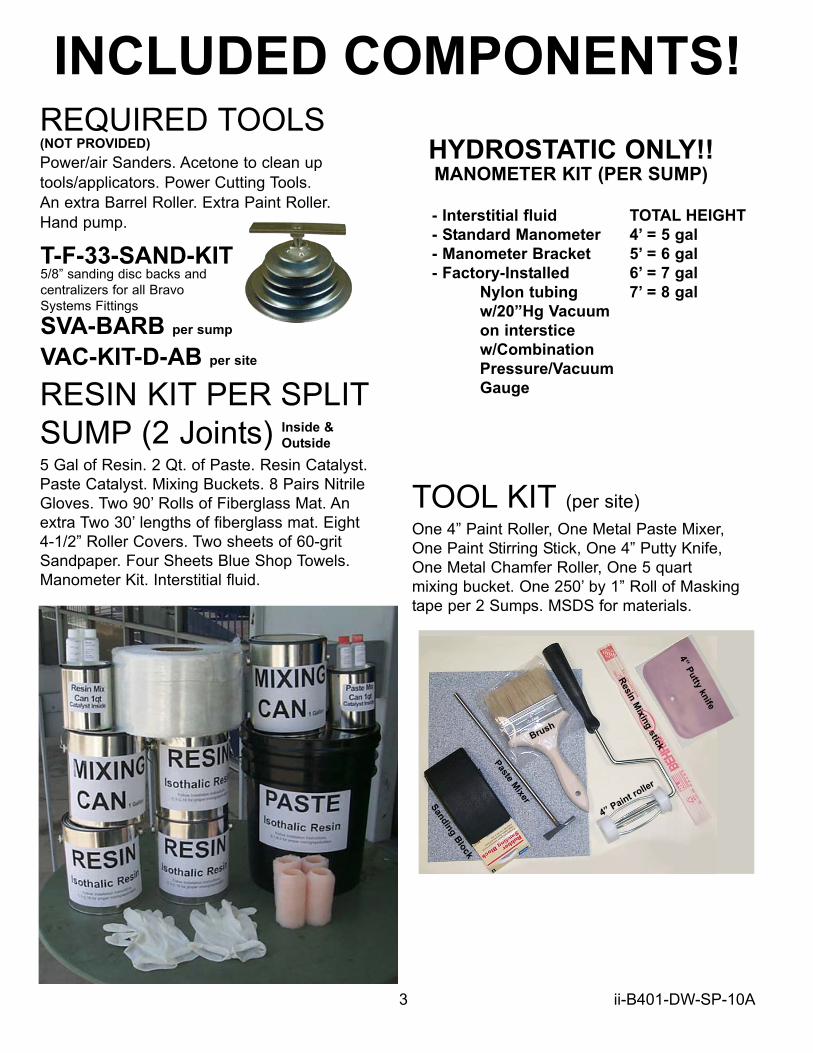
H - FIBERGLASSING THE BODY TO BASE
ENSURE THAT THE SUMPS ARE COMPLETELY DRY, FREE OF
DEBRIS, ICE AND/OR SNOW. DO NOT HANDLE ANY FIBERGLASS
SUMP WITH YOUR BARE HANDS.
H.1 - Pre-cut several dozen pieces of 6” wide fiberglass mat to lengths of 20-24”. You will need
4 layers of these fiberglass mat strips for the INSIDE and OUTSIDE joints of each piping sump.
H.2 - Mix together resin and catalyst with mix stick thoroughly.
For SUMMER!! 1/4 bottle per 1/4 Gallon of resin.
For WINTER!! 1/2 bottle per 1/4 Gallon of resin.
H.3 - Use paint roller to apply resin generously to a smooth surface.
Spread the resin so it ‘wets out’ an area larger than the strip of fiberglass
mat. (Fig. H.3)
H.4 - Apply one layer of fiberglass mat to the resin and use the paint
roller to add more resin to fully saturate it. (Fig. H.4)
H.5 - Lay down another strip of fiberglass mat, staggering the new layer
ONE INCH. This means to offset the next fiberglass strip horizontally
(lengthwise) 1” to the right. Roll more resin into the new strip to saturate it.
(Fig. H.5)
H.6 - Repeat Step H.5, offsetting another
strip of fiberglass mat and using the paint
roller to add more resin to it until it is fully
saturated. (Fig. H.6)
H.7 - Repeat Step H.5 once more, for a
total of 4 Layers of fiberglass.
H.8 - Use a Chamfer roller to completely roll over the pre-soaked
fiberglass strip while it is on the cardboard, horizontally and vertically,
to run out any air bubbles. (Fig. H.6)
H.9 - Apply the fiberglass patch to the OUTSIDE JOINT of the piping
sump centered on the joint. Apply saturated fiberglass strips all the way
around the piping sump....EVENLY OVERLAPPING EACH 2 FOOTSTRIP 3 INCHES OVER THE LAST. (Fig. H.9.1)
Fig. H.4
Fig. H.3
Fig. H.5
Fig. H.6
Layer 1
Layer 2
Layer 3
14
Paint roller
Chamfer
roller
Paint roller
ii-B401-DW-SP-10A

ONLY apply fiberglass strips horizontally (ACROSS the piping sump, not up and down.)The completed glass job should be air-free, seamless and ripple-free as shown in Fig. H.9.3.
Roll over the fiberglass mat many times with a Chamfer roller (provided) on the OUTSIDE JOINT
to make sure it is cleanly adhered to the fiberglass piping sump walls. Run the roller up and down to
force any air out from under the fiberglass strip. (Fig. H.9.2)
H.10 - Repeat Steps H.4 to H.9 and apply fiberglass strips to the INSIDE JOINT of the piping
sump. (Fig. H.10.1) For the INSIDE fiberglass strips use a Barrel roller to apply the strips to the
curved surface. (Fig. H.10.2)
H.11 - Use a Chamfer roller to carefully roll over the applied fiberglass strips to run out any air
bubbles. (Fig. H.11)
H.12 - Allow at least 4 hours at 75 Degrees to cure. During this time, continue on to other sumps.
H.13 - When all fiberglass applications have cured, sand them down
lightly with air-sander or roughly with coarse 40 - 60 grit sandpaper all
the way around the piping sump to knock down all excess fiberglass ‘hair’
and material. (Fig. H.13)
H.14 - Mix resin and apply with paint roller, completely covering the
fiberglass material all the way around the piping sumps. Roll resin generously
with paint roller. DO NOT USE PUTTY KNIFE or other scraping tool.
The resin needs to be applied generously and evenly. (Fig. H.14)
H.15 - Now install any other equipment in the piping sump(s) that was not
installed yet. Install all necessary equipment per local code & regulations.
Follow installation instructions / recommendations / warnings provided by
equipment manufacturer(s).
3” Overlap
15
Fig. H.9.2Fig. H.9.1
Fig. H.9.3
Fig. H.10.1 Fig. H.10.2 Fig. H.11
ii-B401-DW-SP-10A
Fig. H.13
Fig. H.14
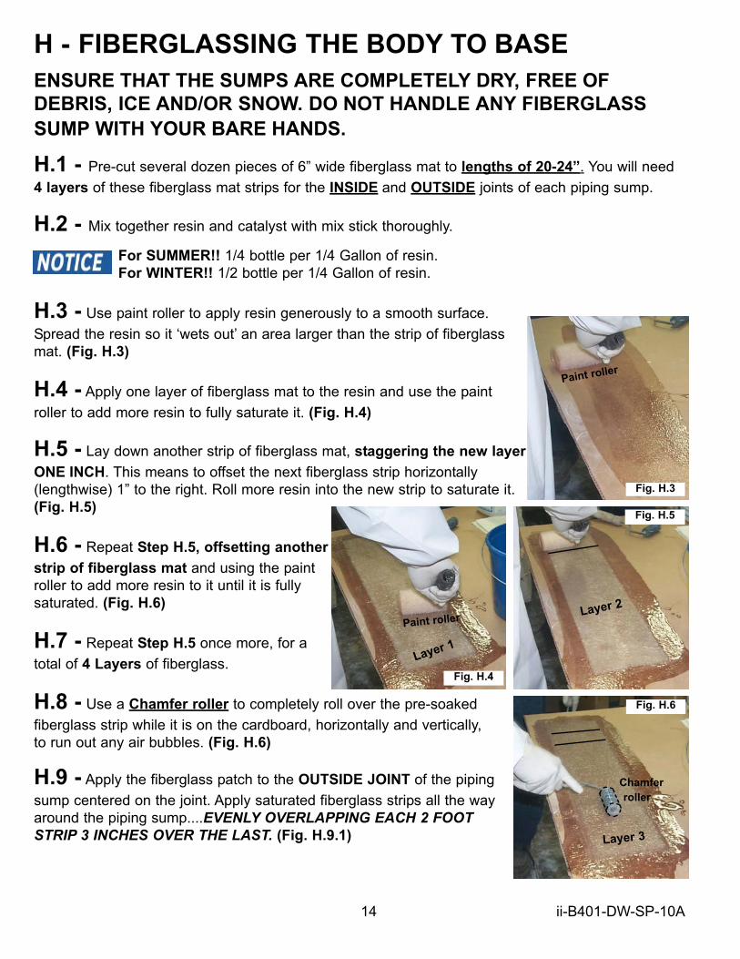
I - MANDATORY AIR
INTEGRITY TEST
I.1 - Use test assembly and pressure sump to no more
than 4 PSI. Close off with ball valve and resume other work.
Allow 1 Hour before recording pressure.
FIELD AIR INTEGRITY INSPECTION TEST : Hold pressure for a
minimum of 1 hour for a Field Integrity Inspection Test. The Tank Sump PASSESthe integrity test if the Sump shows NONO signs of continuous pressure decay.
IF TEST PASSES - CONTINUE ON TO THE HYDROSTATIC FILL & INTEGRITY TEST.
I.2 - IF ANY LEAKS ARE FOUND!!
Occasionally... Bravo Fiberglass Series Products may suffer mild damage in transit or field
installation. Look at edges and corners for pinhole leaks. For large leaks, consult factory.
A: Locate leak point(s) and mark with marker so you can locate it / monitor it.
B: Repair or reinstall doublewall penetration fittings according to your doublewall penetration
fitting manufacturers’ Installation / Maintenance Instructions.
C: Abrade a 2” diameter area centered on the leak point until natural resin/fiberglass material
can be seen. Dust with shop brush or compressed air and do not use shop towels or
acetone on the abraded area(s). Then apply a 3-layer strip of 2” x 2” resin-saturated
fiberglass mat squarely on the abraded area.
D: Roll out any air bubbles with chamfer roller. Let cure.
E: After cure, knock down fiberglass hairs, and apply another flow coat of
resin only (Step H.15). Apply any extra resin to repaired leak point(s) while still wet.
Let cure for a minimum of 4 hours @ or above 75° F.
FOR HYDROSTATIC MONITORING - PROCEED TO SECTION J.
FOR CONTINUOUS VACUUM MONITORING - The B400 DoubleWall
Split Series Sump cannot exceed 16” of Mercury. (Vacuum) Follow
your vacuum system manufacturer’s installation instructions to
install, seal, and monitor the doublewall system with vacuum.
Continue to Section M.
Ensure that the fittings that are being used with theVacuum Monitored System can withstand the amount
of Vacuum your Monitoring System will generate.16
BRAVOQUALITY
STANDARD
ii-B401-DW-SP-10A
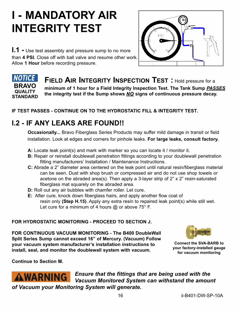
Connect the SVA-BARB to
your factory-installed gauge
for vacuum monitoring

J - VACUUM / HYDROSTATIC FILLING
FIELD AIR INTEGRITY INSPECTION TEST :
YOUR PRODUCT WARRANTY WILL BE VOID IF YOU DO NOT Hold pressure
for a minimum of 1 hour for a Field Integrity Inspection Test. After passingthe pressure test, it is HIGHLY RECOMMENDED that the 4 PSI is maintained for as long as possible, up until the time of backfill.
YOUR PRODUCT WARRANTY WILL BE REVOKED IF YOU
CHOOSE TO SKIP THE AIR INTEGRITY TEST OUTLINED IN YOUR
COPY OF YOUR PRODUCT INSTALLATION INSTRUCTIONS. YOU MUST COMPLETE THE
PRESSURE TEST PRIOR TO HYDROSTATIC FILLING OF THE SUMPS.
The Bravo Double Wall product’s ship from the factory with a combination gauge factory- installed
and held under 20” of mercury / vacuum.
J.1 - After passing the Field Air Integrity Test per the Installation Instructions and there are no
signs of leaks, you must cut the permanently affixed pipe plug from the tubing connected to the side
wall. This is NOT the tubing with the gauge connected to it.
J.2 - Connect (newly cut) open end of tubing to barb-and-ball-valve assembly. (sold seperately)
A 36” length of clear tubing is factory installed to the barb-and-ball-valve assembly.
After the penetration
fittings have been
installed, the vacuum has
been lost. Pressure/soap
tests should have been
conducted prior to filling
the sumps with liquid.
Barb & Ball Valve
AssemblyCut Plug end off
from tubing
Connect
Assembly to
tubing
You must cut off the barbed
plug and connect the
provided Barb & Ball Valve
Assembly. Close off the ball
valve and prepare the
Venturi Vacuum Generator
and air supply to be used to
fill Sump with liquid.
17 ii-B401-DW-SP-10A

18
J.3 - Close off ball valve completely and prime
the open ended 36” length of clear tubing with
provided Interstitial Fluid. Use a liquid funnel.
Filling Bravo Systems DoubleWall Products with Brine (saline) solutionwill void the product warranty. You must use only Bravo-Supplied Interstitial Fluid, part # IMF-1GAL
J.4 - After filling the tubing all the way to the ball valve, insert open end into your liquid source.
(5 gallon bucket filled with fluid is recommended.)
J.5 - When ready, pull vacuum using the Venturi Vacuum Assembly (sold seperately) to 20 Inches
of mercury. Then SLOWLY open ball valve and allow Interstitial fluid to flow freely into the system at a
rate of about 2 gallons a minute.
...SLOWLY open ball valve...J.6 - STOP PULLING VACUUM WHEN THE LIQUID IS 2-3 INCHES FROM THE VERY TOP OF
THE INTERSTITIAL SPACE / TEST PORT. This is easily visible while filling the DoubleWall Product.
After liquid fill, Conduct the
Advanced Leak Detection
Procedure, then Cut the ball
valve assembly from its tubing
and connect open end of tubing
to Primary manometer. Also
unthread the Gauge Assembly
and use provided PVC threaded
plug to close off open test port
fitting.
Barb &
Ball Valve
Assembly
Bucket
Venturi Vacuum Generator
ii-B401-DW-SP-10A

K) ADVANCED LEAK DETECTION
PROCEDUREA Bravo Systems Exclusive detection method
K.1 - Clear debris from the top open area of the DoubleWall Product and ensure that the
interior walls are clean of debris and visible.
K.2 - Apply Vacuum to the sealed interstitial space with the Venturi Vacuum Assembly, and
generate 20”-30” of vacuum for a MINIMUM of Five [ 5 ] Minutes.
K.3 - As stated in your Instructions, the liquid level is deliberately not filled to the very top
of the interstitial space. This pocket of air is necessary to visually check the topmost level of
liquid all the way around the Sump for indication of a leak.
K.4 - Visually inspect the interior walls for signs of trailing (very small) bubbles floating to
the top of the liquid level within the interstitial space.
These air bubbles are visible within the vertical and horizontal
channels of the walls. For Tank Sumps look below the reducer.
On the top hat reducer of a Tank Sump, any bubbles will burp
consistently.
PAY CLOSE AND SPECIAL ATTENTION TO FIELD-INSTALLED
PENETRATION FITTINGS and FRP JOINTS ON TANK SUMPS.
THESE ARE COMMON LEAK POINTS.
CHECK WITH YOUR EQUIPMENT MANUFACTURERS
INSTALLATION MANUALS FOR INSTALLATION
GUIDELINES AND/OR EQUIPMENT LIMITS REGARDING
VACUUM AND PRESSURE LEVELS.
Even though Bravo DoubleWall product corners and edges are thicker than the rest of the
Containment sump, These areas recieve the most supceptable to physical damage by Installing
Contractors. You would do well to be extremely careful with these DoubleWall products while storing,
moving, transporting and Installing these critical environmental components.
19 ii-B401-DW-SP-10A
Even though Bravo DoubleWall product corners and edges are thicker than the rest of the
Containment sump, These areas recieve the most supceptable to physical damage by Installing
Contractors. You would do well to be extremely careful with these DoubleWall products while storing,
moving, transporting and Installing these critical environmental components.
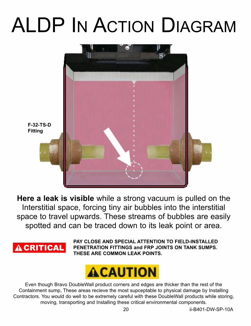
Here a leak is visible while a strong vacuum is pulled on theInterstitial space, forcing tiny air bubbles into the interstitial
space to travel upwards. These streams of bubbles are easilyspotted and can be traced down to its leak point or area.
ALDP IN ACTION DIAGRAM
PAY CLOSE AND SPECIAL ATTENTION TO FIELD-INSTALLED
PENETRATION FITTINGS and FRP JOINTS ON TANK SUMPS.
THESE ARE COMMON LEAK POINTS.
20 ii-B401-DW-SP-10A
F-32-TS-D
Fitting

L - ATTACHING THE MANOMETERL.1 - At this point, after the ALDP test, the interstice should still be holding vacuum. Maintain 20” ofVacuum and slowly open ball valve to let fluid into the interstice until it exits the venturi assembly.Visually check whether the fluid level reaches the top of the interstitial space.
L.2 - Cut the barb & ball valve assembly free by cutting the tubing just below it and connect open
end of tubing to the bottom of the primary Manometer.
L.3 - Remove the Barb, Tubing & Combination gauge assembly from the test port fitting on the
side of the sump. Install a threaded pipe plug into the open test port fitting and adjust Primary
manometer bracket so the manometer is in a position clear of the sump cover.
Remove Entire Gauge
Assembly by backing
off threaded barb fitting.
Cut off barb
& ball valve
assembly.
Install PVC Plug
Connect Tubing to
Primary Manometer
P-Traps OK since vacuum fill
method leaves no room for air.
L.4 - It is not uncommon for some interstitial fluid to be lost while connecting the tubing to the primary
manometer. This is ok. Replace lost fluid by topping off manometer with interstitial fluid until the liquid level
reaches just 2 inches below the top of manometer.
L.5 - Hydrostatic Field Integrity Test - Mark the date and time of test and
manometer level. Allow 1 hour to look for a change in level. No change in level or visible leaking means
box passes test.
L.6 - If interstitial test fluid changes its level more than 1/4”, visually look for any signs of leaking around
fittings both interior and exterior to sump. Pay special attention to field installed fittings.
L.7 - If interstitial monitoring is required, install a California Listed Hydrostatic Sensor (LG-113) using the
sensor manufacturer’s fitting. Run sensor cable through the cap assembly (see Fig. L.7). Level sensor should
be set to bottom of manometer. Follow your leak detector manufacturer’s installation instructions. Cover the
manometer with cap and fasten with wire and lead crimp seal.
Continuous Monitoring
Interstitial & Leak
Detection of Secondary
Containment
Sensor Cable
Cap assembly
Fig. L.7
21 ii-B401-DW-SP-10A

22 ii-B401-DW-SP-10A
M - Concrete and Backfill Guidelines.To ensure that no immediate or future damage is done to your Bravo Tank Sump Reducer
components, make sure that your manhole skirt DOES NOT TOUCH OR REST ON THE TANK
SUMP SHOULDER. The Manhole Skirt should be kept at minimum of 4” away from the tank sump
shoulder. Follow the manhole manufacturers instructions for installing the manhole. Also follow other
details provided by tank and/or engineering firm for tank driveway pad installation.
Backfill your peagravel around the sump maintaining a minimum of 1’ foot all the way around (if your
site backfill is not entirely peagravel) and 4” minimum distance from the top edge of sump reducer.
When peagravel is in place, use a 3mil or thicker plastic sheet to cover the surface of the peagravel
no less than 2 feet away from the sump reducer wall.
Secure this plastic barrier to the EXTERIOR OF THE MANHOLE SKIRT using duct tape.
This prevents concrete from seeping too far down
into the peagravel.
Manhole Cover
CONCRETE
SLAB
Manhole skirt
Sump Cover
Min 1’ foot
peagravel all
around sump
1” to 1-1/2”
Distance
3mil+ Plastic Barrier
taped to manhole skirt
SAND
OR
SOIL
Minimum
4 inchesbetween top
of sump
reducer and
peagravel
Manhole
skirt min.
4” away
from Tank
sump
shoulder