Embed Size (px)
Citation preview
—I N S TA LL ATI O N I N S TR U C TI O N
Switch DisconnectorsOT1600E_-135
—
Swit
ch D
isco
nnec
tors
34O
T16
00
-135
rev
. B/
1SC
C30
110
0M
020
1
2 S W ITCH D I S CO N N EC TO R S , OT 16 0 0 _ -1 3 5
— Table of contents003 Installation
004 Label Terminal clamps, OZX_
005 TerminalshroudsOTS_
006 Circuits&Barrierinstallation
007 Connectionkits,OTB_
008 OT1600E_-135Switchesratingsandsupporting distancesforbusbarandcableconnections
009 AuxiliarycontactsOA_
010 Auxiliarycontactswiring
011 ModuleforauxcontactsOEA28
012 DirectmounthandleOTV_
013 InterlockingOTZT4
014 Dimensionaldrawings
015 Warningtable
3S W ITCH D ISCO N N EC TO R S , OT 16 0 0 _ -1 3 5
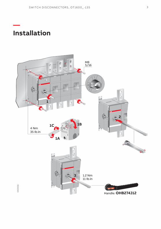
—Installation
M85/16
4 Nm35 Ib.in
KA
00
016
1
1C
1A
1B
Handle: OHB274J12
1.2 Nm11 Ib.in
3
00
2
4 S W ITCH D I S CO N N EC TO R S , OT 16 0 0 _ -1 3 5
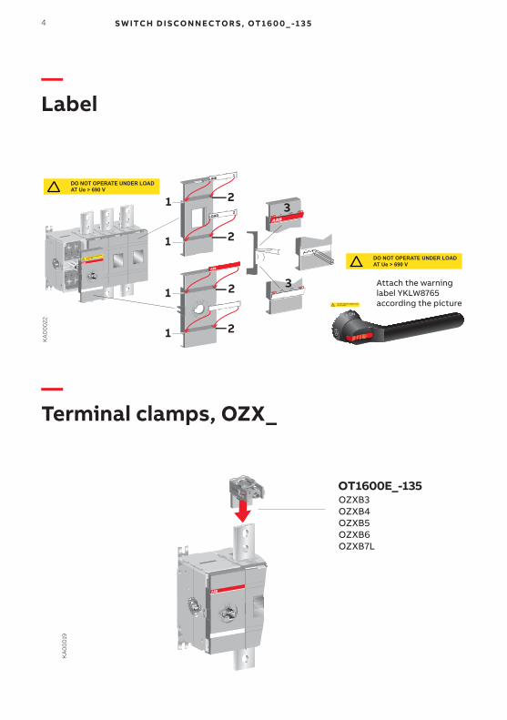
—Label
—Terminal clamps, OZX_
KA
00
019
OT1600E_-135 OZXB3OZXB4OZXB5OZXB6OZXB7L
LINE1
LOAD2
1 23
3
1
1
1
2
2
2
KA
00
022
Attach the warning label YKLW8765 according the pictureDO NOT OPERATE UNDER LOAD
AT Ue > 690 V
DO NOT OPERATE UNDER LOADAT Ue > 690 V
DO NOT OPERATE UNDER LOAD
AT Ue > 690 V
DO NOT OPERATE UNDER LOADAT Ue > 690 V
5S W ITCH D ISCO N N EC TO R S , OT 16 0 0 _ -1 3 5
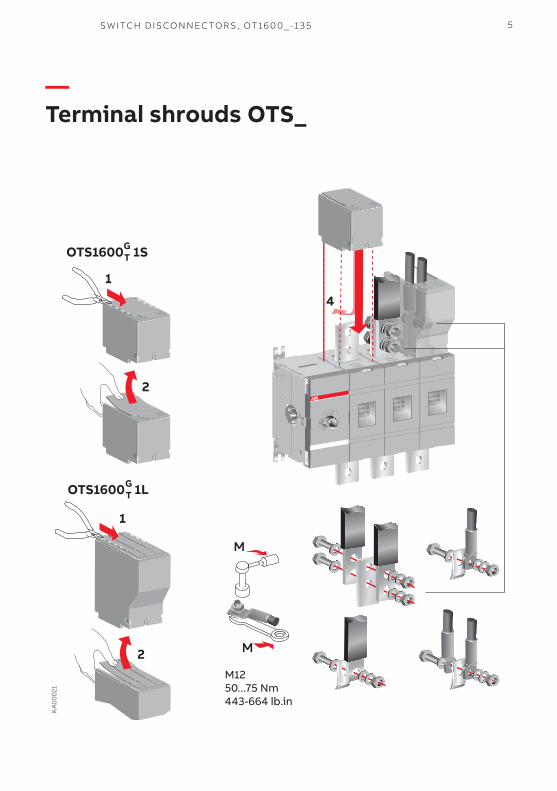
—TerminalshroudsOTS_
OTS1600 1SGT
OTS1600 1LGT
KA
00
021
M1250...75 Nm443-664 lb.in
M
M
2
1
1
2
4
6 S W ITCH D I S CO N N EC TO R S , OT 16 0 0 _ -1 3 5
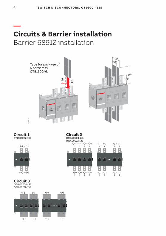
—Circuits&BarrierinstallationBarrier 68912 installation
+ (–) – (+)+(–) –(+) +(–) –(+) +(–) –(+) +(–) –(+)
+(–) –(+) +(–) –(+) +(–) +(–) +(–) –(+)– (+)+ (–)
+(–) –(+) +(–) –(+)
+(–) –(+) +(–) –(+)
1 1 2 2 1 1 2 2
1 1 22 221 1
Circuit 1OT1600E02-135
Circuit 2OT1600E04-135OT1600E22-135
Circuit 3OT1600E04-135OT1600E22-135
KA
00
020
Type for package of6 barriers isOTB1600/6.
12
167
170
100
127
7S W ITCH D ISCO N N EC TO R S , OT 16 0 0 _ -1 3 5
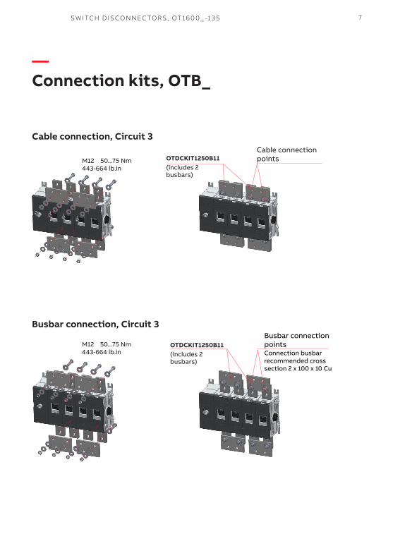
—Connectionkits,OTB_
Cableconnection,Circuit3
Busbarconnection,Circuit3
OTDCKIT1250B11 (includes 2 busbars)
M12 50...75 Nm443-664 lb.in
Cable connection points
M12 50...75 Nm443-664 lb.in
Busbar connection pointsConnection busbar recommended cross section 2 x 100 x 10 Cu
OTDCKIT1250B11 (includes 2 busbars)
8 S W ITCH D I S CO N N EC TO R S , OT 16 0 0 _ -1 3 5
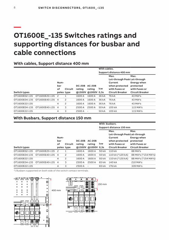
—OT1600E_-135Switchesratingsand supportingdistancesforbusbarand cable connections
Switchtypes
Num- ber of poles
Circuittype
DC-20Brating@1500V
AC-20Brating@1000V
Withcables. Supportdistance400mm
lcw 0,3s
Max. Let-throughPeakCurrent whenprotectedwithFusesor CircuitBreaker
Max. Let-throughEnergywhenprotected withFusesorCircuitBreaker
OT1600E02-135 OT1600E20-135 2 1 1600 A 1600 A 36 kA 76 kA 43 MA2s
OT1600E04-135 OT1600E40-135 4 2 1600 A 1600 A 36 kA 76 kA 43 MA2s
OT1600E22-135 4 2 1600 A 1600 A 36 kA 76 kA 43 MA2s
OT1600E04-135 OT1600E40-135 4 3 2500 A 2500 A 50 kA 105 kA 115 MA2s
OT1600E22-135 4 3 2500 A - 50 kA 105 kA 115 MA2s
Switchtypes
Num- ber of poles
Circuittype
DC-20Brating@1500V
AC-20Brating@1000V
Withbusbars. Supportdistance150mm
lcw 0,3s
Max. Let-throughPeakCurrent whenprotectedwithFusesor CircuitBreaker
Max. Let-throughEnergywhenprotected withFusesorCircuitBreaker
OT1600E02-135 OT1600E20-135 2 1 1600 A 1600 A 50 kA 110 kA 88 MA2s
OT1600E04-135 OT1600E40-135 4 2 1600 A 1600 A 50 kA 110 kA (*120 kA) 88 MA2s (*154 MA2s)
OT1600E22-135 4 2 1600 A 1600 A 50 kA 110 kA (*120 kA) 88 MA2s (*154 MA2s)
OT1600E04-135 OT1600E40-135 4 3 2500 A 2500 A 65 kA 140 kA 210 MA2s
OT1600E22-135 4 3 2500 A - 65 kA 176 kA 339 MA2s
Withcables,Supportdistance400mm
WithBusbars,Supportdistance150mm
400 mm
150 mm
*) Busbars supported on both side of the switch contact terminals
9S W ITCH D ISCO N N EC TO R S , OT 16 0 0 _ -1 3 5
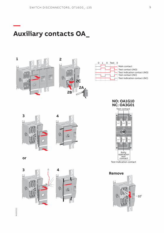
—AuxiliarycontactsOA_
KA
00
023
43
0 1 0 Test 0
Main contactTest contact (NO)Test indication contact (NO)Test contact (NC)Test indication contact (NC)
Remove3
or
2
4
10
NO: OA1G10NC: OA3G01
Test contact
Test indication contact
MAX 2 MAX 2MAX 2
MAX 2 MAX 2MAX 2
TEST IND.TEST IND.
Early operation
test contact
1
2C
2A2B
10 S W ITCH D I S CO N N EC TO R S , OT 16 0 0 _ -1 3 5
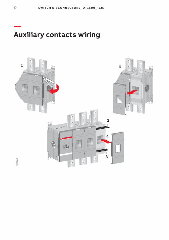
—Auxiliarycontactswiring
KA
00
035
1 2
3
4
3
11S W ITCH D ISCO N N EC TO R S , OT 16 0 0 _ -1 3 5
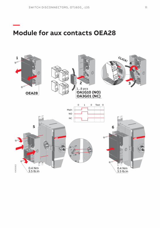
—ModuleforauxcontactsOEA28
OEA281...8 pcsOA1G10 (NO)OA3G01 (NC)
KA
00
063
Main
NO
NC
0 1 0 Test 0
0.4 Nm3.5 lb.in
0.4 Nm3.5 lb.in
CLICK!1
2 3
4
5 6
12 S W ITCH D I S CO N N EC TO R S , OT 16 0 0 _ -1 3 5
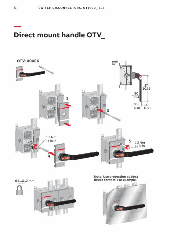
—DirectmounthandleOTV_
OTV1000EK
1,2 Nm11 lb.in 1,2 Nm
11 lb.in
Note: Use protection against direct contact. For example:Ø5...Ø10 mm
27410.79
903.54
1064.18
150.59
mmin
1
2
3
4
5
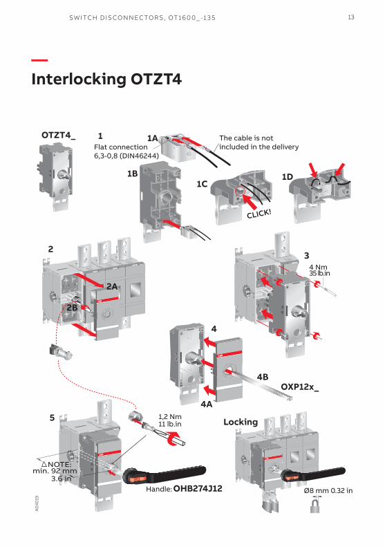
13S W ITCH D ISCO N N EC TO R S , OT 16 0 0 _ -1 3 5
—InterlockingOTZT4
OTZT4_
CLICK!
4 Nm 35 lb.in
A0
4019
Locking
Ø8 mm 0.32 in
1,2 Nm11 lb.in
Handle: OHB274J12
NOTE:min. 92 mm
3.6 in
1 1A
1B1C
1D
2
2A
2B
3
4
4A
OXP12x_4B
5
Flat connection6,3-0,8 (DIN46244)
The cable is not included in the delivery
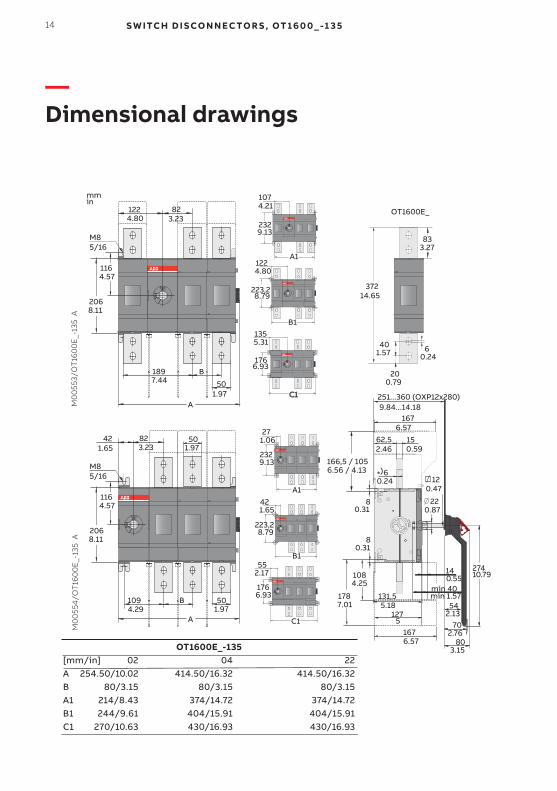
14 S W ITCH D I S CO N N EC TO R S , OT 16 0 0 _ -1 3 5
—Dimensionaldrawings
200.79
401.57
62,52.46
150.59
140.55
120.47
220.87
127
178
108
8
min 40min 1.57
166,5 / 1056.56 / 4.13
mmin
60.24
60.24
OT1600E_
37214.65
51676.57
7.01
4.25
0.31
80.31
*)
1676.57
251...360 (OXP12x280)9.84...14.18
3.2783
1224.80
823.23
1164.57
2068.11
1897.44
A
501.97
M0
055
3/O
T16
00
E_-
135
AM
00
554
/OT
160
0E
_-13
5 A
M85/16
B
223,2
122
B1
8.79
4.80
176
135
C1
5.31
6.93
232
107
A1
4.21
9.13
421.65
823.23
1164.57
2068.11
1094.29
A
B
M85/16
501.97
223,2
B1
8.79
1.65
176
55
C1
2.17
6.93
42
232
27
A1
1.06
9.13
501.97
131,55.18 54
80
70
27410.79
2.13
2.76
3.15OT1600E_-135[mm/in] 02 04 22A 254.50/10.02 414.50/16.32 414.50/16.32B 80/3.15 80/3.15 80/3.15A1 214/8.43 374/14.72 374/14.72B1 244/9.61 404/15.91 404/15.91C1 270/10.63 430/16.93 430/16.93
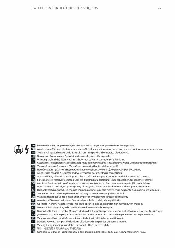
15S W ITCH D ISCO N N EC TO R S , OT 16 0 0 _ -1 3 5
CZ

—Contactus
ABBOy P.O. Box 622
FI-65101 Vaasa
Finland
abb.com/lowvoltage
© Copyright 2018 ABB. All rights reserved. Specifications subject to change without notice. 3
4O
T16
00
-135
rev
. B/
1SC
C30
110
0M
020
1 #
28
.12.
2018