Embed Size (px)
Citation preview
“Keeping You Cool Under Pressure”
Installation Instruction for ’92-’93 GM 6.5L Turbo Diesel Series 3500 -4 Wheel Drive Pickup and
Series 1500, 2500, 3500 – 4 Wheel Drive SuburbanIntercooler System (Part No. 2-436)
TOOLS REQUIRED:1.) Normal complement of mechanic’s hand tools2.) Electric drill3.) _” and 7/16” diameter drill bits4.) Jack and jack stands5.) Permatex red silicone
INSTALLATION:1.) Remove the following:
a. Brace from compressor housing to intake manifoldb. Plastic cover over intake manifoldc. Oil breather tubed. Intake manifold extension castinge. Convoluted air duct from air cleaner to turbo inletf. Turbo compressor housing
Remove six 8mm bolts, retaining plates and wastegate on the backside of thecompressor housing. Leave wastegate rod connected to the lever arm. Tap offthe compressor housing, making certain it comes off straight and does not getcocked. The compressor housing is factory-assembled with three-bond sealantso it will be hard to break free.
CAUTION: There is only 0.020 clearance between the housing and the impeller and if it gets cocked and angled coming off, it can bend and damage the compressor wheel.
2.) Remove Intake Manifold Extension and Install Modified Shortened Unit with New GasketOn 1994 models, remove M.A.P. sensor and 3/8” NPT threaded sensor and install in newpart. On 1993 models, plug the 3/8” hole with the pipe plug provided and drill the othersensor hole 7/16” diameter and tap _” NPT and plug with pipe plug provided.
3.) Re-install Compressor HousingClean all adhesive from the groove in the back side and also on the mating plate. Applya thin film of Permatex Red Silicone and re-install on the turbo, rotating about 120% fromthe original position, or to about 7:00 o’clock position. Exact position is determined by thenew brace, which goes under the three top bolts and replaces the three small tabs. Oncealignment is correct, re-attach the wastegate and use existing tabs under remaining bolts,tighten all bolts and retain the brace with 5/16-18 X 1” bolt and special, heat resistant locknut provided.
“Keeping You Cool Under Pressure”
CAUTION: Make sure the compressor housing goes straight on and is not cocked. After it is tight, spin the turbo to be sure it is free.
4.) Relocate Heater HoseThe heater hose is retained at the inner fender with a plastic holder. Snap open theholder and remove the bottom hose, and snap back. With a wire tie provided, positionthe hose on the top of the retainer in such a way as to provide more clearance betweenthe turbo and hoses.
5.) Relocate Battery CableOn the right side, on top of the frame, the battery cable is retained on the inside edge ofthe frame with a clip and bolt. Remove the bolt, take the clip off the cable, reverse it, re-install and flatten it. This provides additional clearance for the turbo for the turbo.
6.) Installation of IntercoolerIf your vehicle is equipped with two hooks bolted to the front bottom of the frame, removethe bolts and hooks and place the 1/8” thick intercooler mounting plates under the hooksand bolt back into position. Leave one side loose at this time. Hold the intercoolerassembly into position with the angle bracket sitting on top of the plates. Loosen onepiece, swing it clear and slide the intercooler up and swing the plate back. Check theposition and alignment of the _” diameter holes and tighten plate into position. If yourtruck has no hooks, mount the plates with bolts (7/16-14 X 1”), lock nuts and flat washersand _” thick steel backup plates provided.
7.) Bolting Intercooler Assembly to Mounting PlatesFour _-20 X _” bolts, lock nuts and washers (for the bottom) are provided. Install andtighten them and then back off _ turn.
CAUTION: Be sure to back off _ turn, as this will provide some compliance for frame deflection to eliminate the possibility of pulling the intercooler apart.
8.) Installation of Intercooler TubesTo provide clearance for the tubes, the transmission cooler lines must be pulled up about1”. This is done by pulling them loose from the retaining clip on the bottom right handside of the engine. 1994 models with the vacuum pump mounted on the right hand sideof the engine have a different routing for the transmission cooler lines. On these modelsit is necessary to remove the line-retaining clip that is held in place by one oil pan boltnear the right hand side rear of the pan.
“Keeping You Cool Under Pressure”
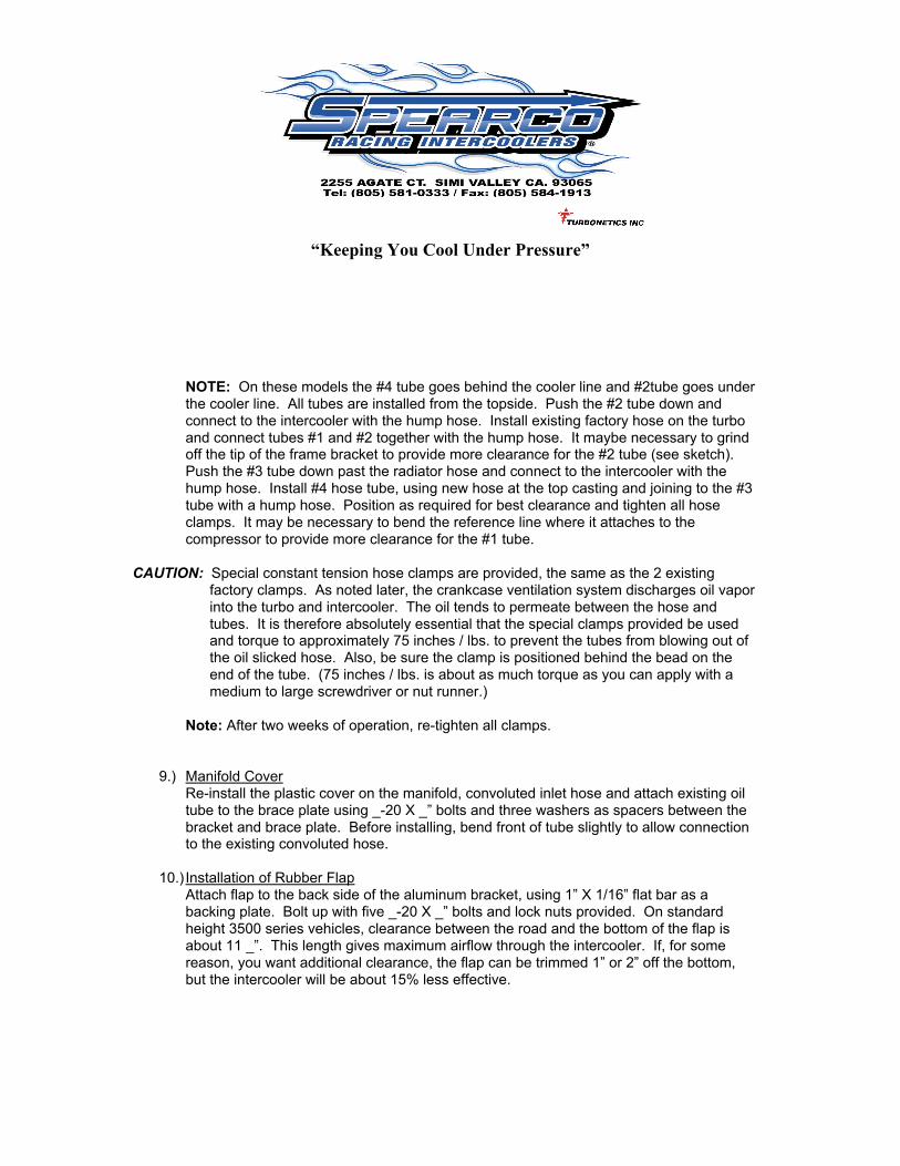
NOTE: On these models the #4 tube goes behind the cooler line and #2tube goes underthe cooler line. All tubes are installed from the topside. Push the #2 tube down andconnect to the intercooler with the hump hose. Install existing factory hose on the turboand connect tubes #1 and #2 together with the hump hose. It maybe necessary to grindoff the tip of the frame bracket to provide more clearance for the #2 tube (see sketch).Push the #3 tube down past the radiator hose and connect to the intercooler with thehump hose. Install #4 hose tube, using new hose at the top casting and joining to the #3tube with a hump hose. Position as required for best clearance and tighten all hoseclamps. It may be necessary to bend the reference line where it attaches to thecompressor to provide more clearance for the #1 tube.
CAUTION: Special constant tension hose clamps are provided, the same as the 2 existing factory clamps. As noted later, the crankcase ventilation system discharges oil vapor into the turbo and intercooler. The oil tends to permeate between the hose and tubes. It is therefore absolutely essential that the special clamps provided be used and torque to approximately 75 inches / lbs. to prevent the tubes from blowing out of the oil slicked hose. Also, be sure the clamp is positioned behind the bead on the end of the tube. (75 inches / lbs. is about as much torque as you can apply with a medium to large screwdriver or nut runner.)
Note: After two weeks of operation, re-tighten all clamps.
9.) Manifold CoverRe-install the plastic cover on the manifold, convoluted inlet hose and attach existing oiltube to the brace plate using _-20 X _” bolts and three washers as spacers between thebracket and brace plate. Before installing, bend front of tube slightly to allow connectionto the existing convoluted hose.
10.) Installation of Rubber FlapAttach flap to the back side of the aluminum bracket, using 1” X 1/16” flat bar as abacking plate. Bolt up with five _-20 X _” bolts and lock nuts provided. On standardheight 3500 series vehicles, clearance between the road and the bottom of the flap isabout 11 _”. This length gives maximum airflow through the intercooler. If, for somereason, you want additional clearance, the flap can be trimmed 1” or 2” off the bottom,but the intercooler will be about 15% less effective.
“Keeping You Cool Under Pressure”
Installation is now complete. Double check that all clamps are behind the beads on the tubes.Double check that there is no interference with the battery cable or other wiring, etc. Check thatthere is clearance between the steering gear idler and the intercooler tubes at right hand full lock.If any interference is noted, loosen clamps and re-arrange tubes as necessary to provideminimum 3/8” clearance. Make certain that no foreign material has entered the turbo or intakemanifold and make sure the _” intercooler plate mounting bolts are backed off _ turn to preventdamage to the intercooler.
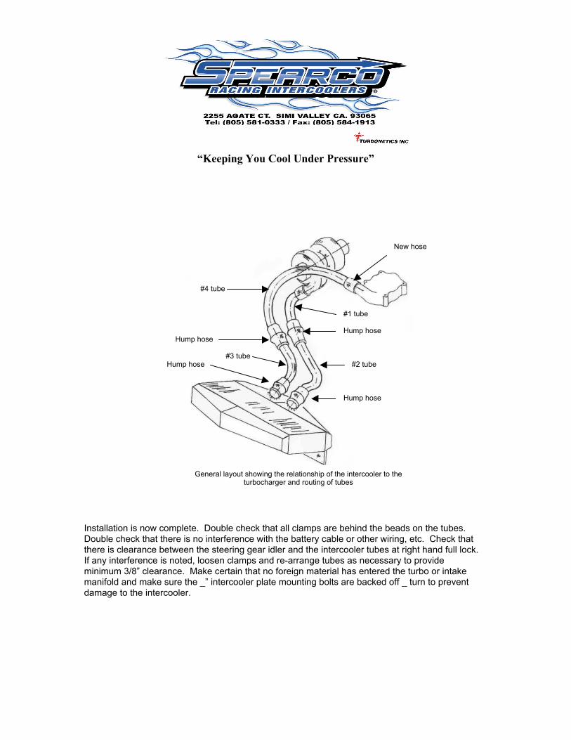
New hose
Hump hose
Hump hose
Hump hose
Hump hose #2 tube
#1 tube
#3 tube
#4 tube
General layout showing the relationship of the intercooler to theturbocharger and routing of tubes
“Keeping You Cool Under Pressure”
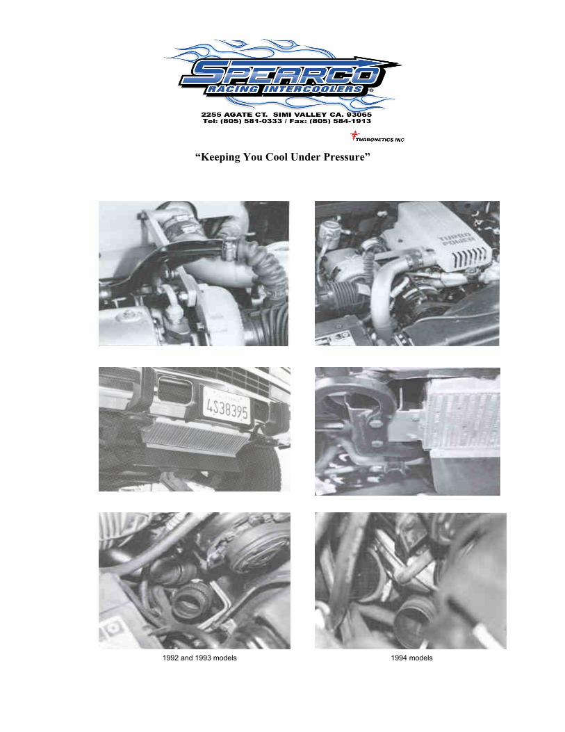
1992 and 1993 models 1994 models