Embed Size (px)
Citation preview
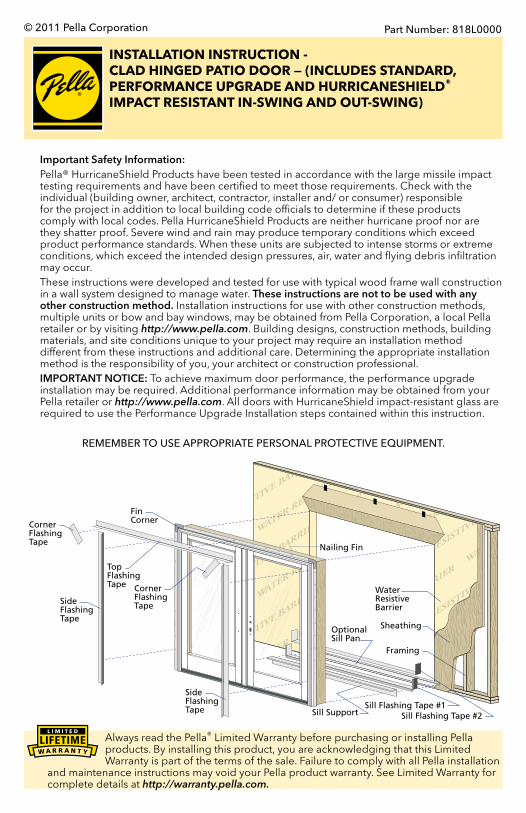
INSTALLATION INSTRUCTION - CLAD HINGED PATIO DOOR — (INCLUDES STANDARD, PERFORMANCE UPGRADE AND HURRICANESHIELD® IMPACT RESISTANT IN-SWING AND OUT-SWING)
Part Number: 818L0000© 2011 Pella Corporation
Important Safety Information: Pella® HurricaneShield Products have been tested in accordance with the large missile impact
testing requirements and have been certified to meet those requirements. Check with the individual (building owner, architect, contractor, installer and/ or consumer) responsible for the project in addition to local building code officials to determine if these products comply with local codes. Pella HurricaneShield Products are neither hurricane proof nor are they shatter proof. Severe wind and rain may produce temporary conditions which exceed product performance standards. When these units are subjected to intense storms or extreme conditions, which exceed the intended design pressures, air, water and flying debris infiltration may occur.
These instructions were developed and tested for use with typical wood frame wall construction in a wall system designed to manage water. These instructions are not to be used with any other construction method. Installation instructions for use with other construction methods, multiple units or bow and bay windows, may be obtained from Pella Corporation, a local Pella retailer or by visiting http://www.pella.com. Building designs, construction methods, building materials, and site conditions unique to your project may require an installation method different from these instructions and additional care. Determining the appropriate installation method is the responsibility of you, your architect or construction professional.
IMPORTANT NOTICE: To achieve maximum door performance, the performance upgrade installation may be required. Additional performance information may be obtained from your Pella retailer or http://www.pella.com. All doors with HurricaneShield impact-resistant glass are required to use the Performance Upgrade Installation steps contained within this instruction.
REMEMBER TO USE APPROPRIATE PERSONAL PROTECTIVE EQUIPMENT.
Framing
Sill Flashing Tape #2Sill Flashing Tape #1
Nailing Fin
WaterResistive Barrier
Sheathing
TopFlashingTape
FinCorner
SideFlashingTape
SideFlashingTape
CornerFlashingTape
CornerFlashingTape
Sill Support
Optional Sill Pan
Always read the Pella® Limited Warranty before purchasing or installing Pella products. By installing this product, you are acknowledging that this Limited Warranty is part of the terms of the sale. Failure to comply with all Pella installation
and maintenance instructions may void your Pella product warranty. See Limited Warranty for complete details at http://warranty.pella.com.
The performance of any building is dependent upon the design, installation, and workmanship of the entire building system. Pella Corporation strongly recommends consulting an experienced architect, contractor or structural engineer prior to installation of Pella products.
The individual (building owner, architect, contractor, installer and/or consumer) responsible for the project must take into account local conditions, building codes, inherent component limitations, the effects of aging and weathering on building components, and other design issues relevant to each project.
The determination of the suitability of all building components for each project, as well as the design and installation of flashing and sealing systems, are the responsibility of the building owner, architect, contractor, installer and/or consumer.
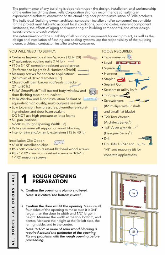
1 ROUGH OPENING PREPARATION
A. Confirm the opening is plumb and level.Note: It is critical the bottom is level.
B. Confirm the door will fit the opening. Measure all four sides of the opening to make sure it is 3/4" larger than the door in width and 1/2" larger in height. Measure the width at the top, bottom, and center. Measure the height at the far left side, the far right side, and in the center.Note: 1-1/2" or more of solid wood blocking is required around the perimeter of the opening. Fix any problems with the rough opening before proceeding.
Interior
Interior
AL
L D
OO
RS
A
LL
DO
OR
S
AL
L
YOU WILL NEED TO SUPPLY: TOOLS REQUIRED:
(Performance Upgrade & HurricaneShield)
(Minimum of 3/16’ diameter x 3")
® SmartFlash™ foil backed butyl window and door flashing tape or equivalent
equivalent high quality, multi-purpose sealant-
ing window and door foam sealant. DO NOT use high pressure or latex foams
6-5/8" x (Rough Opening Width +2)
Installation Clip Option:
1-1/2" masonry screws
and small flat blade)
(Architect Series®)
(Designer Series®)
1/8" and masonry bit for
concrete applications
1A
1B
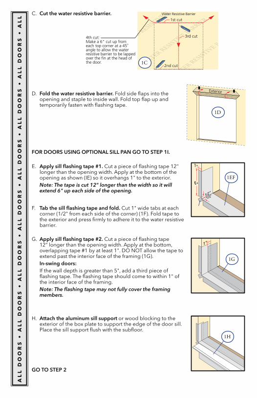
FOR DOORS USING OPTIONAL SILL PAN GO TO STEP 1I.
Exterior
4th cut: Make a 6" cut up from each top corner at a 45o angle to allow the water resistive barrier to be lapped over the fin at the head of the door.
1st cut
2nd cut
3rd cut
Water Resistive Barrier C. Cut the water resistive barrier.
D. Fold the water resistive barrier. Fold side flaps into the opening and staple to inside wall. Fold top flap up and temporarily fasten with flashing tape.
E. Apply sill flashing tape #1. Cut a piece of flashing tape 12" longer than the opening width. Apply at the bottom of the opening as shown (IE) so it overhangs 1" to the exterior.Note: The tape is cut 12" longer than the width so it will extend 6" up each side of the opening.
F. Tab the sill flashing tape and fold. Cut 1" wide tabs at each corner (1/2" from each side of the corner) (1F). Fold tape to the exterior and press firmly to adhere it to the water resistive barrier.
1"
1/2"
1/2"
6"
1" Apply sill flashing tape #2. Cut a piece of flashing tape 12" longer than the opening width. Apply at the bottom,
In-swing doors: If the wall depth is greater than 5", add a third piece of
flashing tape. The flashing tape should come to within 1" of the interior face of the framing.Note: The flashing tape may not fully cover the framing members.
H. Attach the aluminum sill support or wood blocking to the exterior of the box plate to support the edge of the door sill. Place the sill support flush with the subfloor.
GO TO STEP 2
1EF
1D
1C
1G
1H
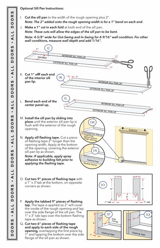
Optional Sill Pan Instructions:
I. Cut the sill pan to the width of the rough opening plus 2".Note: The 2" added onto the rough opening width is for a 1" bend on each end.
J. Make a 1" cut in each fold at both end of the sill pan.Note: These cuts will allow the edges of the sill pan to be bent.
Note: 4-5/8" wide for Out-Swing and In-Swing for 4-9/16" wall condition. For other wall conditions, measure wall depth and add 1/16".
INTERIOR SILL PAN LIP
EXTERIOR SILL PAN LIP 1"
1"
Variable1"
INTERIOR SILL PAN LIP
EXTERIOR SILL PAN LIP
1"
INTERIOR SILL PAN LIP
EXTERIOR SILL PAN LIP
Exterior EXTERIOR SILL PAN LIP Install flush against exterior rough opening.
EXTERIOR SILL PAN LIP Flashing Tape Weather Barrier
K. Cut 1" offf each end of the interior sill pan lip.
L. Bend each end of the center panel up.
M. Install the sill pan by sliding into place until the exterior sill pan lip is flush with the exterior of the rough opening.
N. Apply sill flashing tape. Cut a piece of flashing tape 2" longer than the opening width. Apply at the bottom of the opening, covering the exterior sill pan lip as shown.Note: If applicable, apply spray adhesive to building felt prior to applying the flashing tape.
O. Cut two 9" pieces of flashing tape with a 1" x 3"tab at the bottom, on opposite corners as shown.
9"
3"
1" tab
3"
2"
9"
1" tab
3"
2"
EXTERIOR SILL PAN LIP Flashing Tape
9"
1"
2" Side Flange
EXTERIOR SILL PAN LIP Flashing Tape
1"
P. Apply the tabbed 9" pieces of flashing tap. The tape is applied so 2" will cover the inside of the rough opening and lap over the side flange of the sill pan. The 1" x 3" tab laps over the bottom flashing tape as shown.
Q. Cut two 6" pieces of flashing tape and apply to each side of the rough opening, overlapping the first piece by 1" and lapping the bottom over the side flange of the sill pan as shown.
DO
OR
S �
AL
L D
OO
RS
� A
LL
DO
OR
S �
AL
L D
OO
RS
� A
LL
DO
OR
S �
AL
L D
OO
RS
� A
LL
DO
OR
S
1J
1K
1L
1M
1N
1O
1P 1Q
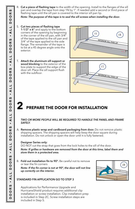
2 PREPARE THE DOOR FOR INSTALLATION
TWO OR MORE PEOPLE WILL BE REQUIRED TO HANDLE THE PANEL AND FRAME SAFELY.
A. Remove plastic wrap and cardboard packaging from door. Do not remove plastic shipping spacers. The shipping spacers will help keep the door square during installation. Do not unlock or open the door until it is fully fastened.
Designer Series only: DO NOT cut the strap that goes from the lock holes to the sill of the door.Note: If grilles or hardware are removed from the door at this time, label them and store them in a protected area.
R. Cut a piece of flashing tape to the width of the opening. Install to the flanges of the sill pan and overlap the tape from step 1N by 1". If needed add a second or third piece of flashing tape until the sill pan is covered to the interior sill pan lip.Note: The purpose of this tape is to seal the sill screws when installing the door.
S. Cut two pieces of flashing tape 1-1/2" x 6" and apply to the bottom corners of the opening by beginning in the corner of the sill pan, with 3/4" of the tape applied to the sill pan and 3/4" of the tape applied to the side flange. The remainder of the tape is to be at a 45 degree angle onto the exterior.
EXTERIOR SILL PAN LIP
INTERIOR SILL PAN LIP
1"
EXTERIOR SILL PAN LIP
INTERIOR SILL PAN LIP
T. Attach the aluminum sill support or wood blocking to the exterior of the box plate to support the edge of the door sill. Place the sill support flush with the subfloor.
B. Fold out installation fin to 90°. Be careful not to remove or tear the fin cornersNote: If the fin corner is not at 90°, the door will not line up correctly on the interior.
STANDARD FIN APPLICATION GO TO STEP 3
Applications for Performance Upgrade and HurricaneShield product requires additional clip installation or screw installation. Clip installation prep is included in Step 2C. Screw installation steps are included in Step 5.
DO
OR
S �
AL
L D
OO
RS
� A
LL
DO
OR
S �
AL
L D
OO
RS
� A
LL
DO
OR
S �
AL
L D
OO
RS
� A
LL
DO
OR
S
1S 1R
1T
2B
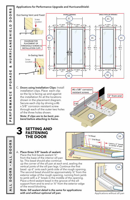
Applications for Performance Upgrade and HurricaneShield:
6" 16" MAX O.C.
16" MAX O.C.
16" MAX O.C.
16" MAX O.C.
6"
6"
6" 6"
6" 6" 6"
DOUBLE OPERABLE
6"
6"
16" MAX. O.C.
6"
6"
16" MAX. O.C.
16" MAX O.C.
16" MAX O.C.
6" 6"
6" 6"
SINGLE FIXED OR OPERABLE
6"
6"
16" MAX. O.C.
6"
6"
16" MAX. O.C.
DIAGRAM FOR PLACEMENT OF
THRESHOLD SCREWS &INSTALLATION CLIPS
C. Doors using Installation Clips: Install installation clips. Place each clip so the lip is facing up and against the installation fin at the locations shown in the placement diagram.
x 5/8" corrosion resistant screw through each of the outer two holes of the three holes shown. Note: If clips are to be bent; pre-bend before attaching to frame.
6“ from end
Lip
#6 x 5/8” corrosion resistant screws
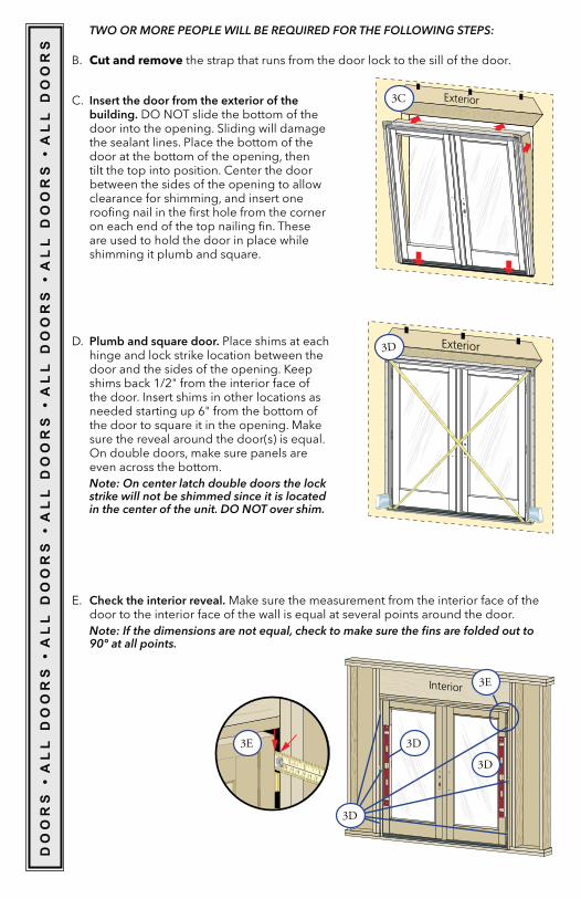
3 SETTING AND FASTENING THE DOOR
A. Place three 3/8" beads of sealant. Place the first beads sealant ½" from the base of the interior sill pan lip. This bead should also continue up the corner of the sill pan at each end, sealing the vertical joints of the sill pan legs. Continue the first bead up 6" onto each jamb side of the rough opening. The second bead should be approximately ½" from the exterior edge of the rough opening, running from jamb to jamb with a 2" break in the middle of the opening. Place a third sealant bead in the groove of the sill support from end to end or ¼" from the exterior edge of the wood blocking. Note: Sill sealant detail is the same for applications with and without optional sill pan.
12
3
6”
PE
RF
OR
MA
NC
E U
PG
RA
DE
& H
UR
RIC
AN
ES
HIE
LD
DO
OR
SA
LL
DO
OR
S �
AL
L D
OO
RS
EXTERIOR SILL PAN LIP
INTERIOR SILL PAN LIP
2nd Bead
Leave a 2" break in center of pan
1st Bead
3rd Bead
6”
Out-Swing Vent and Fixed
In-Swing Vent
Screw Location
Screw Location
Applications without sill pan
2C 2C
2C2C 2C
5E 5E
2C
3A
3A
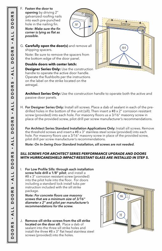
TWO OR MORE PEOPLE WILL BE REQUIRED FOR THE FOLLOWING STEPS:
B. Cut and remove the strap that runs from the door lock to the sill of the door.
C. Insert the door from the exterior of the building. DO NOT slide the bottom of the door into the opening. Sliding will damage the sealant lines. Place the bottom of the door at the bottom of the opening, then tilt the top into position. Center the door between the sides of the opening to allow clearance for shimming, and insert one roofing nail in the first hole from the corner on each end of the top nailing fin. These are used to hold the door in place while shimming it plumb and square.
D. Plumb and square door. Place shims at each hinge and lock strike location between the door and the sides of the opening. Keep shims back 1/2" from the interior face of the door. Insert shims in other locations as needed starting up 6" from the bottom of the door to square it in the opening. Make sure the reveal around the door(s) is equal. On double doors, make sure panels are even across the bottom.Note: On center latch double doors the lock strike will not be shimmed since it is located in the center of the unit. DO NOT over shim.
Interior
1 2 0 3 0 4 0 5 0 6 0 7 0
2 3
INCHES mm
Exterior
Exterior
E. Check the interior reveal. Make sure the measurement from the interior face of the door to the interior face of the wall is equal at several points around the door.Note: If the dimensions are not equal, check to make sure the fins are folded out to 90° at all points.
DO
OR
S �
AL
L D
OO
RS
� A
LL
DO
OR
S �
AL
L D
OO
RS
� A
LL
DO
OR
S �
AL
L D
OO
RS
� A
LL
DO
OR
S
3C
3D
3E
3D
3D
3D
3E
F. Fasten the door to opening by driving 2"
into each pre-punched hole in the nailing fin.Note: Make sure the fin corner is lying as flat as possible.
Exterior
Interior
Carefully open the door(s) and remove all shipping spacers.Note: Be sure to remove the spacers from the bottom edge of the door panel.
Double doors with center latch: Designer Series Only: Use the construction
handle to operate the active door handle. Operate the flushbolts per the instructions on the label on the strike located on the astragal.
Architect Series Only: Use the construction handle to operate both the active and passive door panels.
H. For Designer Series Only: Install sill screws. Place a dab of sealant in each of the pre-
screw (provided) into each hole. For masonry floors us a 3/16" masonry screw in place of the provided screw, pilot drill per screw manufacturer’s recommendations.
For Architect Series Standard Installation Applications Only: Install sill screws. Remove
hole. For masonry floors use a 3/16" masonry screw in place of the provided screw, pilot drill per screw manufacturer’s recommendations.
SILL SCREWS FOR ARCHITECT SERIES PERFORMANCE UPGRADE AND DOORS WITH HURRICANESHIELD IMPACT-RESISTANT GLASS ARE INSTALLED IN STEP 5.
I. For Low Profile Sills: through each installation screw hole drill a 1/8" pilot; and install a
into the pilot hole into the floor. For doors including a standard lock install tubs per instruction included with the sill strike package. Note: For concrete floors use masonry screws that are a minimum size of 3/16" diameter x 2" and pilot per manufacturer’s recommendations for the screw.
J. Remove sill strike screws from the sill strike located on the door sill. Place a dab of sealant into the three sill strike holes and
screws (provided) into the holes.
DO
OR
S �
AL
L D
OO
RS
� A
LL
DO
OR
S �
AL
L D
OO
RS
� A
LL
DO
OR
S �
AL
L D
OO
RS
� A
LL
DO
OR
S
Note: On In-Swing Door Standard Installation, sill screws are not needed.
3H
3K
3J
3F
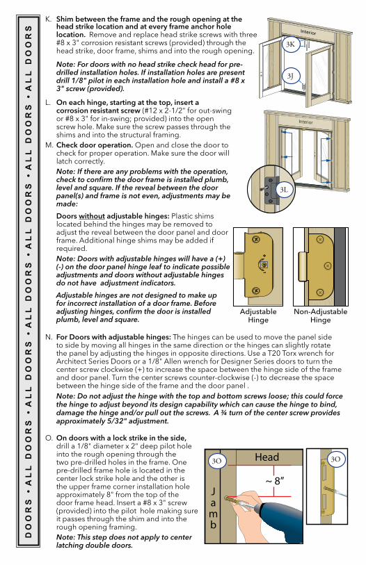
K. Shim between the frame and the rough opening at the head strike location and at every frame anchor hole location. Remove and replace head strike screws with three
head strike, door frame, shims and into the rough opening.
L. On each hinge, starting at the top, insert a corrosion resistant screw
screw hole. Make sure the screw passes through the shims and into the structural framing.
M. Check door operation. Open and close the door to check for proper operation. Make sure the door will latch correctly.Note: If there are any problems with the operation, check to confirm the door frame is installed plumb, level and square. If the reveal between the door panel(s) and frame is not even, adjustments may be made:
Doors without adjustable hinges: Plastic shims located behind the hinges may be removed to adjust the reveal between the door panel and door frame. Additional hinge shims may be added if required.Note: Doors with adjustable hinges will have a (+)(-) on the door panel hinge leaf to indicate possible adjustments and doors without adjustable hinges do not have adjustment indicators.
Adjustable hinges are not designed to make up for incorrect installation of a door frame. Before adjusting hinges, confirm the door is installed plumb, level and square.
Adjustable Hinge
Non-Adjustable Hinge
N. For Doors with adjustable hinges: The hinges can be used to move the panel side to side by moving all hinges in the same direction or the hinges can slightly rotate
Architect Series Doors or a 1/8" Allen wrench for Designer Series doors to turn the center screw clockwise (+) to increase the space between the hinge side of the frame and door panel. Turn the center screws counter-clockwise (-) to decrease the space between the hinge side of the frame and the door panel .Note: Do not adjust the hinge with the top and bottom screws loose; this could force the hinge to adjust beyond its design capability which can cause the hinge to bind, damage the hinge and/or pull out the screws. A ¾ turn of the center screw provides approximately 5/32" adjustment.
O. On doors with a lock strike in the side, drill a 1/8" diameter x 2" deep pilot hole into the rough opening through the two pre-drilled holes in the frame. One pre-drilled frame hole is located in the center lock strike hole and the other is the upper frame corner installation hole approximately 8" from the top of the
(provided) into the pilot hole making sure it passes through the shim and into the rough opening framing. Note: This step does not apply to center latching double doors.
DO
OR
S �
AL
L D
OO
RS
� A
LL
DO
OR
S �
AL
L D
OO
RS
� A
LL
DO
OR
S �
AL
L D
OO
RS
� A
LL
DO
OR
S
Note: For doors with no head strike check head for pre-drilled installation holes. If installation holes are present drill 1/8" pilot in each installation hole and install a #8 x 3" screw (provided).
Interior
Interior
Head
~ 8”Jamb
3K
3J
3L
3O 3O
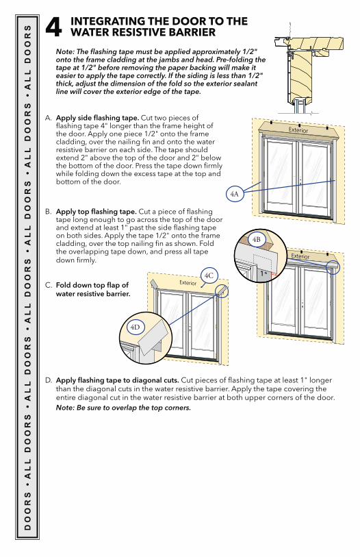
4 INTEGRATING THE DOOR TO THE WATER RESISTIVE BARRIER
A. Apply side flashing tape. Cut two pieces of flashing tape 4" longer than the frame height of the door. Apply one piece 1/2" onto the frame cladding, over the nailing fin and onto the water resistive barrier on each side. The tape should extend 2" above the top of the door and 2" below the bottom of the door. Press the tape down firmly while folding down the excess tape at the top and bottom of the door.
Note: The flashing tape must be applied approximately 1/2" onto the frame cladding at the jambs and head. Pre-folding the tape at 1/2" before removing the paper backing will make it easier to apply the tape correctly. If the siding is less than 1/2" thick, adjust the dimension of the fold so the exterior sealant line will cover the exterior edge of the tape.
Exterior
B. Apply top flashing tape. Cut a piece of flashing tape long enough to go across the top of the door and extend at least 1" past the side flashing tape on both sides. Apply the tape 1/2" onto the frame cladding, over the top nailing fin as shown. Fold the overlapping tape down, and press all tape down firmly.
Exterior
1" C. Fold down top flap of
water resistive barrier.
D. Apply flashing tape to diagonal cuts. Cut pieces of flashing tape at least 1" longer than the diagonal cuts in the water resistive barrier. Apply the tape covering the entire diagonal cut in the water resistive barrier at both upper corners of the door.Note: Be sure to overlap the top corners.
Exterior
DO
OR
S �
AL
L D
OO
RS
� A
LL
DO
OR
S �
AL
L D
OO
RS
� A
LL
DO
OR
S �
AL
L D
OO
RS
� A
LL
DO
OR
S
4A
4B
4C
4D
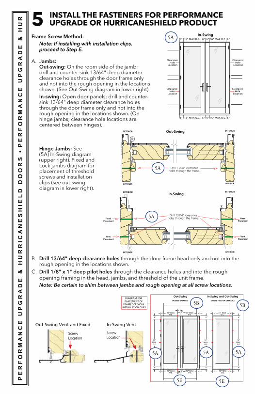
5 INSTALL THE FASTENERS FOR PERFORMANCE UPGRADE OR HURRICANESHIELD PRODUCT
Frame Screw Method:Note: If installing with installation clips, proceed to Step E.
A. Jambs: Out-swing: On the room side of the jamb; drill and counter-sink 13/64" deep diameter clearance holes through the door frame only and not into the rough opening in the locations shown. (See Out-Swing diagram in lower right).
In-swing: Open door panels; drill and counter-sink 13/64" deep diameter clearance holes through the door frame only and not into the rough opening in the locations shown. (On hinge jambs; clearance hole locations are centered between hinges).
PE
RF
OR
MA
NC
E U
PG
RA
DE
& H
UR
RIC
AN
ES
HIE
LD
DO
OR
S �
��PE
RF
OR
MA
NC
E U
PG
RA
DE
& H
UR
EXTERIOR
INTERIOR
Drill 13/64" clearanceholes through the frame.
Out-Swing
In-Swing
EXTERIOR
INTERIOR
EXTERIOR
INTERIOR
EXTERIOR
INTERIOR
Drill 13/64" clearanceholes through the frame.
Vent Placement
Fixed Placement
Vent Placement
Fixed Placement
6" 16" MAX O.C.16" MAX O.C. 6"6" 6"
6" 16" MAX O.C.16" MAX O.C. 6"6" 6"
In-Swing
Clearance Hole
Location
Clearance Hole
Location
Clearance Hole
Location
Clearance Hole
Location
6" 16" MAX O.C.
16" MAX O.C.
16" MAX O.C.
16" MAX O.C.
6"
6"
6" 6"
6" 6" 6"
DOUBLE OPERABLE
6"
6"
16" MAX. O.C.
6"
6"
16" MAX. O.C.
16" MAX O.C.
16" MAX O.C.
6" 6"
6" 6"
SINGLE FIXED OR OPERABLE
6"
6"
16"MAX. O.C.
DIAGRAM FOR PLACEMENT OF
FRAME SCREWS & INSTALLATION CLIPS
Out-Swing In-Swing and Out-Swing
Out-Swing Vent and Fixed
Screw Location
In-Swing Vent
Screw Location
Hinge Jambs: See (5A) In-Swing diagram (upper right). Fixed and Lock jambs diagram for placement of threshold screws and installation clips (see out-swing diagram in lower right).
B. Drill 13/64" deep clearance holes through the door frame head only and not into the rough opening in the locations shown.
C. Drill 1/8" x 1" deep pilot holes through the clearance holes and into the rough opening framing in the head, jambs, and threshold of the unit frame.Note: Be certain to shim between jambs and rough opening at all screw locations.
5A
5A
5A
5B 5B
5A5A5A
5E 5E
EXTERIOR
INTERIOR
Drill 1/8” diameter pilotholes through the clearance
hole in the frame.
Out-Swing
#10 x 3-1/2" corrosion resistant wood screw
EXTERIOR
INTERIOR
SILL
HEAD
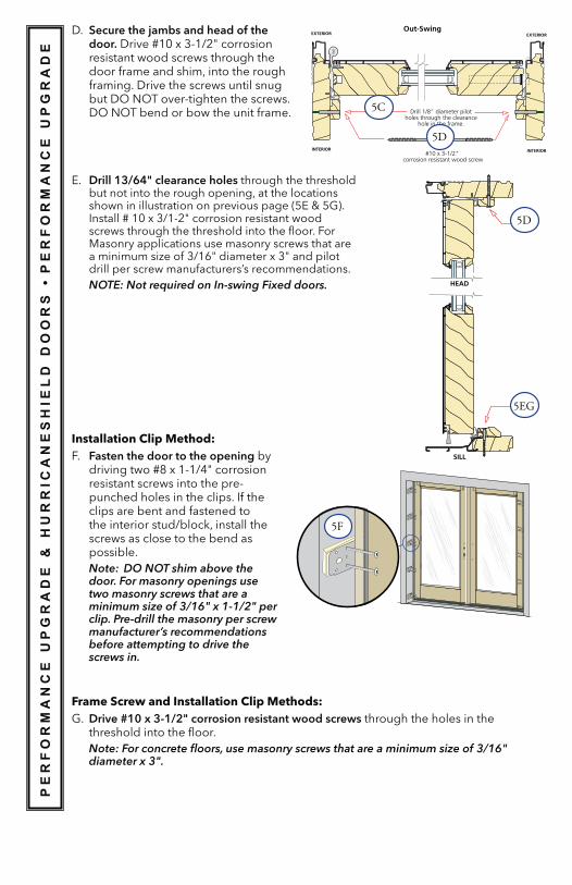
D. Secure the jambs and head of the door.resistant wood screws through the door frame and shim, into the rough framing. Drive the screws until snug but DO NOT over-tighten the screws. DO NOT bend or bow the unit frame.
E. Drill 13/64" clearance holes through the threshold but not into the rough opening, at the locations
screws through the threshold into the floor. For Masonry applications use masonry screws that are
drill per screw manufacturers’s recommendations.NOTE: Not required on In-swing Fixed doors.
Installation Clip Method:F. Fasten the door to the opening by
resistant screws into the pre-punched holes in the clips. If the clips are bent and fastened to the interior stud/block, install the screws as close to the bend as possible.Note: DO NOT shim above the door. For masonry openings use two masonry screws that are a minimum size of 3/16" x 1-1/2" per clip. Pre-drill the masonry per screw manufacturer’s recommendations before attempting to drive the screws in.
PE
RF
OR
MA
NC
E U
PG
RA
DE
& H
UR
RIC
AN
ES
HIE
LD
DO
OR
S �
��PE
RF
OR
MA
NC
E U
PG
RA
DE
Frame Screw and Installation Clip Methods: Drive #10 x 3-1/2" corrosion resistant wood screws through the holes in the threshold into the floor.Note: For concrete floors, use masonry screws that are a minimum size of 3/16" diameter x 3".
5C
5D
5D
5EG
5F
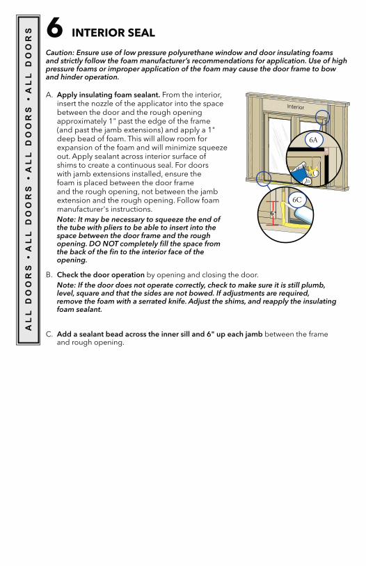
6 INTERIOR SEAL
A. Apply insulating foam sealant. From the interior,
between the door and the rough opening approximately 1" past the edge of the frame (and past the jamb extensions) and apply a 1" deep bead of foam. This will allow room for
out. Apply sealant across interior surface of shims to create a continuous seal. For doors with jamb extensions installed, ensure the foam is placed between the door frame and the rough opening, not between the jamb extension and the rough opening. Follow foam manufacturer's instructions.Note: It may be necessary to squeeze the end of the tube with pliers to be able to insert into the space between the door frame and the rough opening. DO NOT completely fill the space from the back of the fin to the interior face of the opening.
Caution: Ensure use of low pressure polyurethane window and door insulating foams and strictly follow the foam manufacturer’s recommendations for application. Use of high pressure foams or improper application of the foam may cause the door frame to bow and hinder operation.
Interior
6"
B. Check the door operation by opening and closing the door.Note: If the door does not operate correctly, check to make sure it is still plumb, level, square and that the sides are not bowed. If adjustments are required, remove the foam with a serrated knife. Adjust the shims, and reapply the insulating foam sealant.
C. Add a sealant bead across the inner sill and 6" up each jamb between the frame and rough opening.
AL
L D
OO
RS
� A
LL
DO
OR
S �
AL
L D
OO
RS
� A
LL
DO
OR
S
6A
6C
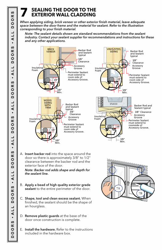
7 SEALING THE DOOR TO THE EXTERIOR WALL CLADDING
When applying siding, brick veneer or other exterior finish material, leave adequate space between the door frame and the material for sealant. Refer to the illustration corresponding to your finish material.
Note: The sealant details shown are standard recommendations from the sealant industry. Contact your sealant supplier for recommendations and instructions for these and any other applications.
BRICK VENEER
3/8" Clearance
Backer Rod and Sealant typical
Insulating Foam
Perimeter Sealant must extend to room side of Accessory Groove.
Accessory Groove
3/8" Min.
3/8"
3/8" Min.
3/8"
VINYL/STEEL SIDING
3/8" Clearance
Backer Rod and Sealant typical
Insulating Foam
Perimeter Sealant must extend to room side of Accessory Groove.
Accessory Groove
STUCCO
3/8" Clearance
Backer Rod and Sealant typical
Perimeter Sealant must extend to roomside of Accessory Groove.
Accessory Groove Insulating
Foam
3/8" Min.
3/8"
Insulating Foam
Perimeter Sealant must extend to room side of Accessory Groove.
WOOD SIDING WITH TRIM
3/8" Clearance
Accessory Groove
Backer Rod and Sealant typical
3/8" Min.
3/8"
A. Insert backer rod into the space around the door so there is approximately 3/8" to 1/2" clearance between the backer rod and the exterior face of the door.Note: Backer rod adds shape and depth for the sealant line.
B. Apply a bead of high quality exterior grade sealant to the entire perimeter of the door.
C. Shape, tool and clean excess sealant. When finished, the sealant should be the shape of an hourglass.
D. Remove plastic guards at the base of the door once construction is complete.
E. Install the hardware. Refer to the instructions included in the hardware box.
DO
OR
S �
AL
L D
OO
RS
� A
LL
DO
OR
S �
AL
L D
OO
RS
� A
LL
DO
OR
S �
AL
L D
OO
RS
� A
LL
DO
OR
S
7A7B
INTERIOR FINISHINGIf products cannot be finished immediately, cover with clear plastic to protect from dirt, damage and moisture. Remove any construction residue before finishing. Sand all wood
Pella products must be finished per the below instructions; failure to follow these instructions voids the Limited Warranty.
sash edges.
Note: To maintain proper product performance do not paint, finish or remove the weather-stripping, mohair dust pads, gaskets or vinyl parts. Air and water leakage will result if these parts are removed. After finishing, allow venting windows and doors to dry completely before closing them.Pella Corporation is not responsible for interior paint and stain finish imperfections for any product that is not factory-applied by Pella Corporation. Use of inappropriate finishes, solvents, brickwash, or cleaning chemicals will cause adverse reactions with window and door materials and voids Limited Warranty.For additional information on finishing see the Pella Owner’s Manual or go to www.pella.com.
EXTERIOR FINISHINGThe exterior frame and sash are protected by aluminum cladding with a Pella EnduraClad® or EnduraClad Plus baked-on factory finish that needs no painting. Clean this surface with mild soap and water. Stubborn stains and deposits may be removed with mineral spirits. DO NOT use abrasives. DO NOT scrape or use tools that might damage the surface.Use of inappropriate finishes, solvents, brickwash or cleaning chemicals will cause adverse reactions with window and door materials and voids the Limited Warranty.
CARE AND MAINTENANCECare and maintenance information is available in the Pella Owner’s Manual. You can obtain an owner’s manual by contacting your local Pella retailer. This information is also available at www.pella.com.
Because all construction must anticipate some water infiltration, it is important that the wall system be designed and constructed to properly manage moisture. Pella Corporation is not responsible for claims or damages caused by anticipated and unanticipated water infiltration; deficiencies in building design, construction and maintenance; failure to install Pella® products in accordance with Pella installation instructions; or the use of Pella products in wall systems which do not allow for proper management of moisture within the wall systems. The determination of the suitability of all building components, including the use of Pella products, as well as the design and installation of flashing and sealing systems are the responsibility of the Buyer or User, the architect, contractor, installer, or other construction professional and are not the responsibility of Pella.Pella products should not be used in barrier wall systems which do not allow for proper management of moisture within the wall systems, such as barrier Exterior Insulation and Finish Systems, (EIFS) (also known as synthetic stucco) or other non-water managed
Colorado, Pella makes no warranty of any kind and assumes no responsibility for Pella windows and doors installed in barrier wall systems. In the states listed above, the installation of Pella products in barrier wall or similar systems must be in accordance with Pella installation instructions.Product modifications that are not approved by Pella Corporation will void the Limited Warranty.
IMPORTANT NOTICE
DO
OR
S �
AL
L D
OO
RS
� A
LL
DO
OR
S �
AL
L D
OO
RS
� A
LL
DO
OR
S �
AL
L D
OO
RS
� A
LL
DO
OR
S
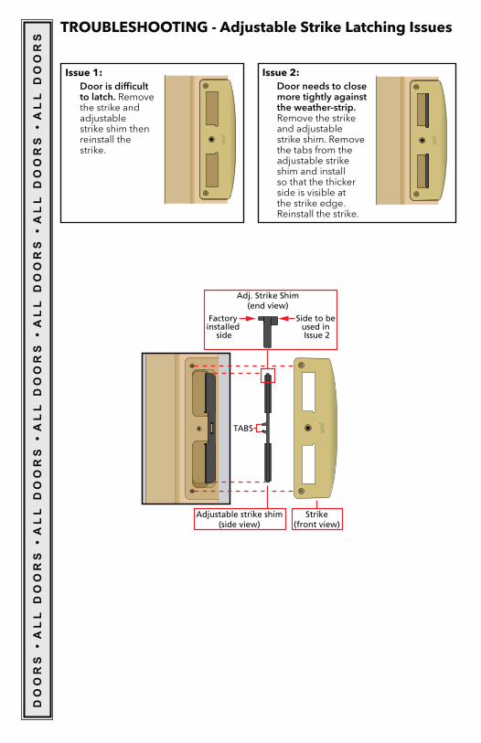
TROUBLESHOOTING - Adjustable Strike Latching Issues
Issue 2: Door needs to close
more tightly against the weather-strip. Remove the strike and adjustable strike shim. Remove the tabs from the adjustable strike shim and install so that the thicker side is visible at the strike edge. Reinstall the strike.
Issue 1: Door is difficult
to latch. Remove the strike and adjustable strike shim then reinstall the strike.
DO
OR
S �
AL
L D
OO
RS
� A
LL
DO
OR
S �
AL
L D
OO
RS
� A
LL
DO
OR
S �
AL
L D
OO
RS
� A
LL
DO
OR
S