Embed Size (px)
Citation preview
1Radiant Floor Installation Handbook
Read the entire contents of this handbook before installing a WirsboRadiant Floor/Ceiling Heating System or RADIPEX™ Baseboard Sup-ply System. Refer to this handbook, as necessary, during all phasesof installation.
Installation HandbookRadiant Floor
Radiant CeilingRADIPEX™ Baseboard andRadiator Supply Systems
Wirsbo Installation Handbook for Radiant Floor, Radiant Ceiling,RADIPEX™ Baseboard and Radiator Supply Systems is published byWirsbo Company, 5925 148th Street West, Apple Valley, MN 55124,612-891-2000.
© 1999 Wirsbo Company. All rights reserved.
Printed in the United States of America.First Printing - April 1994Second Printing - April 1995Third Printing - May 1996Fourth Printing - October 1997Fifth Printing - April 1998Sixth Printing - August 1999
6th Edition
2 Radiant Floor Installation Handbook
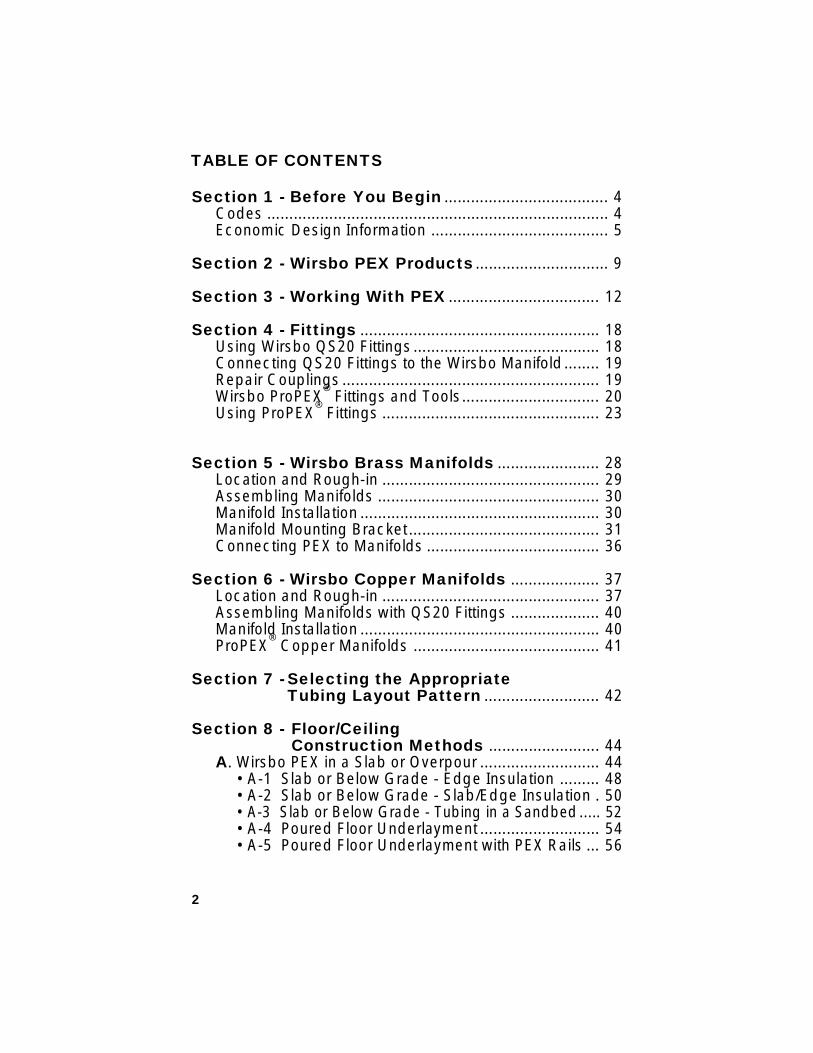
Section 1 - Before You Begin ..................................... 4Codes ............................................................................. 4Economic Design Information ........................................ 5
Section 2 - Wirsbo PEX Products .............................. 9
Section 3 - Working With PEX .................................. 12
Section 4 - Fittings ...................................................... 18Using Wirsbo QS20 Fittings .......................................... 18Connecting QS20 Fittings to the Wirsbo Manifold........ 19Repair Couplings .......................................................... 19Wirsbo ProPEX
® Fittings and Tools............................... 20
Using ProPEX® Fittings ................................................. 23
Section 5 - Wirsbo Brass Manifolds ....................... 28Location and Rough-in ................................................. 29Assembling Manifolds .................................................. 30Manifold Installation ...................................................... 30Manifold Mounting Bracket........................................... 31Connecting PEX to Manifolds ....................................... 36
Section 6 - Wirsbo Copper Manifolds .................... 37Location and Rough-in ................................................. 37Assembling Manifolds with QS20 Fittings .................... 40Manifold Installation ...................................................... 40ProPEX
® Copper Manifolds .......................................... 41
Section 7 - Selecting the AppropriateTubing Layout Pattern .......................... 42
Section 8 - Floor/CeilingConstruction Methods ......................... 44
A. Wirsbo PEX in a Slab or Overpour ........................... 44• A-1 Slab or Below Grade - Edge Insulation ......... 48• A-2 Slab or Below Grade - Slab/Edge Insulation . 50• A-3 Slab or Below Grade - Tubing in a Sandbed..... 52• A-4 Poured Floor Underlayment ........................... 54• A-5 Poured Floor Underlayment with PEX Rails ... 56
TABLE OF CONTENTS
3Radiant Floor Installation Handbook
TABLE OF CONTENTS
B. Wirsbo PEX™ in Suspended Wood Floors ................. 58• B-1 Under a Suspended Wood Floor
(Emission Plates) .................................................. 60• B-2 Under a Suspended Wood Floor
(Joist Hangars) ..................................................... 62• B-3 Under a Suspended Wood Floor
(Wirsbo PEX Clips) ................................................ 64• B-4 Under a Suspended Wood Floor
(Staple Gun Kits) ................................................... 66• Sandwich Method ................................................. 68• Radiant Ceiling...................................................... 70
(Emission Plates)• Avoiding Noise in Aluminum Plate Installations .... 72
Section 9 - System Start-up ..................................... 74Pressure Testing the System ........................................ 74Filling the System with Water ........................................ 74Purging Air from the System ......................................... 75Initial Balancing of Manifold Loops .............................. 76Fine Balancing of Manifold Loops ................................ 77
Section 10 - Electrical Controls .............................. 78Schematic #1 Wiring Diagram ofDT10 / Zone Control Module / Relay ............................ 81Schematic #2 Wiring Diagram for
DT10 / Four Wire MVA / Relay ............. 82Schematic #3 Wiring Diagram for multiple
DT10 / Four Wire MVA / Relay ............. 83Schematic #4 Wiring Diagram for
DT10 / Relay ........................................ 84Schematic #5 Wiring Diagram for T86H / Four Wire
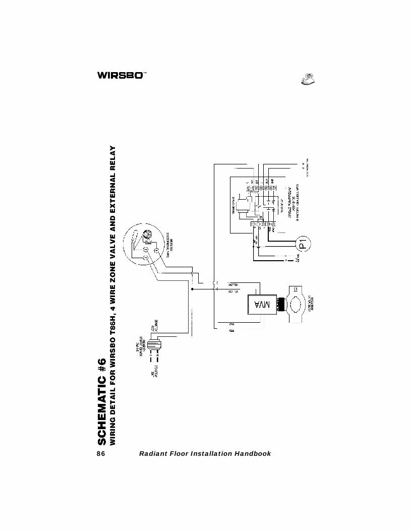
MVA / Relay ......................................... 85Schematic #6 Wiring Diagram for T86H / Four Wire
Zone Valve / Relay............................... 86
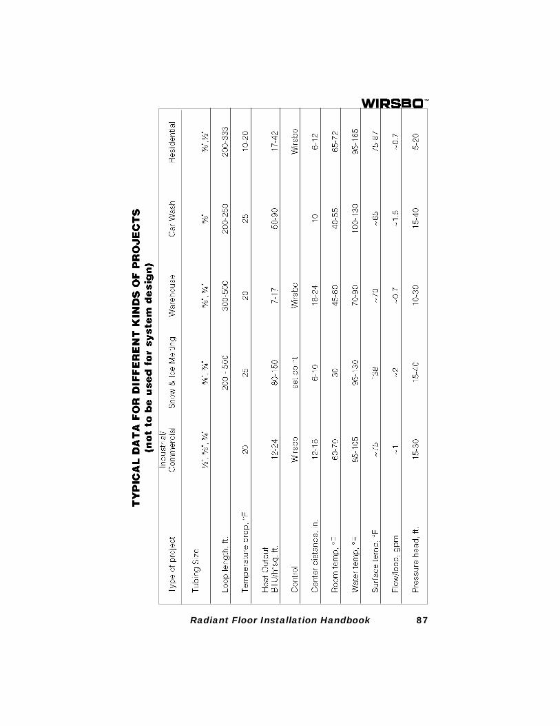
Project Data Chart ....................................................... 87
RADIPEX™ System Installation ............................... 88
4 Radiant Floor Installation Handbook
SECTION 1: BEFORE YOU BEGIN
The purpose of this handbook is to familiarize contractors, archi-tects, engineers and HVAC officials with Wirsbo Company’srecommended methods of constructing and installing WirsboRadiant Floor/Ceiling Heating Systems and RADIPEX™ Systems.
CodesWirsbo systems should be installed by a hydronic heating instal-lation technician after carefully reviewing all applicable building,heating and mechanical codes. Any conflicts with the codes mustbe resolved before installation.
Wirsbo PEX tubing products are manufactured to ASTM F876 -Standard Specification for Cross-Linked Polyethylene (PEX)Tubing. The tubing is listed to ASTM F876 and the tubing andfitting system is listed to ASTM F877 and ASTM F1960 by a thirdparty independent testing laboratory.
BOCA - The use of ASTM F876 and ASTM F877 PEX tubing islisted for use in the BOCA NATIONAL MECHANICAL CODEunder Hydronic Pipe - Section M-703.0 (93).
ICBO - Wirsbo PEX tubing products and radiant panel heatingproducts are approved for use by ICBO. See ICBO Report No.4407 for allowable values and/or conditions of use concerningmaterial presented in this document. ICBO reports are subject tore-examination, revision and possible cancellation.
IMC - The use of ASTM F876 and ASTM F877 PEX tubing isapproved for use in the International Mechanical Code underHydronic Piping - Section 1202.
New York State - Wirsbo PEX tubing products meet the require-ments for the New York State Uniform Fire Prevention and Build-ing Code, and are approved for use in the State of New York forsealed central heating systems including radiant floor.
5Radiant Floor Installation Handbook
Economic Design InformationIn the residential market there is a common misconception thatradiant floor heating is only for high-end, custom homes. Thissimply is not true. Like any heating system, radiant floor systemscan be designed to fit a wide array of applications and budgets.Wirsbo systems can be designed to be competitive with anyheating alternative. Wirsbo systems can be ultra-basic or ultra-sophisticated, depending on the specific requirements of anapplication and the budget of a project.
There are many ways to achieve economic design. Here aresome options:
Use The Correct PEX Product: If ferrous components (e.g.,cast iron boiler and/or circulators) are used in the system, thenWirsbo hePEX™plus with an oxygen diffusion barrier must beused. However, if there are no ferrous components in the system,the Wirsbo AQUAPEX® non-barrier tubing may be used.AQUAPEX® is the same quality tubing, but because it has nobarrier, it costs less.
Use The Proper Size Tubing: In nearly all residential appli-cations, ¹⁄₂" hePEX™plus or AQUAPEX® tubing is perfectly ad-equate. The ⁵⁄₈" tubing may also be used, but it is more costly.There are lots of advantages to ¹⁄₂" tubing besides cost. It is moreflexible and easier to work with, making it easier and faster toinstall. The only advantage to using ⁵⁄₈" tubing over ¹⁄₂" tubing is alower pressure loss over the same loop length. Larger diameterPEX WILL NOT deliver more heat per square foot of radiantpanel.
Use ³⁄₈" PEX Tubing For Joist Heating: In joist applica-tions, ³⁄₈" tubing may be used. It is even more flexible and easierto work with than ¹⁄₂" tubing. However, because of the smallerdiameter the pressure drop is significantly higher with ³⁄₈" tubingthan with ¹⁄₂" tubing, so maximum loop lengths will be shorter.Even so, 250 to 300 foot loop lengths can be done with ³⁄₈" PEX.
6 Radiant Floor Installation Handbook
Use Common Sense Control Strategies: There are manylevels of control strategies that can be used with radiant floorheating systems, ranging from simple on/off control to weatherresponsive reset packages. The higher the level of control so-phistication, the higher the upfront cost. Keep in mind, however,that these costs are often offset by greater comfort and fueleconomy.
A designer should carefully weigh the design options available,and choose the option that best fits an individual application. Forinstance, a small one or two room job will perform just fine with asimple tempering valve (if necessary) and an on/off control. Infact, a tempering valve and intermittent control will be satisfac-tory in many larger applications as well. More elaborate resetcontrols are becoming affordable and may be used in appropri-ate jobs without busting the budget.
Use Common Sense Zoning Strategies: One of the greatbenefits of radiant floor heating is to provide complete room-by-room zoning with thermostats in every room. While this adds ahigh level of control, it can also add extra cost. Often, severalrooms of similar design, use patterns, and proximity may bezoned together into a single zone without sacrificing comfort orefficiency. Zone valves or circulators used to zone a singlemanifold, rather than multiple telestats on a single manifold, canbe used to help reduce cost.
Do Not Install Any Tubing In Zero Heat Loss Areas: Ifthe heat loss of a given area is zero, do not install tubing. Anexample of this is a small room that is surrounded by heatedspace. It may very well have a zero heat loss and therefore wouldnot need additional tubing installed. The exception to this wouldbe any slab on or below grade application where downward heatloss exists.
Use Radiant Ceiling: Radiant ceiling can be used costeffectively in many situations. Radiant ceiling applications typi-cally use less tubing and fewer components than radiant floor
7Radiant Floor Installation Handbook
applications. In addition, the cost of underlayment is saved.Radiant ceiling is perfect for retrofit and remodeling applications,supplemental heat situations, and it can be used cost effectivelyin the specified housing market.
Install Tubing Between The Joists Without Plates:This application is used both in retrofit/remodel and new con-struction. Simply install the tubing in between the floor joists,either clipped or stapled to the subfloor, without aluminum heatemission plates. This is much less expensive than installationsusing plates. The only sacrifices are a higher required watertemperature and a slightly slower response time. This methodcan also be more cost effective than a poured floor underlaymentapplication. More tubing is used but the cost of the underlaymentis saved.
Use the Most Cost Effective Heat Plant: Because of itslow water temperature requirements, radiant floor and radiantceiling systems can often use water heaters as heat sources.There are limitations in terms of output and water temperature, ofcourse, but water heaters are less expensive than boilers and donot require a tempering device to achieve proper supply watertemperature. Consult your local codes before installing a waterheater as a heat source.
Use A Wirsbo Stapler: Wirsbo staplers greatly reduce instal-lation time for suspended floor applications, both above andbelow the subfloor, as well as for radiant ceiling installations. Theinvestment in the tool can be recovered after just a few jobs.
Parts Inspection: Before beginning the installation, check to besure that you have received all of the necessary componentsrequired to complete the project. Verify that all components are ingood working order and were not damaged during shipping. Reportdamaged or missing goods to your distributor or dealer as soon aspossible to avoid unnecessary delays.
8 Radiant Floor Installation Handbook
NOTE: The installation of a radiant floor heating system is apermanent fixture of the structure. Improper installation,exceeding limitations and practical expectations of the radiantfloor will be difficult, if not impossible, to correct once theinstallation is complete. Therefore, it is strongly recommendedthat a room-by-room heat loss of the structure is completedprior to installation. Wirsbo offers Radiant Express, a PCcompatible program designed specifically for radiant floor/ceiling heating applications. In addition, Wirsbo offers theComplete Design Assistance Manual (CDAM) which providesdetailed information about products, design, applications andcontrols. Contact your local sales representative for availability.
9Radiant Floor Installation Handbook
SECTION 2: WIRSBO PEX PRODUCTS
The term PEX refers to cross-linked polyethylene. Wirsbo offerstwo PEX products for radiant floor heating systems: AQUAPEX®
and Wirsbo hePEX™plus. They are similar in that they are bothcross-linked polyethylene produced by the Engel method buteach has special features that make it more suitable for specificinstallations. In this handbook the term PEX or Wirsbo PEX isgeneric and refers to both tubing products.
AQUAPEX®
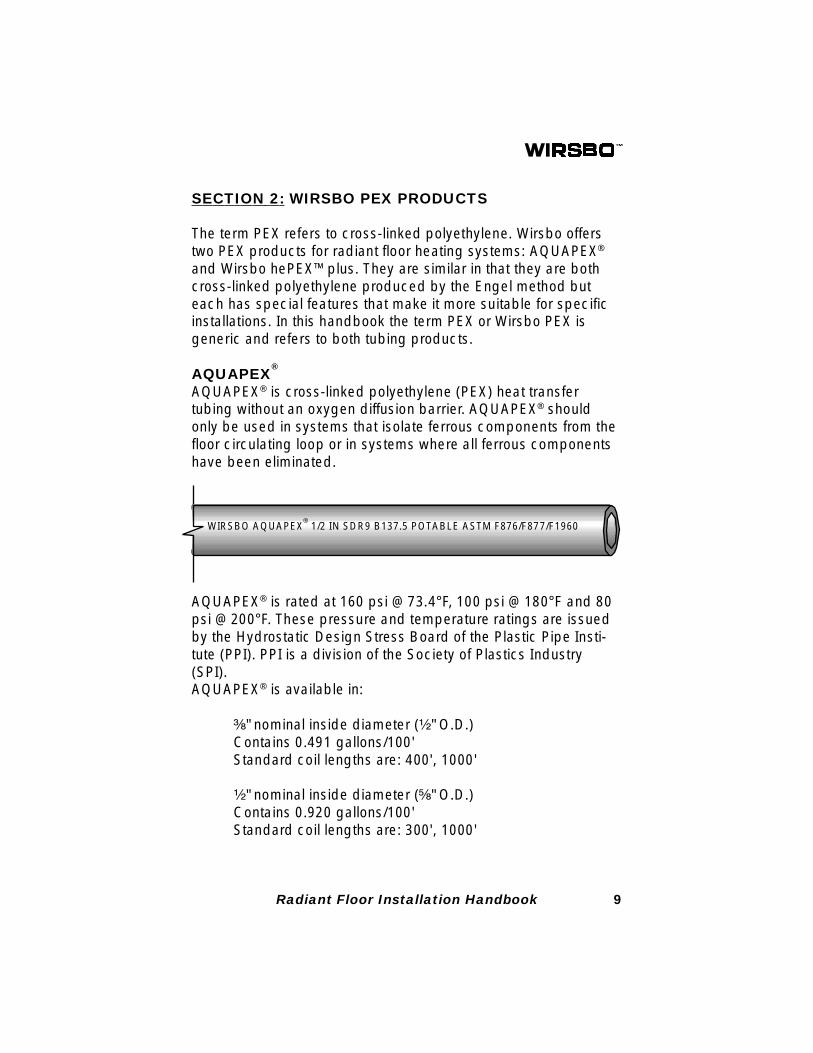
AQUAPEX® is cross-linked polyethylene (PEX) heat transfertubing without an oxygen diffusion barrier. AQUAPEX® shouldonly be used in systems that isolate ferrous components from thefloor circulating loop or in systems where all ferrous componentshave been eliminated.
WIRSBO AQUAPEX® 1/2 IN SDR9 B137.5 POTABLE ASTM F876/F877/F1960
AQUAPEX® is rated at 160 psi @ 73.4°F, 100 psi @ 180°F and 80psi @ 200°F. These pressure and temperature ratings are issuedby the Hydrostatic Design Stress Board of the Plastic Pipe Insti-tute (PPI). PPI is a division of the Society of Plastics Industry(SPI).AQUAPEX® is available in:
³⁄₈" nominal inside diameter (¹⁄₂" O.D.)Contains 0.491 gallons/100'Standard coil lengths are: 400', 1000'
¹⁄₂" nominal inside diameter (⁵⁄₈" O.D.)Contains 0.920 gallons/100'Standard coil lengths are: 300', 1000'
10 Radiant Floor Installation Handbook
⁵⁄₈" nominal inside diameter (³⁄₄" O.D.)Contains 1.387 gallons/100'Standard coil lengths are: 300', 1000'
³⁄₄" nominal inside diameter (⁷⁄₈" O.D.)Contains 1.89 gallons/100'Standard coil lengths are: 300', 500'
1" nominal inside diameter (1¹⁄₈" O.D.)Contains 3.01 gallons/100'Standard coil lengths are: 300', 500'
1¹⁄₄" nominal inside diameter (1³⁄₈" O.D.)Contains 4.65 gallons/100'Standard coil lengths are: 100'
1¹⁄₂" nominal inside diameter (1⁵⁄₈" O.D.)Contains 6.49 gallons/100'Standard coil lengths are: 100'
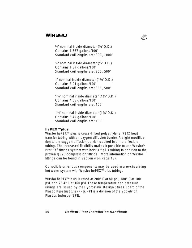
hePEX™plusWirsbo hePEX™plus is cross-linked polyethylene (PEX) heattransfer tubing with an oxygen diffusion barrier. A slight modifica-tion to the oxygen diffusion barrier resulted in a more flexibletubing. The increased flexibility makes it possible to use Wirsbo'sProPEX® fittings system with hePEX™plus tubing in addition to theproven QS20 compression fittings. (More information on Wirsbofittings can be found in Section 4 on Page 18).
Corrodible or ferrous components may be used in a re-circulatinghot water system with Wirsbo hePEX™plus tubing.
Wirsbo hePEX™plus is rated at 200° F at 80 psi, 180° F at 100psi, and 73.4° F at 160 psi. These temperature and pressureratings are issued by the Hydrostatic Design Stress Board of thePlastic Pipe Institute (PPI). PPI is a division of the Society ofPlastics Industry (SPI).
11Radiant Floor Installation Handbook
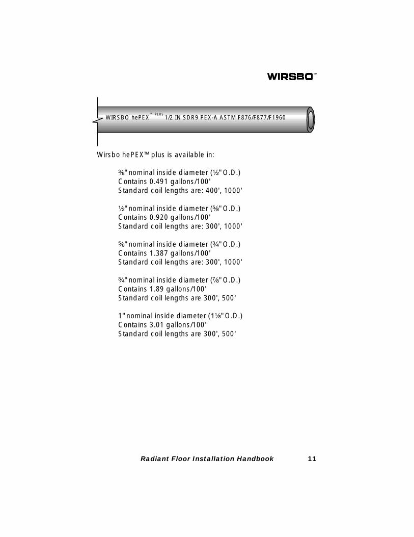
Wirsbo hePEX™plus is available in:
³⁄₈" nominal inside diameter (¹⁄₂" O.D.)Contains 0.491 gallons/100'Standard coil lengths are: 400', 1000'
¹⁄₂" nominal inside diameter (⁵⁄₈" O.D.)Contains 0.920 gallons/100'Standard coil lengths are: 300', 1000'
⁵⁄₈" nominal inside diameter (³⁄₄" O.D.)Contains 1.387 gallons/100'Standard coil lengths are: 300', 1000'
³⁄₄" nominal inside diameter (⁷⁄₈" O.D.)Contains 1.89 gallons/100'Standard coil lengths are 300', 500'
1" nominal inside diameter (1¹⁄₈" O.D.)Contains 3.01 gallons/100'Standard coil lengths are 300', 500'
WIRSBO hePEX™ PLUS
1/2 IN SDR9 PEX-A ASTM F876/F877/F1960
12 Radiant Floor Installation Handbook
SECTION 3: WORKING WITH PEX
PEX tubing is engineered as a very workable and forgiving con-struction material. The following procedures and methods arerecommended to simplify installation and help the installer avoidmistakes that could damage the product or otherwise complicatethe project.
Storing Wirsbo PEX TubingPEX tubing must be stored under cover to avoid extended expo-sure to direct sunlight (diffused light does not pose a concern).Ultraviolet light can cause accelerated aging. Never install tubingthat is suspect of being exposed to direct sunlight for more than30 days. Exposure to sunlight during normal installation is notharmful. Care should always be taken to ensure that abuse ormishandling is avoided. Wirsbo PEX tubing is shipped in indi-vidual boxes. Please save boxes for storage of unused lengths.
TemperatureWirsbo PEX tubing is very flexible, however, it is more rigid towork with at temperatures below 40° F. Installation is simplifiedwhen the PEX tubing coils are warmed to a temperature above60° F.
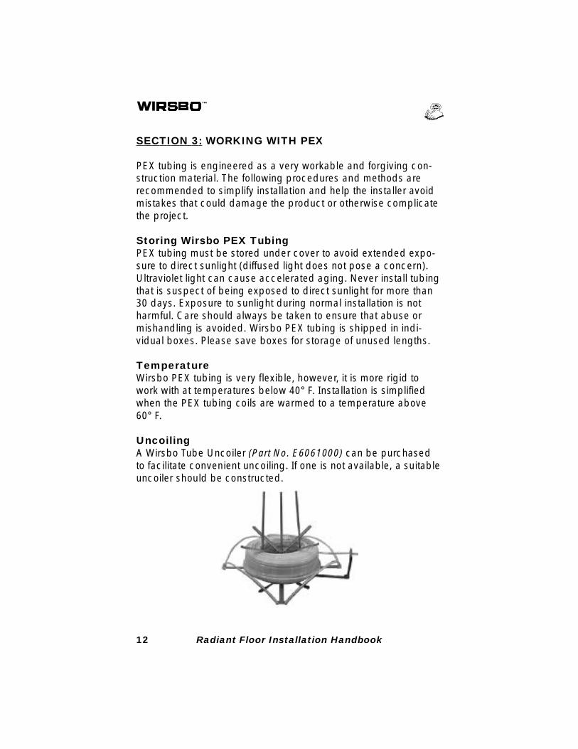
UncoilingA Wirsbo Tube Uncoiler (Part No. E6061000) can be purchasedto facilitate convenient uncoiling. If one is not available, a suitableuncoiler should be constructed.
13Radiant Floor Installation Handbook
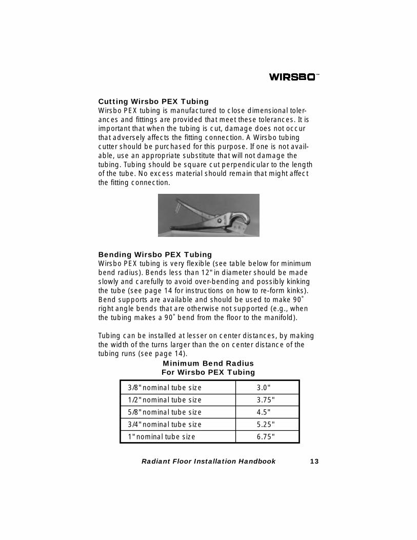
Cutting Wirsbo PEX TubingWirsbo PEX tubing is manufactured to close dimensional toler-ances and fittings are provided that meet these tolerances. It isimportant that when the tubing is cut, damage does not occurthat adversely affects the fitting connection. A Wirsbo tubingcutter should be purchased for this purpose. If one is not avail-able, use an appropriate substitute that will not damage thetubing. Tubing should be square cut perpendicular to the lengthof the tube. No excess material should remain that might affectthe fitting connection.
Bending Wirsbo PEX TubingWirsbo PEX tubing is very flexible (see table below for minimumbend radius). Bends less than 12" in diameter should be madeslowly and carefully to avoid over-bending and possibly kinkingthe tube (see page 14 for instructions on how to re-form kinks).Bend supports are available and should be used to make 90˚right angle bends that are otherwise not supported (e.g., whenthe tubing makes a 90˚ bend from the floor to the manifold).
Tubing can be installed at lesser on center distances, by makingthe width of the turns larger than the on center distance of thetubing runs (see page 14).
Minimum Bend RadiusFor Wirsbo PEX Tubing
3/8" nominal tube size 3.0"
1/2" nominal tube size 3.75"
5/8" nominal tube size 4.5"
3/4" nominal tube size 5.25"
1" nominal tube size 6.75"
14 Radiant Floor Installation Handbook
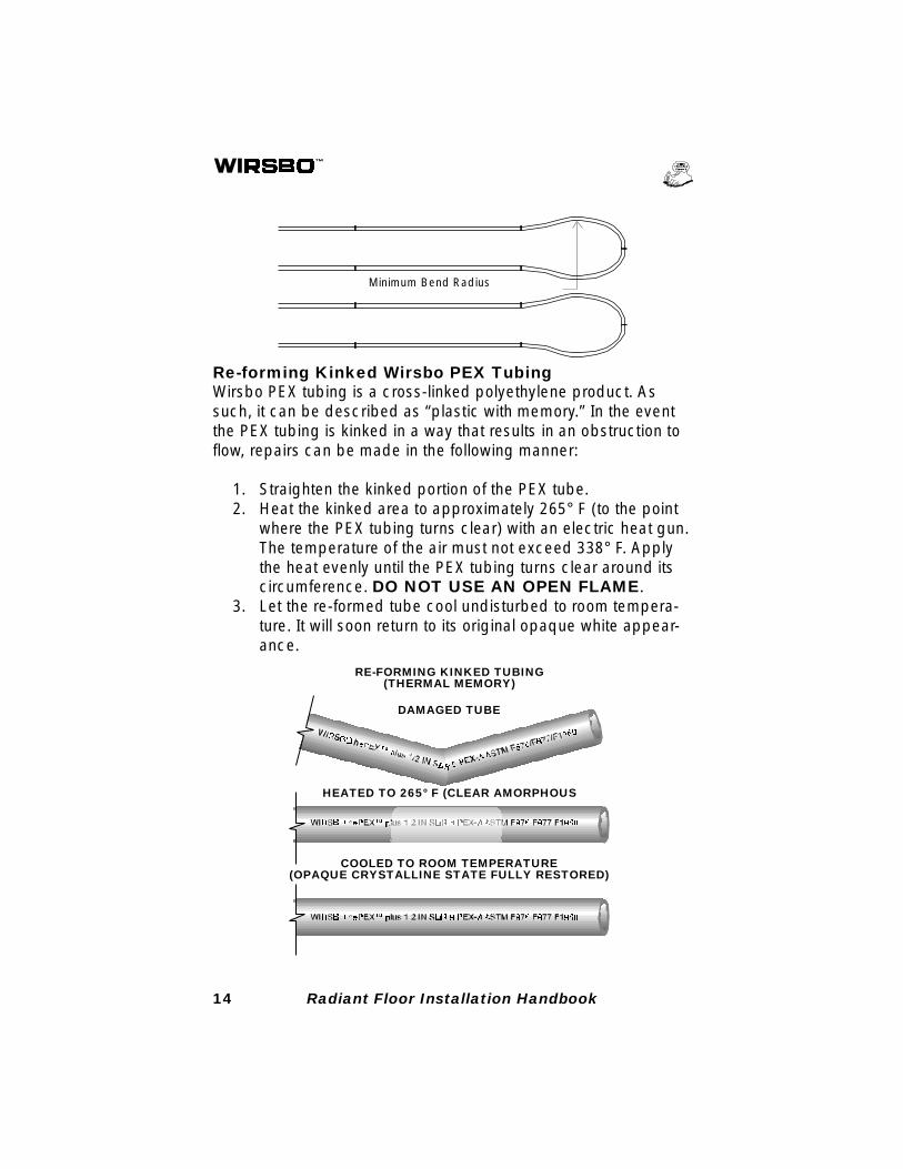
Re-forming Kinked Wirsbo PEX TubingWirsbo PEX tubing is a cross-linked polyethylene product. Assuch, it can be described as “plastic with memory.” In the eventthe PEX tubing is kinked in a way that results in an obstruction toflow, repairs can be made in the following manner:
1. Straighten the kinked portion of the PEX tube.2. Heat the kinked area to approximately 265° F (to the point
where the PEX tubing turns clear) with an electric heat gun.The temperature of the air must not exceed 338° F. Applythe heat evenly until the PEX tubing turns clear around itscircumference. DO NOT USE AN OPEN FLAME.
3. Let the re-formed tube cool undisturbed to room tempera-ture. It will soon return to its original opaque white appear-ance.
Minimum Bend Radius
RE-FORMING KINKED TUBING(THERMAL MEMORY)
DAMAGED TUBE
HEATED TO 265° F (CLEAR AMORPHOUS
COOLED TO ROOM TEMPERATURE(OPAQUE CRYSTALLINE STATE FULLY RESTORED)
15Radiant Floor Installation Handbook
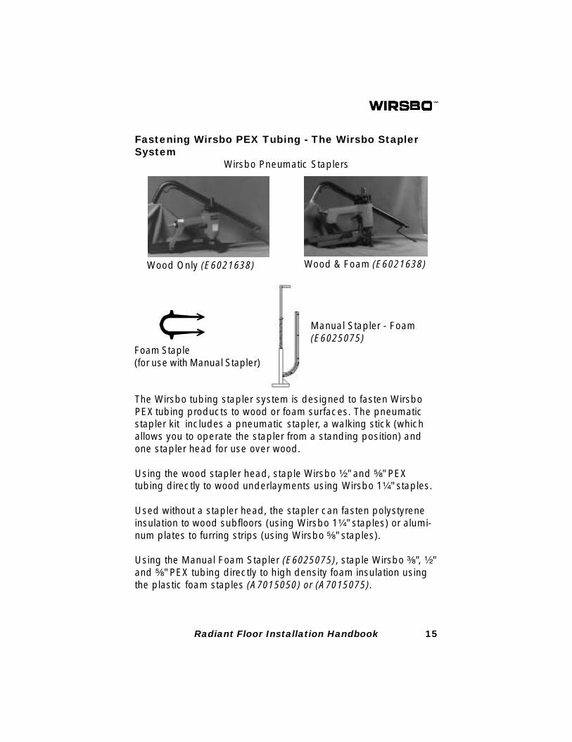
Fastening Wirsbo PEX Tubing - The Wirsbo StaplerSystem
The Wirsbo tubing stapler system is designed to fasten WirsboPEX tubing products to wood or foam surfaces. The pneumaticstapler kit includes a pneumatic stapler, a walking stick (whichallows you to operate the stapler from a standing position) andone stapler head for use over wood.
Using the wood stapler head, staple Wirsbo ¹⁄₂" and ⁵⁄₈" PEXtubing directly to wood underlayments using Wirsbo 1¹⁄₄" staples.
Used without a stapler head, the stapler can fasten polystyreneinsulation to wood subfloors (using Wirsbo 1¹⁄₄" staples) or alumi-num plates to furring strips (using Wirsbo ⁵⁄₈" staples).
Using the Manual Foam Stapler (E6025075), staple Wirsbo ³⁄₈", ¹⁄₂"and ⁵⁄₈" PEX tubing directly to high density foam insulation usingthe plastic foam staples (A7015050) or (A7015075).
Wirsbo Pneumatic Staplers
Wood Only (E6021638) Wood & Foam (E6021638)
Manual Stapler - Foam(E6025075)
Foam Staple(for use with Manual Stapler)
16 Radiant Floor Installation Handbook
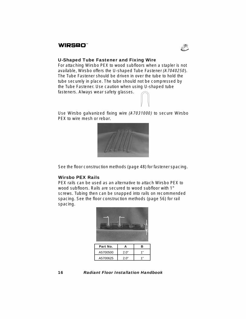
U-Shaped Tube Fastener and Fixing WireFor attaching Wirsbo PEX to wood subfloors when a stapler is notavailable, Wirsbo offers the U-shaped Tube Fastener (A7040250).The Tube Fastener should be driven in over the tube to hold thetube securely in place. The tube should not be compressed bythe Tube Fastener. Use caution when using U-shaped tubefasteners. Always wear safety glasses.
Part No. A B
A5700500 2.0" 1"
A5700625 2.0" 1"
Use Wirsbo galvanized fixing wire (A7031000) to secure WirsboPEX to wire mesh or rebar.
See the floor construction methods (page 48) for fastener spacing.
Wirsbo PEX RailsPEX rails can be used as an alternative to attach Wirsbo PEX towood subfloors. Rails are secured to wood subfloor with 1"screws. Tubing then can be snapped into rails on recommendedspacing. See the floor construction methods (page 56) for railspacing.
17Radiant Floor Installation Handbook
Protect PEX Tubing from FreezingPEX tubing not buried in concrete is highly tolerant to freezeconditions and normally will not burst. Precautions must be takento avoid freezing when PEX tubing is embedded in concrete.When pressure testing with water, DO NOT allow the water tofreeze. If the area experiences frequent power outages or if thestructure is used intermittently, a suitable mixture of water andpropylene glycol should be used in the system.
Other Handling Precautions
• DO NOT use PEX tubing where temperatures and pres-sures exceed product ratings.
• DO NOT apply an open flame to PEX tubing.• DO NOT solder within 18" of PEX tubing in the same water
line.• DO NOT install PEX tubing where it will come in direct
contact with high concentrations of low molecular weightpetroleum products, such as fuels or solvents.
• DO NOT install PEX tubing in direct contact with sharp fill.• DO NOT weld or glue Wirsbo PEX.• DO NOT install Wirsbo PEX within 6" of any gas appliance
vents or within 12" of any un insulated recessed lightfixtures.
• DO NOT use Wirsbo PEX to convey natural gas.• DO NOT use Wirsbo PEX tubing for an electrical ground.
18 Radiant Floor Installation Handbook
SECTION 4: FITTINGS
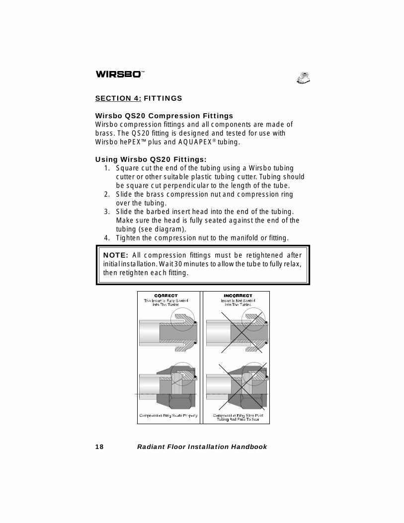
Wirsbo QS20 Compression FittingsWirsbo compression fittings and all components are made ofbrass. The QS20 fitting is designed and tested for use withWirsbo hePEX™plus and AQUAPEX® tubing.
Using Wirsbo QS20 Fittings:1. Square cut the end of the tubing using a Wirsbo tubing
cutter or other suitable plastic tubing cutter. Tubing shouldbe square cut perpendicular to the length of the tube.
2. Slide the brass compression nut and compression ringover the tubing.
3. Slide the barbed insert head into the end of the tubing.Make sure the head is fully seated against the end of thetubing (see diagram).
4. Tighten the compression nut to the manifold or fitting.
NOTE: All compression fittings must be retightened afterinitial installation. Wait 30 minutes to allow the tube to fully relax,then retighten each fitting.
19Radiant Floor Installation Handbook
Connecting QS20 Fittings to the Wirsbo Manifold1. Cut tubing even with the bottom thread on the manifold
nipple as shown in the diagram below.2. Slide compression nut, compression ring and QS20 barbed
insert onto tubing as described above.3. Tighten compression nut securely onto the manifold nipple.
NOTE: When installing a fitting onto the manifold or a repaircoupling, leave a little slack in the tubing. This will allow the endof the tubing to move inward toward the manifold or couplingwhen the fitting is tightened. If the tubing is taut and can't move,the barbed insert head could pull out of the tubing while the nutis being tightened and result in a leak.
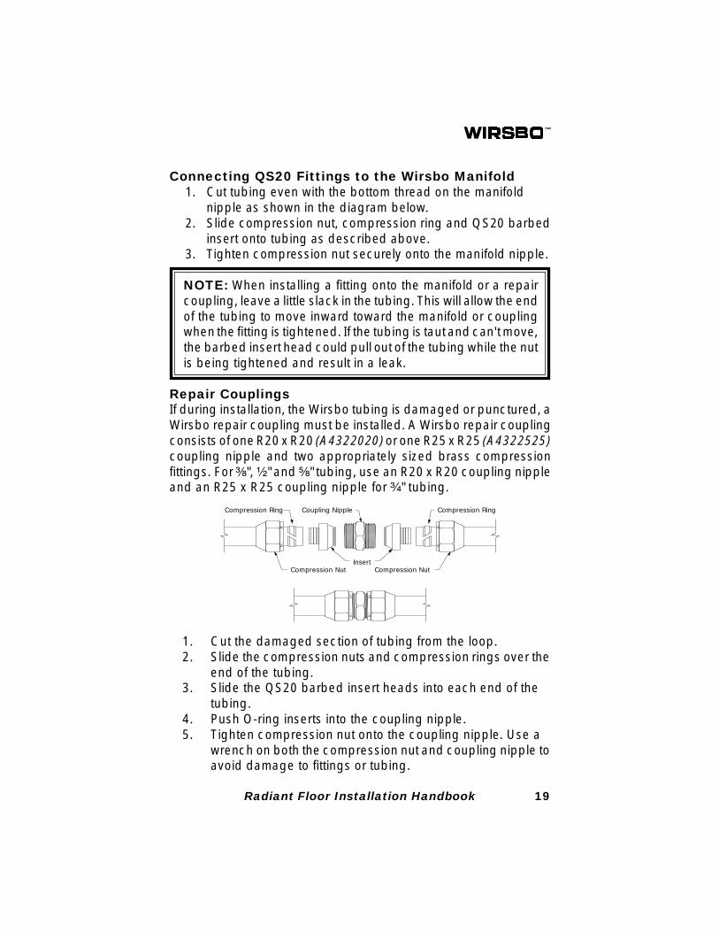
Repair CouplingsIf during installation, the Wirsbo tubing is damaged or punctured, aWirsbo repair coupling must be installed. A Wirsbo repair couplingconsists of one R20 x R20 (A4322020) or one R25 x R25 (A4322525)coupling nipple and two appropriately sized brass compressionfittings. For ³⁄₈", ¹⁄₂" and ⁵⁄₈" tubing, use an R20 x R20 coupling nippleand an R25 x R25 coupling nipple for ³⁄₄" tubing.
Compression Nut
Compression Ring
Insert
Coupling Nipple
Compression Nut
Compression Ring
1. Cut the damaged section of tubing from the loop.2. Slide the compression nuts and compression rings over the
end of the tubing.3. Slide the QS20 barbed insert heads into each end of the
tubing.4. Push O-ring inserts into the coupling nipple.5. Tighten compression nut onto the coupling nipple. Use a
wrench on both the compression nut and coupling nipple toavoid damage to fittings or tubing.
20 Radiant Floor Installation Handbook
NOTE: Wirsbo repair couplings will replace about 1" of tubing.If the damaged section of tubing is longer than 1", and you haveno excess tubing in the line, you will need to use two repaircouplings and a length of PEX tubing to replace the damagedsection of pipe.
Caution: When tightening the compression nut onto the brasscoupling nipple, always use two wrenches: one on the com-pression nut and one on the hex nut on the coupling nipple.Never tighten one compression nut against the other withoutsecurely holding the hex nut. This could damage both the fittingand the tubing.
Important: All compression fittings must be retightened afterinitial installation. Wait at least 30 minutes to allow the tubing tofully relax, and then retighten each fitting.
NOTE: All reasonable measures should be taken to avoidcouplings in a concrete slab. If it is necessary, the repaircoupling should be wrapped with insulation to prevent directcontact with the concrete.
Wirsbo ProPEX® Fittings and Tools
Wirsbo ProPEX® fittings rely on the shape memory of Wirsbo
AQUAPEX® and Wirsbo hePEX™plus tubing. The ProPEX
® Hand
Tool (Q6305075) and the ProPEX® Air Expander Tool (Q6301000)
expand the tubing enough to insert the ProPEX® fitting. The tubing
then squeezes around the fitting as it returns to its original shape.
The ProPEX® Hand Expander Tool
The complete kit consists of:• 1 two-handled expander tool• 3 expander heads: one each for ¹⁄₂", ³⁄₄", and 1" PEX tubing.
(³⁄₈" and ⁵⁄₈" expander heads are sold separately.)• 1 tube of tool lubricant• 1 ProPEX® tool case
21Radiant Floor Installation Handbook
Proper Maintenance for the ProPEX® Hand Expander Tool
1. Store the tool and expander heads in the case. Store thetool with an expansion head in place to protect the internaldriver. Unscrew the head slightly so the handles cometogether. Be sure to retighten the expander head beforeuse.
2. Periodically remove the head and clean the cone of theProPEX® Hand Expander Tool using a dry, lint-free cloth.
3. Periodically clean the inside of the expander heads using adry, lint-free cloth. This will remove any debris that may betrapped between the head and cone.
4. To keep internal parts working smoothly, apply a thin coatof lubricant to the internal cone. Lubricant should beapplied daily with regular use. Keep all other parts of thetool free from grease.
Caution: Excessive lubrication may result in improper con-nections. Only a small amount of lubricant is necessary to keepthe tool working properly.
The ProPEX® Air Expander Tool
Wirsbo ProPEX® Air Expander Tool (Q6301000) uses air pressure to
make fast, easy connections to ³⁄₈", ¹⁄₂", ⁵⁄₈" and ³⁄₄" hePEX™plus andAQUAPEX
® tubing.
NOTE: The ProPEX® Air Expander Tool is NOT designed for
use with 1" tubing and fittings.
The complete kit consists of:• 1 ProPEX® Air Expander Tool• ¹⁄₂" expander head (³⁄₈", ⁵⁄₈" and ³⁄₄" expander heads are
sold separately.)• 1 tube of tool lubricant• 1 instruction manual• 1 carrying case
22 Radiant Floor Installation Handbook
Tool SpecificationsThe Wirsbo ProPEX
® Air Expander Tool is rated for use at 80-90 psi.
Do not operate the tool above 100 psi as high pressures can bedangerous.
Pressure: 80-90 psi working pressureConsumption: 4 CFMCapacity: ³⁄₈" to ³⁄₄" tubingConnection Size: ¹⁄₄" male quick connect fittingWeight: 5.5 lbs./ProPEX
® Air Expander Tool
7.0 lbs./ProPEX® Air Expander Tool, expander
head, lubricant, instructional manual andcarrying case
Operating Instructions1. Attach the correct sized expander head to the ProPEX® Air
Expander Tool. Be sure the head is screwed on tightly.2. Make sure the air compressor regulator is set between 80
to 90 psi. (Do not exceed 100 psi.)3. Attach air supply to the tool.
NOTE: Prior to each use, check the cone for dirt and cleanas listed below. Add one to two drops of oil to the inlet of theProPEX
® Air Expander Tool to lubricate the tool.
Proper Tool Maintenance1. Store the ProPEX® Air Expander Tool in a dry location to
prevent rust. The ProPEX® Air Expander Tool is shippedwith one ¹⁄₂" expander head attached to it. Store theProPEX® Air Expander Tool with the expander head inplace to prevent damage to the expander cone.
2. Periodically remove the head and clean the cone of theProPEX® Air Expander Tool using a dry, lint-free cloth.
3. Periodically clean the inside of the expander heads using adry cloth. This will remove any debris that may be trappedbetween the head and cone.
4. To keep internal parts working smoothly, apply a thin coatof lubricant to the internal cone. Apply the lubricant with alint-free cloth.

23Radiant Floor Installation Handbook
Caution: Excessive lubrication may result in improper con-nections. Only a small amount of lubricant is necessary to keepthe tool working properly.
NOTE: Review of the Safety and Operational Guidelines in theProPEX
® Air Expander Tool Manual is strongly recommended
before using the tool.
Using ProPEX® Fittings
1. Screw the proper expander head size completely onto theProPEX® Air Expander Tool. Be sure the expander headcorresponds with the tubing size.
2. Square cut PEX tubing perpendicular to the length of thetubing using a cutter designed for plastic tubing.
3. Remove all excess material or burrs that may compromisethe fitting connection.
Proper PEX Cutting Procedures
NOTE: hePEX™plus and AQUAPEX ®
are manufactured toclose dimensional tolerances and fittings are provided to meetthose tolerances. Cut the tubing as described in Step 2 to avoiddamage. A Wirsbo tubing cutter may be purchased for thispurpose. If one is not available, use an appropriate substitute.
24 Radiant Floor Installation Handbook
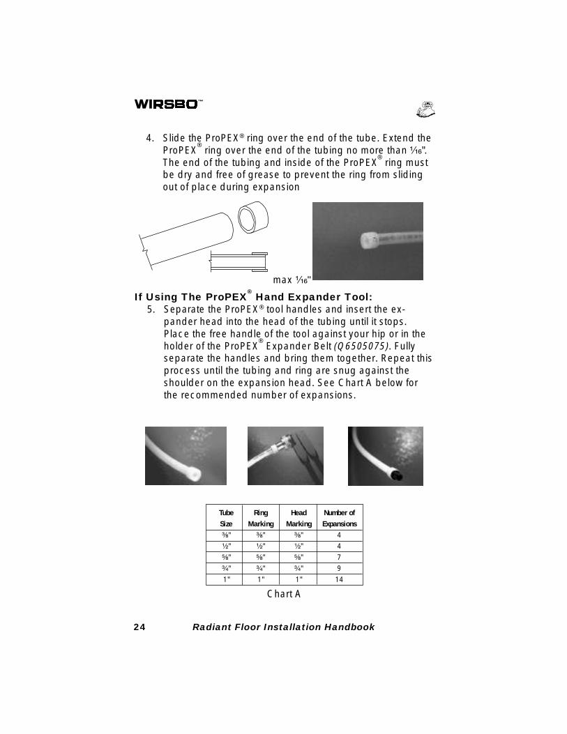
4. Slide the ProPEX® ring over the end of the tube. Extend theProPEX
® ring over the end of the tubing no more than ¹⁄₁₆".
The end of the tubing and inside of the ProPEX® ring must
be dry and free of grease to prevent the ring from slidingout of place during expansion
If Using The ProPEX® Hand Expander Tool:
5. Separate the ProPEX® tool handles and insert the ex-pander head into the head of the tubing until it stops.Place the free handle of the tool against your hip or in theholder of the ProPEX
® Expander Belt (Q6505075). Fully
separate the handles and bring them together. Repeat thisprocess until the tubing and ring are snug against theshoulder on the expansion head. See Chart A below forthe recommended number of expansions.
max ¹⁄₁₆"
Chart A
Tube Ring Head Number ofSize Marking Marking Expansions³⁄₈" ³⁄₈" ³⁄₈" 4
¹⁄₂" ¹⁄₂" ¹⁄₂" 4
⁵⁄₈" ⁵⁄₈" ⁵⁄₈" 7
³⁄₄" ³⁄₄" ³⁄₄" 9
1" 1" 1" 14
25Radiant Floor Installation Handbook
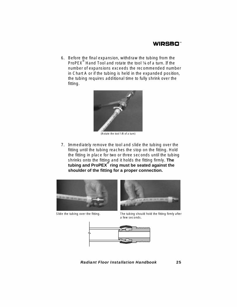
(Rotate the tool 1/8 of a turn)
6. Before the final expansion, withdraw the tubing from theProPEX
® Hand Tool and rotate the tool ¹⁄₈ of a turn. If the
number of expansions exceeds the recommended numberin Chart A or if the tubing is held in the expanded position,the tubing requires additional time to fully shrink over thefitting.
7. Immediately remove the tool and slide the tubing over thefitting until the tubing reaches the stop on the fitting. Holdthe fitting in place for two or three seconds until the tubingshrinks onto the fitting and it holds the fitting firmly. Thetubing and ProPEX
® ring must be seated against the
shoulder of the fitting for a proper connection.
Slide the tubing over the fitting. The tubing should hold the fitting firmly aftera few seconds.
26 Radiant Floor Installation Handbook
NOTE: Chart A is the recommended number of expansions.The correct number of expansions is the number it takes for thetubing and the shoulder of the expander head to fit snuglyagainst each other. The goal in achieving a proper connectionis to shrink the tubing and ProPEX
® Ring immediately around
the fitting.
NOTE: Full expansions are necessary for a proper connec-tion. Making half expansions or deviating from the recom-mended expansion method may result in improper connec-tions. If the fitting does not slide into the tubing all the way to thestop, immediately remove it from the tubing and expand thetubing one final time. To avoid over-expanding the tubing, donot hold the tubing in the expanded position.
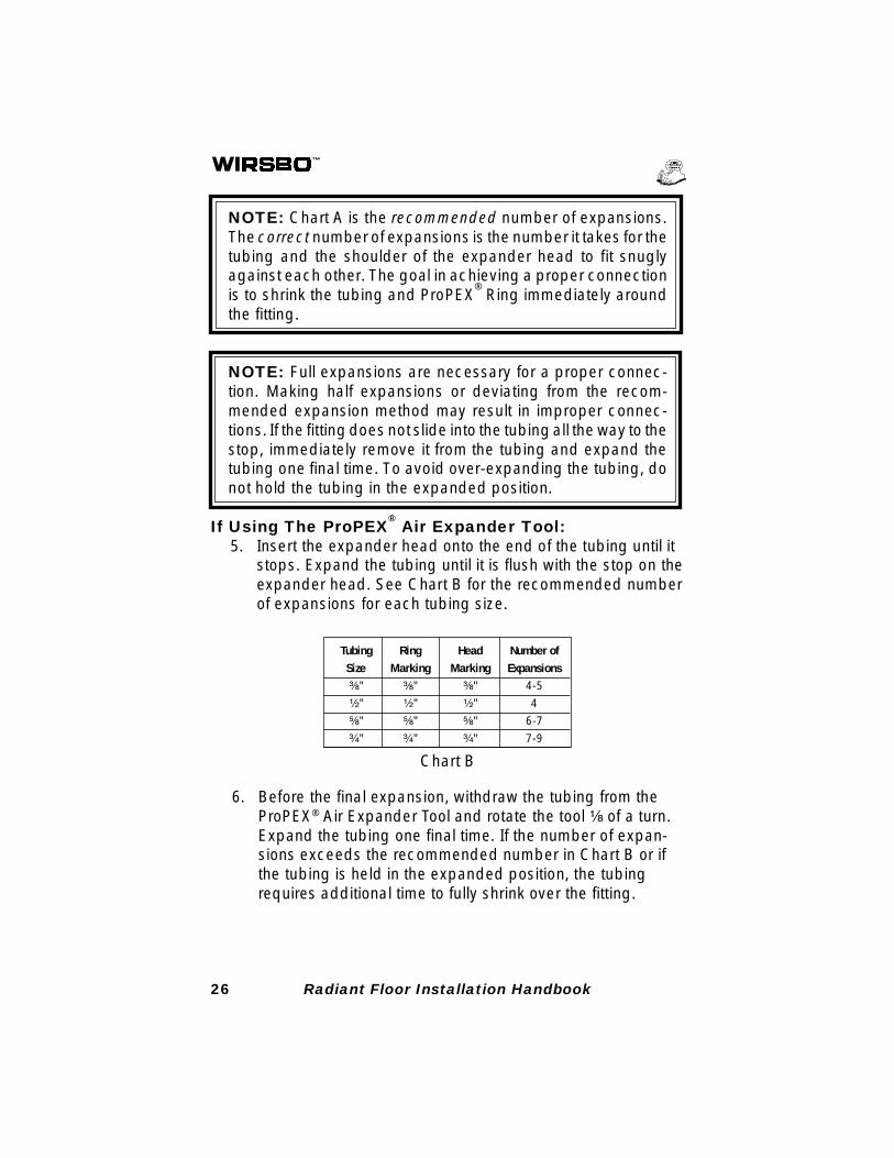
If Using The ProPEX® Air Expander Tool:
5. Insert the expander head onto the end of the tubing until itstops. Expand the tubing until it is flush with the stop on theexpander head. See Chart B for the recommended numberof expansions for each tubing size.
Chart B
6. Before the final expansion, withdraw the tubing from theProPEX® Air Expander Tool and rotate the tool ¹⁄₈ of a turn.Expand the tubing one final time. If the number of expan-sions exceeds the recommended number in Chart B or ifthe tubing is held in the expanded position, the tubingrequires additional time to fully shrink over the fitting.
Tubing Ring Head Number ofSize Marking Marking Expansions³⁄₈" ³⁄₈" ³⁄₈" 4-5
¹⁄₂" ¹⁄₂" ¹⁄₂" 4
⁵⁄₈" ⁵⁄₈" ⁵⁄₈" 6-7
³⁄₄" ³⁄₄" ³⁄₄" 7-9
27Radiant Floor Installation Handbook
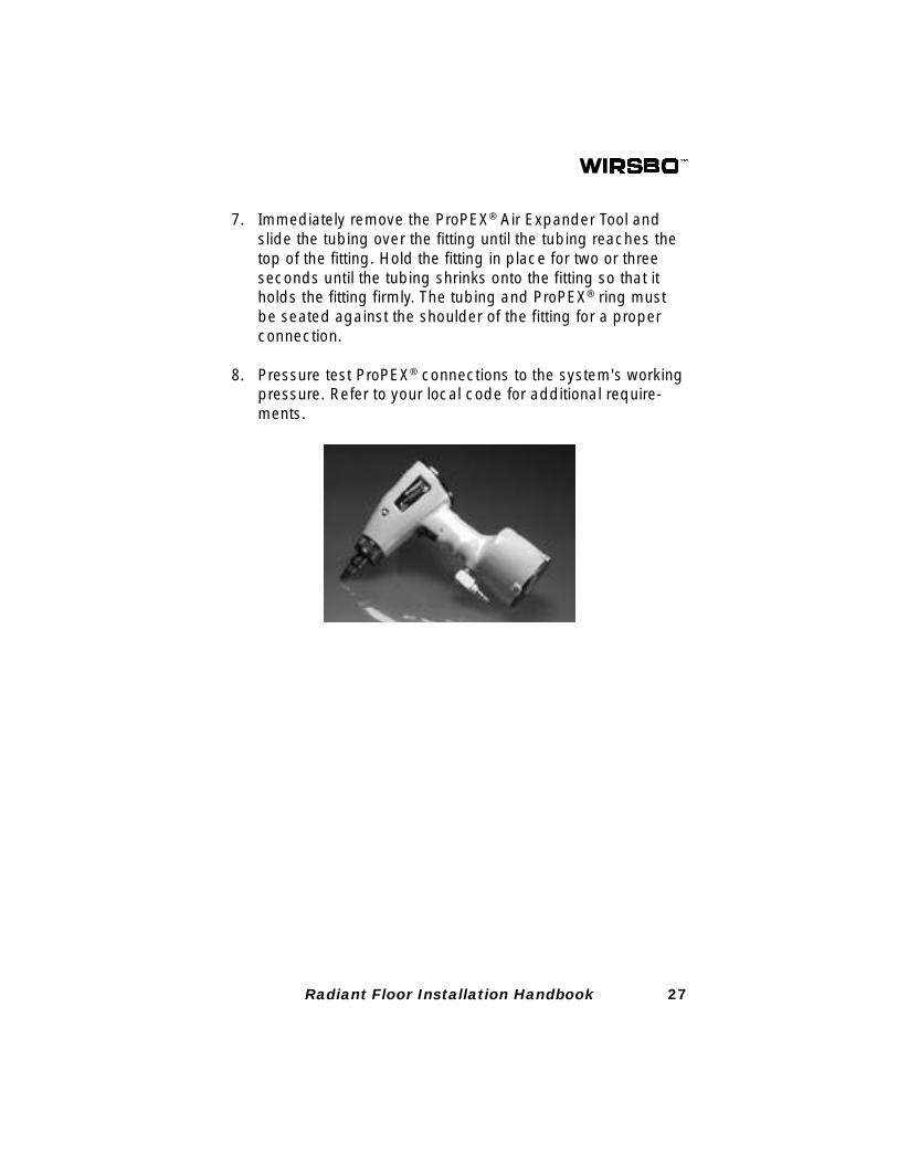
7. Immediately remove the ProPEX® Air Expander Tool andslide the tubing over the fitting until the tubing reaches thetop of the fitting. Hold the fitting in place for two or threeseconds until the tubing shrinks onto the fitting so that itholds the fitting firmly. The tubing and ProPEX® ring mustbe seated against the shoulder of the fitting for a properconnection.
8. Pressure test ProPEX® connections to the system's workingpressure. Refer to your local code for additional require-ments.
28 Radiant Floor Installation Handbook
SECTION 5: WIRSBO BRASS MANIFOLD
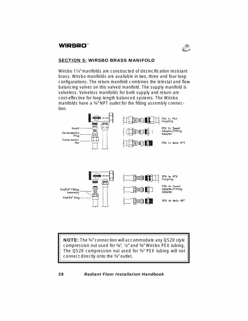
Wirsbo 1¹⁄₄" manifolds are constructed of dezincification resistantbrass. Wirsbo manifolds are available in two, three and four loopconfigurations. The return manifold combines the telestat and flowbalancing valves on this valved manifold. The supply manifold isvalveless. Valveless manifolds for both supply and return arecost-effective for loop length balanced systems. The Wirsbomanifolds have a ³⁄₄" NPT outlet for the fitting assembly connec-tion.
NOTE: The ³⁄₄" connection will accommodate any QS20 stylecompression nut used for ³⁄₈", ¹⁄₂" and ⁵⁄₈" Wirsbo PEX tubing.The QS20 compression nut used for ³⁄₄" PEX tubing will notconnect directly onto the ³⁄₄" outlet.
29Radiant Floor Installation Handbook
Plan Manifold Locations and Rough In Requirements1. Manifolds should be located on an interior wall whenever
possible. Manifolds mounted on exterior walls may experi-ence significant heat loss. Installing a manifold on aninterior wall makes it more accessible to the floor area. Onan interior wall, tubing can be routed to the floor in front ofor behind the manifold.
2. Select a location that allows the use of hallways or largerooms as avenues for the leaders to run to and from distantrooms. The inside of a closet is an ideal manifold location.
3. The location should permit easy connection to supply andreturn lines from the heat source.
4. The location should permit easy access for maintenance.
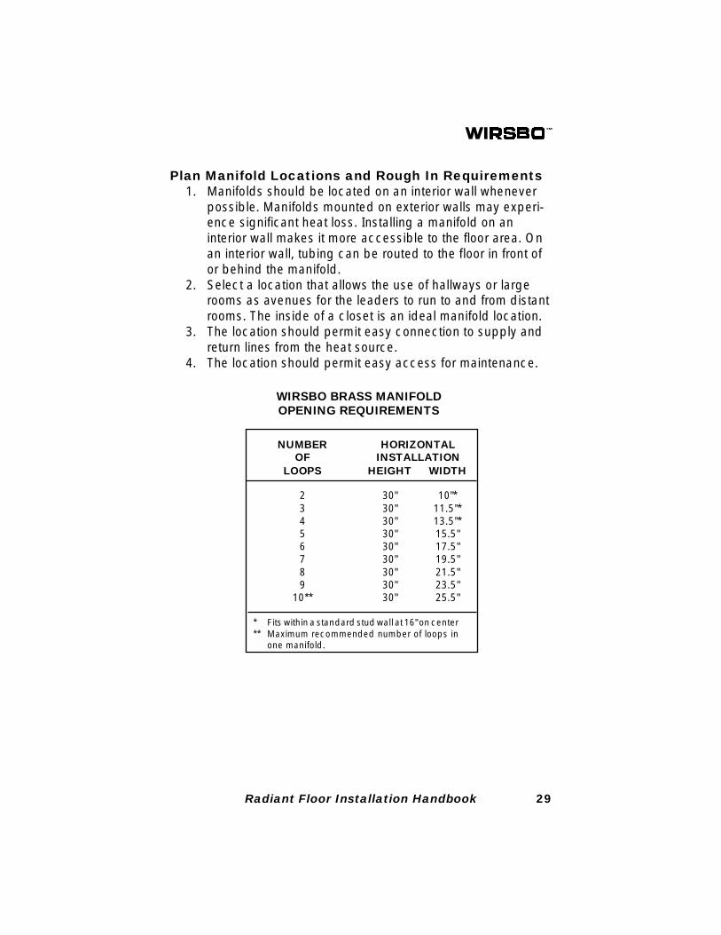
WIRSBO BRASS MANIFOLDOPENING REQUIREMENTS
NUMBER HORIZONTALOF INSTALLATION
2 30" 10"*3 30" 11.5"*4 30" 13.5"*5 30" 15.5"6 30" 17.5"7 30" 19.5"8 30" 21.5"9 30" 23.5"
10** 30" 25.5"
* Fits within a standard stud wall at 16" on center** Maximum recommended number of loops in
one manifold.
LOOPS HEIGHT WIDTH
30 Radiant Floor Installation Handbook
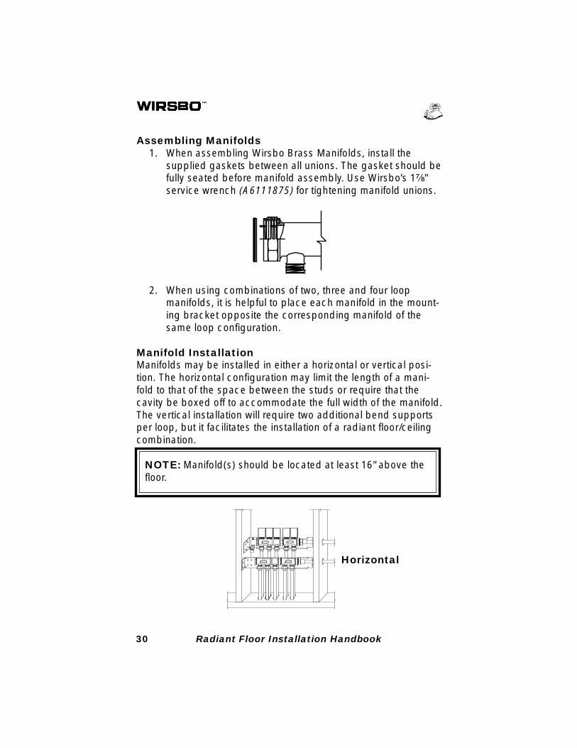
Assembling Manifolds1. When assembling Wirsbo Brass Manifolds, install the
supplied gaskets between all unions. The gasket should befully seated before manifold assembly. Use Wirsbo’s 1⁷⁄₈"service wrench (A6111875) for tightening manifold unions.
Horizontal
N N
N N
2. When using combinations of two, three and four loopmanifolds, it is helpful to place each manifold in the mount-ing bracket opposite the corresponding manifold of thesame loop configuration.
Manifold InstallationManifolds may be installed in either a horizontal or vertical posi-tion. The horizontal configuration may limit the length of a mani-fold to that of the space between the studs or require that thecavity be boxed off to accommodate the full width of the manifold.The vertical installation will require two additional bend supportsper loop, but it facilitates the installation of a radiant floor/ceilingcombination.
NOTE: Manifold(s) should be located at least 16" above thefloor.
31Radiant Floor Installation Handbook
Horizontal Vertical
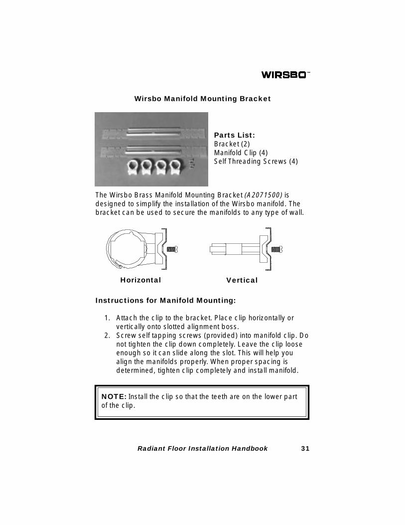
Parts List:Bracket (2)Manifold Clip (4)Self Threading Screws (4)
Wirsbo Manifold Mounting Bracket
The Wirsbo Brass Manifold Mounting Bracket (A2071500) isdesigned to simplify the installation of the Wirsbo manifold. Thebracket can be used to secure the manifolds to any type of wall.
Instructions for Manifold Mounting:
1. Attach the clip to the bracket. Place clip horizontally orvertically onto slotted alignment boss.
2. Screw self tapping screws (provided) into manifold clip. Donot tighten the clip down completely. Leave the clip looseenough so it can slide along the slot. This will help youalign the manifolds properly. When proper spacing isdetermined, tighten clip completely and install manifold.
NOTE: Install the clip so that the teeth are on the lower partof the clip.
32 Radiant Floor Installation Handbook
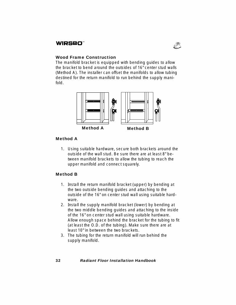
Wood Frame ConstructionThe manifold bracket is equipped with bending guides to allowthe bracket to bend around the outsides of 16" center stud walls(Method A). The installer can offset the manifolds to allow tubingdestined for the return manifold to run behind the supply mani-fold.
Method A Method B
Method A
1. Using suitable hardware, secure both brackets around theoutside of the wall stud. Be sure there are at least 8" be-tween manifold brackets to allow the tubing to reach theupper manifold and connect squarely.
Method B
1. Install the return manifold bracket (upper) by bending atthe two outside bending guides and attaching to theoutside of the 16" on center stud wall using suitable hard-ware.
2. Install the supply manifold bracket (lower) by bending atthe two middle bending guides and attaching to the insideof the 16" on center stud wall using suitable hardware.Allow enough space behind the bracket for the tubing to fit(at least the O.D. of the tubing). Make sure there are atleast 10" in between the two brackets.
3. The tubing for the return manifold will run behind thesupply manifold.
33Radiant Floor Installation Handbook
NOTE: Do not tighten compression fittings on the manifoldsolely against manifold support bracket. Hold the manifoldwhile tightening fittings.
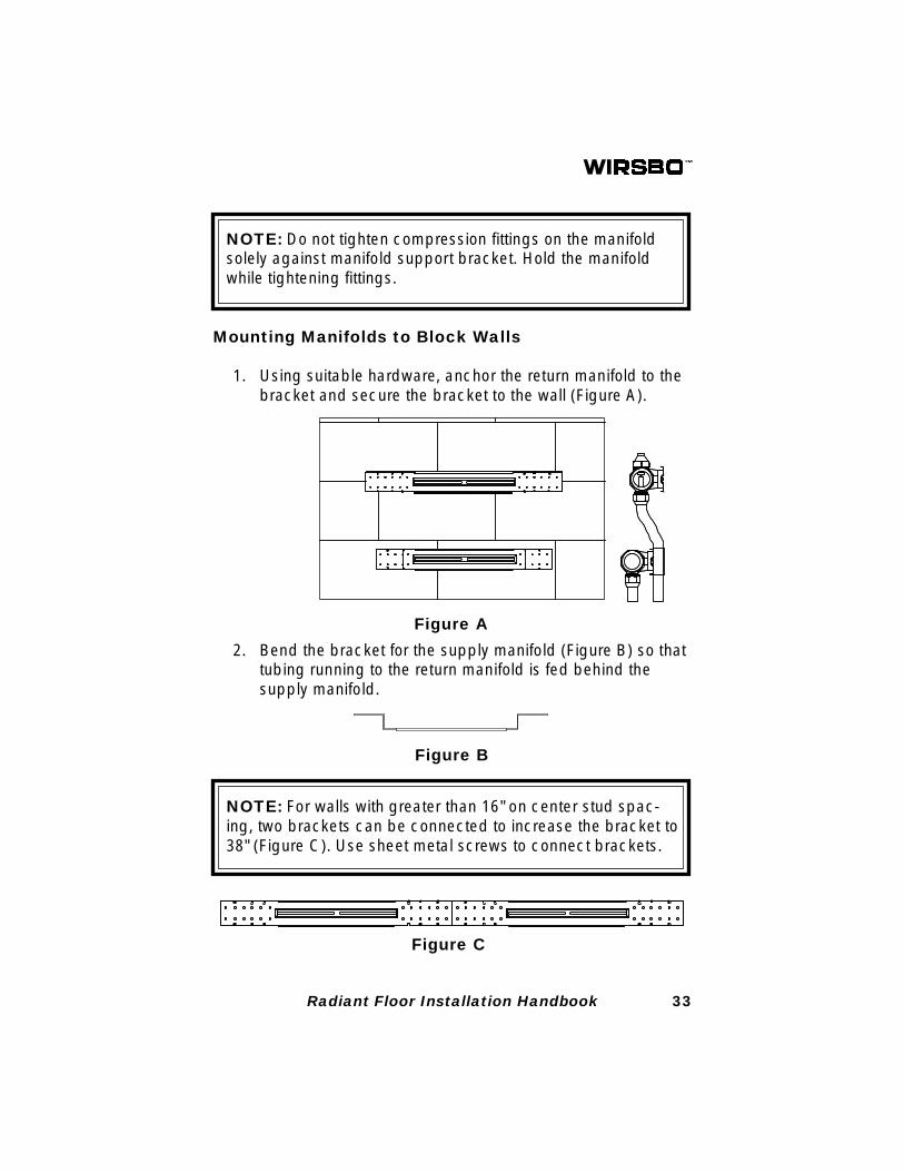
Mounting Manifolds to Block Walls
1. Using suitable hardware, anchor the return manifold to thebracket and secure the bracket to the wall (Figure A).
2. Bend the bracket for the supply manifold (Figure B) so thattubing running to the return manifold is fed behind thesupply manifold.
Figure C
Figure B
Figure A
NOTE: For walls with greater than 16" on center stud spac-ing, two brackets can be connected to increase the bracket to38" (Figure C). Use sheet metal screws to connect brackets.
34 Radiant Floor Installation Handbook
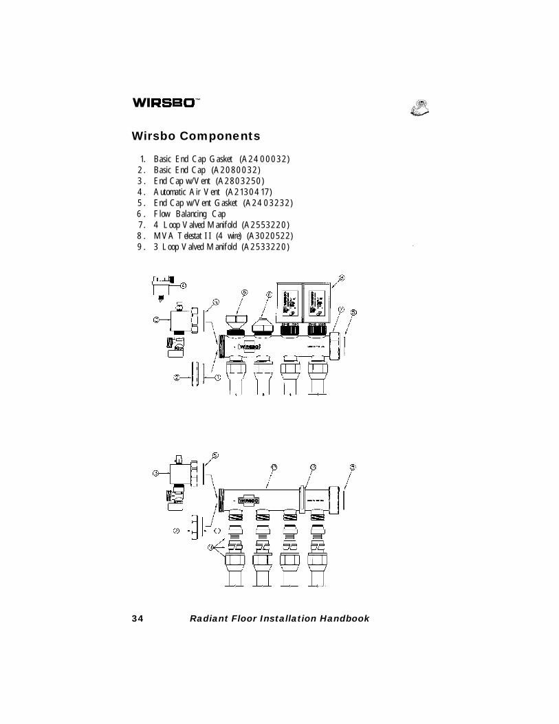
Wirsbo Components
1. Basic End Cap Gasket (A2400032)2 . Basic End Cap (A2080032)3 . End Cap w/Vent (A2803250)4. Automatic Air Vent (A2130417)5 . End Cap w/Vent Gasket (A2403232)6 . Flow Balancing Cap7. 4 Loop Valved Manifold (A2553220)8 . MVA Telestat II (4 wire) (A3020522)9 . 3 Loop Valved Manifold (A2533220)
35Radiant Floor Installation Handbook
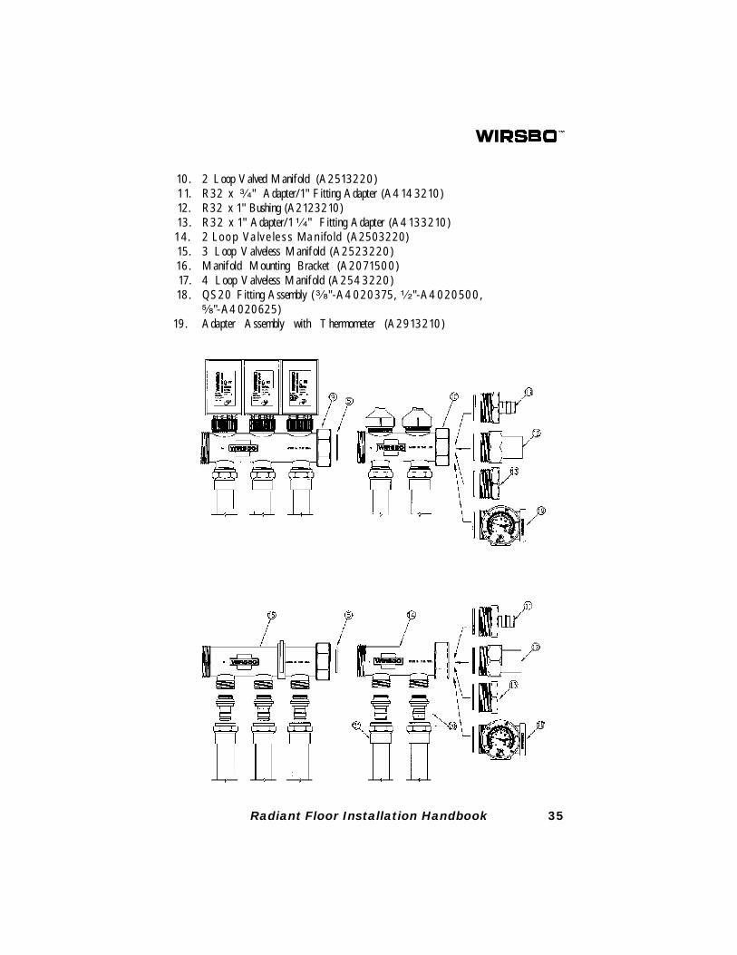
10. 2 Loop Valved Manifold (A2513220)11. R32 x ³⁄₄" Adapter/1" Fitting Adapter (A4143210)12. R32 x 1" Bushing (A2123210)13. R32 x 1" Adapter/1¹⁄₄" Fitting Adapter (A4133210)14. 2 Loop Valveless Manifold (A2503220)15. 3 Loop Valveless Manifold (A2523220)16. Manifold Mounting Bracket (A2071500)17. 4 Loop Valveless Manifold (A2543220)18. QS20 Fitting Assembly (³⁄₈"-A4020375, ¹⁄₂"-A4020500,
⁵⁄₈"-A4020625)19. Adapter Assembly with Thermometer (A2913210)
36 Radiant Floor Installation Handbook
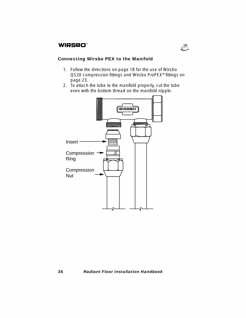
Connecting Wirsbo PEX to the Manifold
1. Follow the directions on page 18 for the use of WirsboQS20 compression fittings and Wirsbo ProPEX® fittings onpage 23.
2. To attach the tube to the manifold properly, cut the tubeeven with the bottom thread on the manifold nipple.
Insert
CompressionRing
CompressionNut
37Radiant Floor Installation Handbook
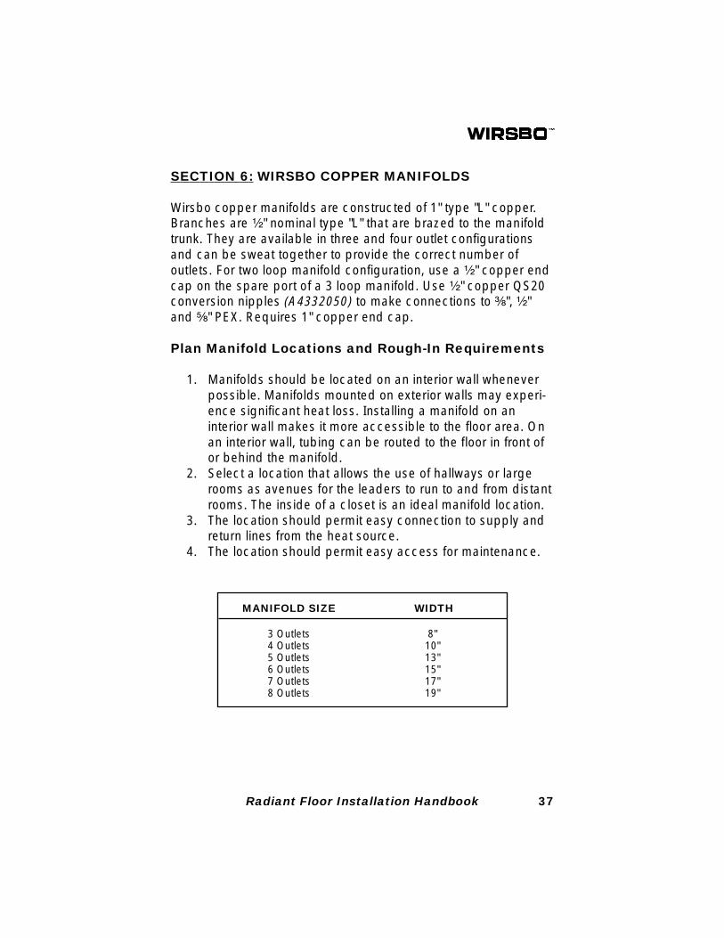
MANIFOLD SIZE WIDTH
3 Outlets 8"4 Outlets 10"5 Outlets 13"6 Outlets 15"7 Outlets 17"8 Outlets 19"
SECTION 6: WIRSBO COPPER MANIFOLDS
Wirsbo copper manifolds are constructed of 1" type "L" copper.Branches are ¹⁄₂" nominal type "L" that are brazed to the manifoldtrunk. They are available in three and four outlet configurationsand can be sweat together to provide the correct number ofoutlets. For two loop manifold configuration, use a ¹⁄₂" copper endcap on the spare port of a 3 loop manifold. Use ¹⁄₂" copper QS20conversion nipples (A4332050) to make connections to ³⁄₈", ¹⁄₂"and ⁵⁄₈" PEX. Requires 1" copper end cap.
Plan Manifold Locations and Rough-In Requirements
1. Manifolds should be located on an interior wall wheneverpossible. Manifolds mounted on exterior walls may experi-ence significant heat loss. Installing a manifold on aninterior wall makes it more accessible to the floor area. Onan interior wall, tubing can be routed to the floor in front ofor behind the manifold.
2. Select a location that allows the use of hallways or largerooms as avenues for the leaders to run to and from distantrooms. The inside of a closet is an ideal manifold location.
3. The location should permit easy connection to supply andreturn lines from the heat source.
4. The location should permit easy access for maintenance.
38 Radiant Floor Installation Handbook
1
1
5A
5B
5C
47
3
4
7
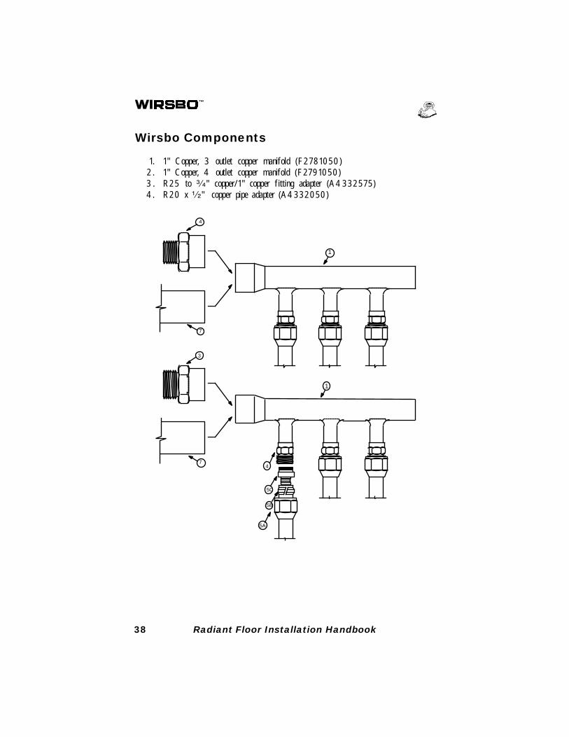
Wirsbo Components
1. 1" Copper, 3 outlet copper manifold (F2781050)2 . 1" Copper, 4 outlet copper manifold (F2791050)3 . R25 to ³⁄₄" copper/1" copper fitting adapter (A4332575)4. R20 x ¹⁄₂" copper pipe adapter (A4332050)
39Radiant Floor Installation Handbook
2
2
6
6
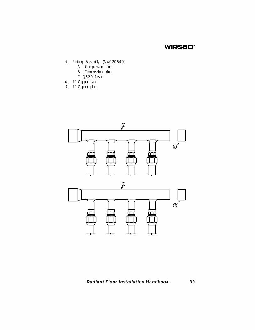
5 . Fitt ing Assembly (A4020500)A. Compression nutB. Compression ringC. QS20 Insert
6 . 1" Copper cap7 . 1" Copper pipe
40 Radiant Floor Installation Handbook
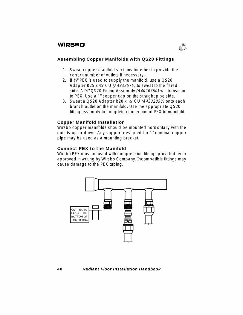
Assembling Copper Manifolds with QS20 Fittings
1. Sweat copper manifold sections together to provide thecorrect number of outlets if necessary.
2. If ³⁄₄" PEX is used to supply the manifold, use a QS20Adapter R25 x ³⁄₄" CU (A4332575) to sweat to the flaredside. A ³⁄₄" QS20 Fitting Assembly (A4020750) will transitionto PEX. Use a 1" copper cap on the straight pipe side.
3. Sweat a QS20 Adapter R20 x ¹⁄₂" CU (A4332050) onto eachbranch outlet on the manifold. Use the appropriate QS20fitting assembly to complete connection of PEX to manifold.
Copper Manifold InstallationWirsbo copper manifolds should be mounted horizontally with theoutlets up or down. Any support designed for 1" nominal copperpipe may be used as a mounting bracket.
Connect PEX to the ManifoldWirsbo PEX must be used with compression fittings provided by orapproved in writing by Wirsbo Company. Incompatible fittings maycause damage to the PEX tubing.
CUT PEX TOREACH THEBOTTOM OFTHE FITTING
41Radiant Floor Installation Handbook
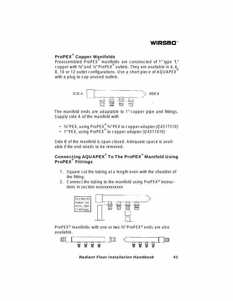
ProPEX® Copper Manifolds
Preassembled ProPEX® manifolds are constructed of 1" type "L"
copper with ³⁄₈" and ¹⁄₂" ProPEX® outlets. They are available in 4, 6,
8, 10 or 12 outlet configurations. Use a short piece of AQUAPEX®
with a plug to cap unused outlets.
The manifold ends are adaptable to 1" copper pipe and fittings.Supply side A of the manifold with
• ³⁄₄" PEX, using ProPEX® ³⁄₄" PEX to copper adapter (Q4517510)
• 1" PEX, using ProPEX® to copper adapter (Q4511010)
Side B of the manifold is spun closed. Adequate space is avail-able if the end needs to be removed.
Connecting AQUAPEX® To The ProPEX
® Manifold Using
ProPEX® Fittings
1. Square cut the tubing at a length even with the shoulder ofthe fitting.
2. Connect the tubing to the manifold using ProPEX® instruc-tions in section xxxxxxxxxxxxx
ProPEX® manifolds with one or two ³⁄₄" ProPEX® ends are alsoavailable.
42 Radiant Floor Installation Handbook
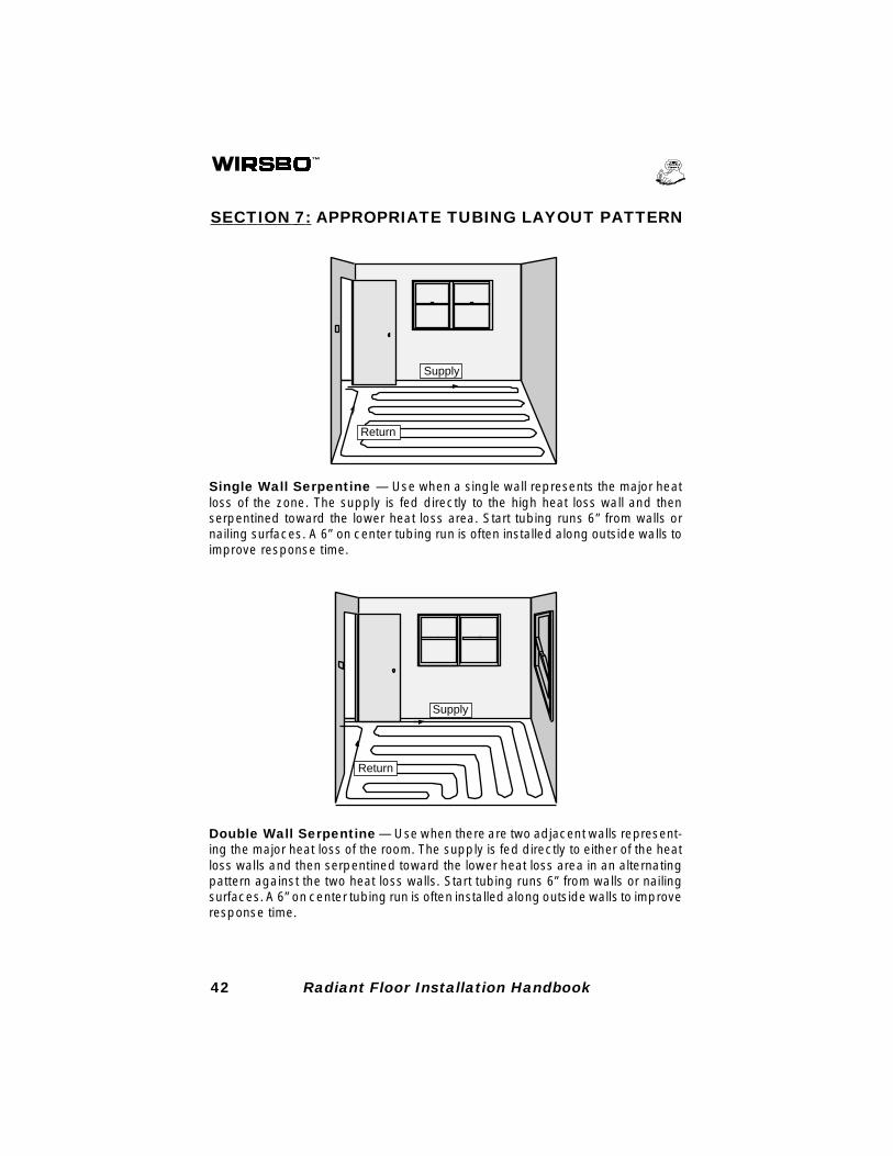
SECTION 7: APPROPRIATE TUBING LAYOUT PATTERN
Single Wall Serpentine — Use when a single wall represents the major heatloss of the zone. The supply is fed directly to the high heat loss wall and thenserpentined toward the lower heat loss area. Start tubing runs 6” from walls ornailing surfaces. A 6” on center tubing run is often installed along outside walls toimprove response time.
Double Wall Serpentine — Use when there are two adjacent walls represent-ing the major heat loss of the room. The supply is fed directly to either of the heatloss walls and then serpentined toward the lower heat loss area in an alternatingpattern against the two heat loss walls. Start tubing runs 6” from walls or nailingsurfaces. A 6” on center tubing run is often installed along outside walls to improveresponse time.
Return
Supply
Return
Supply
43Radiant Floor Installation Handbook
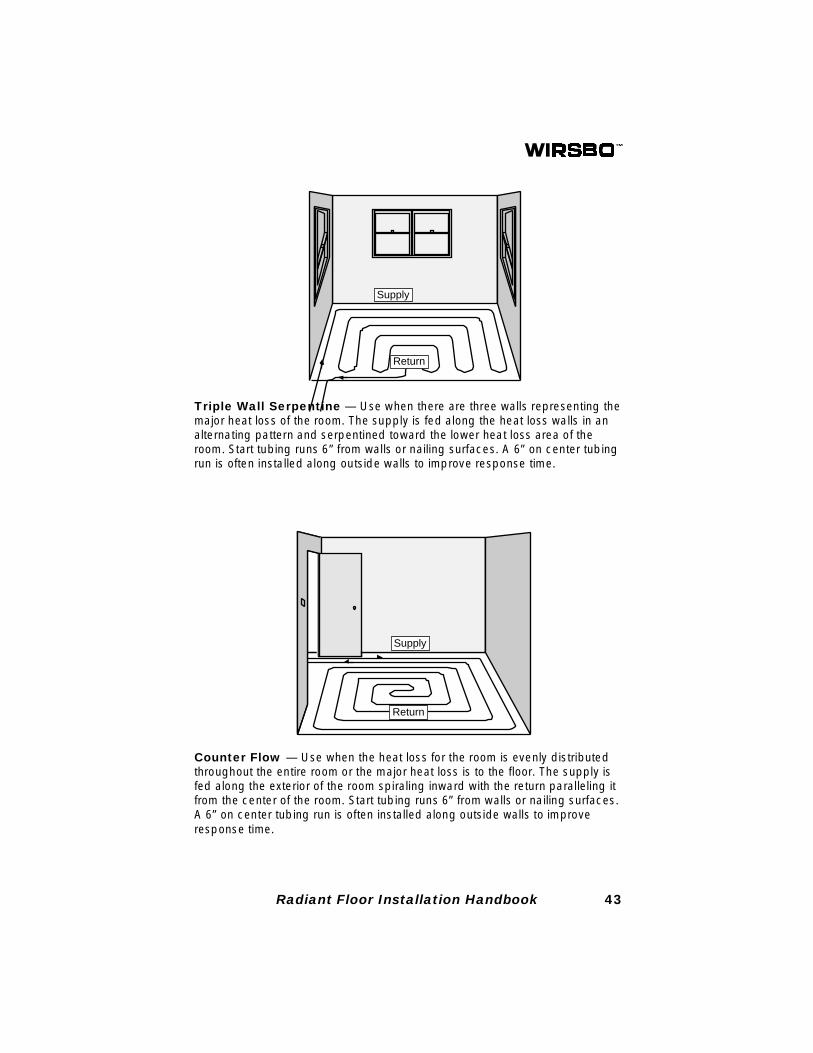
Counter Flow — Use when the heat loss for the room is evenly distributedthroughout the entire room or the major heat loss is to the floor. The supply isfed along the exterior of the room spiraling inward with the return paralleling itfrom the center of the room. Start tubing runs 6” from walls or nailing surfaces.A 6” on center tubing run is often installed along outside walls to improveresponse time.
Triple Wall Serpentine — Use when there are three walls representing themajor heat loss of the room. The supply is fed along the heat loss walls in analternating pattern and serpentined toward the lower heat loss area of theroom. Start tubing runs 6” from walls or nailing surfaces. A 6” on center tubingrun is often installed along outside walls to improve response time.
Supply
Return
Supply
Return
44 Radiant Floor Installation Handbook
SECTION 8: FLOOR/CEILING CONSTRUCTIONMETHODS
Wirsbo radiant floor tubing may be installed in virtually any typeof floor construction. The method of installation varies with thebasic structure of the floor. For the two basic types of floor con-struction, slab on grade and suspended, there are several differ-ent variations of installation. The following pages contain detailedexamples of different construction techniques. It is the responsi-bility of the contractor to assure compliance with local buildingcodes.
(A) Wirsbo PEX in a Slab or Overpour
Structural Factors - Minimum cover for tubing is detailed inthe local building codes. Generally, a minimum of 1¹⁄₂" of con-crete must be poured over the tubing when the slab is exposedto the earth or weather (UBC). When the slab is not exposed tothe earth or weather, a ³⁄₄" concrete pour over the tubing isgenerally acceptable (UBC). Other types of slab constructions(e.g., pre-stressed concrete planking or posttensioned concreteslabs) may have different requirements.
See Chapter 9 of the Wirsbo Complete Design AssistanceManual (CDAM) and check local building codes for additionalinformation.
Joints in Concrete - Concrete slabs often require construc-tion joints, control joints or expansion joints. Details for thesejoints must be specified on the plan. Provisions must be made tocontrol shear forces at the joints and eliminate damage to thetubing.
Construction Joints – Construction joints separate two poursof a slab completed at different times. Because it is difficult toconstruct a large slab in one pour, a bulkhead is installed tocontain sections of the slab until the next phase is poured. It maybe convenient to install the tubing in an area just before the slabis poured. That makes it easier to move concrete equipment from
45Radiant Floor Installation Handbook
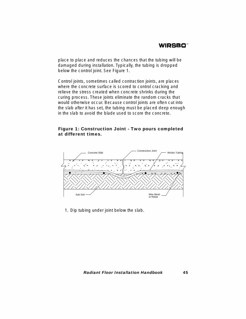
place to place and reduces the chances that the tubing will bedamaged during installation. Typically, the tubing is droppedbelow the control joint. See Figure 1.
Control joints, sometimes called contraction joints, are placeswhere the concrete surface is scored to control cracking andrelieve the stress created when concrete shrinks during thecuring process. These joints eliminate the random cracks thatwould otherwise occur. Because control joints are often cut intothe slab after it has set, the tubing must be placed deep enoughin the slab to avoid the blade used to score the concrete.
1. Dip tubing under joint below the slab.
Concrete SlabConstruction Joint
Sub Soil
Wirsbo Tubing
Wire Meshor Rebar
Figure 1: Construction Joint - Two pours completedat different times.
46 Radiant Floor Installation Handbook
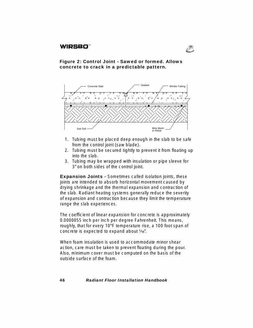
1. Tubing must be placed deep enough in the slab to be safefrom the control joint (saw blade).
2. Tubing must be secured tightly to prevent it from floating upinto the slab.
3. Tubing may be wrapped with insulation or pipe sleeve for3" on both sides of the control joint.
Concrete Slab Sealant
Sub Soil
Wirsbo Tubing
Wire Meshor Rebar
Figure 2: Control Joint - Sawed or formed. Allowsconcrete to crack in a predictable pattern.
Expansion Joints – Sometimes called isolation joints, thesejoints are intended to absorb horizontal movement caused bydrying shrinkage and the thermal expansion and contraction ofthe slab. Radiant heating systems generally reduce the severityof expansion and contraction because they limit the temperaturerange the slab experiences.
The coefficient of linear expansion for concrete is approximately0.0000055 inch per inch per degree Fahrenheit. This means,roughly, that for every 10°F temperature rise, a 100 foot span ofconcrete is expected to expand about ¹⁄₁₆".
When foam insulation is used to accommodate minor shearaction, care must be taken to prevent floating during the pour.Also, minimum cover must be computed on the basis of theoutside surface of the foam.
47Radiant Floor Installation Handbook
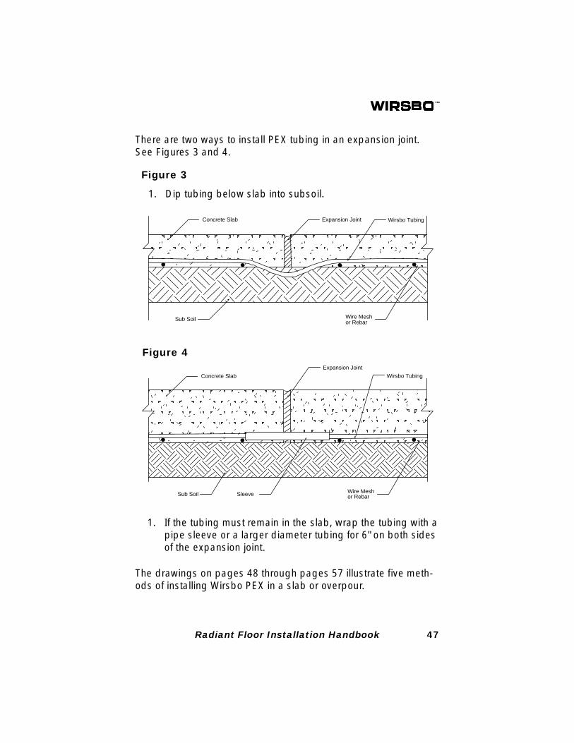
There are two ways to install PEX tubing in an expansion joint.See Figures 3 and 4.
Figure 3
1. Dip tubing below slab into subsoil.
Concrete Slab Expansion Joint
Sub Soil
Wirsbo Tubing
Wire Meshor Rebar
Concrete Slab
Expansion Joint
Sub Soil
Wirsbo Tubing
Wire Meshor RebarSleeve
1. If the tubing must remain in the slab, wrap the tubing with apipe sleeve or a larger diameter tubing for 6" on both sidesof the expansion joint.
Figure 4
The drawings on pages 48 through pages 57 illustrate five meth-ods of installing Wirsbo PEX in a slab or overpour.

48 Radiant Floor Installation Handbook
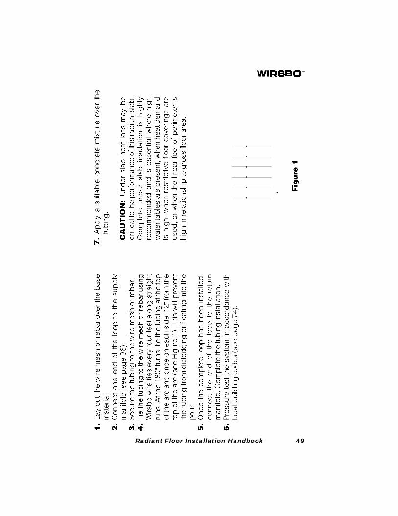
49Radiant Floor Installation Handbook

50 Radiant Floor Installation Handbook
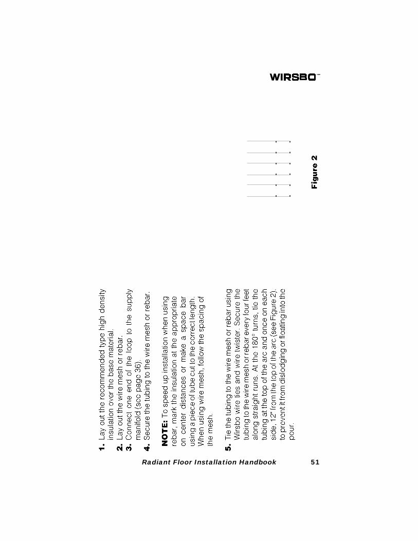
51Radiant Floor Installation Handbook

52 Radiant Floor Installation Handbook
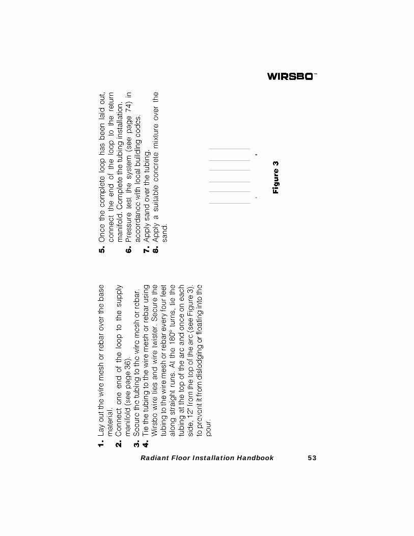
53Radiant Floor Installation Handbook

54 Radiant Floor Installation Handbook
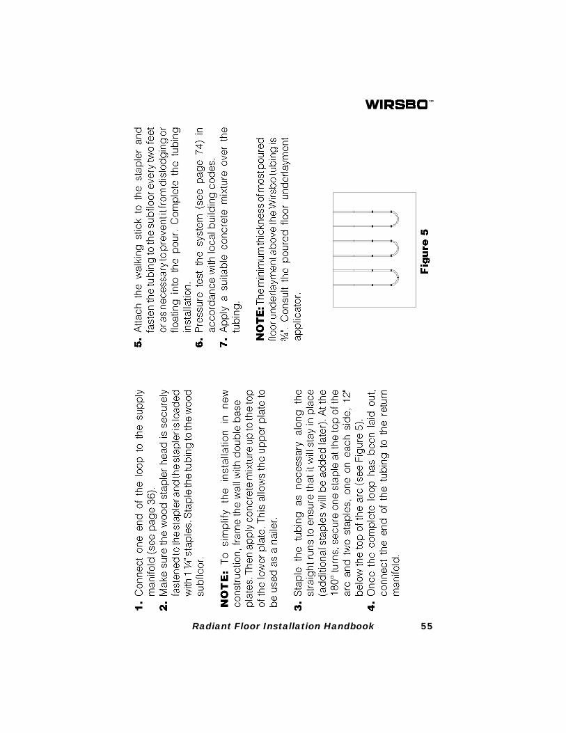
55Radiant Floor Installation Handbook

56 Radiant Floor Installation Handbook
57Radiant Floor Installation Handbook
58 Radiant Floor Installation Handbook
Drawing A: Side View Of Joist
1/3 OF THE WAY DOWN
JOIST
4" - 6"
1-1/2" HOLES
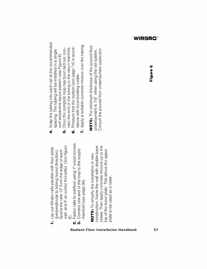
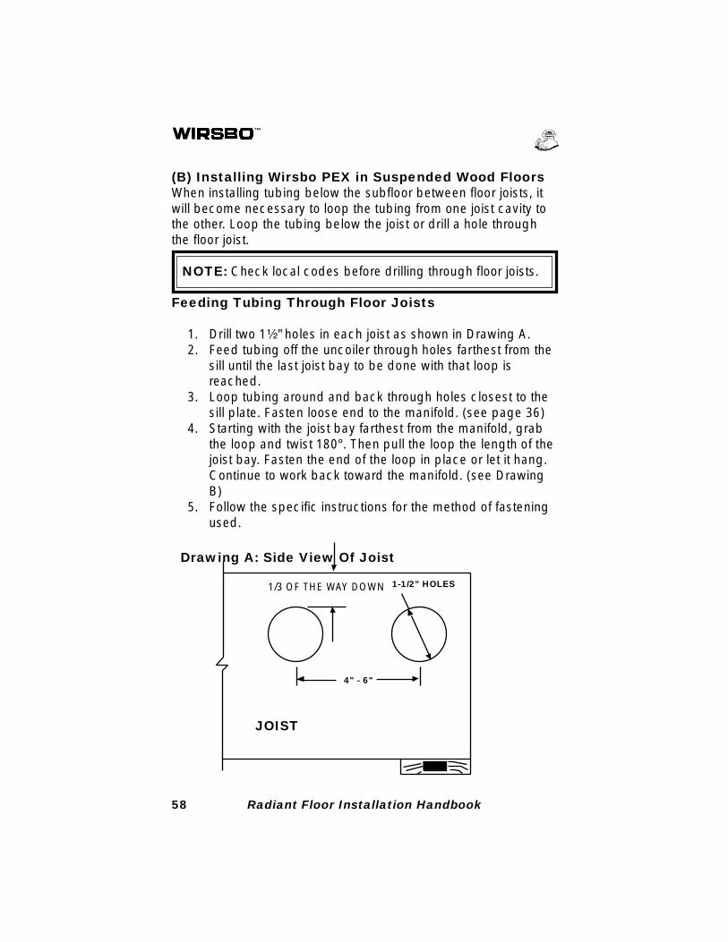
(B) Installing Wirsbo PEX in Suspended Wood FloorsWhen installing tubing below the subfloor between floor joists, itwill become necessary to loop the tubing from one joist cavity tothe other. Loop the tubing below the joist or drill a hole throughthe floor joist.
NOTE: Check local codes before drilling through floor joists.
Feeding Tubing Through Floor Joists
1. Drill two 1¹⁄₂" holes in each joist as shown in Drawing A.2. Feed tubing off the uncoiler through holes farthest from the
sill until the last joist bay to be done with that loop isreached.
3. Loop tubing around and back through holes closest to thesill plate. Fasten loose end to the manifold. (see page 36)
4. Starting with the joist bay farthest from the manifold, grabthe loop and twist 180°. Then pull the loop the length of thejoist bay. Fasten the end of the loop in place or let it hang.Continue to work back toward the manifold. (see DrawingB)
5. Follow the specific instructions for the method of fasteningused.
59Radiant Floor Installation Handbook
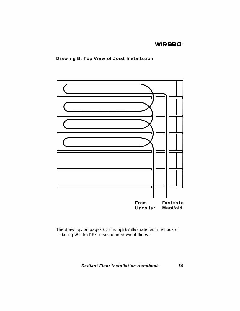
Drawing B: Top View of Joist Installation
FromUncoiler
Fasten toManifold
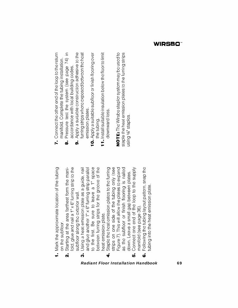
The drawings on pages 60 through 67 illustrate four methods ofinstalling Wirsbo PEX in suspended wood floors.

60 Radiant Floor Installation Handbook
61Radiant Floor Installation Handbook

62 Radiant Floor Installation Handbook
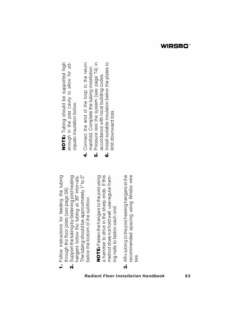
63Radiant Floor Installation Handbook

64 Radiant Floor Installation Handbook
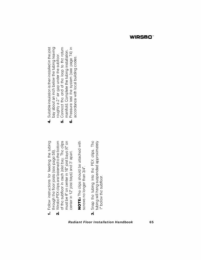
65Radiant Floor Installation Handbook

66 Radiant Floor Installation Handbook
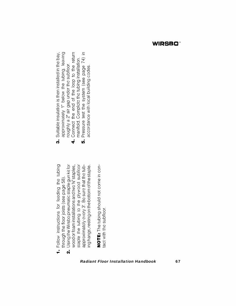
67Radiant Floor Installation Handbook

68 Radiant Floor Installation Handbook
69Radiant Floor Installation Handbook
70 Radiant Floor Installation Handbook
71Radiant Floor Installation Handbook
72 Radiant Floor Installation Handbook
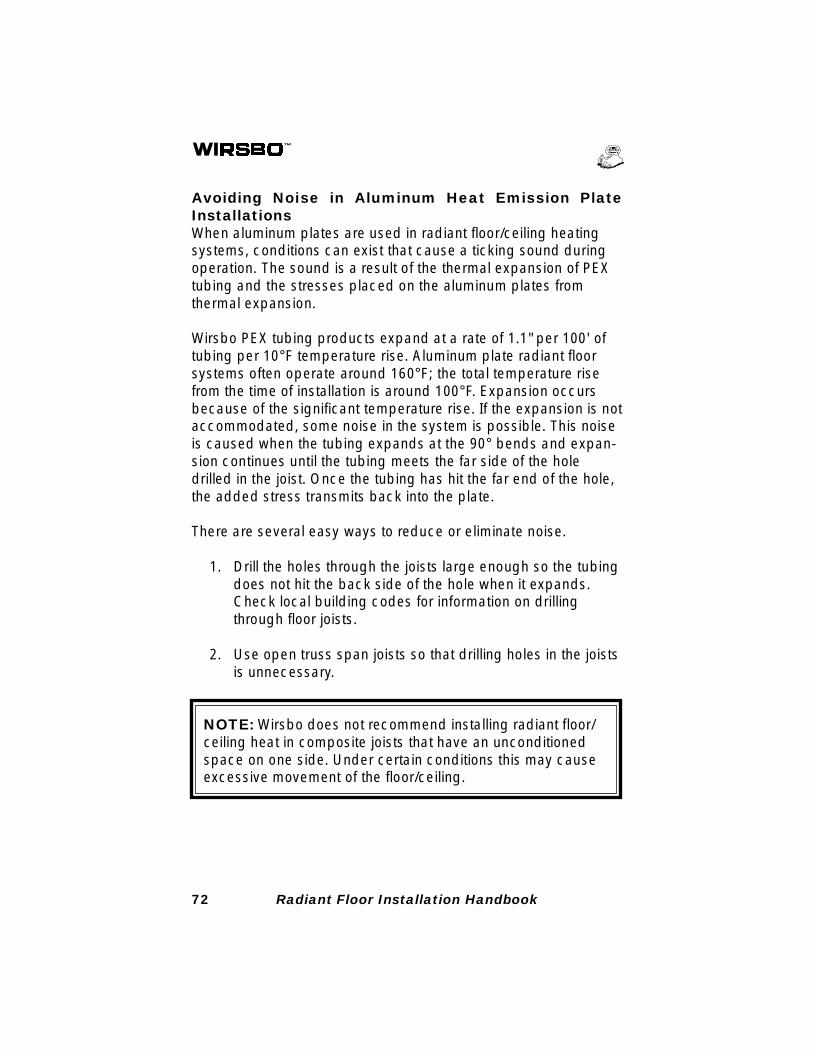
Avoiding Noise in Aluminum Heat Emission PlateInstallationsWhen aluminum plates are used in radiant floor/ceiling heatingsystems, conditions can exist that cause a ticking sound duringoperation. The sound is a result of the thermal expansion of PEXtubing and the stresses placed on the aluminum plates fromthermal expansion.
Wirsbo PEX tubing products expand at a rate of 1.1" per 100' oftubing per 10°F temperature rise. Aluminum plate radiant floorsystems often operate around 160°F; the total temperature risefrom the time of installation is around 100°F. Expansion occursbecause of the significant temperature rise. If the expansion is notaccommodated, some noise in the system is possible. This noiseis caused when the tubing expands at the 90° bends and expan-sion continues until the tubing meets the far side of the holedrilled in the joist. Once the tubing has hit the far end of the hole,the added stress transmits back into the plate.
There are several easy ways to reduce or eliminate noise.
1. Drill the holes through the joists large enough so the tubingdoes not hit the back side of the hole when it expands.Check local building codes for information on drillingthrough floor joists.
2. Use open truss span joists so that drilling holes in the joistsis unnecessary.
NOTE: Wirsbo does not recommend installing radiant floor/ceiling heat in composite joists that have an unconditionedspace on one side. Under certain conditions this may causeexcessive movement of the floor/ceiling.
73Radiant Floor Installation Handbook
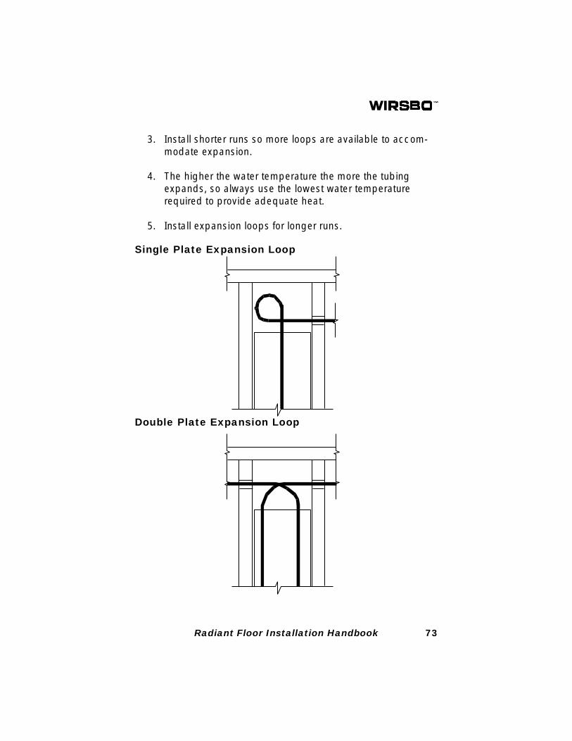
Single Plate Expansion Loop
Double Plate Expansion Loop
3. Install shorter runs so more loops are available to accom-modate expansion.
4. The higher the water temperature the more the tubingexpands, so always use the lowest water temperaturerequired to provide adequate heat.
5. Install expansion loops for longer runs.
74 Radiant Floor Installation Handbook
SECTION 9: SYSTEM START-UP
Pressure Testing the SystemBefore the tubing is covered, the system must be pressuretested. Air or water may be used as a test medium. Each mani-fold may be tested separately or, depending upon the construc-tion schedule, the entire system may be tested at one time. Thefollowing is a recommended procedure for pressure testing.
1. Be sure all connections are properly sealed using thesupplied gaskets.
2. On end cap with vent, remove air vent and drain cock andreplace with proper sized plugs.
3. Install the Wirsbo Pressure Test Kit (E6122000) or suitablepressure test kit onto the system.
4. Pressurize the system with water or air to 60 psi. Thesystem should maintain the 60 psi for a minimum of 24hours.
5. Depending on the circumstances of the installation, thePEX tubing may expand under pressure and require a onetime addition of water or air to offset the tubing expansion.
Maintain pressure on the system during the slab pour or whenfinished flooring is being installed. This simplifies leak detection ifthe tubing is damaged during the pour or installation.
NOTE: The manifold internal valving is made up of flow valvesthat are not designed to hold high pressure. Pressure testingagainst these valves may result in some leakage and maycompromise the test. Use appropriate end caps or plugs tofurther seal the system, as necessary.
The testing procedure detailed above is a recommendation fromthe Wirsbo Company. Check local building codes for complianceor additional test requirements.
Filling the System with WaterOnce the entire system has been properly pressure tested, use
75Radiant Floor Installation Handbook
the following procedure to fill it with water:
1. Connect the system (at a fill point) to a water source.2. Open all valves in the system. Be sure that all manual
valves on the return manifolds are fully open by turningthem counter-clockwise.
3. Open the in-line fill valve to begin filling the system withwater. As the system fills and pressure builds, open thevent at the highest point available.
Purging Air from the SystemIn order for the system to operate properly, all the air must bepurged from the system. There are several methods to purge airfrom the system. One manifold at a time simplifies the process.
For Valved Manifold Assemblies
1. Close all the isolation valves for each supply and returnmanifold.
2. One manifold at a time, attach one end of a service hose(female garden hose connector) directly to the boiler drainon the end cap and place the other end into a pail of water.Make sure the boiler drain is completely open and the hoseis completely submerged in the bucket.
3. Close each manifold balancing valve (turn clockwise).4. Start the circulator that services that manifold.
NOTE: Domestic water pressure or other means may benecessary to purge trapped air from the system.
5. Open the isolation valve to the supply manifold.6. Open one manifold balancing valve. Allow water to circu-
late until no air is discharged into the bucket. Close allbalancing valves.
7. Repeat this procedure for each balancing valve (eachloop).
8. When all the loops on the manifold are completely purged,close the isolation valve to the supply manifold.
9. Repeat the process for each manifold.
76 Radiant Floor Installation Handbook
= Balance Setting
For Valveless Manifold Assemblies
1. Close all the isolation valves for each supply and returnmanifold.
2. One manifold at a time, attach one end of a service hose(female garden hose connector) directly to the boiler drainand place the other end into a pail of water. Make sure theboiler drain is completely open and the hose is completelysubmerged in the bucket.
3. Start the circulator that services that manifold.
NOTE: Domestic water pressure or other means may benecessary to purge entrained air from system.
4. Open the isolation valve to the supply manifold. Allow waterto circulate until no air is discharged into the bucket.
5. Close the isolation valve to the supply manifold.6. Repeat the process for each manifold.
Initial Balancing of Manifold LoopsWhen it is not possible to design your system using equal looplengths (loop lengths within three percent of each other), then thesystem must be balanced in order to ensure adequate flow toeach loop on a manifold. Wirsbo recommends that the systemsbe designed with telestats controlling the on/off flow for eachloop, in response to the appropriate zone thermostat's call forheat. In addition, zone valves can be effectively used to controlthe flow to an entire manifold in response to a call for heat fromthe zone thermostat.
NOTE: The balance setting is the number of half turns fromclosed.
Initial Flow Balancing Calculations for Wirsbo Manifolds(A2513220), (A2533220) and (A2553220).
Length of tubing in loop to be balanced x 4Length of the longest loop on the manifold
77Radiant Floor Installation Handbook
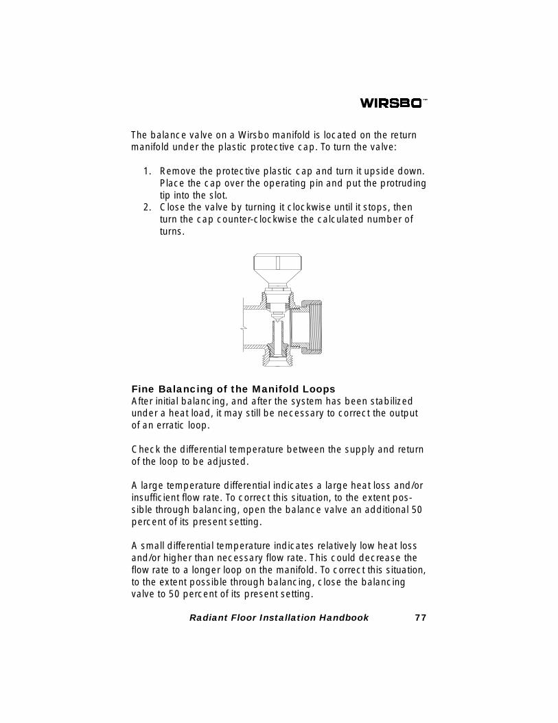
The balance valve on a Wirsbo manifold is located on the returnmanifold under the plastic protective cap. To turn the valve:
1. Remove the protective plastic cap and turn it upside down.Place the cap over the operating pin and put the protrudingtip into the slot.
2. Close the valve by turning it clockwise until it stops, thenturn the cap counter-clockwise the calculated number ofturns.
Fine Balancing of the Manifold LoopsAfter initial balancing, and after the system has been stabilizedunder a heat load, it may still be necessary to correct the outputof an erratic loop.
Check the differential temperature between the supply and returnof the loop to be adjusted.
A large temperature differential indicates a large heat loss and/orinsufficient flow rate. To correct this situation, to the extent pos-sible through balancing, open the balance valve an additional 50percent of its present setting.
A small differential temperature indicates relatively low heat lossand/or higher than necessary flow rate. This could decrease theflow rate to a longer loop on the manifold. To correct this situation,to the extent possible through balancing, close the balancingvalve to 50 percent of its present setting.
78 Radiant Floor Installation Handbook
SECTION 10: ELECTRICAL CONTROLS
Mounting the ThermostatsEach zone is controlled by a thermostat. The thermostat shouldbe located:
1. In an area that experiences an average ambient tempera-ture of the zone. Never locate a thermostat on an exteriorwall or in close proximity to an exterior door or window.Avoid locations that are exposed to direct sunlight, abnor-mal drafts or other factors that could result in erroneoustemperature readings.
2. The thermostat should be mounted 60" above the finishedfloor.
The Wirsbo Zone Control ModuleThe Wirsbo Zone Control Module (A2553220) is a printed circuitcontrol and diagnostic device that is designed to be used withWirsbo thermostats and four wire telestats or zone valves. Themodule provides: connection to the power supply transformer, theinterconnections between the individual thermostats and theirrespective telestats or zone valves, and the buss connectionbetween all end switches. The control module is available in boththree and four zone configurations and may be ganged togetherwith other modules to provide connections for up to 10 zones atany one location. The modules are internally fused for protectionfrom overcurrent or direct shorts at the telestats and thermostats.
The end switch circuit is not protected from overcurrent or directshorts and should have a 2 amp (maximum) fuse installed.
Diagnostic FeaturesThe Wirsbo Control Modules are equipped with light emittingdiodes (LEDs) to indicate various functions of control. A greenLED indicates that power is supplied to the module. Yellow LEDsindicate which zone(s) are calling for heat. Red LEDs indicatewhich end switches are closed and signalling the boiler or circu-lator pump to engage.
79Radiant Floor Installation Handbook
FIGURE 1
Compatible ComponentsThe Control Modules are designed to be used with DT10 thermo-stats (A3030011), DT20 thermostat (A3030021), T86H thermo-stats (A3010086), 4 wire motorized valve actuators (A3020522)and 4 wire zone valves (A3070526). The control module is alsodesigned to be wired with Wirsbo's weather responsive resetcontrols, the ProMix™ 101 (A3091000 & A3091250) and theDuoMix™ 201 (A3030005).
Mounting InstructionsFor best results, mount the control module in a convenient loca-tion above the telestats using either the double stick tape (pro-vided) or the mounting holes and suitable hardware. Ensure thatthe module will not be exposed to moisture or physical damage.
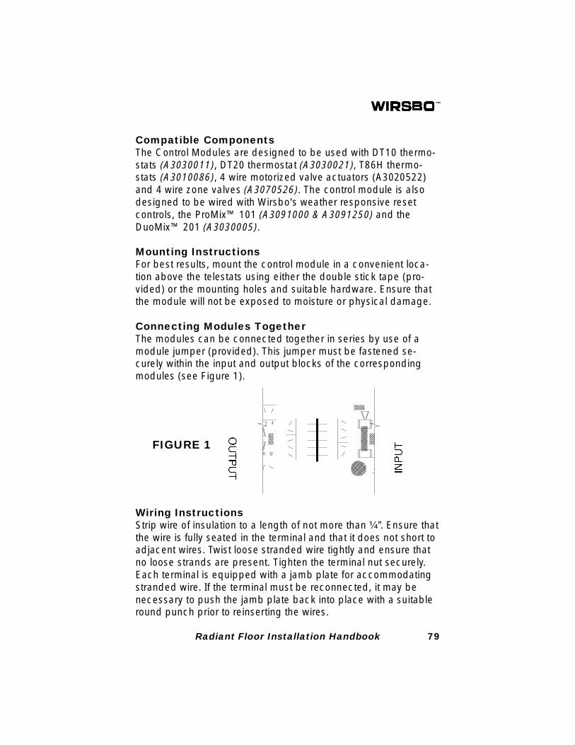
Connecting Modules TogetherThe modules can be connected together in series by use of amodule jumper (provided). This jumper must be fastened se-curely within the input and output blocks of the correspondingmodules (see Figure 1).
Wiring InstructionsStrip wire of insulation to a length of not more than ¹⁄₄". Ensure thatthe wire is fully seated in the terminal and that it does not short toadjacent wires. Twist loose stranded wire tightly and ensure thatno loose strands are present. Tighten the terminal nut securely.Each terminal is equipped with a jamb plate for accommodatingstranded wire. If the terminal must be reconnected, it may benecessary to push the jamb plate back into place with a suitableround punch prior to reinserting the wires.
80 Radiant Floor Installation Handbook
Combining Multiple Telestats or Zone ValvesMultiple telestats or zone valves may be ganged together in thesame telestat block to be controlled by one thermostat. If wiresfrom telestat or zone valves become too bulky to fit in the wiringblock when ganged together, junction the wires prior to connect-ing them to the block.
Fuse ReplacementReplace the fuse as necessary with one of the following:2 amp fuse for 50VA transformer3 amp fuse for 75VA transformer4 amp fuse for 100VA transformer (maximum)
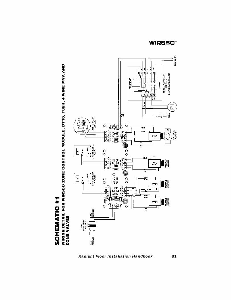
Wiring SchematicThe following schematics provide detailed wiring instructions forcommon control strategies. Refer to the Complete Design Assis-tance Manual (CDAM), Chapter 12, for more wiring schematicsand information.
81Radiant Floor Installation Handbook
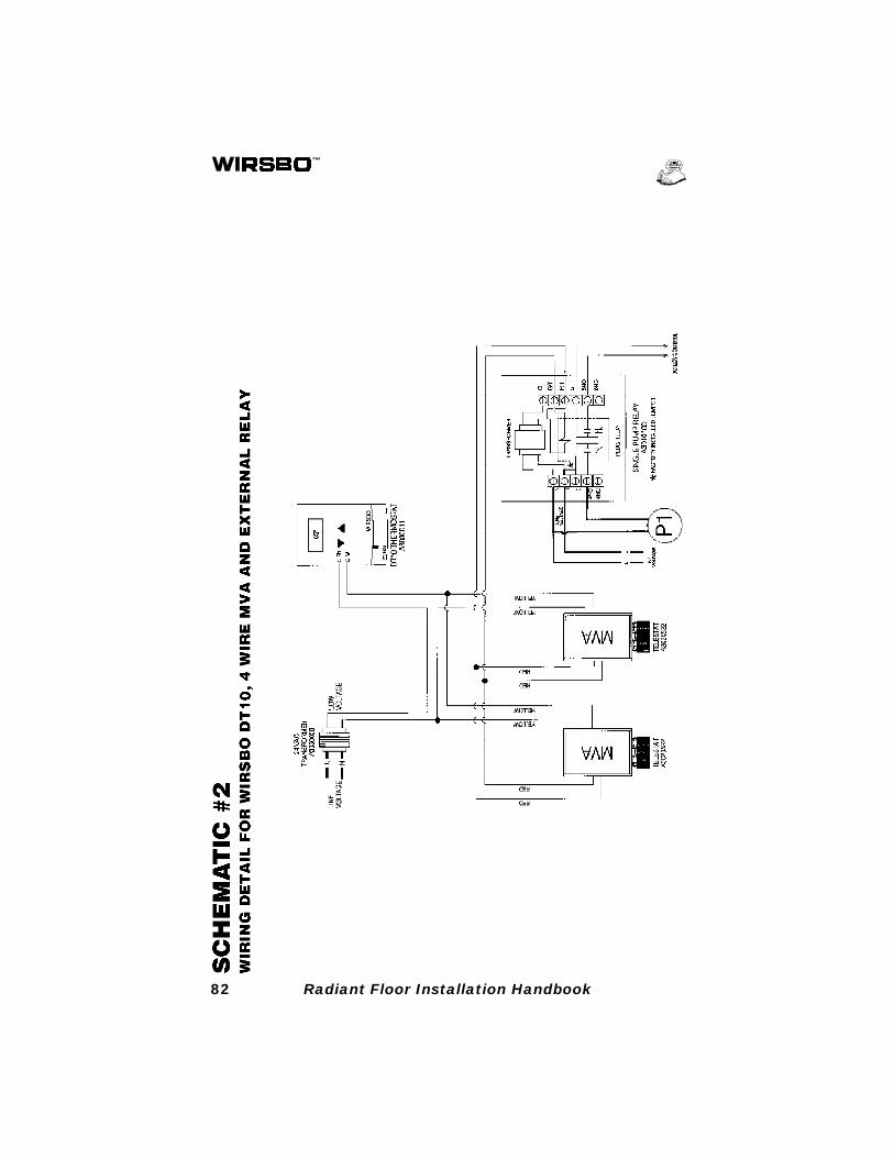
82 Radiant Floor Installation Handbook
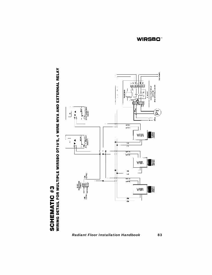
83Radiant Floor Installation Handbook
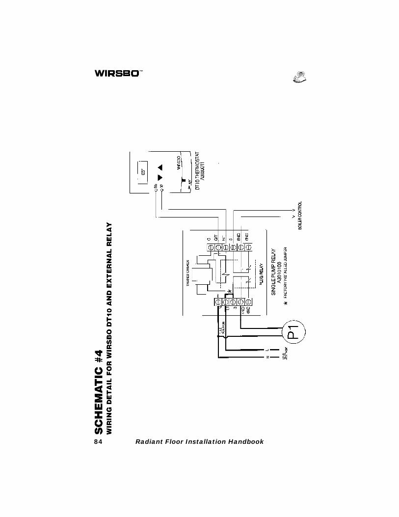
84 Radiant Floor Installation Handbook
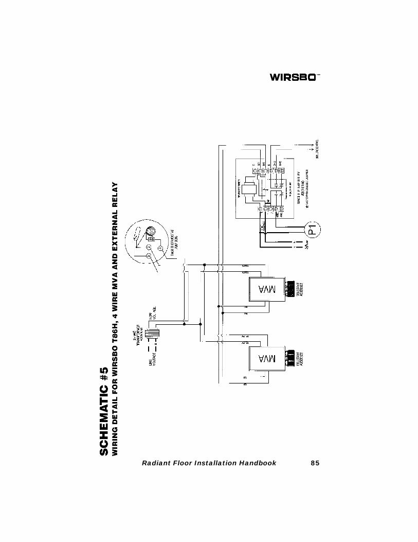
85Radiant Floor Installation Handbook
86 Radiant Floor Installation Handbook
87Radiant Floor Installation Handbook
88 Radiant Floor Installation Handbook
RADIPEX™ SYSTEMS
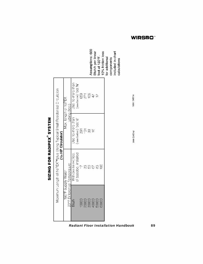
Wirsbo RADIPEX™ is a baseboard and radiator supply systemthat features Wirsbo hePEX™plus tubing. The RADIPEX™ systemis less expensive and easier to install than copper piping. Somecontractors report cutting labor in half by using RADIPEX™instead of copper.
RADIPEX™ is ideal for use with fin tube baseboard, unit heaters,cast iron radiators and panel type radiators.
This section of the Radiant Heating Installation Handbook isintended to educate contractors, architects, engineers andHVAC officials with the products and techniques used to install aRADIPEX™ system.
CodesSince Wirsbo hePEX™plus is used in the RADIPEX™ system, allWirsbo product codes listed on page 4 apply. In addition, WirsbohePEX™plus and RADIPEX™ heating products are approved foruse by ICBO. See ICBO Research Report No. 5143 for allowablevalues or conditions of use concerning material presented in thisdocument.
Working with hePEX™plusSee Section 3: Working with PEX for detailed guidelines to befollowed when using hePEX™plus tubing.
Joints and ConnectionsThe RADIPEX™ system uses Wirsbo QS20 compression andProPEX
® fittings. See page 18 for instructions on how to properly
use Wirsbo QS20 compression fittings and page 23 for installingProPEX
® Fittings. The fittings and components specific to the
RADIPEX™ system are detailed on the following pages.
89Radiant Floor Installation Handbook
90 Radiant Floor Installation Handbook
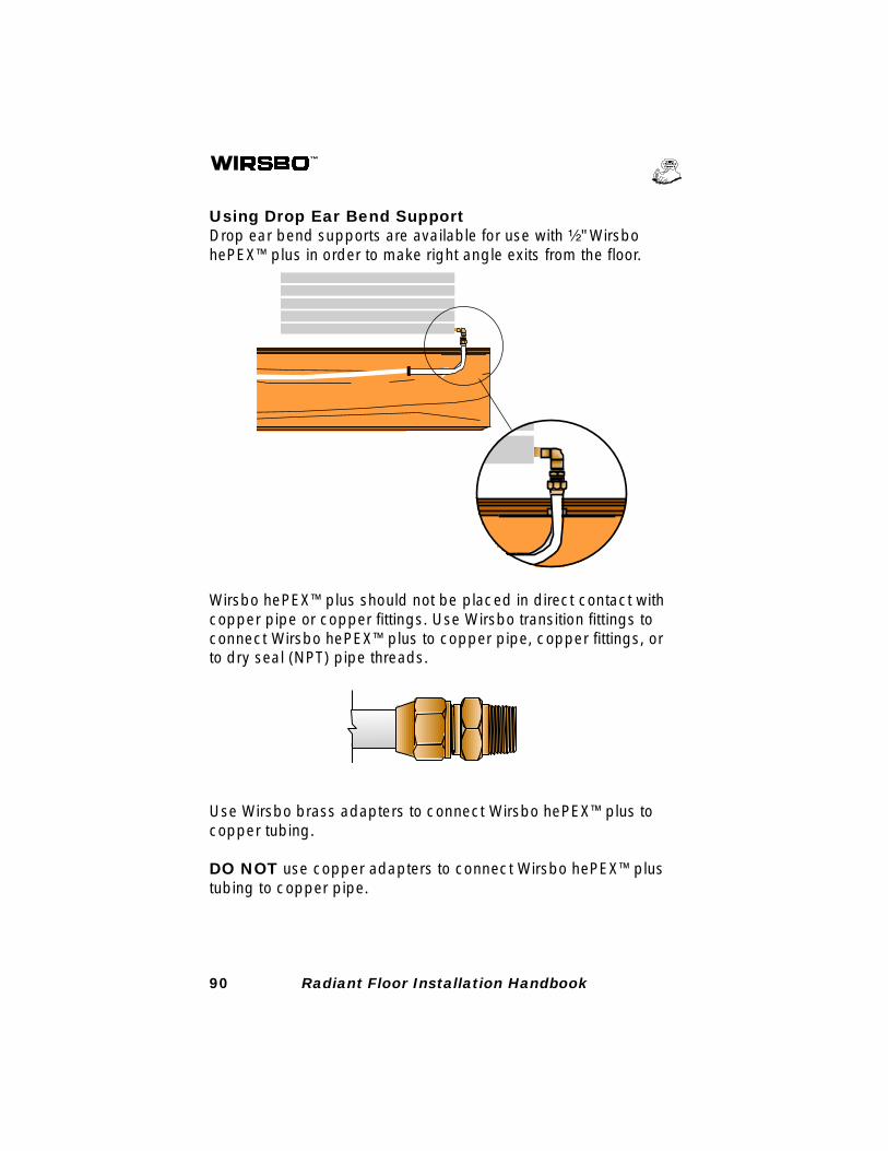
Using Drop Ear Bend SupportDrop ear bend supports are available for use with ¹⁄₂" WirsbohePEX™plus in order to make right angle exits from the floor.
Wirsbo hePEX™plus should not be placed in direct contact withcopper pipe or copper fittings. Use Wirsbo transition fittings toconnect Wirsbo hePEX™plus to copper pipe, copper fittings, orto dry seal (NPT) pipe threads.
Use Wirsbo brass adapters to connect Wirsbo hePEX™plus tocopper tubing.
DO NOT use copper adapters to connect Wirsbo hePEX™plustubing to copper pipe.
91Radiant Floor Installation Handbook
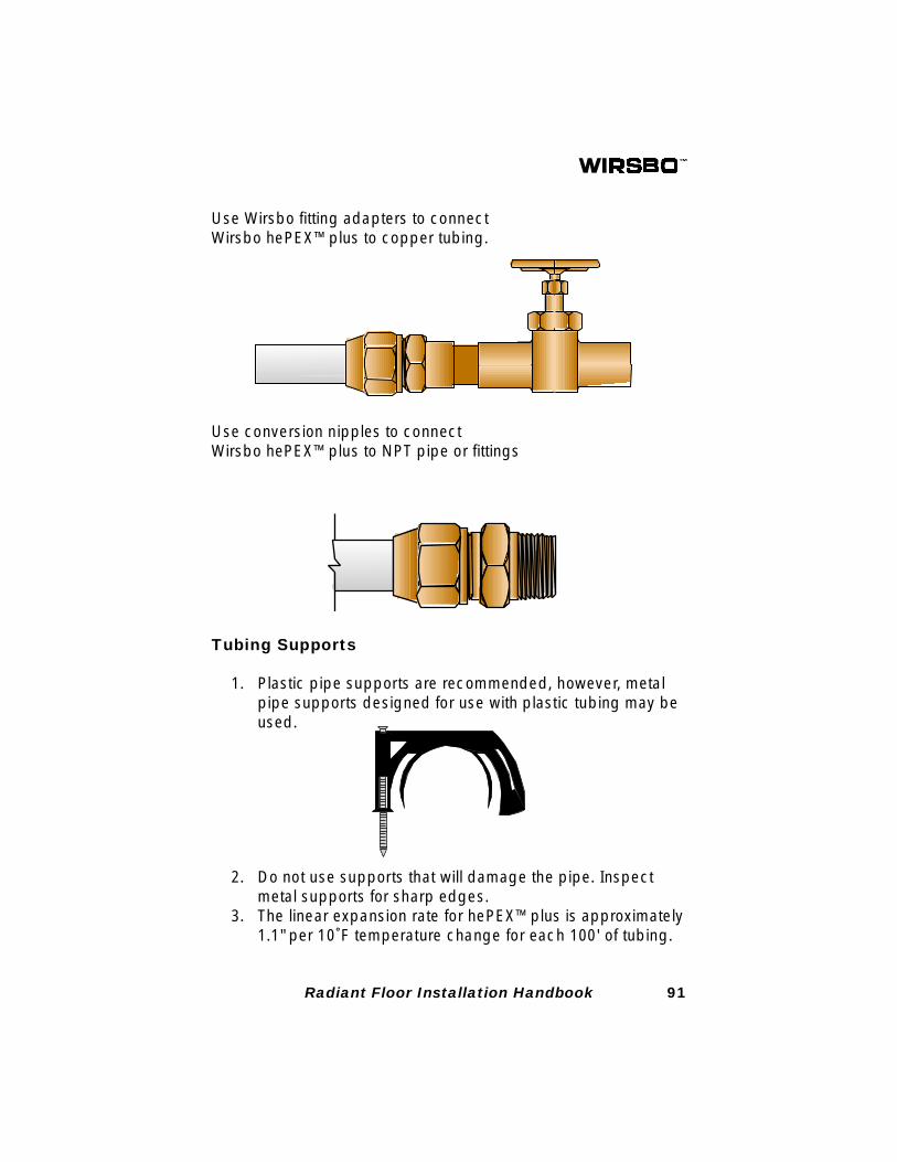
Use Wirsbo fitting adapters to connectWirsbo hePEX™plus to copper tubing.
Use conversion nipples to connectWirsbo hePEX™plus to NPT pipe or fittings
Tubing Supports
1. Plastic pipe supports are recommended, however, metalpipe supports designed for use with plastic tubing may beused.
2. Do not use supports that will damage the pipe. Inspectmetal supports for sharp edges.
3. The linear expansion rate for hePEX™plus is approximately1.1" per 10˚F temperature change for each 100' of tubing.
92 Radiant Floor Installation Handbook
4' - 0"
BEND SUPPORT
BEND SUPPORT
PIPE SUPPORT
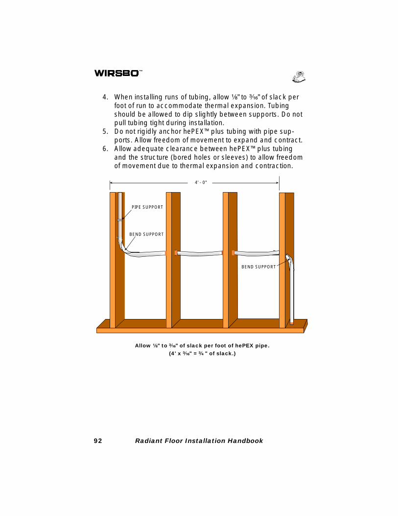
Allow ¹⁄₈" to ³⁄₁₆" of slack per foot of hePEX pipe.(4' x ³⁄₁₆" = ³⁄₄ " of slack.)
4. When installing runs of tubing, allow ¹⁄₈" to ³⁄₁₆" of slack perfoot of run to accommodate thermal expansion. Tubingshould be allowed to dip slightly between supports. Do notpull tubing tight during installation.
5. Do not rigidly anchor hePEX™plus tubing with pipe sup-ports. Allow freedom of movement to expand and contract.
6. Allow adequate clearance between hePEX™plus tubingand the structure (bored holes or sleeves) to allow freedomof movement due to thermal expansion and contraction.
93Radiant Floor Installation Handbook
32"
TUBE SUPPORT
BENDSUPPORT
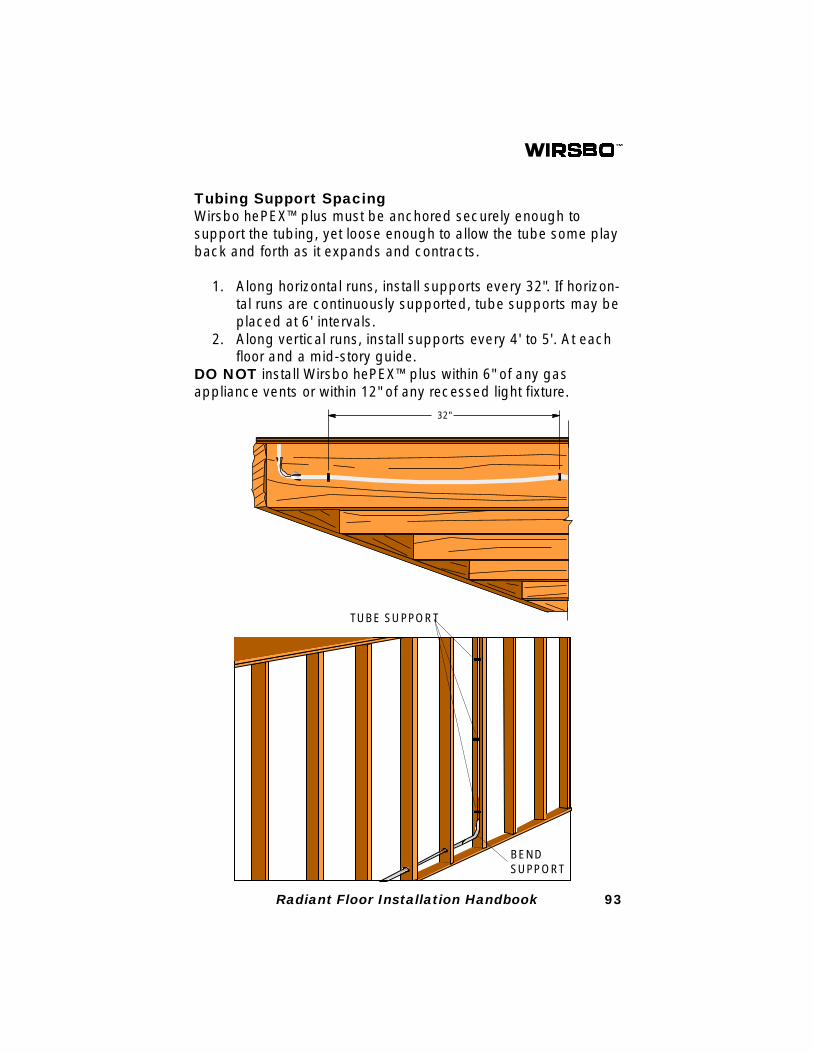
Tubing Support SpacingWirsbo hePEX™plus must be anchored securely enough tosupport the tubing, yet loose enough to allow the tube some playback and forth as it expands and contracts.
1. Along horizontal runs, install supports every 32". If horizon-tal runs are continuously supported, tube supports may beplaced at 6' intervals.
2. Along vertical runs, install supports every 4' to 5'. At eachfloor and a mid-story guide.
DO NOT install Wirsbo hePEX™plus within 6" of any gasappliance vents or within 12" of any recessed light fixture.

94 Radiant Floor Installation Handbook
For more detailed information about radiant floor heating systemsincluding installation methods, wiring diagrams, control strategiesand product information, consult the Wirsbo Complete DesignAssistance Manual (CDAM).

95Radiant Floor Installation Handbook

96 Radiant Floor Installation Handbook