Embed Size (px)
Citation preview

ArmorMax® Anchored Reinforced Vegetation System
FOR SLOPE EROSION CONTROL
INSTALLATION AND MAINTENANCE GUIDELINES
Propex Operating Company, LLC – 1100 Market Street, Chattanooga, TN 37402 - p 800 621 1273 - www.propexglobal.com
Thank you for purchasing the ArmorMax® Anchor Reinforced Vegetation System by Propex Operating Company,
LLC (Propex). This document provides installation and maintenance guidelines for ArmorMax used as slope
armoring to increase earthen slope resiliency. ArmorMax provides permanent erosion protection on either the
flood side and/ or protected side of an earthen slope, and consists of two components:
Pyramat® - High Performance Turf Reinforcement Mat (HPTRM)
Percussion Driven Earth Anchors (PDEA)
Temporary securing pins (pins) are used during installation to hold Pyramat in place while installing PDEAs.
Pins also promote vegetation establishment keeping Pyramat in intimate contact with the soil.
ArmorMax is an engineered solution with a unique design for each specific project. While Propex has made
every effort to ensure general validity, this information should not be used for a specific application without
independent professional examination and verification of its suitability, applicability, and accuracy. The
information provided herein is for general information only, and is intended to present installation guidance.
Project specific contract documents take precedence when pin and PDEA placements are different than what
is represented in this document. Depending upon the critical nature of the structure to be armored, work
restrictions may be in place such as limiting work based on growing seasons, weather patterns, etc. Work
should be performed under the provisions set forth for the specific project. Propex Engineering Services is
available for support during installation to consult for solving constructability issues encountered in specific
applications. Please feel free to call our techincal support hotline at (423) 553-2450.
BEFORE INSTALLATION BEGINS
Coordinate with a Propex Representative: A pre-construction meeting is suggested with the construction
team and a representative from Propex. This meeting should be scheduled by the contractor with at least a
two week notice.
Gather the Tools Needed: Tools that you will need to install ArmorMax include a pair of industrial shears to
cut Pyramat, tape measure, percussion hammer (sized appropriately for the PDEAs), ground rod driver
compatible with the percussion hammer, drive steel compatible with the PDEA, setting tool to set and load-
lock the PDEA, and wire cutters to cut the cable tendon of the PDEA. If PDEAs will be load tested during
construction, additional testing equipment may be necessary. Consult the “Anchor Load Test Manual”
from Propex for further guidance. Available for purchase from Propex are drive steel, setting tools, and
wire cutters.
Determine how to Establish Vegetation: The method of vegetation establishment should be determined
prior to the start of installation. Different vegetation establishment methods require different orders of
installation. Refer to Establish Vegetation for further guidance.
Page 2 of 19
Propex Operating Company, 1100 Market Street, Chattanooga, TN 37402 - p 800 621 1273 - www.propexglobal.com
INSTALLATION OF ARMORMAX ON SLOPES
PREPARE THE SITE
It is recommended during all stages of site preparation that disturbed soils remain unprotected for not more
than a single day. Depending on project size this may require progressive site preparation during installation.
1. Grade and compact the area on the slope where ArmorMax will be installed. The slope surface should be
uniform and smooth, having all rocks, clods, vegetation or other objects removed so that during Pyramat
Laydown, Pyramat comes in direct, intimate contact with the slope surface.
2. Prepare the area to be armored with ArmorMax by loosening the topsoil to promote better vegetation
establishment. This may be accomplished with a rotary tiller on slopes 3:1 or flatter. For slopes greater
than 3:1, prepare topsoil in a safe manner.
Figure 1: Crest of Slope (COS) Trench
3. Excavate a Crest of Slope (COS) trench 12 in x 12 in (300 mm x 300 mm) minimum at a distance of 3 ft
(900 mm) from the crest of the slope. (Figure 1).
4. Excavate a Toe of Slope (TOS) trench 12 in x 12 in (300 mm x 300 mm) minimum at a minimum distance
of 5 ft (1.5 m) from the toe of the slope. (Figure 2)
5. If seeding, refer to Vegetation Establishment for additional considerations during site preparation.

Page 3 of 19
Propex Operating Company, 1100 Market Street, Chattanooga, TN 37402 - p 800 621 1273 - www.propexglobal.com
Figure 2: Toe of Slope (TOS) Trench

Page 4 of 19
Propex Operating Company, 1100 Market Street, Chattanooga, TN 37402 - p 800 621 1273 - www.propexglobal.com
INSTALL PDEAs
The ArmorMax PDEA typically consists of a die-cast, aluminum alloy bullet-nose anchor head, a carbon steel
cable tendon, and a load bearing plate fabricated from die-cast zinc and containing an array of openings for
optimal vegetation growth. For quality control purposes and warranty claims, PDEAs should be delivered to the
jobsite fully assembled and ready for installation.
PDEAs are to be installed in locations specified for the project, and are typically installed in conjunction with
Pyramat Laydown. There are several options available from Propex for different types of PDEAs. For optimal
performance with the greatest risk reduction, it is important to select the proper PDEA and perform the
installation in accordance with the pattern designed for required resiliency and long term durability of the
slope.
Figure 3: Type B1 Anchor Detail
Understanding the mechanics behind installing the PDEA component of ArmorMax will result in a quality
ArmorMax installation. The installation of a Type B1 Anchor (Figure 3) is described below. The tools that you
will need are a percussion hammer, a ground rod driver, drive steel compatible with the PDEA, a setting tool,
and wire cutters.
Page 5 of 19
Propex Operating Company, 1100 Market Street, Chattanooga, TN 37402 - p 800 621 1273 - www.propexglobal.com
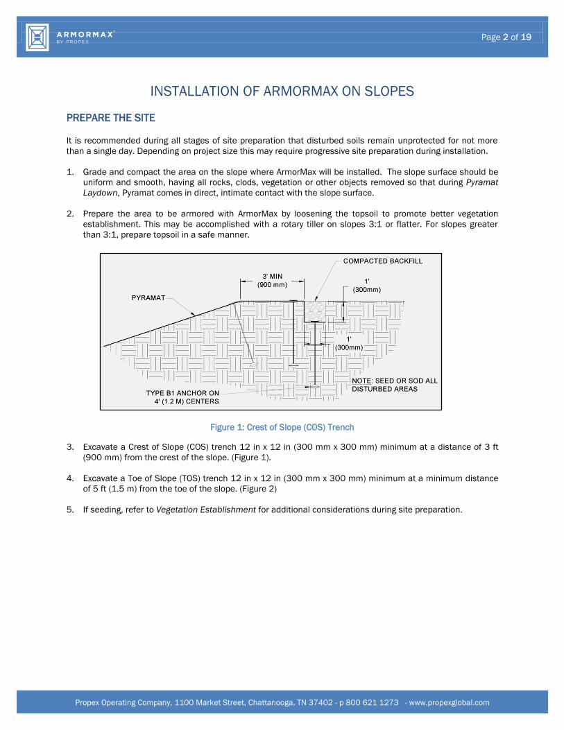
TYPE B1 ANCHOR
1. Insert the tapered end of the drive
steel into the hollow cavity of the
anchor head. Position the anchor
head/ drive steel tip above the ground
at the drive location, being careful to
lay the cable tendon and load bearing
plate (plate) off to the side. (Figure 4
and Figure 5)
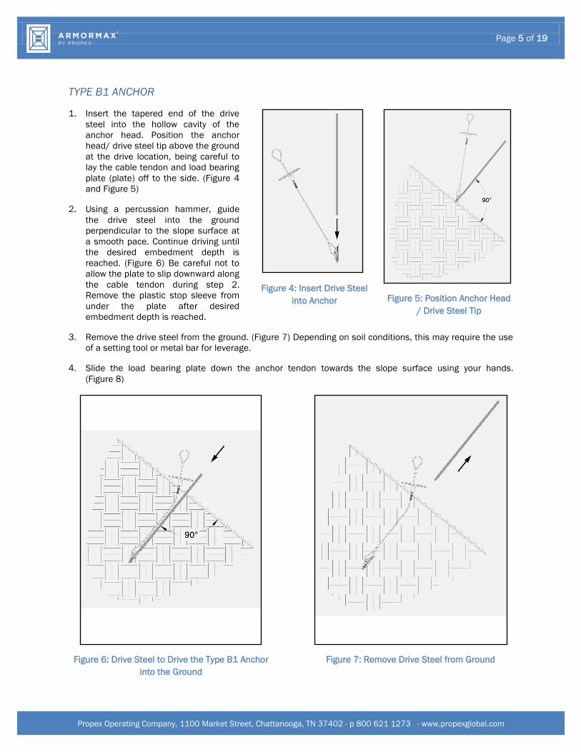
2. Using a percussion hammer, guide
the drive steel into the ground
perpendicular to the slope surface at
a smooth pace. Continue driving until
the desired embedment depth is
reached. (Figure 6) Be careful not to
allow the plate to slip downward along
the cable tendon during step 2.
Remove the plastic stop sleeve from
under the plate after desired
embedment depth is reached.
Figure 4: Insert Drive Steel
into Anchor
Figure 5: Position Anchor Head
/ Drive Steel Tip
3. Remove the drive steel from the ground. (Figure 7) Depending on soil conditions, this may require the use
of a setting tool or metal bar for leverage.
4. Slide the load bearing plate down the anchor tendon towards the slope surface using your hands.
(Figure 8)
Figure 6: Drive Steel to Drive the Type B1 Anchor
into the Ground
Figure 7: Remove Drive Steel from Ground

ArmorMax® Anchored Reinforced Vegetation System
FOR SLOPE EROSION CONTROL
INSTALLATION AND MAINTENANCE GUIDELINES
Propex Operating Company, LLC – 1100 Market Street, Chattanooga, TN 37402 - p 800 621 1273 - www.propexglobal.com
Figure 8: Slide Plate
Figure 9: Use Setting Tool to Set Anchor
5. Once the plate is close to the slope surface, stand on the anchor plate and insert the setting tool into the
loop at the top of the anchor tendon, keeping the anchor tendon perpendicular to the slope surface.
(Figure 9) With gentle force, slowly start to pull upwards - away from the slope surface - causing the anchor
tendon to start to move out of the ground (displace). During this step, the anchor head will turn in the
ground – a process known as “anchor setting”. The change in embedment depth to set a Type B1 Anchor
is approximately 2 inches. When the anchor is set, there will be a noticeable change in the amount of
force needed to displace the anchor any further. This is a good indication that the anchor head is now
perpendicular to the anchor tendon and the anchor is ready to be load-locked.
6. To load-lock an anchor, continue to apply tension to the anchor tendon using the setting tool without
changing the embedment depth any further. While the tendon is in tension, gently tap the anchor plate
down with a rubber mallet, creating a slight depression on the slope surface. Visually, anchors across
ArmorMax will look similar to buttons across a mattress top when anchors have been properly load-locked.
7. Conduct anchor load tests when required for quality assurance during installation. Refer to the document
entitled “Anchor Load Test Manual” by Propex for further details.
8. Once anchors have been load-locked, cut off the excess looped anchor tendon flush to the plate at the
slope surface using wire cutters. (Figure 10 and Figure 11)

ArmorMax® Anchored Reinforced Vegetation System
FOR SLOPE EROSION CONTROL
INSTALLATION AND MAINTENANCE GUIDELINES
Propex Operating Company, LLC – 1100 Market Street, Chattanooga, TN 37402 - p 800 621 1273 - www.propexglobal.com
Figure 10: Trim Extra Cable Flush to Plate
Figure 11: Complete Type B1 Anchor Installation

Page 8 of 19
Propex Operating Company, 1100 Market Street, Chattanooga, TN 37402 - p 800 621 1273 - www.propexglobal.com
PYRAMAT LAYDOWN
1. Begin the Pyramat Laydown process by starting with the downstream / downwind end of the site. To
ensure proper anchoring of the overlapped areas the proceeding roll width must be laid out before the
current roll width can be anchored with exception to the final roll width. For straight sections of a slope,
Pyramat panel lengths should be long enough to construct COS and TOS trenches while also covering the
surface of the slope being armored (Figure 21). Panel edges should rest approximately perpendicular to
the slope center line. For best results, panels of Pyramat should be continuous and free from seams or roll
end overlaps that are parallel to the centerline of the slope. Panel edge overlapping should follow a pattern
of placing each proceeding panel’s edge overtop the previous panel edge, shingling the panels in the
direction of the water flow or prevailing wind.
2. Starting at the COS trench, lay Pyramat roll so that the roll ends points towards the crest of the slope
(Figure 12), with a 3 inch (75 mm) overlap created at adjacent panel edge locations. Ensure that adjacent
panel edges maintain a minimum 3 inch overlap during Pyramat Laydown. (Figure 17)
Figure 12: Crest of Slope (COS) Trench Alignment
3. Secure Pyramat with pins and PDEAs in the COS trench.
Pins should be made of steel with a 0.20 in (5 mm)
minimum diameter, having a 1.5 in (38mm) diameter
washer at the head, and a length between 12 and 24 in
(300-600 mm) with sufficient ground penetration to resist
pullout (Figure 13). Longer pins may be required for looser
soils. Heaver metal stakes may be required in rocky soils.
Suggested placement of pins and PDEAs for the COS trench
is along the bottom of the trench with pins on 12 in (300
mm) centers in between PDEAs on 4 ft (1.2 m) centers.
PDEAs should also be installed on panel edge overlaps in
the COS trench.
Figure 13: Securing Pin
4. Backfill and compact the COS trench in the location of the first Pyramat panel only (Figure 14).

Page 9 of 19
Propex Operating Company, 1100 Market Street, Chattanooga, TN 37402 - p 800 621 1273 - www.propexglobal.com
Figure 14: Crest of Slope (COS) Trench Placement
5. Unroll the Pyramat roll on the slope surface in the area to be armored (Figure 15). Ensure that Pyramat
has intimate contact with the ground and all irregular surfaces beneath Pyramat are removed.
Figure 15: Placement of Pyramat across Slope
6. Secure Pyramat panels in place using pins and PDEAs across the slope surface according to the project’s
engineered design. Pin and PDEA placement should reflect a staggered checkerboard pattern across the
slope surface for best results (Figure 16 and Figure 17).
The leading edge of the first Pyramat panel should be secured on the Slope Armoring Edge (SAE) with
pins on 12 in (300 mm) centers in between PDEAs on 3 ft (0.9 m) centers.
Roll edges shall be overlapped a minimum of 3 in (75 mm) with pins placed on 12 in (300 mm)
centers in between PDEAs on 5 ft (1.5 m) centers (Figure 17).
Roll ends shall be overlapped a minimum of 6 in (150 mm) with upstream / upwind panel on top.
Secure roll end overlaps with two rows of pins staggered 6 in (150 mm) apart on 12 in (300 mm)
centers and with one row of PDEAs on 4 ft (1.2 m) centers (Figure 18)

Page 10 of 19
Propex Operating Company, 1100 Market Street, Chattanooga, TN 37402 - p 800 621 1273 - www.propexglobal.com
For slope lengths greater than 45 ft (13.7 m), install simulated check slots. This method includes
placing two rows of pins 12 in (300 mm) apart on 12 in (300 mm) centers and one row of PDEAs
between the rows of pins on 4 ft (1.2 m) centers at 45 ft (13.7 m) maximum intervals or across the
midpoint of the slope for slope lengths less than 60 ft (18.2 m) (Figure 19).
At the break in slope interface towards the TOS, it is suggested that PDEAs be installed on 4 ft (1.2 m)
centers (Figure 20).
Figure 16: Example Pin Pattern
Figure 17: Example of PDEA Pattern - 0.5 Anchors/yd2

Page 11 of 19
Propex Operating Company, 1100 Market Street, Chattanooga, TN 37402 - p 800 621 1273 - www.propexglobal.com
Figure 18: Roll End Overlap
Figure 19: Simulated Check Slot
Page 12 of 19
Propex Operating Company, 1100 Market Street, Chattanooga, TN 37402 - p 800 621 1273 - www.propexglobal.com
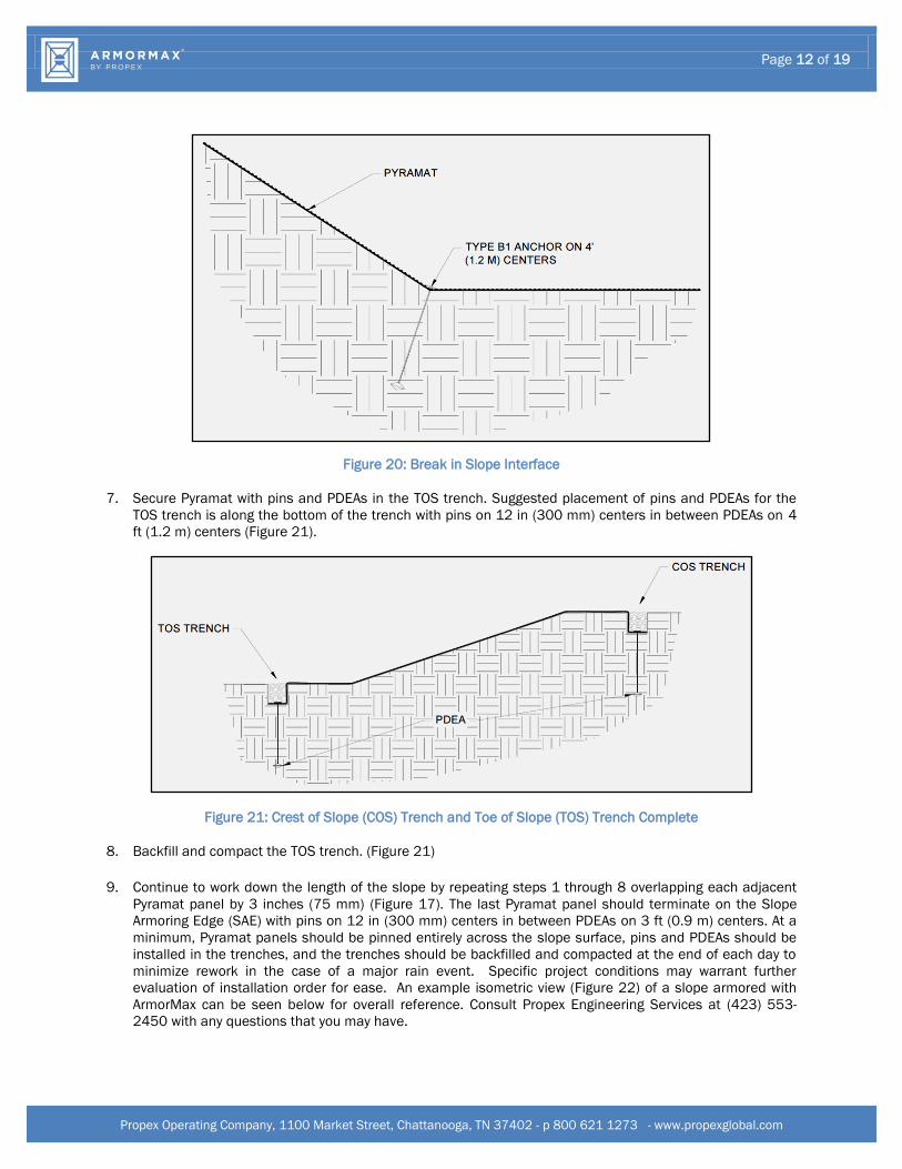
Figure 20: Break in Slope Interface
7. Secure Pyramat with pins and PDEAs in the TOS trench. Suggested placement of pins and PDEAs for the
TOS trench is along the bottom of the trench with pins on 12 in (300 mm) centers in between PDEAs on 4
ft (1.2 m) centers (Figure 21).
Figure 21: Crest of Slope (COS) Trench and Toe of Slope (TOS) Trench Complete
8. Backfill and compact the TOS trench. (Figure 21)
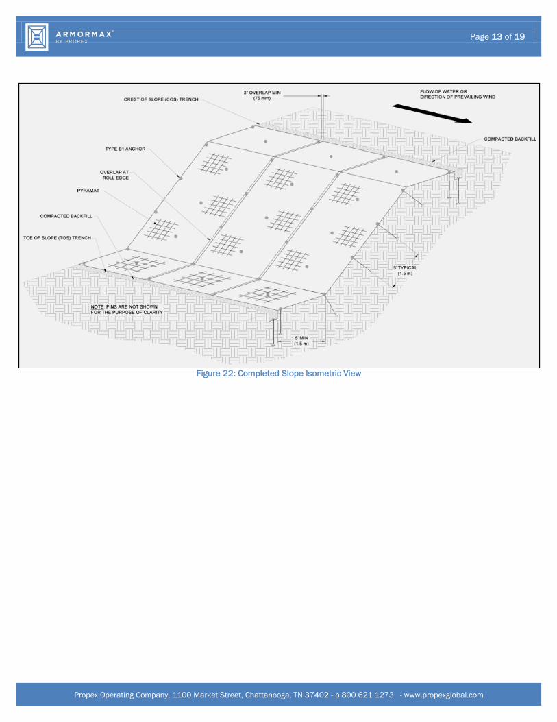
9. Continue to work down the length of the slope by repeating steps 1 through 8 overlapping each adjacent
Pyramat panel by 3 inches (75 mm) (Figure 17). The last Pyramat panel should terminate on the Slope
Armoring Edge (SAE) with pins on 12 in (300 mm) centers in between PDEAs on 3 ft (0.9 m) centers. At a
minimum, Pyramat panels should be pinned entirely across the slope surface, pins and PDEAs should be
installed in the trenches, and the trenches should be backfilled and compacted at the end of each day to
minimize rework in the case of a major rain event. Specific project conditions may warrant further
evaluation of installation order for ease. An example isometric view (Figure 22) of a slope armored with
ArmorMax can be seen below for overall reference. Consult Propex Engineering Services at (423) 553-
2450 with any questions that you may have.
Page 13 of 19
Propex Operating Company, 1100 Market Street, Chattanooga, TN 37402 - p 800 621 1273 - www.propexglobal.com
Figure 22: Completed Slope Isometric View

Page 14 of 19
Propex Operating Company, 1100 Market Street, Chattanooga, TN 37402 - p 800 621 1273 - www.propexglobal.com
ESTABLISH VEGETATION
Vegetation can be established with ArmorMax by broadcast seeding, hydraulic seed application (hydroseeding),
or sodding. Seed application rate, seed type, sod type, and irrigation rate should be selected based on local or
site specific knowledge and time of year. For best results, consider having a site specific soil test performed to
help determine what soil amendments, such as lime and fertilizer, need to be incorporated into the soil to
promote healthy vegetation.
WITH SEED
1. Determine the seed location. Seed can be placed entirely on top of soil filled ArmorMax, or alternatively
50% below ArmorMax prior to pinning and anchoring, with the remainder placed on top of soil filled
ArmorMax. If a rain event occurs prior to vegetation establishment, having 50% of the seed below
ArmorMax ensures that some seed remains in place. Seed placed entirely on top of soil filled ArmorMax
will allow for faster vegetation establishment.
2. If seeding below ArmorMax, ensure 50% of the seed is placed prior to the installation of ArmorMax.
3. Once ArmorMax is in place, distribute soil on top by filling the pyramid like projections of Pyramat. The
proper amount can be visually measured by making the top ridges of the pyramid projections barely
visible, or is approximately 1 inch thick when measured. Soil filling can be accomplished manually or by
using a small piece of equipment. Do not place excessive soil above ArmorMax. See Consider Project
Specific Needs for guidance on driving equipment across ArmorMax.
4. After seed has been placed, for added protection, install a Landlok Erosion Control Blanket (ECB) above
the soil-filled ArmorMax.
5. Irrigate as necessary to establish and maintain vegetation until 75% of vegetation has established and has
reached a height of 2 inches. Frequent, light irrigation will need to be applied to seeded areas if natural
rain events have not occurred within two weeks of seeding. When watering seeded areas, use a fine spray
to prevent erosion of seeds or soil. Do not over irrigate. Proper irrigation guidance is provided under the
Maintenance portion of this document.
WITH SOD
1. Sod will be always placed on top of ArmorMax.
2. Sod staples should be used to secure the sod against ArmorMax. During the placement of the sod, ensure
that ArmorMax is 100% covered by tightly adjoining rolls or squares of sod along edges. Any voids in
between sod pieces should be filled with clean loose soil.
3. Irrigate as necessary. Proper irrigation guidance is provided under the Maintenance portion of this
document.
4. Monitor to identify areas where browned/dead sod emerges. These areas may need to be addressed to
ensure proper sod establishment.

Page 15 of 19
Propex Operating Company, 1100 Market Street, Chattanooga, TN 37402 - p 800 621 1273 - www.propexglobal.com
CONSIDER PROJECT SPECIFIC NEEDS
1. For applications that require special transitions (i.e. connections to riprap, concrete, T-walls, etc.), refer to
the project specific drawings or consult with Propex Engineering Services at (423) 553-2450.
2. A deeper terminal trench and/or hard armoring may be required when slopes have severe scour potential
at the toe location.
3. For installing Pyramat panels around curved sections of a slope, trim panels at an angle so that no more
than two layers of Pyramat overlap at any point in time. Additional pins and PDEAs may be needed to
secure panel edges towards the toe of the slope depending upon the radius of the curved slope. Install
pins or PDEAs as necessary to securely fasten Pyramat to the ground.
4. Allowable Vehicle Traffic:
A. If using equipment on ArmorMax, it should be of the rubber-tired type and should avoid sharp turns.
Tracked equipment is not permitted to drive over the ArmorMax without vegetation at any time.
B. Avoid any traffic over ArmorMax if loose or wet soil conditions exist.
5. Disturbed areas should be reseeded. If ruts or depressions develop for any reason, rework soil until
smooth and reseed such areas.

Page 16 of 19
Propex Operating Company, 1100 Market Street, Chattanooga, TN 37402 - p 800 621 1273 - www.propexglobal.com
SHORT-TERM AND LONG-TERM MAINTENANCE OF ARMORMAX
The purpose of this section is to provide some general guidelines for performing short-term and long-term
maintenance of ArmorMax with respect to maintaining vegetation reinforced with ArmorMax, and patching of
ArmorMax (in the event it needs to be removed or replaced). These procedures are to be considered minimum
guidelines for proper maintenance, and further maintenance techniques may be appropriate considering local
practices and procedures.
ARMORMAX PROTECTED SLOPES
For ArmorMax to be most effective, it is important to ensure that it is properly maintained both during
construction and after construction. Identifying trouble areas is easy with ArmorMax, and it can make
identifying potential threats much simpler and manageable. Look for areas with sparse, dying, or no
vegetation as these are obvious signs that ArmorMax is losing intimate contact with the slope surface. If loss
of ground surface occurs, ArmorMax will need to be removed and reinstalled as described in Patching and
Repairs Section after the eroded area is backfilled with compacted soil that is similar to material of the slope.
After ArmorMax is reinstalled, re-establish vegetation on the newly installed ArmorMax and disturbed areas.
Monitor the sites to determine if frequent watering may be required to establish vegetation.
To minimize exposure to unwanted maintenance and repair, ArmorMax armored slopes should be free of
unauthorized vehicular traffic. Routine maintenance and slope inspections should be performed with rubber
tired vehicles. Tracked equipment such as skid steers, excavators, or dozers should only be allowed to traffic
over ArmorMax in times of emergency after vegetation establishment is complete. Failure to control
unauthorized traffic can result in ArmorMax being damaged resulting in erosion below ArmorMax during storm
events. In addition, routine mowing maintenance should be used to keep the protected area free of unwanted
brush, saplings, and trees. Selective herbicides that target only the unwanted plants can be used as long as
the vegetation established with ArmorMax is not impaired. Failure to control the sapling and tree growth can
result in the trees being uprooted during a flood.
MAINTAINING VEGETATION
Good vegetative cover will ensure maximum performance of ArmorMax. Vegetative cover care starts before a
project is complete and is ongoing until all ArmorMax is installed. Vegetative cover should be given every
opportunity to grow and establish well. This will require that a contractor periodically fertilize, water, and mow
the grasses as needed until a project is complete in the short-term, with the owner of the slope fulfilling the
maintenance of the slope in a similar fashion for the long-term. For the entire lifecycle of ArmorMax, every
effort must be made to prevent unauthorized encroachments, grazing, vehicle traffic, the misuse of chemicals,
or burning during inappropriate seasons.
1. After the installation of vegetation is complete, immediately water and soak the entire area using a fine
spray to prevent erosion and loss of seeds. A suggested amount of water is identified below. Prior to
installation if using sod, the sod pads in storage should be kept moist at all times and not stored for more
than 24 hours from site arrival to installation. Warmer weather will necessitate more frequent applications
than listed below.
A. For each reach/segment of installed vegetation, watering shall be conducted immediately after each
installation or the day's work.
B. First 30 days, completed segments shall be watered daily with a minimum of 0.75 and a maximum of
1.0 inches per square foot per day (20,364 gallons minimum, 27,152 gallons maximum per acre per
day).

Page 17 of 19
Propex Operating Company, 1100 Market Street, Chattanooga, TN 37402 - p 800 621 1273 - www.propexglobal.com
C. Second 30 days, the watering may be reduced to 0.50 inches per square foot per day (13,576 gallons
maximum per acre per day) or as required based upon the condition of the sod.
D. Avoid excessive application of water, so that surface runoff does not occur. Runoff should be
prohibited. However, additional watering may be required for repaired or damaged areas.
4. Initial fertilizing should be applied 14 days after vegetation is placed, using 25-lbs per acre ammonium
nitrate or ammonium sulfate. Post-fertilization should be conducted 30 to 45 days after installation, using
an application rate of 25-lbs per acre (ammonium nitrate or ammonium sulfate). Application example: in
order to apply ammonium nitrate or ammonium sulfate at a rate of 25-lbs per acre, 75 lbs of 33-0-0 is
required.
5. Implement best practices for mowing over ArmorMax. While ArmorMax is designed to withstand non-
hydraulic stresses such as mowing, there are procedures to minimize exposure to unwanted damage.
A. Immediately after installation, signage and post shall be installed stating that "Vehicles and
Pedestrians are Prohibited from Access" on the slopes and the newly installed vegetation. Signage
shall be posted every 1,500 lineal feet.
B. Vegetated areas should be mowed to a height no less than 6 inches and no greater than 12 inches
from natural ground after a period of 60 days of growth. The excessive grass clippings created from
mowing shall be evenly spread on the slope section outside of the armored area. Periodic and final
grass mowing should be performed until final inspection and acceptance of slope work. Monitor the
vegetated areas throughout winter months and generate reports as needed, noting any issues that
should be addressed. Minimum mowing heights will depend on the vegetation density and should be
as follows:
i. 6" with 0 – 30% vegetation establishment
ii. 4" with 30 – 70% vegetation establishment
iii. 3" with 70 – 100% vegetation establishment
C. To prevent damage to the newly established vegetation, the mowing tractor should be fitted with 3-rib
agriculture tires. Note that tractors with 8-foot flail mowers provide best results. Tractors with 15-foot
brush hogs should avoid sharp turns up the slope to prevent damage to vegetation.
D. Mowing should not take place for a minimum of 48 hours after a rainfall event of 2 inches or more to
minimize the potential for rutting and/or damage to the slope surface. Maintenance mowing of the
slope should be done on a consistent basis to prevent vegetation growing to more than 3 feet in
height. This will minimize thatch thickness and potential damage to ArmorMax. If turn-around pads
are present, operate mowing equipment utilizing the turn-around pads to the fullest extent. The
mowing blade height over ArmorMax should be a minimum of 8 inches. However, should vegetation
grow to more than 3 feet in height, the mowing blade height for the condition should be a minimum of
12 inches.
6. Some special circumstances may exist. When mowing the crown of a slope with a crown or crest equal to
or exceeding 20%, it should be mowed with an articulating arm mower to minimize the potential for the
mower blades to catch ArmorMax at the slope surface. The articulating arm mower should be level on the
surface with the articulating arm extending over the crown. Pay close attention to areas where the slope
changes. The mower blades should be set at a minimum height of 8 inches. If ArmorMax is damaged by
the mowing blades at any time, mowing should stop immediately and further direction should be obtained
to continue activity. Repair the damaged area as described in the Patching and Repairs section below.
7. ArmorMax protected slopes are not as susceptible to animal burrowing due the tenacity of the ArmorMax;
however, inspections to detect the presence of burrowing animal activity are generally most effective
immediately after the slope has been mowed. Animal burrows that are identified should be thoroughly
excavated and inspected, backfilled with compacted soil that is similar to material of the slope, and

Page 18 of 19
Propex Operating Company, 1100 Market Street, Chattanooga, TN 37402 - p 800 621 1273 - www.propexglobal.com
vegetation re-established. This will avoid the possibility of water piping through unfilled portions of the
burrows. Should ArmorMax be damaged, it is to be repaired as described Patching and Repairs section
below.
PATCHING AND REPAIRS
ArmorMax may require localized repair at times. For emergency repairs, an adequate supply of ArmorMax
should be maintained in inventory with the necessary tools to install. This will allow for a timely, initial repair of
the system.
1. In order to identify areas in need of repair, the site should be patrolled immediately after mowing and after
rain events of 2 inches or more. When patrolling look for areas of sparse vegetation, exposed edges of
ArmorMax, and areas where direct contact between ArmorMax and the slope surface is compromised.
ArmorMax should be rated as Acceptable, Minimally Acceptable, or Unacceptable during inspection.
A. Acceptable (A) - The rated area is in satisfactory, acceptable condition, and will function as designed
and intended during the rain event. ArmorMax has no exposed edges, is installed tightly by
maintaining direct contact to the slope surface with no rilling beneath, and has over 90% vegetation
cover. There is no noticeable damage present.
B. Minimally Acceptable (M) - The rated area has a minor deficiency that needs to be corrected. The
minor deficiency will not seriously impair the functioning of the area during the next rain event;
however, the overall reliability of the project will be lowered because of the minor deficiency.
ArmorMax has 75% vegetation cover with un-vegetated patches as large as one square yard. Edges of
ArmorMax are exposed with noticeable damage. Minimal erosion has occurred underneath ArmorMax.
C. Unacceptable (U) - The rated area is unsatisfactory. The deficiency is so serious that the area will not
adequately function in the next rain event. ArmorMax has been physically torn, ripped, or lifted from
the slope surface. Less than 75% vegetation cover is present with un-vegetated patches being greater
than 1 square yard, and there is evidence that erosion is occurring beneath ArmorMax.
2. Repair any raised or exposed edges of ArmorMax by driving existing and additional pins or PDEAs along the
edges as necessary to securely fasten to the ground. Inspect areas where the vegetation is not growing on
top of ArmorMax. Many times this is an indicator that Pyramat has lost contact with the ground beneath.
Check for voids beneath ArmorMax and fill any holes, gullies, etc. with compacted fill material if possible.
Replace ArmorMax as described below.
3. To repair ArmorMax, cut out and remove damaged areas in a square configuration a minimum size of 2 ft
by 2 ft. Remove all vegetation and debris atop of ArmorMax. Loosen the top 1 to 2 in of soil in the patch
area then seed. The subgrade of area to be patched shall be prepared to be smooth and uniform and
transition smoothly into the in-situ area. Cut a square Pyramat patch a minimum of 12 in greater than the
damaged area for all four sides of the patch. Overlap the patch area in all directions a minimum of 12 in.
The patch overlaps shall be tucked under the existing damaged Pyramat material (Figure 23 and Figure
24)

Page 19 of 19
Propex Operating Company, 1100 Market Street, Chattanooga, TN 37402 - p 800 621 1273 - www.propexglobal.com
Figure 23: ArmorMax Patch Cross Section
Figure 24: ArmorMax Patch Plan View
4. Install Type B1 anchors on 2 ft (600 mm) (max) centers, and pins on 6 in (150 mm) (max) centers. For
larger areas of damage, anchors should be installed to match existing anchor pattern. Once ArmorMax is
in place, vegetate per project specifications.
SUMMARY
Maintenance should consist of watering and weeding, repair of all erosion, and any re-seeding as necessary to
establish a uniform stand of vegetation during construction and beyond. A minimum of 70% of the armored
area should be covered with no bare or dead spots greater than 10 ft2 (1 m2). Establishing vegetation should
not be mowed prior to 70% vegetative density and a minimum grass growth of 4 in (100 mm). Throughout the
duration of the project, the contractor should be responsible for mowing to facilitate growth and should not let
the vegetation in the armored areas exceed 18 in (450 mm). In addition, the Contractor should water all
grassed areas as often as necessary to establish satisfactory growth and to maintain its growth throughout the
duration of the project. After the project is complete, it is the responsibility of the Owner to maintain and
upkeep all ArmorMax installed areas for long term performance and best results as described herein for
superior slope armoring.