Embed Size (px)
Citation preview

1106 Second Street #636 Encinitas, CA 92024
(858) 790-1890 or (858) 790-1445 [email protected]
INSTALLATION GUIDE for
Buried Precast
Three‐Sided Arch Structures
INSTALLATION GUIDELINES 2
www.SPECSBridge.com
1.0 Foundation Preparation
ALL standard safety regulations must be followed. Prep subgrade, construct footing in accordance to
project specifications and available geotechnical report.
Tolerable variations in dimensions per plan are provided in the project specifications. Special care should be taken to ensure the top of footing elevation varies no more than ¼” over 10’.
The keyway horizontal alignment is critical when setting the precast units, especially on longer structures. Run the keyway to the end of the structure as shown on the plans.
For precast wingwall foundations, take care to follow the design slope along the wingwall foundations. Foundations should be form-finished on the back or fill side.
2.0 Site Preparation
Site must permit access for over-the-road trucks delivering the units and the crane. Verify the correct route with SPECS in advance, and share any local limitations for wide loads.
Traffic control is the responsibility of the contractor. A staging area for trucks is recommended to minimize
crane down time. Plan to stack empty trailers. Due to the weights of the trucks and units rutting
should be expected, proper equipment must be provided to repair non-paved areas to a level and safe delivery area.
Crane selection is critical for a successful installation, weights will be provided so the contractor and the crane company can properly size the crane with the site considerations
Make sure that items such as trees and power lines do not interfere with installation.
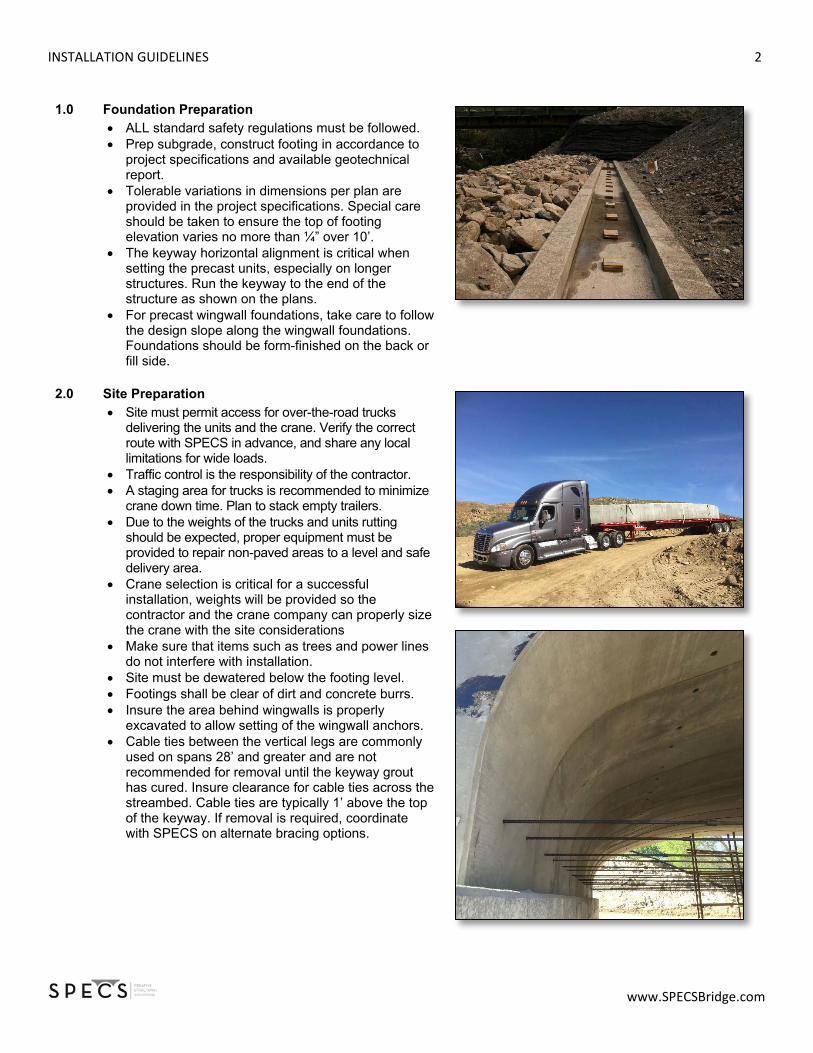
Site must be dewatered below the footing level. Footings shall be clear of dirt and concrete burrs. Insure the area behind wingwalls is properly
excavated to allow setting of the wingwall anchors. Cable ties between the vertical legs are commonly
used on spans 28’ and greater and are not recommended for removal until the keyway grout has cured. Insure clearance for cable ties across the streambed. Cable ties are typically 1’ above the top of the keyway. If removal is required, coordinate with SPECS on alternate bracing options.

INSTALLATION GUIDELINES 3
www.SPECSBridge.com
3.0 Planning the Installation Proper crane selection is vital to a successful installation. The crane provider should visit the site to assess the pick reach and be informed of the unit handling weight to properly size the crane and ensure the stability of the crane pad. Supply of the rigging material is the responsibility of the crane provider. SPECS will provide the specialty lifting apparatus. The typical installation crew includes a minimum of four members, up to eight depending on the complexity of the jobsite or installation. If the crane supplier doesn’t designate a signaler, one crew member should be assigned that role. - Clean or sweep the foundations to clear any debris. - Inspect the wingwall foundations to confirm the
width and check for adequate clearance behind the wall for the anchor.
- Confirm structure length and layout and foundation elevations against approved drawings.
- Start at the downstream end for projects with sloping foundations or either end if foundations are level.
- Measure from the end of the foundation to the structure limit and mark and secure a wood block to act as a stop point. Lay out the total length (or each piece) allowing for ½” joints between units and repeat on the opposite side.
- Chalk the outer edge of each bridge unit on both foundations to ensure the structure is aligned properly throughout the installation.
- Using a laser survey, pipe level or transit, identify and mark any high spots in the keyway. Using the high spot as the control, adjust shim stacks accordingly. Shims should be set roughly 12” from both ends of each arch unit leg. Shims should be roughly 1” above keyway. SPECS will provide 4” x 4” x ¼” masonite shims.
- For sloping foundations, shoot elevation control points at the foundation corners. Use a string line between control points. For structures exceeding 50 feet, use shim stacks at the foundation mid-point to support the string line.

INSTALLATION GUIDELINES 4
www.SPECSBridge.com
4.0 Handling Units Arch units will be delivered to the site either upright or (typically) on their side. Communicate with SPECS to determine the specific lifting mechanism needed prior to delivery. Arch units have a minimum of four lift holes or four
lifting inserts. The contractor shall use cables with a minimum
length of the following for each span: o 20 feet of cabling for spans under 26 feet o 30 feet of cabling for spans from 28 feet
through 42 feet o 40 feet of cabling for spans from 44 feet
through 60 feet Units delivered upright can be lifted off truck and set
into place. Units delivered on their side require a lay down area
and special care to insure easy installation and no damage to the units.
Units feature chamfered butt joints with a recommended ¼” to ½” joint spacing
Position 1-2 crew members on each side of the bridge with burke bars ready. When the crane lowers the arch unit into place, spud the precast arch up to the stop block. Check alignment against the previously detailed chalk lines and adjust to ensure the unit is aligned properly in the keyway.
o If the structure is level, check the vertical face for plumb; adjust as needed.
The first unit is a template for the entire structure, making the alignment of that first piece critical.
Arch units will set easier when the top hangs away from previously set arches; turn the unit in air.
To achieve a ¼” to ¾” joint, place shims between the leg of the adjacent arch to control the joint width.
Longer span units require a double drum crane and double lifting gear to turn units upright in the air.
NEVER have persons under the unit until it is securely placed onto footing
Spans 48’ and larger: end units with headwall must be supported in the center by an 8x8 supports, dunnage and hydraulic jack.
INSTALLATION GUIDELINES 5
www.SPECSBridge.com
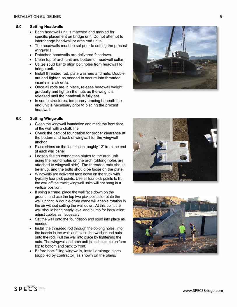
5.0 Setting Headwalls Each headwall unit is matched and marked for
specific placement on bridge unit. Do not attempt to interchange headwall or arch end units.
The headwalls must be set prior to setting the precast wingwalls.
Detached headwalls are delivered facedown. Clean top of arch unit and bottom of headwall collar. Utilize spud bar to align bolt holes from headwall to
bridge unit. Install threaded rod, plate washers and nuts. Double
nut and tighten as needed to secure into threaded inserts in arch units.
Once all rods are in place, release headwall weight gradually and tighten the nuts as the weight is released until the headwall is fully set.
In some structures, temporary bracing beneath the end unit is necessary prior to placing the precast headwall.
6.0 Setting Wingwalls
Clean the wingwall foundation and mark the front face of the wall with a chalk line.
Check the back of foundation for proper clearance at the bottom and back of wingwall for the wingwall anchor
Place shims on the foundation roughly 12” from the end of each wall panel.
Loosely fasten connection plates to the arch unit using the round holes on the arch (oblong holes are attached to wingwall side). The threaded rods should be snug, and the bolts should be loose on the plate.
Wingwalls are delivered face down on the truck with typically four pick points. Use all four pick points to lift the wall off the truck; wingwall units will not hang in a vertical position.
If using a crane, place the wall face down on the ground, and use the top two pick points to rotate the wall upright. A double-drum crane will enable rotation in the air without setting the wall down. At this point the wall should hang nearly level and plumb for installation; adjust cables as necessary.
Set the wall onto the foundation and spud into place as needed.
Install the threaded rod through the oblong holes, into the inserts in the wall, and place the washer and nuts onto the rod. Pull the wall into place by tightening the nuts. The wingwall and arch unit joint should be uniform top to bottom and back to front.
Before backfilling wingwalls, install drainage pipes (supplied by contractor) as shown on the plans.

INSTALLATION GUIDELINES 6
www.SPECSBridge.com
7.0 Joint Seal Procedure (complete prior to grout) Apply concrete primer using paint rollers or brushes.
Allow primer to dry to a tacky finish. Place the butyl rope between the chamfered joint
edges and cover with a minimum 9” wide joint wrap. The 9” wrap should be overlapped from the top a minimum of 6” as needed. The joint treatment should extend from the keyway, over the arch to the opposite keyway.
Headwall/bridge joints and all lift points shall have the same treatment.
Wingwall joint details are at the design engineer’s discretion.
SPECS will supply the primer, butyl rope and wrap. Alternative waterproofing applications are by specification and are not supplied by SPECS unless explicitly included by contract.
8.0 Grouting
Completely grout under bridge units as detailed in specifications.
Grout must completely flow under the arch units and fill the keyway. Vibrate from the outside as needed.
Fill all lift holes and insert locations (such as headwall collars) prior to applying joint treatment.
To grout beneath the wingwalls, position a temporary 2x4 on the front face of the wall to act as a form. Make sure the grout flows under the wall and beneath the anchor to the back of footing (grouted area shall be a minimum of 2’-6” wide by 6” deep).

INSTALLATION GUIDELINES 7
www.SPECSBridge.com
9.0 Backfilling
Backfilling is performed in accordance with SPECS’s specifications or the project specifications, whichever is more conservative. Fill heights over 12’ require a backfill compaction
testing plan has been coordinated with and approved by SPECS.
Units are backfilled and compacted in 8” lifts not to exceed 2’ of elevation differential on both sides of bridge.
Equipment in excess of design load on project drawings is NOT permitted over bridge unless approved by SPECS.
DO NOT backfill units until material has been approved by the project engineer of record.
The contractor must ensure the grout has reached design strength and the drainage pipes have been installed prior to placing and compacting backfill.
Use mechanical tampers or approved compacting equipment to compact all backfill and embankment immediately adjacent to each side of the structure and over the top of the structure to a minimum depth of 1’.
10.0 Contractor Jobsite Tools □ Minimum of (2) 60” burke bars
□ 48” spirit level
□ 2x4 board for wingwall grout forming
□ 2x4 board for keyway blocking
□ Transit level
□ (2) 10’ ladders
□ Chalk line and marking paint
□ Large box end / Crescent Wrenches for wing wall hardware
11.0 Jobsite Materials
□ Two copies of the structure installation drawings
□ (16 per unit) of 4” x 4” x ¼”) masonite shims
□ Oak shims and wedges
□ Concrete Primer, Joint wrap and butyl rope
□ Lift hole plugs
□ 2 sets of paint rollers and pans to place primer
□ Connection plates, washers, threaded rods and nuts
(provided by CONTRACTOR)
(provided by SPECS)
(provided by CONTRACTOR)
(provided by SPECS)
(provided by SPECS)
(provided by CONTRACTOR)
(provided by SPECS)