Embed Size (px)
Citation preview
Installation Guide
Manual 07.401.61.104 January 2017
Cyclo® HBBHelical Buddybox®

Cyclo® HBB Installation Guide 1Cyclo® HBB Installation Guide
Installation Guide
Cyclo® HBBHelical Buddybox®
Table of Contents Pages
InstallationShaft and Bushing
1Remove bushing guard.
2Loosen Taper-Grip® bolts.
3Remove bushing guard.
Shaft and Bushing Installation 1
Air Vent Locations 5
Torque Arms Moiunting Options 6
Turnbuckle and Clevis Type 6
Mount with “T” Type 8
Threaded Rod with “T” Type 12
Lubrication 14

2 Cyclo® HBB Installation Guide Cyclo® HBB Installation Guide 3
4Clean shaft with solvent. Do not use lubricant. Remove all grease, oil and anti-seize from the pulley journal shaft. Slide Taper-Grip® bushing on to shaft.
7Apply a thin layer of anti-seize paste to the male threads of the Taper-Grip® bushing only. Ensure that anti-seize paste does not enter the Taper-Grip® bushing bore.
5Inspect and test Taper-Grip® bushing on shaft.
8Screw Taper-Grip® bushing into Cyclo® HBB leaving approx. 1mm gap between the bushing flange and thrust collar.
6Remove Taper-Grip® bushing from shaft.
9Mount Cyclo® HBB on to shaft.
Do NOT apply anti-seize paste to the female threads in the hub.
Cyclo Min. Shaft Max Depth HBB Size Engagement to Shaft End TT (in.) TS (in.)
AA/Z 4.47 1.22 A 5.00 1.38 B 5.67 1.77 C 7.36 1.57 D 8.07 1.97 E 8.86 2.01TS TT
Do NOT rock or pry the unit.
Table 1. Minimum Shaft Engagement
Align
Leave 1 mm gap between bushing flange and thrust collar.
Be sure that bushing and shaft are aligned and Cyclo HBB weight is supported.
4 Cyclo® HBB Installation Guide Cyclo® HBB Installation Guide 5
HBBSize
Screw Size& Qty.
Screw Torque
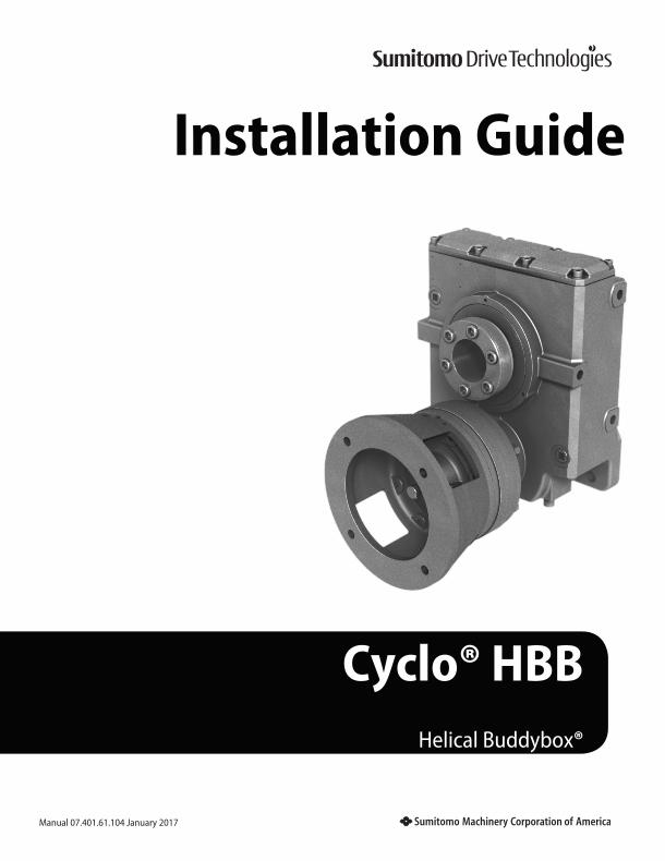
lb. ft NmAA/Z 6 X M10 22.9 31
A 6 X M12 37.6 51B 6 X M12 37.6 51C 6 X M16 94.4 128D 6 X M16 147.5 200E 8 X M16 147.5 200
10Screw bolts into Taper-Grip® bushing.
13Verify lubrication and install air vents.
14Finished Installation.
11Apply grease to shaft.
12Reinstall bushing guard over Taper-Grip® bushing.
• Lightly oil each bolt before inserting.
• Finger tighten to secure in place.
• Using a torque wrench, gradually tighten each bolt in a star pattern to specified torque levels.
• Apply grease or an anti-corrosion product on the exposed shaft after installing and tightening bushing bolts with a torque wrench.
• Ensure reducer is in the proper mounting position.
• Remove plugs and install air vents included in reducer package.
• An elbow is included for:
• Units are not shipped with oil, unless required by our customers.
• Please refer to Lubrication Section for further instructions on approved lubricants and quantities.
• Install Torque Arm assembly (see following pages).
• Check the following items:
• Check the Taper-Grip bushing screw torques after 20 - 30 hours of operation. If necessary, tighten the screws according to the torque chart in step 10. Check the screw torques every 6 months therafter.
Table 2. Bushing Bolt Torque
12
3
4
5
6
For units shipped with oil from the factory, removing plugs before placing unit in correct mounting position will cause oil to spill.
~ the gear portion when mounting in the Y2 and Y4 position. ~ the Cyclo® portion when mounting in the Y3 position.
- Oil Levels - Pre-wiring - Breather installed in HBB only for Cyclo® HBB sizes Z (AA), A and B - Breather installed in HBB and Cyclo® for Cyclo® HBB sizes C, D and E
HBB Breather Cyclo Breather
Y1
Cyclo Breather
HBB Breather
Y4
Cyclo Breather
HBB Breather
Y3
Cyclo Breather HBB Breather
Y2

6 Cyclo® HBB Installation Guide Cyclo® HBB Installation Guide 7
Torque Arm Mounting OptionsTurnbuckle and Clevis Type Torque Arm Installation Direct Mount Torque Arms in Tension
Perpendicular to output shaft axis
CW Shaft Rotation
CCW Shaft Rotation
CCW Shaft Rotation
CW Shaft Rotation
Not perpendicular
Aligned with housing Not aligned with housing
Not perpendicular
Correct
“Y1” Mounting Position
“Y3” Mounting Position
Incorrect
8 Cyclo® HBB Installation Guide Cyclo® HBB Installation Guide 9
Mount with “T” Type Torque Arm “T” Type Bracket Mounting - Two Options
Cyclo HBB Size
The Cyclo® HBB torque arm design allows for reversing rotation and can be mounted to accept loads in tension or compression.
In operation, the Cyclo® HBB will rotate in the opposite direction of the driven shaft, pulling away from the torque arm.
Tighten both pairs of nuts against the mounting tab so that there is zero clearance between the rubber bushings and the tab, but you can still rotate the rubber bushings by hand. Do not overtighten, but ensure that the nuts in each pair are tightened securely against each other so vibration will not cause them to loosen. Be sure that the bottom of the mounting angle bracket is secured to a rigid surface.
Item (Qty) SupplierZ609
AA409A610 A410
B612 B411
C614 C415
D616 D416
E617 E417
Assembly No. 998TATBBB-AAG 998TATBBB-AG 998TATBBB-BG 998TATBBB-CG 998TATBBB-DG 998TATBBB-EG
Torque Arm (1) SMA AN7610G NKML6166 NKML6167 NKML6168 NKML6169 NKML6170
Hardware Set, SMA• Rubber Bushing (3)• Washer (2)• Hex Nut (2)• Mounting Hardware (1 Set)
998TATPARTAAG 998TATPART-AG 998TATPART-BG 998TATPART-CG 998TATPART-DG 998TATPART-EG
Replacement Parts (ind.)
Rubber Bushing (3) SMA NKPA6379-5 NKPA6379-4 NKPA6379-3 NKPA6379-2 NKPA6379-2 NKPA6379-1
Washer (2) SMA NKPA6391-5 NKPA6391-4 NKPA6391-3 NKPA6391-2 NKPA6391-2 NKPA6391-1
Bolt and Nut (2) Customer M12 M16 M20 M24 M24 M30
Mounting Hardware (2ea.) SMA
M12 X 50 Hex-Screw
M12 Spring Lock WasherM12 Hex Nut
M16 X 55 Hex-Screw
M16 Spring Lock WasherM16 Hex Nut
M16 X 60 Hex-Screw
M16 Spring Lock WasherM16 Hex Nut
M20 X 75 Hex-Screw
M20 Spring Lock WasherM20 Hex Nut
M24 X 90 Hex-Screw
M24 Spring Lock WasherM24 Hex Nut
M30 X 110 Hex-Screw
M30 Spring Lock WasherM30 Hex Nut
Mounting Angle Bracket Hole Diameter (mm) (1) Customer
16 20 24 28 28 35
Required Bracket Clearance (mm) 13 16 16 21 21 26
6000 Series 4000 Series
Option 1 Option 2
HBBSize
y Dimension
x Dimension
Opt. 1 Opt. 2
AA/Z609 8.94 - 0.51
A610 9.39 1.97 0.71
B612 11.52 2.40 0.87
C614 14.06 3.11 1.22
D616 17.05 3.54 1.30
E617 18.98 4.72 1.93
Dimensions in Inches
Table 3. Mount with “T” Type Torque Arm Bracket Part Numbers
Option 1: “T” Type Bracket Mounting Option 2: “T” Type Bracket Mounting

10 Cyclo® HBB Installation Guide Cyclo® HBB Installation Guide 11
“T” Type Bracket Mounting
1Attach the “T” Type Bracket to the Cyclo® HBB using mounting hardware.
3Follow these steps to attach the mounting angle bracket:
4Attach mounting anglebracket to mounting surface.
2Place one washer and one rubber bushing on bolt.
Insert bolt through mounting tab on Cyclo® HBB.
Installation
• “T” Type Bracket and mounting bolts supplied by Sumitomo.
• Three rubber bushings and two washers supplied by Sumitomo.
• Bolt supplied by conveyor vendor. Minimum bolt grade is 8.8.
Table 4. “T” Type Bracket Bolt Torques
HBB Size Bolt Size Torque
4000 Series 6000 Series lb. ft Nm
AA409 Z609 M12 40-46 54-62
A410 A610 M16 92-130 125-176
B411 B612 M16 92-130 125-176
C415 C614 M20 191-270 259-366
D416 D616 M24 330-466 447-632
E417 E617 M30 655-923 888-1251
Make sure bolt is parallel to HBB when fully installed. See next page.
Do not overtighten nuts. Tighten to point where rubber bushings can still be rotated.
The mounting angle bracket must not interfere with the T-type torque arm bracket; there should be no contact during a 360° rotation of the pulley. Failure to maintain the required bracket clearance will cause catastrophic failure of the unit.
• Place rubber bushing and mounting angle bracket on bolt.
• Verify that the mounting angle bracket hole is the correct diameter (see table on page 8).
• Place remaining bushing, washer and two nuts on bolt.
• Check that bushings can still be hand rotated.
• Ensure that the required bracket clearance is correct (see table on page 8).

12 Cyclo® HBB Installation Guide Cyclo® HBB Installation Guide 13
Threaded Rod with “T” Type Bracket Mount
1Attach the “T” Type Bracket to the Cyclo® HBB using mounting hardware.
2Place two nuts, washer, and rubber bushing on bolt.
3Place remaining two nuts, washer, and rubber bushing on rod.
Insert bolt through mounting tab on Cyclo® HBB.
Installation
• “T” Type Bracket and mounting bolts supplied by Sumitomo.
• Rubber bushings and washers supplied by Sumitomo.
Table 4. “T” Type Bracket Bolt TorquesHBB Size Bolt Size Torque
4000 Series 6000 Series lb. ft NmAA409 Z609 M12 40-46 54-62A410 A610 M16 92-130 125-176B411 B612 M16 92-130 125-176C415 C614 M20 191-270 259-366D416 D616 M24 330-466 447-632E417 E617 M30 655-923 888-1251
Make sure rod is parallel to HBB when fully installed. See next page.
Do not overtighten nuts. Tighten to point where rubber bushings can still be hand rotated.
Correct and IncorrectThreaded Rod with “T” Type Bracket Installation

14 Cyclo® HBB Installation Guide Cyclo® HBB Installation Guide 15
Lubrication Lubrication (cont.)
Table L-1. Approved Oils
Table L-2. Oil Quantity
Oil lubricated reducers must be filled with oil prior to operation. Fill the reducer to the correct level with the approved oil.
G* indicates maintenance-free grease lubrication
For further instructions on Lubrication, please consult our O&M Manual.
Note: Normally grease-lubricated input portions are filled with grease prior to shipment.
Approved Oils
ExxonMobilMobilShell
IdemitsuKluberCaltex
BPCastrolGulfTotal
Spartan EPMobilgear 600XP
Omala S2 G
Daphne Super Gear OilKluberoil GEM1
Meropa
Energol GR-XPAlpha SP
EP Lubricant HDCarter EP
° F 14 32 50 68 86 104 122
° C -10 0 10 20 30 40 50
ISO VG68
100/150
220/320/460
Helical Buddybox
Size
Output side (HBB) Input side (Cyclo)
Y1 Y2 Y3 Y4 Y1 Y2 Y3 Y4
gal ℓ gal ℓ gal ℓ gal ℓ gal ℓ gal ℓ gal ℓ gal ℓ
AA/ Z 0.16 0.60 0.16 0.60 0.13 0.49 0.16 0.60 G* G G G G G G G
A 0.21 0.80 0.24 0.91 0.18 0.68 0.24 0.91 G G G G G G G G
B 0.26 0.98 0.40 1.51 0.26 0.98 0.40 1.51 G G G G G G G G
C 0.45 1.70 0.55 2.10 0.34 1.30 0.55 2.10 0.11 0.40 0.11 0.40 0.11 0.40 0.11 0.40
D 0.71 2.70 0.92 3.50 0.53 2.00 0.92 3.50 0.18 0.70 0.18 0.70 0.18 0.70 0.18 0.70
E 0.92 3.50 1.11 4.20 0.66 2.50 1.11 4.20 0.24 0.90 0.24 0.90 0.24 0.90 0.24 0.90

16 Cyclo® HBB Installation Guide Cyclo® HBB Installation Guide 17
Notes Notes
4200 Holland BoulevardChesapeake, VA 23323Tel: +1-757-485-3355 • 1-800-SMCYCLO Fax: +1-757-485-7490www.sumitomodrive.comE-mail: [email protected]
www.sumitomodrive.com 1-800-SM-CYCLO
After Hours Technical Support [email protected] 1-800-983-1000
World Headquarters
JapanSumitomo Heavy Industries, Ltd.Power Transmission & Controls GroupThinkPark Tower, 1-1, Osaki 2-chome,Shinagawa-ku, Tokyo 141-6025 JapanTel: +81-367-37-2511 • Fax: +81-368-66-5160
For facilities located in the Americas, please visit www.sumitomodrive.com/locations
For worldwide locations, please visit www.sumitomodrive.com/worldwide
Cyclo® HBBwww.sumitomodrive.com/HBB
Headquarters & Manufacturing