Embed Size (px)
Citation preview
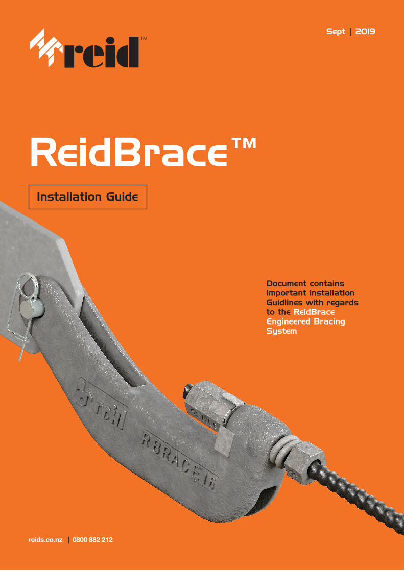
ReidBrace™Installation Guide
Document contains important installation Guidlines with regards to the ReidBrace Engineered Bracing System
reids.co.nz | 0800 882 212
Sept | 2019
1
2
3
5
6
4
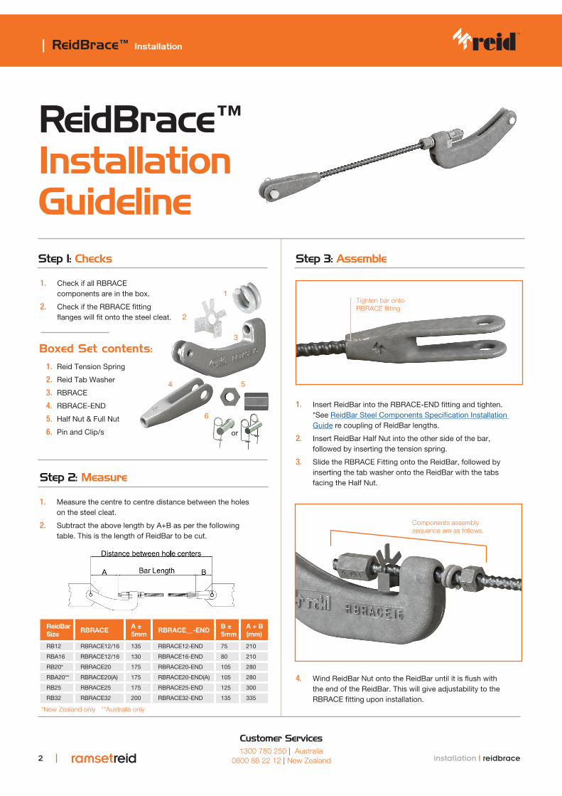
ReidBrace™ Installation Guideline
| ReidBrace™ Installation
2 installation | reidbrace
1. Check if all RBRACE components are in the box.
2. Check if the RBRACE fitting flanges will fit onto the steel cleat.
Step 1: Checks
1. Measure the centre to centre distance between the holes on the steel cleat.
2. Subtract the above length by A+B as per the following table. This is the length of ReidBar to be cut.
Step 2: Measure
Boxed Set contents:1. Reid Tension Spring
2. Reid Tab Washer
3. RBRACE
4. RBRACE-END
5. Half Nut & Full Nut
6. Pin and Clip/s
1. Insert ReidBar into the RBRACE-END fitting and tighten. *See ReidBar Steel Components Specification Installation Guide re coupling of ReidBar lengths.
2. Insert ReidBar Half Nut into the other side of the bar, followed by inserting the tension spring.
3. Slide the RBRACE Fitting onto the ReidBar, followed by inserting the tab washer onto the ReidBar with the tabs facing the Half Nut.
Step 3: Assemble
4. Wind ReidBar Nut onto the ReidBar until it is flush with the end of the ReidBar. This will give adjustability to the RBRACE fitting upon installation.
ReidBar Size
RBRACEA ± 5mm
RBRACE__-ENDB ± 5mm
A + B (mm)
RB12 RBRACE12/16 135 RBRACE12-END 75 210
RBA16 RBRACE12/16 130 RBRACE16-END 80 210
RB20* RBRACE20 175 RBRACE20-END 105 280
RBA20** RBRACE20(A) 175 RBRACE20-END(A) 105 280
RB25 RBRACE25 175 RBRACE25-END 125 300
RB32 RBRACE32 200 RBRACE32-END 135 335
Tighten bar onto RBRACE fitting
Components assembly sequence are as follows.
Customer Services1300 780 250 | Australia
0800 88 22 12 | New Zealand
*New Zealand only **Australia only
or
L/100
L
ReidBrace™ Installation Guideline
| ReidBrace™ Installation
3 installation | reidbrace
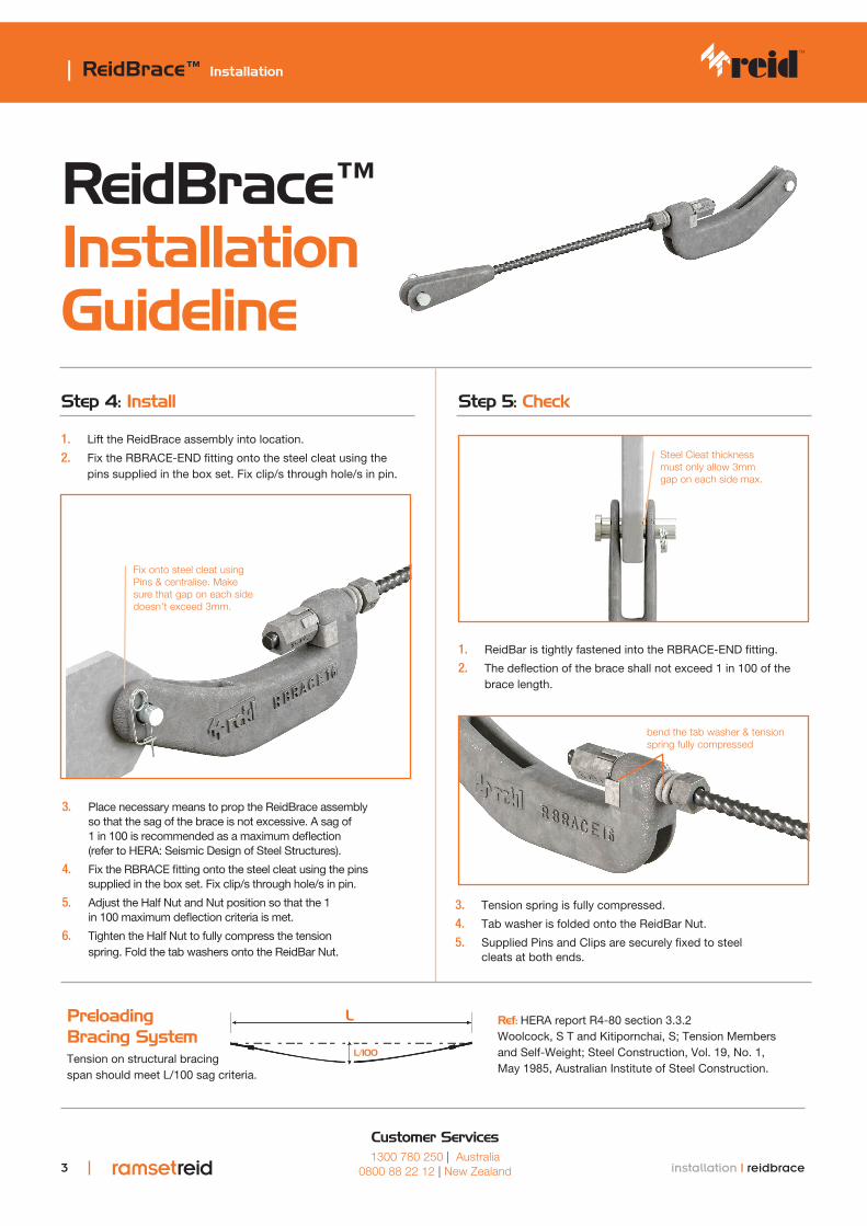
1. Lift the ReidBrace assembly into location.
2. Fix the RBRACE-END fitting onto the steel cleat using the pins supplied in the box set. Fix clip/s through hole/s in pin.
Step 4: Install
1. ReidBar is tightly fastened into the RBRACE-END fitting.
2. The deflection of the brace shall not exceed 1 in 100 of the brace length.
Step 5: Check
3. Place necessary means to prop the ReidBrace assembly so that the sag of the brace is not excessive. A sag of 1 in 100 is recommended as a maximum deflection (refer to HERA: Seismic Design of Steel Structures).
4. Fix the RBRACE fitting onto the steel cleat using the pins supplied in the box set. Fix clip/s through hole/s in pin.
5. Adjust the Half Nut and Nut position so that the 1 in 100 maximum deflection criteria is met.
6. Tighten the Half Nut to fully compress the tension spring. Fold the tab washers onto the ReidBar Nut.
3. Tension spring is fully compressed.
4. Tab washer is folded onto the ReidBar Nut.
5. Supplied Pins and Clips are securely fixed to steel cleats at both ends.
Fix onto steel cleat using Pins & centralise. Make sure that gap on each side doesn't exceed 3mm.
Steel Cleat thickness must only allow 3mm gap on each side max.
bend the tab washer & tension spring fully compressed
Customer Services1300 780 250 | Australia
0800 88 22 12 | New Zealand
Preloading Bracing SystemTension on structural bracing span should meet L/100 sag criteria.
Ref: HERA report R4-80 section 3.3.2 Woolcock, S T and Kitipornchai, S; Tension Members and Self-Weight; Steel Construction, Vol. 19, No. 1, May 1985, Australian Institute of Steel Construction.