Embed Size (px)
Citation preview

Business Networking Solution
Installation GuideGigabit Unmanaged Switch
TL-SG1008/TL-SG1008PETL-SG1016/TL-SG1016DTL-SG1024/TL-SG1024D
TL-SG1048

IRelated Document
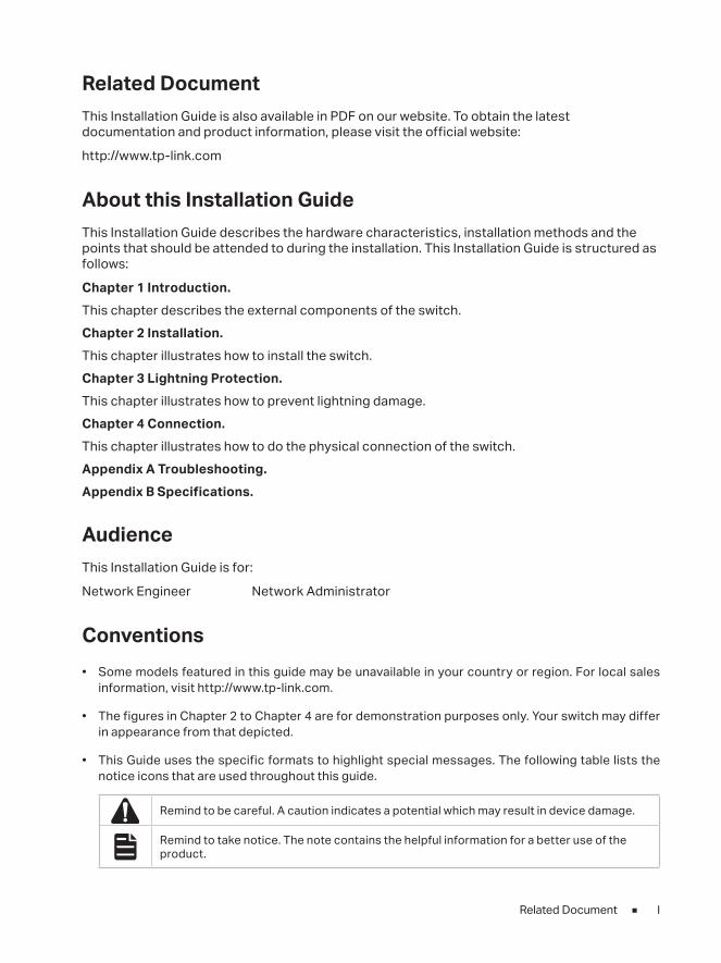
Related DocumentThis Installation Guide is also available in PDF on our website. To obtain the latest documentation and product information, please visit the official website:
http://www.tp-link.com
About this Installation Guide This Installation Guide describes the hardware characteristics, installation methods and the points that should be attended to during the installation. This Installation Guide is structured as follows:
Chapter 1 Introduction. This chapter describes the external components of the switch.Chapter 2 Installation. This chapter illustrates how to install the switch.Chapter 3 Lightning Protection. This chapter illustrates how to prevent lightning damage.Chapter 4 Connection. This chapter illustrates how to do the physical connection of the switch.Appendix A Troubleshooting.Appendix B Specifications.
Audience This Installation Guide is for:
Network Engineer Network Administrator
Conventions • Some models featured in this guide may be unavailable in your country or region. For local sales
information, visit http://www.tp-link.com.
• The figures in Chapter 2 to Chapter 4 are for demonstration purposes only. Your switch may differ in appearance from that depicted.
• This Guide uses the specific formats to highlight special messages. The following table lists the notice icons that are used throughout this guide.
Remind to be careful. A caution indicates a potential which may result in device damage.
Remind to take notice. The note contains the helpful information for a better use of the product.
II
Contents
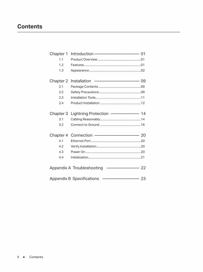
Chapter 1 Introduction ——————————— 011.1 Product Overview ...........................................................011.2 Features ..............................................................................011.3 Appearance .......................................................................02
Chapter 2 Installation ——————————— 092.1 Package Contents ..........................................................092.2 Safety Precautions .........................................................092.3 Installation Tools ..............................................................112.4 Product Installation ........................................................12
Chapter 3 Lightning Protection ——————— 143.1 Cabling Reasonably........................................................143.2 Connect to Ground .........................................................16
Chapter 4 Connection ——————————— 204.1 Ethernet Port ....................................................................204.2 Verify Installation .............................................................204.3 Power On ............................................................................204.4 Initialization ........................................................................21
Appendix A Troubleshooting ———————— 22
Appendix B Specifications ————————— 23
Contents
Gigabit Unmanaged Switch
01Introduction
Chapter 1 Introduction
1.1 Product Overview
The Gigabit Unmanaged Switch provides you with a high-performance, low-cost, easy-to-use, seamless and standard upgrade to boost your old network to 1000Mbps. By increasing the speed of your network server and backbone connections, the Gigabit Unmanaged Switch makes Gigabit a reality. Power users in the home, office, workgroup, or creative production environment can now move large, bandwidth-intensive files faster. Graphics, CGI, CAD, multimedia files and other large files moved by some applications can be transferred across the network almost instantly.
The Gigabit Unmanaged Switch features a non-blocking switching architecture that forwards and filters packets at full wire-speed for maximum throughput. The switch supports MAC address auto-learning and auto-aging. It is compatible with all 10Mbps, 100Mbps and 1000Mbps Ethernet devices because it is standard-based. It protects your existing network investments while providing you with a straightforward migration path to faster Gigabit speed.
The Gigabit Unmanaged Switch is plug-and-play and no configuration is required. Auto MDI/MDI-X cable detection on all ports eliminates the need for crossover cable or Uplink port. Each port can be used as general port or Uplink port, and any port can be simply plugged into a server, a hub, a router or a switch, using the straight cable or crossover cable. Diagnostic LEDs which display link status and activity, allow you to quickly detect and correct problems on the network.
TL-SG1008PE is a Power Sourcing Equipment (PSE*). The 8 Auto-Negotiation RJ45 ports support Power over Ethernet (PoE*) function, which can automatically detect and supply power with those IEEE802.3af/IEEE802.3at-compliant powered devices (PDs*).
Note: ■ *PSE is a device (switch or hub for instance) that will provide power in a PoE setup. ■ *PoE is a technology that describes a system to transmit electrical power, along
with data, to remote devices over standard twisted-pair cable in an Ethernet network.
■ *PD is a device powered by a PSE and thus consumes energy. Examples include powering IP telephones, wireless LAN access points, network cameras, network hubs, embedded computers etc.
1.2 Features
For TL-SG1048/TL-SG1024/TL-SG1024D/TL-SG1016/TL-SG1016D/TL-SG1008: ■ Complies with IEEE802.3i, IEEE802.3u, IEEE802.3ab standards
■ 8/16/24/48 10/100/1000Mbps Auto-Sense RJ45 ports supporting Auto-MDI/MDIX
■ All ports support Full/Half Duplex transfer mode for 10/100Mbps and Full Duplex transfer mode for 1000Mbps
Gigabit Unmanaged Switch
02 Introduction
■ TL-SG1024/TL-SG1024D/TL-SG1016/TL-SG1016D/TL-SG1008 supports IEEE802.3x flow control for full-duplex mode and backpressure for half-duplex transfer mode
■ TL-SG1008 supports IEEE802.1p standard
■ Non-blocking switching architecture that forwards and filters packets at full wire-speed for maximum throughput
■ Supports MAC address auto-learning and auto-aging
■ Desktop and rack-mountable steel case
■ Internal power supply
For TL-SG1008PE: ■ Complies with IEEE802.3i, IEEE802.3u, IEEE802.3ab, IEEE802.3x, IEEE802.3af,
IEEE802.1p and IEEE802.3at standards
■ 8 10/100/1000Mbps Auto-Negotiation RJ45 ports all supporting PoE function and Auto-MDI/MDIX
■ Supports PoE power up to 126W for all PoE ports
■ Supports PoE IEEE802.3af/IEEE802.3at-compliant PDs
■ Supports IEEE802.3x flow control for Full-duplex Mode and backpressure for Half-duplex Mode
■ 4K MAC address table of the TL-SG1008PE with auto-learning and auto-aging
■ Internal power supply
1.3 Appearance
■ Front Panel
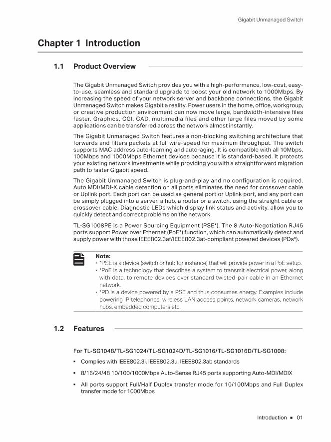
The front panel of TL-SG1048 is shown as the following figure.Figure 1-1 Front Panel of TL-SG1048
10/100/1000Mbps RJ45 Port
LEDs
Gigabit Unmanaged Switch
03Introduction
LEDs
LED Status Indication
PowerOn The switch is powered on. Off The switch is powered off or power supply is abnormal.
Link/ActOn
Green The corresponding port is running at 1000Mbps.Yellow The corresponding port is running at 10/100Mbps.
Flashing The corresponding port is transmitting or receiving data.Off There is no device linked to the corresponding port.
10/100/1000Mbps RJ45 PortDesigned to connect to the device with a bandwidth of 10Mbps, 100Mbps or 1000Mbps. Each has a corresponding Link/Act LED.
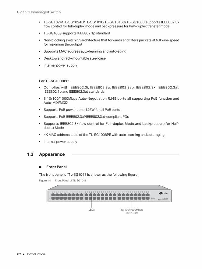
The front panel of TL-SG1024 is shown as the following figure.Figure 1-2 Front Panel of TL-SG1024
10/100/1000Mbps RJ45 Port
LEDs
The front panel of TL-SG1016 is shown as the following figure.Figure 1-3 Front Panel of TL-SG1016
10/100/1000Mbps RJ45 Port
LEDs
The front panel of TL-SG1024D is shown as the following figure.Figure 1-4 Front Panel of TL-SG1024D
10/100/1000Mbps RJ45 Port
LEDs
Gigabit Unmanaged Switch
04 Introduction
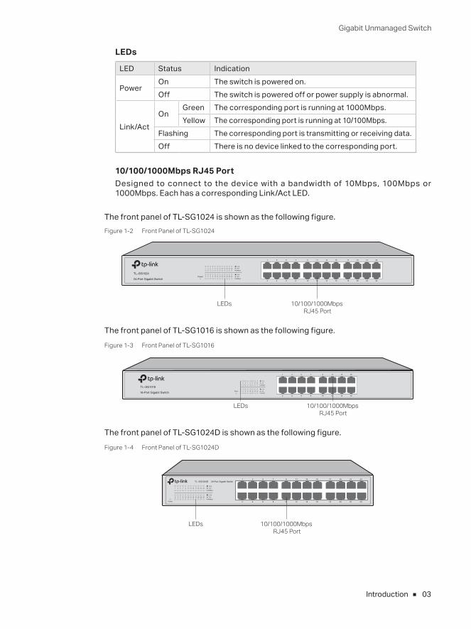
The front panel of TL-SG1016D is shown as the following figure.Figure 1-5 Front Panel of TL-SG1016D
10/100/1000Mbps RJ45 Port
LEDs
The front panel of TL-SG1008 is shown as the following figure.Figure 1-6 Front Panel of TL-SG1008
Power
1 2 3 4 5 6 7 8
1 2 3 4 5 6 7 8LinkAct
1000Mbps
TL-SG1008 8-Port Gigabit Switch
10/100/1000Mbps RJ45 Port
LEDs
LEDs
LED Status Indication
PowerOn The switch is powered on.Off The switch is powered off or power supply is abnormal.
Link/ActOn There is a device linked to the corresponding port but no
activity.Flashing The corresponding port is transmitting or receiving data.Off There is no device linked to the corresponding port.
1000MbpsOn The corresponding port is running at 1000Mbps.
Off The corresponding port is not running at 1000Mbps or has no link.
10/100/1000Mbps RJ45 PortDesigned to connect to the device with a bandwidth of 10Mbps, 100Mbps or 1000Mbps. Each has a corresponding Link/Act LED and a 1000Mbps LED.
Gigabit Unmanaged Switch
05Introduction
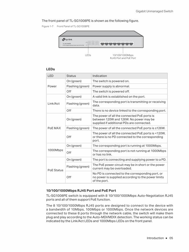
The front panel of TL-SG1008PE is shown as the following figure.Figure 1-7 Front Panel of TL-SG1008PE
10/100/1000Mbps RJ45 Port and PoE Port
LEDs
LEDs
LED Status Indication
PowerOn (green) The switch is powered on.Flashing (green) Power supply is abnormal.Off The switch is powered off.
Link/Act
On (green) A valid link is established on the port.
Flashing (green) The corresponding port is transmitting or receiving data.
Off There is no device linked to the corresponding port.
PoE MAX
On (green)The power of all the connected PoE ports is between 120W and 126W. No power may be supplied if additional PDs are connected.
Flashing (green) The power of all the connected PoE ports is ≥126W.
OffThe power of all the connected PoE ports is <120W, or there is no PD connected to the corresponding port.
1000MbpsOn (green) The corresponding port is running at 1000Mbps.
Off The corresponding port is not running at 1000Mbps or has no link.
PoE Status
On (green) The port is connecting and supplying power to a PD.
Flashing (green) The PoE power circuit may be in short or the power current may be overloaded.
OffNo PD is connected to the corresponding port, or no power is supplied according to the power limits of the port.
10/100/1000Mbps RJ45 Port and PoE PortTL-SG1008PE switch is equipped with 8 10/100/1000Mbps Auto-Negotiation RJ45 ports and all of them support PoE function.
The 8 10/100/1000Mbps RJ45 ports are designed to connect to the device with a bandwidth of 10Mbps, 100Mbps or 1000Mbps. Once the network devices are connected to these 8 ports through the network cable, the switch will make them plug and play according to the Auto-MDI/MDIX detection. The working status can be indicated by the Link/Act LEDs and 1000Mbps LEDs on the front panel.
Gigabit Unmanaged Switch
06 Introduction
The 8 ports also support PoE function which integrates power and data onto one Ethernet cable. Once the device you connect to the switch is identified, the switch will supply power through the PoE port, and then you can use it as a 10/100/1000Mbps Auto-Negotiation RJ45 Ethernet port. The working status can be indicated by the PoE MAX LED and PoE Status LEDs on the front panel.
Note: ■ Make sure the PDs you connected to the switch are compliant with IEEE802.3af/IEEE802.3at standard.
■ If all PoE PDs power consumption is ≥126W, a priority* will be arranged among the PoE ports like port 1 > port 2 > port 3 > port 4 > port 5 > port 6 > port 7 > port 8, then the system will cut off the power of the lowest-priority port.
■ *Priority is to protect the system when the system power is overloaded. For example, Port 1, 2, 4 and 7 is using 30; the system power is 120W in total. If there is an additional PD inserted to Port 3 with 25W, and then the system will cut off the power of Port 7 because of the overloaded power, this means Port 1, 2 and 4 will use 30W, and Port 3 will use 25W, no power will be supplied to Port 7.
■ Rear Panel
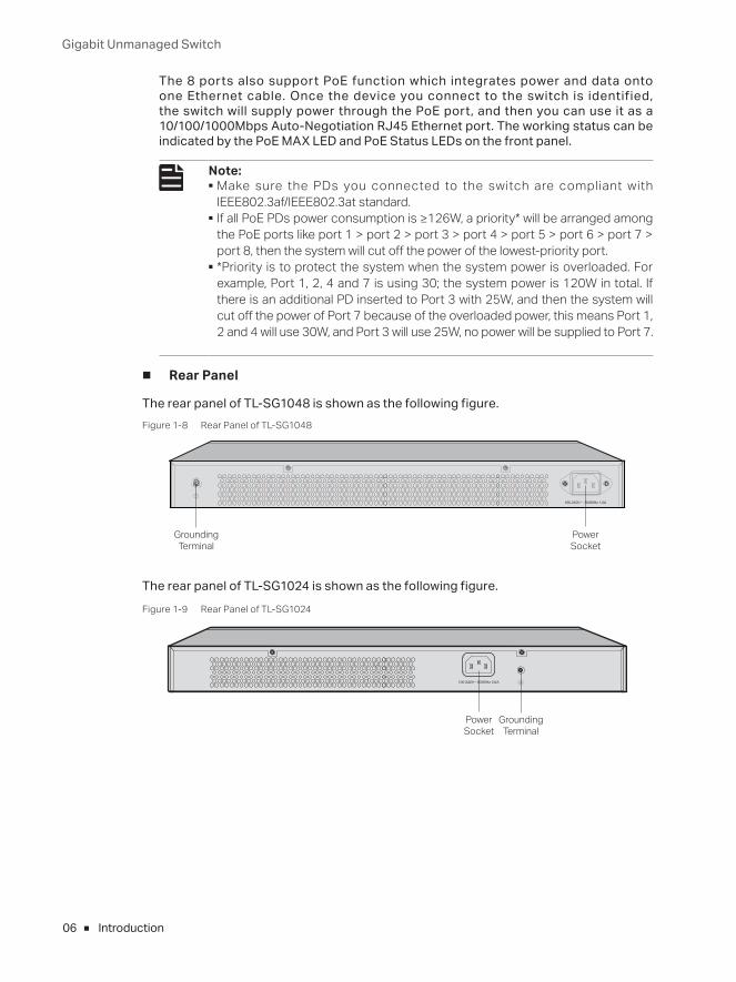
The rear panel of TL-SG1048 is shown as the following figure.Figure 1-8 Rear Panel of TL-SG1048
Power Socket
Grounding Terminal
The rear panel of TL-SG1024 is shown as the following figure.Figure 1-9 Rear Panel of TL-SG1024
Power Socket
Grounding Terminal
Gigabit Unmanaged Switch
07Introduction
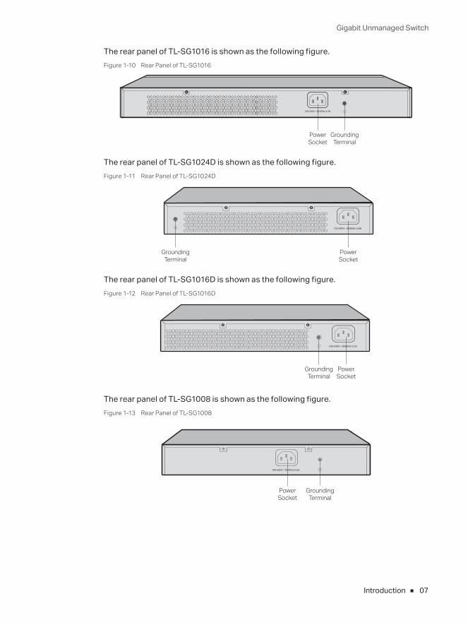
The rear panel of TL-SG1016 is shown as the following figure.Figure 1-10 Rear Panel of TL-SG1016
Power Socket
Grounding Terminal
The rear panel of TL-SG1024D is shown as the following figure.Figure 1-11 Rear Panel of TL-SG1024D
Power Socket
Grounding Terminal
The rear panel of TL-SG1016D is shown as the following figure.Figure 1-12 Rear Panel of TL-SG1016D
Power Socket
Grounding Terminal
The rear panel of TL-SG1008 is shown as the following figure.Figure 1-13 Rear Panel of TL-SG1008
Grounding Terminal
Power Socket
Gigabit Unmanaged Switch
08 Introduction
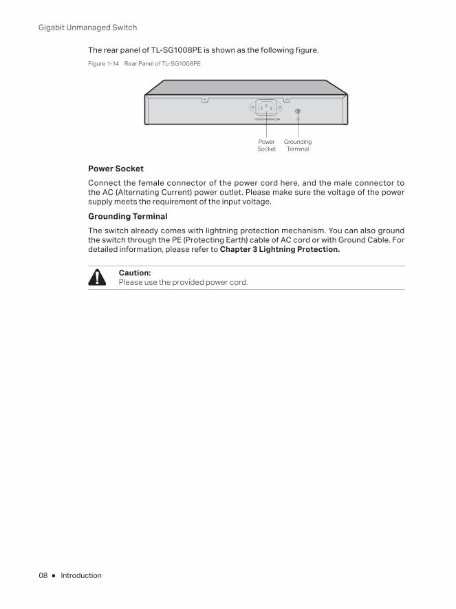
The rear panel of TL-SG1008PE is shown as the following figure.Figure 1-14 Rear Panel of TL-SG1008PE
Grounding Terminal
Power Socket
Power Socket Connect the female connector of the power cord here, and the male connector to the AC (Alternating Current) power outlet. Please make sure the voltage of the power supply meets the requirement of the input voltage.
Grounding TerminalThe switch already comes with lightning protection mechanism. You can also ground the switch through the PE (Protecting Earth) cable of AC cord or with Ground Cable. For detailed information, please refer to Chapter 3 Lightning Protection.
Caution: Please use the provided power cord.
Gigabit Unmanaged Switch
09Installation
Chapter 2 Installation
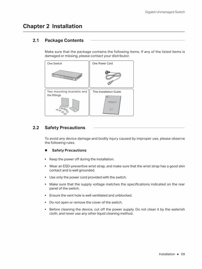
2.1 Package Contents
Make sure that the package contains the following items. If any of the listed items is damaged or missing, please contact your distributor.
One Power CordOne Switch
This Installation Guide
Installation Guide
Business Networking Solution
Two mounting brackets and the fittings
2.2 Safety Precautions
To avoid any device damage and bodily injury caused by improper use, please observe the following rules.
■ Safety Precautions
■ Keep the power off during the installation.
■ Wear an ESD-preventive wrist strap, and make sure that the wrist strap has a good skin contact and is well grounded.
■ Use only the power cord provided with the switch.
■ Make sure that the supply voltage matches the specifications indicated on the rear panel of the switch.
■ Ensure the vent hole is well ventilated and unblocked.
■ Do not open or remove the cover of the switch.
■ Before cleaning the device, cut off the power supply. Do not clean it by the waterish cloth, and never use any other liquid cleaning method.
Gigabit Unmanaged Switch
10 Installation
■ Site Requirements
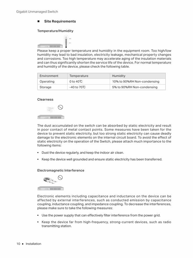
Temperature/Humidity
40℃
0℃
Please keep a proper temperature and humidity in the equipment room. Too high/low humidity may lead to bad insulation, electricity leakage, mechanical property changes and corrosions. Too high temperature may accelerate aging of the insulation materials and can thus significantly shorten the service life of the device. For normal temperature and humidity of the device, please check the following table.
Environment Temperature Humidity
Operating 0 to 40℃ 10% to 90%RH Non-condensing
Storage -40 to 70℃ 5% to 90%RH Non-condensing
Clearness
The dust accumulated on the switch can be absorbed by static electricity and result in poor contact of metal contact points. Some measures have been taken for the device to prevent static electricity, but too strong static electricity can cause deadly damage to the electronic elements on the internal circuit board. To avoid the effect of static electricity on the operation of the Switch, please attach much importance to the following items:
■ Dust the device regularly, and keep the indoor air clean.
■ Keep the device well grounded and ensure static electricity has been transferred.
Electromagnetic Interference
Electronic elements including capacitance and inductance on the device can be affected by external interferences, such as conducted emission by capacitance coupling, inductance coupling, and impedance coupling. To decrease the interferences, please make sure to take the following measures:
■ Use the power supply that can effectively filter interference from the power grid.
■ Keep the device far from high-frequency, strong-current devices, such as radio transmitting station.
Gigabit Unmanaged Switch
11Installation
■ Use electromagnetic shielding when necessary.
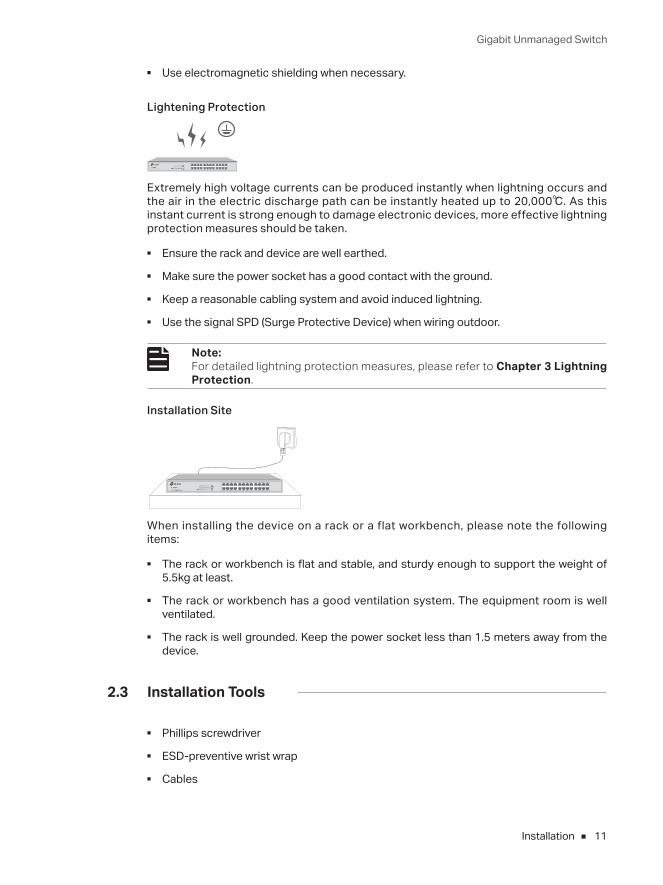
Lightening Protection
Extremely high voltage currents can be produced instantly when lightning occurs and the air in the electric discharge path can be instantly heated up to 20,000℃. As this instant current is strong enough to damage electronic devices, more effective lightning protection measures should be taken.
■ Ensure the rack and device are well earthed.
■ Make sure the power socket has a good contact with the ground.
■ Keep a reasonable cabling system and avoid induced lightning.
■ Use the signal SPD (Surge Protective Device) when wiring outdoor.
Note: For detailed lightning protection measures, please refer to Chapter 3 Lightning Protection.
Installation Site
When installing the device on a rack or a flat workbench, please note the following items:
■ The rack or workbench is flat and stable, and sturdy enough to support the weight of 5.5kg at least.
■ The rack or workbench has a good ventilation system. The equipment room is well ventilated.
■ The rack is well grounded. Keep the power socket less than 1.5 meters away from the device.
2.3 Installation Tools
■ Phillips screwdriver
■ ESD-preventive wrist wrap
■ Cables
Gigabit Unmanaged Switch
12 Installation
Note: These tools are not provided with our product. If needed, please self purchase them.
2.4 Product Installation
■ Desktop Installation
To install the device on the desktop, please follow the steps:
1. Set the device on a flat surface strong enough to support the entire weight of the device with all fittings.
2. Remove the adhesive backing papers from the rubber feet.
3. Turnover the device and attach the supplied rubber feet to the recessed areas on the bottom at each corner of the device.
FeetBottom of the Device
Notch
Figure 2-1 Desktop Installation
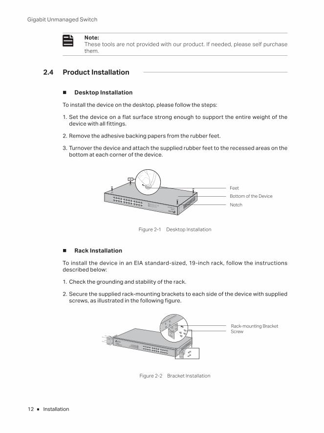
■ Rack Installation
To install the device in an EIA standard-sized, 19-inch rack, follow the instructions described below:
1. Check the grounding and stability of the rack.
2. Secure the supplied rack-mounting brackets to each side of the device with supplied screws, as illustrated in the following figure.
Rack-mounting BracketScrew
Figure 2-2 Bracket Installation
Gigabit Unmanaged Switch
13Installation
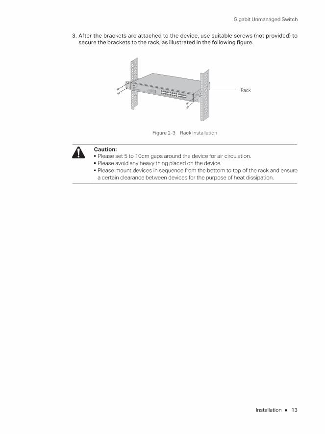
3. After the brackets are attached to the device, use suitable screws (not provided) to secure the brackets to the rack, as illustrated in the following figure.
Rack
Figure 2-3 Rack Installation
Caution: ■ Please set 5 to 10cm gaps around the device for air circulation. ■ Please avoid any heavy thing placed on the device. ■ Please mount devices in sequence from the bottom to top of the rack and ensure a certain clearance between devices for the purpose of heat dissipation.
Gigabit Unmanaged Switch
14 Lightning Protection
Chapter 3 Lightning Protection
3.1 Cabling Reasonably
In the actual network environment, you may need cable outdoors and indoors, and the requirements for cabling outdoors and indoors are different. A reasonable cabling system can decrease the damage of induced lightning to devices.
Note: It 's not recommended using Ethernet cables outdoors. When cabling outdoors, please use a signal lightning arrester.
■ Requirements for Cabling Outdoors
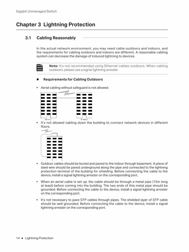
■ Aerial cabling without safeguard is not allowed.
■ It’s not allowed cabling down the building to connect network devices in different floors.
■ Outdoor cables should be buried and paved to the indoor through basement. A piece of steel wire should be paved underground along the pipe and connected to the lightning protection terminal of the building for shielding. Before connecting the cable to the device, install a signal lightning arrester on the corresponding port.
■ When an aerial cable is set up, the cable should be through a metal pipe (15m long at least) before coming into the building. The two ends of this metal pipe should be grounded. Before connecting the cable to the device, install a signal lightning arrester on the corresponding port.
■ It’s not necessary to pave STP cables through pipes. The shielded layer of STP cable should be well grounded. Before connecting the cable to the device, install a signal lightning arrester on the corresponding port.
Gigabit Unmanaged Switch
15Lightning Protection
■ Requirements for Cabling Indoors
When cabling indoors, keep a certain distance away from the devices that may cause high-frequency interferences, such as down-conductor cable, powerline, power transformer and electromotor.
■ The main cable should be paved in the metal raceway of the access shaft. When cabling, keep the loop area formed by the cable itself as small as possible.
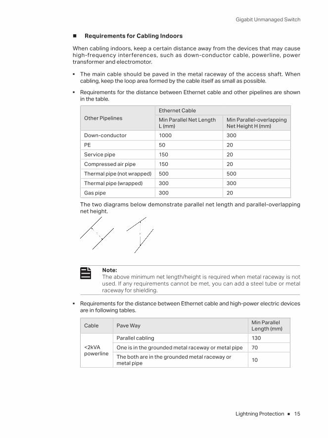
■ Requirements for the distance between Ethernet cable and other pipelines are shown in the table.
Other PipelinesEthernet CableMin Parallel Net Length L (mm)
Min Parallel-overlapping Net Height H (mm)
Down-conductor 1000 300
PE 50 20
Service pipe 150 20
Compressed air pipe 150 20
Thermal pipe (not wrapped) 500 500
Thermal pipe (wrapped) 300 300
Gas pipe 300 20
The two diagrams below demonstrate parallel net length and parallel-overlapping net height.
Note: The above minimum net length/height is required when metal raceway is not used. If any requirements cannot be met, you can add a steel tube or metal raceway for shielding.
■ Requirements for the distance between Ethernet cable and high-power electric devices are in following tables.
Cable Pave Way Min Parallel Length (mm)
<2kVA powerline
Parallel cabling 130
One is in the grounded metal raceway or metal pipe 70The both are in the grounded metal raceway or metal pipe 10
Gigabit Unmanaged Switch
16 Lightning Protection
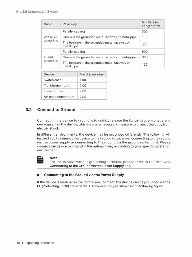
Cable Pave Way Min Parallel Length (mm)
2 to 5kVA powerline
Parallel cabling 300
One is in the grounded metal raceway or metal pipe 150The both are in the grounded metal raceway or metal pipe 80
>5kVA powerline
Parallel cabling 600
One is in the grounded metal raceway or metal pipe 300The both are in the grounded metal raceway or metal pipe 150
Device Min Distance (m)
Switch case 1.00
Transformer room 2.00
Elevator tower 2.00
Air-conditioner room 2.00
3.2 Connect to Ground
Connecting the device to ground is to quickly release the lightning over-voltage and over-current of the device, which is also a necessary measure to protect the body from electric shock.
In different environments, the device may be grounded differently. The following will instruct you to connect the device to the ground in two ways, connecting to the ground via the power supply or connecting to the ground via the grounding terminal. Please connect the device to ground in the optimum way according to your specific operation environment.
Note: For the device without grounding terminal, please refer to the f irst way Connecting to the Ground via the Power Supply only.
■ Connecting to the Ground via the Power Supply
If the device is installed in the normal environment, the device can be grounded via the PE (Protecting Earth) cable of the AC power supply as shown in the following figure.
Gigabit Unmanaged Switch
17Lightning Protection
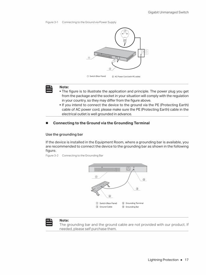
Figure 3-1 Connecting to the Ground via Power Supply
Switch (Rear Panel) AC Power Cord (with PE cable)
Note: ■ The figure is to illustrate the application and principle. The power plug you get from the package and the socket in your situation will comply with the regulation in your country, so they may differ from the figure above.
■ If you intend to connect the device to the ground via the PE (Protecting Earth) cable of AC power cord, please make sure the PE (Protecting Earth) cable in the electrical outlet is well grounded in advance.
■ Connecting to the Ground via the Grounding Terminal
Use the grounding bar
If the device is installed in the Equipment Room, where a grounding bar is available, you are recommended to connect the device to the grounding bar as shown in the following figure.Figure 3-2 Connecting to the Grounding Bar
Switch (Rear Panel)Ground Cable
Grounding Terminal
Grounding Bar
Note: The grounding bar and the ground cable are not provided with our product. If needed, please self purchase them.
Gigabit Unmanaged Switch
18 Lightning Protection
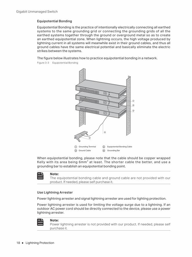
Equipotential Bonding
Equipotential Bonding is the practice of intentionally electrically connecting all earthed systems to the same grounding grid or connecting the grounding grids of all the earthed systems together through the ground or overground metal so as to create an earthed equipotential zone. When lightning occurs, the high voltage produced by lightning current in all systems will meanwhile exist in their ground cables, and thus all ground cables have the same electrical potential and basically eliminate the electric strikes between the systems.
The figure below illustrates how to practice equipotential bonding in a network.Figure 3-3 Equipotential Bonding
Grounding Terminal Equipotential Bonding Cable
Grounding Bar Ground Cable
When equipotential bonding, please note that the cable should be copper wrapped Kelly with its area being 6mm2 at least. The shorter cable the better, and use a grounding bar to establish an equipotential bonding point.
Note: The equipotential bonding cable and ground cable are not provided with our product. If needed, please self purchase it.
Use Lightning Arrester
Power lightning arrester and signal lightning arrester are used for lighting protection.
Power lightning arrester is used for limiting the voltage surge due to a lightning. If an outdoor AC power cord should be directly connected to the device, please use a power lightning arrester.
Note: Power lightning arrester is not provided with our product. If needed, please self purchase it.
Gigabit Unmanaged Switch
19Lightning Protection
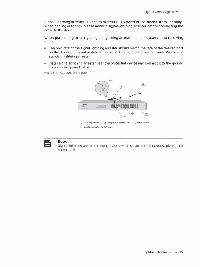
Signal lightning arrester is used to protect RJ45 ports of the device from lightning. When cabling outdoors, please install a signal lightning arrester before connecting the cable to the device.
When purchasing or using a signal lightning arrester, please observe the following rules:
■ The port rate of the signal lightning arrester should match the rate of the desired port on the device. If it is not matched, this signal lighting arrester will not work. Purchase a standard lightning arrester.
■ Install signal lightning arrester near the protected device and connect it to the ground via a shorter ground cable.
Figure 3-4 Use Lightning Arrester
Ethernet CableEquipotential Bonding CableGrounding Terminal
Signal Lightning Arrester Device
Note: Signal lightning arrester is not provided with our product. If needed, please self purchase it.
Gigabit Unmanaged Switch
20 Connection
Chapter 4 Connection
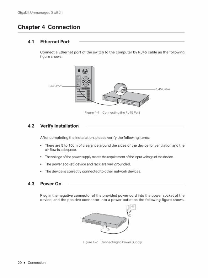
4.1 Ethernet Port
Connect a Ethernet port of the switch to the computer by RJ45 cable as the following figure shows.
RJ45 PortRJ45 Cable
Figure 4-1 Connecting the RJ45 Port
4.2 Verify Installation
After completing the installation, please verify the following items:
■ There are 5 to 10cm of clearance around the sides of the device for ventilation and the air flow is adequate.
■ The voltage of the power supply meets the requirement of the input voltage of the device.
■ The power socket, device and rack are well grounded.
■ The device is correctly connected to other network devices.
4.3 Power On
Plug in the negative connector of the provided power cord into the power socket of the device, and the positive connector into a power outlet as the following figure shows.
Figure 4-2 Connecting to Power Supply
Gigabit Unmanaged Switch
21Connection
Note: The figure is to illustrate the application and principle. The power plug you get from the package and the socket in your situation will comply with the regulation in your country, so they may differ from the figure above.
4.4 Initialization
For TL-SG1048/TL-SG1024/TL-SG1024D/TL-SG1016/TL-SG1016D/TL-SG1008: After the device is powered on, it begins the Power-On Self-Test. A series of tests run automatically to ensure the device functions properly. During this time, its LED indicators will respond as follows:
■ All of the LED indicators will flash momentarily for one second, which represents a resetting of the system.
■ The Power LED indicator will light up.
For TL-SG1008PE:The LED indicators for TL-SG1008PE are classified into two parts:
the LEDs indicating switch status including Power LED, Link/Act LEDs and 1000Mbps LEDs; the LEDs indicating PSE status, including PoE MAX LED and PoE Status LEDs.
After the device is powered on, it begins the Power-On Self-Test. A series of tests run automatically to ensure the device functions properly. During this time, its LED indicators will respond as follows:
■ All of the LEDs indicating swith status will flash momentarily for one second, which represents a resetting of the switch system. The PoE MAX LED will keep on for approximately ten seconds, representing a resetting of the PSE system. Take note that the PoE Status LEDs won't light up during this period.
■ The Power LED indicator will light up.
Gigabit Unmanaged Switch
22 Appendix A Troubleshooting
Appendix A TroubleshootingQ1. Why is the Power LED not lit?
The Power LED should be lit up when the power system works normally. If the Power LED worked abnormally, please try the following:
1. Make sure that the power cable is connected properly, and the power contact is normal.2. Make sure the voltage of the power supply meets the requirement of the input voltage of
the switch.
Q2. Why is the Link/Act LED not lit while a device is connected to the corresponding port?
Please try the following:
1. Make sure that the cable connectors are firmly plugged into the switch and the device.2. Make sure the connected device is turned on and working normally.3. The cable must be less than 100 meters long (328 feet).
■ For more troubleshooting help, go to: http://www.tp-link.com/en/support/faq
■ To download the latest Firmware, Driver, Utility and User Guide, go to: http://www.tp-link.com/en/support/download
Gigabit Unmanaged Switch
23Appendix B Specifications
Appendix B Specifications
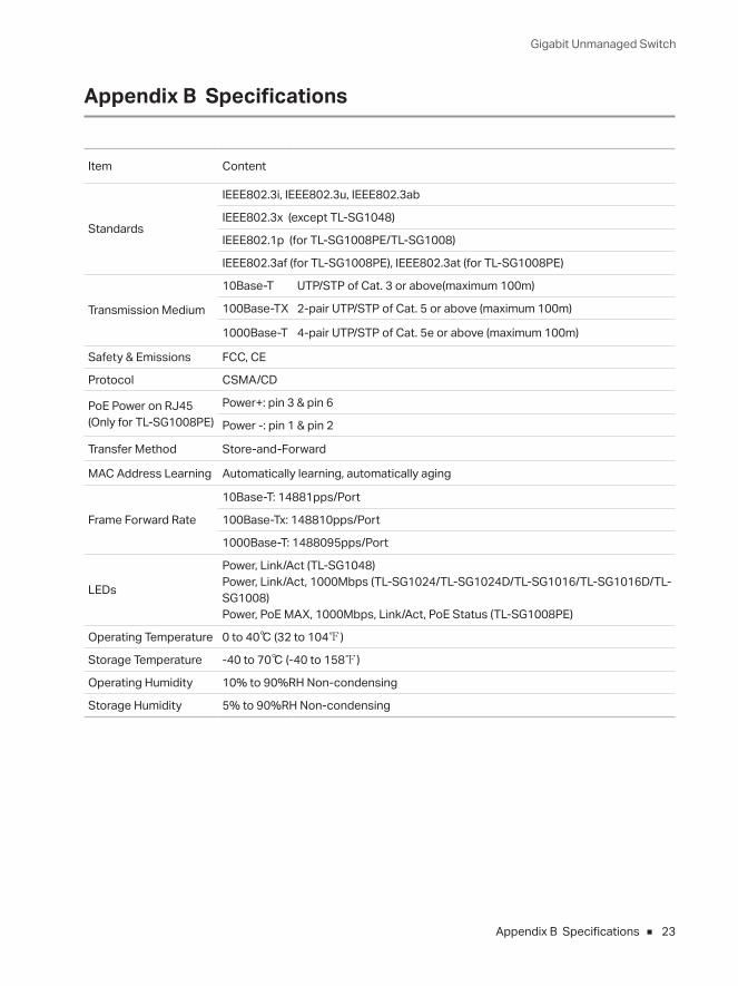
Item Content
Standards
IEEE802.3i, IEEE802.3u, IEEE802.3ab
IEEE802.3x (except TL-SG1048)
IEEE802.1p (for TL-SG1008PE/TL-SG1008)
IEEE802.3af (for TL-SG1008PE), IEEE802.3at (for TL-SG1008PE)
Transmission Medium
10Base-T UTP/STP of Cat. 3 or above(maximum 100m)
100Base-TX 2-pair UTP/STP of Cat. 5 or above (maximum 100m)
1000Base-T 4-pair UTP/STP of Cat. 5e or above (maximum 100m)
Safety & Emissions FCC, CE
Protocol CSMA/CD
PoE Power on RJ45(Only for TL-SG1008PE)
Power+: pin 3 & pin 6
Power -: pin 1 & pin 2
Transfer Method Store-and-Forward
MAC Address Learning Automatically learning, automatically aging
Frame Forward Rate
10Base-T: 14881pps/Port
100Base-Tx: 148810pps/Port
1000Base-T: 1488095pps/Port
LEDs
Power, Link/Act (TL-SG1048)Power, Link/Act, 1000Mbps (TL-SG1024/TL-SG1024D/TL-SG1016/TL-SG1016D/TL-SG1008)Power, PoE MAX, 1000Mbps, Link/Act, PoE Status (TL-SG1008PE)
Operating Temperature 0 to 40℃ (32 to 104℉)
Storage Temperature -40 to 70℃ (-40 to 158℉)
Operating Humidity 10% to 90%RH Non-condensing
Storage Humidity 5% to 90%RH Non-condensing

FCC STATEMENTThis equipment has been tested and found to comply with the limits for a Class A digital device, pursuant to part 15 of the FCC Rules. These limits are designed to provide reasonable protection against harmful interference when the equipment is operated in a commercial environment. This equipment generates, uses, and can radiate radio frequency energy and, if not installed and used in accordance with the instruction manual, may cause harmful interference to radio communications. Operation of this equipment in a residential area is likely to cause harmful interference in which case the user will be required to correct the interference at his own expense.
This device complies with part 15 of the FCC Rules. Operation is subject to the following two conditions:
• This device may not cause harmful interference.
• This device must accept any interference received, including interference that may cause undesired operation.
Any changes or modifications not expressly approved by the party responsible for compliance could void the user’s authority to operate the equipment.
CE Mark Warning
This is a Class A product. In a domestic environment, this product may cause radio interference, in which case the user may be required to take adequate measures.
Продукт сертифіковано згідно с правилами системи УкрСЕПРО на відповідність вимогам нормативних документів та вимогам, що передбачені чинними законодавчими актами України.
Safety Information• When product has power button, the power button is one of the way to shut off the product; when
there is no power button, the only way to completely shut off power is to disconnect the product or the power adapter from the power source.
• Don’t disassemble the product, or make repairs yourself. You run the risk of electric shock and voiding the limited warranty. If you need service, please contact us.
• Avoid water and wet locations.

BSMI Notice安全諮詢及注意事項
• 請使用原裝電源供應器或只能按照本產品注明的電源類型使用本產品。
• 清潔本產品之前請先拔掉電源線。請勿使用液體、噴霧清潔劑或濕布進行清潔。
• 注意防潮,請勿將水或其他液體潑灑到本產品上。
• 插槽與開口供通風使用,以確保本產品的操作可靠並防止過熱,請勿堵塞或覆蓋開口。
• 請勿將本產品置放於靠近熱源的地方。除非有正常的通風,否則不可放在密閉位置中。
• 請不要私自打開機殼,不要嘗試自行維修本產品,請由授權的專業人士進行此項工作。
• 此為甲類資訊技術設備,于居住環境中使用時,可能會造成射頻擾動,在此種情況下,使用者會被要求採取某
些適當的對策。
Industry Canada StatementCAN ICES-3 (A)/NMB-3(A)
Explanation of the symbols on the product label
Symbol Explanation
AC voltage
Indoor use only
RECYCLING
This product bears the selective sorting symbol for Waste electrical and electronic equipment (WEEE). This means that this product must be handled pursuant to European directive 2012/19/EU in order to be recycled or dismantled to minimize its impact on the environment.
User has the choice to give his product to a competent recycling organization or to the retailer when he buys a new electrical or electronic equipment.
この装置は、クラスA情報技術装置です。この装置を家庭環境で使用すると電波妨害を引き起こすことがあります。この場合には使用者が適切な対策を講ずるよう要求されることがあります。 VCCI-A


© 2017 TP-Link 7106507326 REV12.0.2
For technical support and other information, please visit http://www.tp-link.com/support, or simply scan the QR code.