Embed Size (px)
Citation preview

TH 1233 (HANDWHEELS) / TL 1233 (LEVERS)THREE HOLE BASIN MIXER
INSTALLATION GUIDE

102mm
180mm minimum - 280mm maximum
79mm
190mm maximum
Ø21mmØ26mm 43mmmaximum
50mmmaximum
G½
Ø60mm
Ø52mmØ43mm
Levermodel
Handwheelmodel
HOT COLD
80mm
2
Not to scale
DIMENSIONS

170mm
126mm
47mm
132mm
220mm maximum
50mm maximum
G 1¼
3
DIMENSIONS
Not to scale

It is recommended that the flow valves and hoses are installed as shown
4
FLEXIBLE HOSE CONNECTIONS
10 20 30 40
3.0
2.0
1.0
50
Flow (Litres/minute)
Stat
ic P
ress
ure
(Bar
)
4 5
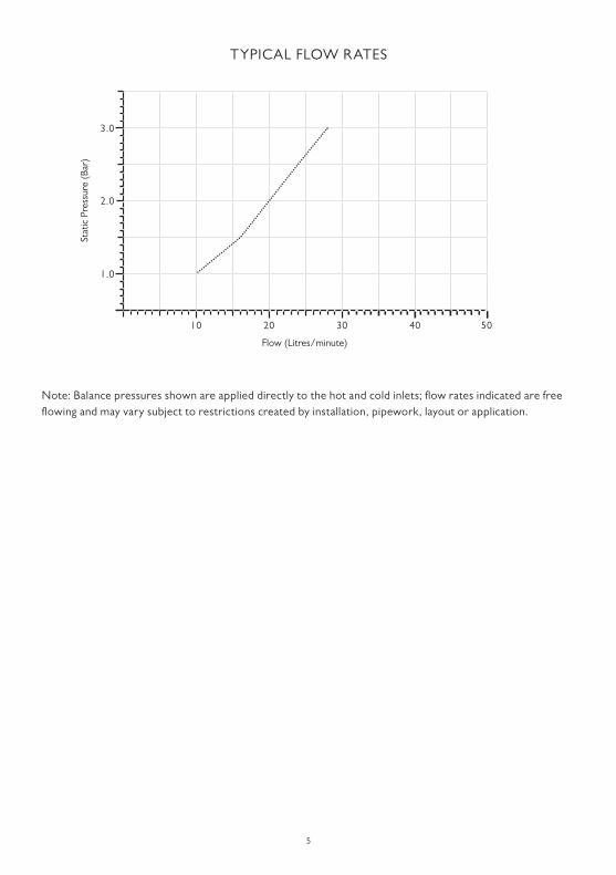
TYPICAL FLOW RATES
Note: Balance pressures shown are applied directly to the hot and cold inlets; flow rates indicated are free flowing and may vary subject to restrictions created by installation, pipework, layout or application.

6
IMPORTANT INFORMATION
Professional installationWe recommend that our products are fitted bya fully qualified professional plumber. They should be installed correctly and in accordance with all local water regulations and the system protected by non-return valves (not supplied). All products should be accessible for routine servicing.
Suits all systemsThis Lefroy Brooks product is potentially suitable for every possible application, type of boiler and water supply pressure. However, if your supply pressure is below 1 bar it is advisable to fit a water pump. For systems with combination boilers, it is not advisable to fit pumps (refer to boiler manufacturer).
Supply connectionsThe hot and cold water supplies should be connected using suitable ½" connectors.
Supply temperature safety noticeTo comply with local building regulations, current legislation, relevant standards and codes of practice a thermostatic mixing valve (TMV) should be fitted (not supplied) to the hot supply. This will restrict the temperature to a safe working maximum temperature. Maximum allowed temperatures vary subject to type of installation or specification of building.
Balancing flowIf there is a significant difference in water pressures between hot & cold supplies, we recommend an in-line flow suppressor/regulator (not supplied) be fitted. This should be fitted to whichever has the greater flow rate, in an accessible position close to the valve. Do not fit the flow suppressor/regulatorat the spout as this will increase the pressure in the flexible hoses.
Water qualityIn hard water areas, a suitable water treatment system should be provided to prevent limescale deposits (calcium deposits) which may effect the long term performance of the ceramic cartridges. Exterior surfaces should be gently wiped with a dry soft cloth after use to minimise water stains and limescale deposits.
Flushing systemIt is most important to flush out all pipework thoroughly before connecting the product. This is the single most common cause of ceramic cartridge failure.
ServicingAll serviceable parts are available to maintain your Lefroy Brooks product.

Mounting surface
Control rod link
Control rod
Ball joint retainer
Ball joint washerBody
Rubber seal
Basin
Foam seal
Plug housing
Plug
Adjustment screw
Washer
Backnut
Four way connector
‘O’ ring
Reducing bush
Nut
Pop-up rod
Pop-up rod
Spout
7
PARTS IDENTIFICATION

Washer
Backnut
Four way connector
‘O’ ring
Reducing bush
Nut
8
SPOUT INSTALLATION
1 Where necessary drill a Ø23–25mm hole in the mounting surface.
2 Unscrew (clockwise) and remove the nut from the bottom of the four way connector (A).
3 Remove the reducing bush from the bottom of the four way connector (B).
4 There is a short length of copper tube at the top of the four way connector. Unscrew (clockwise) the nut at the top of the copper tube (C). Gently pull the four way connector assembly clear of the threaded tail. Be careful not to damage the white tube that runs through the threaded tail. There is an ‘o’ ring in the bottom of the four way connector, attached to the white tube; this will drop out when removing the four way connector.
5 Unscrew (clockwise) and remove the backnut and washer from the threaded tail (D).
A
B
C
D

Washer
Backnut
9
6 Pass the threaded tail of the spout through the hole in the mounting surface (E). Align the spout.
7 Locate the washer onto the threaded tail (F).
8 Screw the backnut (counter clockwise) onto the threaded tail and tighten to secure the spout (G).
SPOUT INSTALLATION
F
E
G

‘O’ ring
Four way connector
Reducing bush
Nut
Locate the ‘o’ ring into the four wayconnector before inserting the reducingbush and tightening the compression nut.
‘O’ ring
Reducing bush
NutDo not overtighten nut.
10
9 Locate the four way connector and tighten the upper locking nut (H). Ensure that the ‘o’ ring is located into the four way connector (J) before inserting the reducing bush. Tighten the compression nut.
H
J
SPOUT INSTALLATION
11
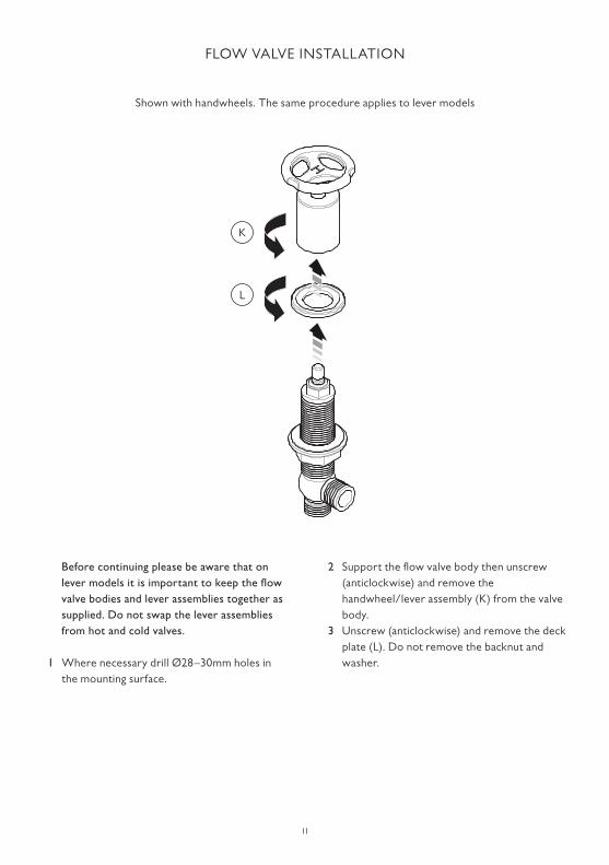
FLOW VALVE INSTALLATION
Before continuing please be aware that on lever models it is important to keep the flow valve bodies and lever assemblies together as supplied. Do not swap the lever assemblies from hot and cold valves.
1 Where necessary drill Ø28–30mm holes in the mounting surface.
2 Support the flow valve body then unscrew (anticlockwise) and remove the handwheel/lever assembly (K) from the valve body.
3 Unscrew (anticlockwise) and remove the deck plate (L). Do not remove the backnut and washer.
K
L
Shown with handwheels. The same procedure applies to lever models

Deck plate belowceramic cartridge
Ceramic cartridge
Splines
12
FLOW VALVE INSTALLATION
4 Locate the flow valve through the hole in the mounting surface (M).
5 Screw the deck plate onto the top of the flow valve, beyond the level of the ceramic cartridge (N).
6 On handwheel models rotate the splines on top of the ceramic cartridges so that they are in the fully clockwise position. On lever models rotate the splines on top of the ‘hot’ ceramic cartridge so that they are in the fully clockwise position and the splines on top of the ‘cold’ ceramic cartridge so that they are in the fully counter clockwise position. The handwheels/levers can be loosely located to achieve this.
7 Rotate the flow valve body so that the side outlet port is facing the required direction for connection.
M N

Splines
Lateral movement
Rotate the shroud untillateral handwheel/levermovement is eliminated
13
FLOW VALVE INSTALLATION
8 With the handwheel/lever ‘H’ or ‘C’ aligned, locate the handwheel/lever assembly onto the splines of the cartridge (P). Rotate the shroud of the handwheel/lever assembly in a clockwise direction until lateral movement of the handwheel/lever is eliminated (Q). DO NOT tighten the handwheel/lever assembly in place as this may damage the ceramic cartridge. The aim is to simply rotate the handwheel/lever assembly shroud until the handwheel/lever no longer has any lateral/up and down movement.
9 With the lateral movement adjustment completed, rotate the deck plate counter clockwise to meet the handwheel/lever assembly, leaving no gap between them (R).
10 Ensure that the handwheel/lever alignment is as required before securing the flow valve in place. The flow valve can be rotated to correct any small alignment issues. Tighten the backnut to secure the flow valve in place (S).
P
QR
S
Shown with handwheels. The same procedure applies to lever models

Control rod link
Control rod
Ball joint retainer
Ball joint washer
Body
Rubber seal
Basin
Foam seal
Plug housing
Plug
Adjustment screw
Pop-up rod
Logo alignment
Spout
14
POP-UP WASTE INSTALLATION
1 Insert the pop-up waste lever into the hole in the top of the spout.
2 Assemble the pop-up waste to the basin with the foam seal on top of the mounting surface and the rubber seal below. The wide diameter of the rubber seal sits on top of the waste body. Tighten by hand.
3 Place the control rod link onto the rod of the pop-up waste lever, then feed the control rod through. Locate the short end of the control rod, the one with the ball, into the waste and secure by screwing the ball joint retainer in place. Do not over tighten.
4 Gently clamp the control rod link to the pop-up waste lever rod. Test the operation of the pop-up waste and if satisfactory fully tighten the control rod link to the pop-up waste lever rod. If not satisfactory then make adjustments to the control rod link as required. If the operation is stiff simply loosen the ball joint retainer as required.
5 Connect the flexible hoses to the basin mixer.6 Connect the hot and cold water supplies to
the bottom of the appropriate flexible hoses. Turn on the water supplies and check for leaks. Check the operation of the basin mixer.

15
SERVICING – CARTRIDGE REPLACEMENT
Before continuing please ensure that the water supplies have been isolated and drained where necessary.
1 To remove the ceramic cartridge(s), unscrew (counter clockwise) and remove the handwheel/lever assembly/assemblies (U).
2 Support the flow valve body then unscrew (counter clockwise) and remove the ceramic cartridge(s) using a 17mm spanner (V).
3 Assemble in the reverse order.4 Refer to point 8–10 in the ‘flow valve
installation’ section to ensure the handwheel/lever assembly/assemblies is/are installed correctly.
U
V
Shown with handwheels. The same procedure applies to lever models

Aerator
Washer
Aerator cover
16
SERVICING – CLEANING THE SPOUT AERATOR
1 There is an aerator located in the end of the spout. To remove the aerator unscrew and remove the aerator cover in a clockwise direction.
2 The aerator can be cleaned in warm soapy water.
3 Assemble in the reverse order.

17
FAULT FINDING
The hot/cold flow valves are turned off but the spout drips continuously.• Replace the ceramic cartridge(s). See below for spare part numbers and the ‘servicing – cartridge
replacement’ section
Water flow from the spout is reduced.• Debris from the water supply may be causing restriction at the aerator located in the end of the spout.
The aerator can be removed for cleaning (see ‘servicing – cleaning the spout aerator’ section)• Check that there are no tight bends in the flexible hoses
Noisy operation• Check that there are no tight bends in the flexible hoses• Reduce water pressure
Leaks from underside of basin• Flexible hose joints not tight• ‘O’ ring inside of four way connector damaged• Reducing bush in bottom of four way connector fitted upside down Pop-up rod movement is stiff/loose• Adjust the ball joint retainer where the horizontal control rod fits into the waste assembly
(see ‘parts identification’ or ‘pop-up waste installation’ section)

18
REPLACEMENT PARTS
PHL034 – Pair of ½" x ½ turn ceramic cartridges for handwheels (clockwise closing)PHL038 – Single ½" x ½ turn ceramic cartridge for handwheels (clockwise closing – left side).PHL039 – Single ½" x ½ turn ceramic cartridge for handwheels (clockwise closing – right side).
PHL035 – Pair of ½" x ¼ turn ceramic cartridges for levers (one clockwise closing (left side) and one counter clockwise closing (right side)).PHL040 – Single ½" x ¼ turn ceramic cartridge for lever (clockwise closing – left side).PHL041 – Single ½" x ¼ turn ceramic cartridge for lever (counter clockwise closing – right side).
PSH022 – Pair of replacement braided flexible hoses.
PPW041 – Pop up rod (standard length of 330mm)PPW042 – Pop up rod (longer length of 500mm)PPW016 – Horizontal rod and ball (standard length of 200mm)PPW017 – Horizontal rod and ball (longer length of 500mm)
PFR016 – Aerator and Aerator washerPSH099 – Aerator sleeve


Whilst every effort is made to ensure the accuracy of these, they are subject to change without notice as part of the company’s product development process. The use of trademarks, product design
and artwork is subject to licence or agreement with LBIP Ltd. The design registrations, trademark registrations and copyrights are protected by law and the use or reproduction outside the terms of an agreement is prohibited. The right to modify designs and dimensions is reserved. LBIP Ltd is a member of ACID (Anti Copying in Design).
© LBIP Ltd 2016
CUSTOMER SUPPORT
+44 (0)1992 708 316
L E F R OY B R O O K S . C O . U K
20.065.234A / JUNE 2016


![[ ADGAS_Co Module_04 ] Pipework](https://img.pdfslide.us/doc/110x75/543fef1cb1af9f560a8b4ad0/-adgasco-module04-pipework.jpg)