Embed Size (px)
Citation preview
INSTALLATION GUIDE FOR AVALON FOLDING ARM AWNING IG 30.03
JPM Blinds & Awnings Installation Guide Revision: B 11th September 2013 Page 1 of 14
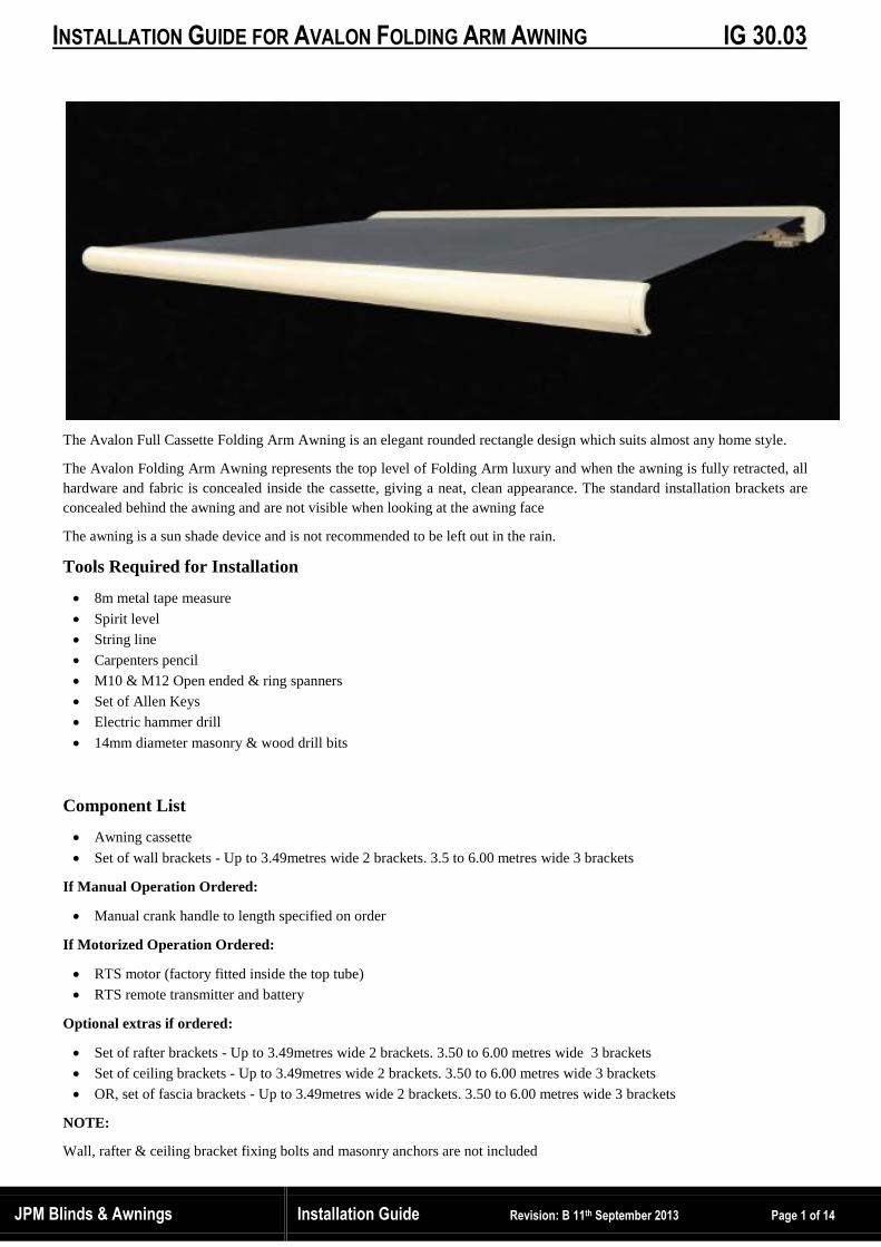
The Avalon Full Cassette Folding Arm Awning is an elegant rounded rectangle design which suits almost any home style.
The Avalon Folding Arm Awning represents the top level of Folding Arm luxury and when the awning is fully retracted, all
hardware and fabric is concealed inside the cassette, giving a neat, clean appearance. The standard installation brackets are
concealed behind the awning and are not visible when looking at the awning face
The awning is a sun shade device and is not recommended to be left out in the rain.
Tools Required for Installation
8m metal tape measure
Spirit level
String line
Carpenters pencil
M10 & M12 Open ended & ring spanners
Set of Allen Keys
Electric hammer drill
14mm diameter masonry & wood drill bits
Component List
Awning cassette
Set of wall brackets - Up to 3.49metres wide 2 brackets. 3.5 to 6.00 metres wide 3 brackets
If Manual Operation Ordered:
Manual crank handle to length specified on order
If Motorized Operation Ordered:
RTS motor (factory fitted inside the top tube)
RTS remote transmitter and battery
Optional extras if ordered:
Set of rafter brackets - Up to 3.49metres wide 2 brackets. 3.50 to 6.00 metres wide 3 brackets
Set of ceiling brackets - Up to 3.49metres wide 2 brackets. 3.50 to 6.00 metres wide 3 brackets
OR, set of fascia brackets - Up to 3.49metres wide 2 brackets. 3.50 to 6.00 metres wide 3 brackets
NOTE:
Wall, rafter & ceiling bracket fixing bolts and masonry anchors are not included

INSTALLATION GUIDE FOR AVALON FOLDING ARM AWNING IG 30.03
JPM Blinds & Awnings Installation Guide Revision: B 11th September 2013 Page 2 of 14
Bracket Installation Basics
IMPORTANT: ALL TYPES OF INSTALLATION BRACKETS MUST BE MOUNTED ABSOLUTELY ALIGNED, IN
BOTH HORIZONTAL & PERPENDICULAR PLANES, TO PROVIDE A FLAT SURFACE TO MOUNT THE
CASSETTE. IF THE BRACKETS ARE NOT ALIGNED THE CASSETTE HOUSING WILL BOW AND THE AWNING
WILL NOT FULLY CLOSE
Positioning of Fixing Brackets
IMPORTANT - The 2 end brackets must be within 50mm of the arm brackets otherwise the forces transmitted through the
arm brackets may twist the awning cassette & affect closing
Position fixing brackets as marked by labels on the awning which state “INSTAL SUPPORT BRACKETS HERE”
If the awning is over 3.5 metres wide a centre fixing bracket is supplied
All brackets specified must be installed for safety reasons
Bracket Fixings
Wall brackets, ceiling brackets and rafter brackets must be solidly anchored to a substantial surface. Use appropriate masonry
anchors to firmly secure mounting brackets. Information on the pull-out forces is available in Fact Card No. FS 20.3
Check for Obstructions
Check for any obstructions that would interfere with installation and operation of the awning: e.g. electrical power lines,
water pipes, down pipes, light fittings, opening doors façade features or clothes lines
Rafter or Fascia Bracket Installations
If rafter or fascia brackets have been specified then it will be necessary to have
access to remove sections of the roofing to gain access to fit brackets to roof
trusses. At the time of check measuring the type of roofing & ability to remove
sections of the roof, to fit rafter or fascia brackets, should be checked. ClipLok
type steel roofing cannot be removed
Where the awning is mounted using rafter or fascia brackets and roof trusses are
not adjacent to arm bracket positions then add additional roofing timbers and
bracing to fix brackets in the correct position. Installation brackets must be within
50mm of arm brackets, to prevent twisting of the awning cassette.
Bracket < 50mm
Bracket > 50mm
Cliplok Steel Roofing – cannot be
removed to gain access to roof trusses

INSTALLATION GUIDE FOR AVALON FOLDING ARM AWNING IG 30.03
JPM Blinds & Awnings Installation Guide Revision: B 11th September 2013 Page 3 of 14

INSTALLATION GUIDE FOR AVALON FOLDING ARM AWNING IG 30.03
JPM Blinds & Awnings Installation Guide Revision: B 11th September 2013 Page 4 of 14
Wall Bracket Installation
For structural strength and safety there shall be a minimum of 7 courses of bricks above the awning brackets fixed to the
wall. If there are not 7 courses of bricks above the brackets then install special spreader brackets, to enable bracket fixing
below 7 courses of bricks, or consider using fascia or rafter brackets
Sandwich type foam walls, aerated cement or hollow block walls are not suitable for mounting folding arm awning brackets
If the mounting structure is concrete, solid, aged, hollow or soft brick then Ramset Chemset 101 Anchors with Chemset M12
Studs or similar are recommended. Drill, thoroughly clean holes & allow cure time as per anchor manufacturer’s instructions
If the wall is timber then check and fit timber battening or bracing, where required, so that the cassette cannot flex or twist
For brackets mounted onto timber beams 12mm dia. x 75mm minimum length galvanized steel coach bolts are recommended
STEP 1(W) - Install Outer Brackets to Coincide with Arm Brackets
Mark out, check holes are level & in alignment and drill fixing holes for the 2 outside brackets. The position of arm brackets
is indicated by labels on the outside of the cassette which state “INSTAL SUPPORT BRACKETS HERE”
STEP 2 (W) Install Centre Bracket - for Awnings Over 4 metres Wide
Fit a string line to each end bracket & use to perfectly align & level all brackets
STEP 3 (W) - Align all Brackets, Shim & Tighten Bolts
Allow Chemset fixings to fully cure, as per manufacturer’s instructions, before tightening
Align horizontally using a string line to check the wall is flat and vertically using a spirit level to ensure perfect alignment.
If the wall is not perfectly flat then pack (shim) brackets so they are in perfect alignment & level
Pack brackets in perfect alignment & level
Align Align
Align
INSTALLATION GUIDE FOR AVALON FOLDING ARM AWNING IG 30.03
JPM Blinds & Awnings Installation Guide Revision: B 11th September 2013 Page 5 of 14
Ceiling Bracket Installation
If the mounting structure is concrete, Ramset Chemset 101 Anchors with Chemset M12 Studs (use anti drip retaining collars)
or similar are recommended. Drill, thoroughly clean holes & allow cure time as per manufacturer’s instructions
STEP 1 (C) - Install Outer Ceiling Brackets to Coincide with Arm Brackets
Mark out, check holes are level & in alignment and drill fixing holes for the 2 outside brackets. The position of arm brackets
is indicated by labels on the outside of the cassette which state “INSTAL SUPPORT BRACKETS HERE”
STEP 2 (C) - Install Centre Ceiling Bracket - for Awnings Over 4 metres Wide
Where 3 or more brackets are required use a string line to perfectly align & level brackets
STEP 3 (C) - Align all Ceiling Brackets & Tighten Bolts
Allow Chemset fixings to fully cure, as per manufacturer’s instructions, before tightening
Tighten ceiling brackets to ceiling bolt connections & again check alignment
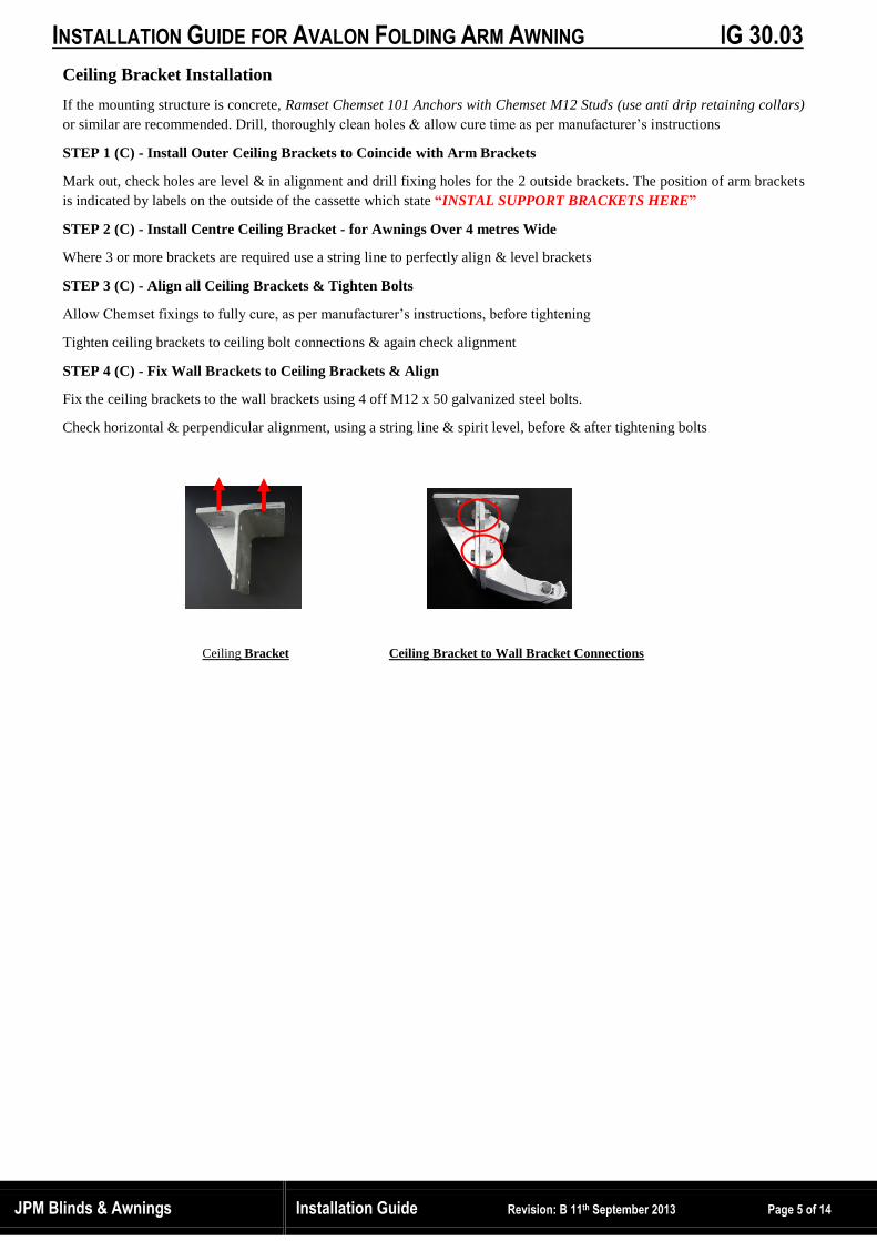
STEP 4 (C) - Fix Wall Brackets to Ceiling Brackets & Align
Fix the ceiling brackets to the wall brackets using 4 off M12 x 50 galvanized steel bolts.
Check horizontal & perpendicular alignment, using a string line & spirit level, before & after tightening bolts
Ceiling Bracket Ceiling Bracket to Wall Bracket Connections

INSTALLATION GUIDE FOR AVALON FOLDING ARM AWNING IG 30.03
JPM Blinds & Awnings Installation Guide Revision: B 11th September 2013 Page 6 of 14
Rafter Bracket Installation
STEP 1 (R) - Install Outer Rafter Brackets to Coincide with Arm Brackets
Lift the roofing material carefully to avoid any damage. Note Cliplok roofing cannot be removed
The brackets MUST be installed within 50mm from the arm brackets to transmit the arm forces back into the building
structure or the awning cassette may twist & not fully close. The position of arm brackets is indicated by labels on the outside
of the cassette which state “INSTAL SUPPORT BRACKETS HERE”
Check the rafters for their material condition and for sufficient stability.
Add additional roofing timbers and bracing if roof rafters are not adjacent to arm bracket positions
Adjust the rafter brackets and clamp to the rafter. Use the rafter bracket holes as a jig and drill minimum of 3 x 14mm
diameter holes through the rafter beam.
Attach the bracket to the beam using 3 – M12 x 60mm long galvanized steel bolts, nuts and washers, or size to suit beam
thickness (not supplied)
STEP 2 (R) - Install Centre Rafter Bracket - for Awnings Over 4 metres Wide
Where 3 or more brackets are required use a string line to perfectly align & level brackets
STEP 3 (R) - Align all Rafter Brackets & Tighten Bolts
Check the brackets on rafters are level & align horizontally using a string line and vertically using a spirit level to ensure
perfect alignment.
STEP 4 (R) - Fix Wall + Ceiling Brackets to Rafter Brackets
Fix the ceiling bracket to the rafter bracket using 4 off M12 x 50 galvanized steel bolts.
Align horizontally and vertically using a string line and spirit level to ensure perfect alignment. Check the brackets are level.
Fix the wall bracket to the ceiling bracket using 4 off M12 x 30mm long galvanized bolts, nuts & washers
Fix the wall and ceiling bracket assembly onto the rafter bracket using 4 – M12 x 30mm long galvanized bolts, nuts &
washers
Check all brackets are on one level both horizontally and vertically!
Adjust & shim (pack) level where required so they are in perfect alignment & securely tighten all bolts
Re-fit roofing material & check fully secured
Rafter Bracket Fixings Ceiling Bracket to Wall Bracket Connection
Ceiling / Wall Bracket to
Rafter Bracket Assembly

INSTALLATION GUIDE FOR AVALON FOLDING ARM AWNING IG 30.03
JPM Blinds & Awnings Installation Guide Revision: B 11th September 2013 Page 7 of 14
Fascia Bracket Installation
STEP 1 (R) - Install Outer Fascia Brackets to Coincide with Arm Brackets
Lift the roofing material carefully to avoid any damage. Note Cliplok cannot be removed
The most common roof pitch angles are 22 deg and 30 deg. Check angle of roof & angle of fascia brackets will fit.
The brackets MUST be installed within 50mm from the arm brackets to transmit the arm forces back into the building
structure or the awning cassette may twist & not fully close. The “INSTAL SUPPORT BRACKETS HERE”
Check the roof trusses for their material condition and for sufficient stability.
Measure out position for awning bracket and mark position for fascia brackets adjacent to roof trusses
Add additional roofing timbers and bracing if roof trusses are not adjacent to arm bracket positions
Drill/cut 50 x 12 slots through fascia board and fix fascia bracket to the timber truss using 3 off M12 x 60long galvanized
bolts, nuts & washers, or size to suit beam thickness (not supplied)
Adjust the Fascia brackets and clamp to the roof trusses. Use the Fascia bracket holes as a jig and drill minimum of 3 x
14mm diameter holes through the timber roof truss.
Attach the bracket to the timber truss using 3 – M12 x 60mm long galvanized steel bolts, nuts and washers
STEP 2 (R) - Install Centre Fascia Bracket - for Awnings Over 4 metres Wide
Where 3 or more brackets are required use a string line to perfectly align & level brackets
STEP 3 (R) - Align all Fascia Brackets & Tighten Bolts
Check the fascia brackets are level & align horizontally using a string line and vertically using a spirit level to ensure perfect
alignment.
STEP 4 (R) - Fix Wall Brackets to Fascia Brackets
Fix the Wall bracket to the Fascia bracket using 4 off M12 x 30mm long galvanized bolts, nuts & washers
Align horizontally and vertically using a string line and spirit level to ensure perfect alignment. Check the brackets are level.
Check all brackets are on one level both horizontally and vertically!
Adjust & shim (pack) level where required so they are in perfect alignment & securely tighten all bolts
Re-fit roofing material & check fully secured
Fascia Bracket Wall Bracket Fixed to Fascia Bracket
INSTALLATION GUIDE FOR AVALON FOLDING ARM AWNING IG 30.03
JPM Blinds & Awnings Installation Guide Revision: B 11th September 2013 Page 8 of 14
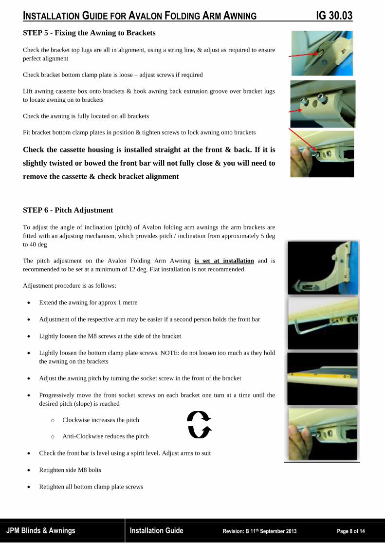
STEP 5 - Fixing the Awning to Brackets
Check the bracket top lugs are all in alignment, using a string line, & adjust as required to ensure
perfect alignment
Check bracket bottom clamp plate is loose – adjust screws if required
Lift awning cassette box onto brackets & hook awning back extrusion groove over bracket lugs
to locate awning on to brackets
Check the awning is fully located on all brackets
Fit bracket bottom clamp plates in position & tighten screws to lock awning onto brackets
Check the cassette housing is installed straight at the front & back. If it is
slightly twisted or bowed the front bar will not fully close & you will need to
remove the cassette & check bracket alignment
STEP 6 - Pitch Adjustment
To adjust the angle of inclination (pitch) of Avalon folding arm awnings the arm brackets are
fitted with an adjusting mechanism, which provides pitch / inclination from approximately 5 deg
to 40 deg
The pitch adjustment on the Avalon Folding Arm Awning is set at installation and is
recommended to be set at a minimum of 12 deg. Flat installation is not recommended.
Adjustment procedure is as follows:
Extend the awning for approx 1 metre
Adjustment of the respective arm may be easier if a second person holds the front bar
Lightly loosen the M8 screws at the side of the bracket
Lightly loosen the bottom clamp plate screws. NOTE: do not loosen too much as they hold
the awning on the brackets
Adjust the awning pitch by turning the socket screw in the front of the bracket
Progressively move the front socket screws on each bracket one turn at a time until the
desired pitch (slope) is reached
o Clockwise increases the pitch
o Anti-Clockwise reduces the pitch
Check the front bar is level using a spirit level. Adjust arms to suit
Retighten side M8 bolts
Retighten all bottom clamp plate screws

INSTALLATION GUIDE FOR AVALON FOLDING ARM AWNING IG 30.03
JPM Blinds & Awnings Installation Guide Revision: B 11th September 2013 Page 9 of 14
Electrical Installation of RTS ED Motor
Important Safety Note:
ELECTRICAL CONNECTION; Should always be carried out by an Authorised and Qualified Electrical Contractor
Follow the wiring diagram precisely. We cannot accept responsibility for damage that can result from improper installation.
Never connect directly parallel motors
Never simultaneously activate the drives with an UPWARDS and DOWNWARDS signal. Keep a break of approx. 0.5 seconds
between UPWARDS and the DOWNWARDS command (often neglected in Cbus systems)
Install motor cable from the underside of the motor with a loop in the cable to prevent water running down the cable into the
motor
IMPORTANT NOTE – When you turn on power to the motor the motor is in program mode. Do not press buttons for a short
period of time
Motor Wiring Diagram – 240 volts x single phase
Blue = Neutral
Brown = Live
Green/Yellow = Earth
DC 116 Wind Sensor Installation
Wind sensor should be installed with turbine blades horizontal
Mount on wall or eave to sense wind approaching open awning
Push to remove top cover over bracket.
Connect 2 wires in terminal block to 240 volts power
Centre connector is for neutral wire
Left or right connector is for direction to retract on activation
3 x 1.5mm2
(230 volts/50Hz)

INSTALLATION GUIDE FOR AVALON FOLDING ARM AWNING IG 30.03
JPM Blinds & Awnings Installation Guide Revision: B 11th September 2013 Page 10 of 14
RTS ED Motor Programming
The awning open & close limit settings are set by the factory and should not need adjusting. However should there be a need to
program the motor basic instructions are detailed below:
WARNING: After approximately 4 minutes of continuous operation, a built in thermal overload switch will
temporarily stop the awning motor to protect it from permanent damage due to overheating. The motor will resume
operating after approximately 20 minutes cooling period, at 20 deg C ambient temperature
Take care when programming or operating not to continuously operate the motor. A 3 metre projection awning takes 1
minute to open. If the motor is operated continuously it will trip out after opening & closing twice
IMPORTANT NOTE – When you turn on power to the motor the motor is in program mode. Do not randomly press buttons
for a short period of time
PAIR THE MOTOR TO THE REMOTE;
1. Turn on the power & within 4 seconds
2. Press the P2 button on the back of the remote TWICE
3. Press the UP button for anti-clockwise rotation
4. Press P2 button. Motor will emit a beep to confirm paired
REVERSE ROTATION
1. Press the P2 button on the back of the remote TWICE
2. Press and hold the DOWN button for clockwise rotation
SET OPEN LIMIT
1. Press P2 button on the back of the remote. Awning will jog up & down
2. Press close (UP) button & the motor will beep back
3. Press (DOWN) button & the awning will move open
4. Press the STOP button to confirm open limit position
5. Press the STOP button 5 times – awning will jog close & open to confirm setting then beep
SET THE CLOSED POSITION
1. Press the close (UP) button to fully close the awning
2. Press P2 button ONCE
3. Press the UP button ONCE
4. Press P2 button ONCE again. The motor will JOG then BEEP twice to confirm the setting is programmed
DC116 Wind Sensor Programming
Turn power on to awning motor & wind sensor
Press P2 button on the back of the remote TWICE
Within 6 seconds use a ball point pen to PRESS button on wind sensor
Wind sensor is now paired to the motor
3 positions to adjust sensitivity to suit. Recommend to set the wind sensitivity to the lowest setting on installation
With awning open spin the wind sensor turbine to test if the awning closes to confirm it is working correctly
Wind power grade (recommend initial setting at 1)
Sunlight grade (not required. Set to 0 = off)
Upward button
P2 programming button, to pair with motor
INSTALLATION GUIDE FOR AVALON FOLDING ARM AWNING IG 30.03
JPM Blinds & Awnings Installation Guide Revision: B 11th September 2013 Page 11 of 14
Commissioning & Functional Check
Before operation check the unit for visible damage. If the unit is damaged it should not be used, please consult authorized
specialist supplier immediately
We recommend the use of a test cable for the provisional connection to test the motor & check the awning operation and
motor set up
WARNING: After approximately 4 minutes of continuous operation, a built in thermal overload switch will
temporarily stop the awning motor to protect it from permanent damage due to overheating. The motor will resume
operating after approximately 20 minutes cooling period, at 20 deg C ambient temperature
Take care when programming or operating not to continuously operate the motor. A 3 metre projection awning
takes 1 minute to open. If the motor is operated continuously it will trip out after opening & closing twice
Extend and retract the unit in and out completely to check operation and limit settings. When extending the unit make sure
no one is in the operating radius or standing below the unit
After the first extending please visually check and test the awning bracket fixings for soundness and stability
Instruct the customer on the safe operation of the awning and hand them a copy of all Installation and Operation
Instructions
If the Avalon awning is over 4metres wide we will supply the awning factory fitted with a fabric top tube support cradle.
Check, & if necessary adjust the cradle, so it is positioned directly under the double thickness of a fabric seam
Open the awning and check the awning front bar is level using a spirit level. Adjust left hand or right hand pitch if necessary

INSTALLATION GUIDE FOR AVALON FOLDING ARM AWNING IG 30.03
JPM Blinds & Awnings Installation Guide Revision: B 11th September 2013 Page 12 of 14
General Information
Care and Maintenance Instructions
1. CLOSE YOUR AWNING in wet weather even if the fabric is wet. As soon as possible after rain, open the awning to allow
the fabric to dry. Like a tent fabric external awnings fabrics must not be left rolled up when wet
2. Periodically (suggest monthly when in use) hose down the cover and allow to dry. Also wash the frame. (Take special care
not to wet the motor & electric cable for motorized awnings)
Removal of salt residue in ocean proximity is essential
Removal of mould (which starts to grow in dust and bird droppings) on the fabric prolong fabric life
Check the mechanical parts of your awning for visible damage. Do not use the awning if any damage is found
Apply a light coating of “SILICONE” SPRAY to all frame joints and cables. This is particularly important in high
corrosion areas near the ocean. (Spray lubricants like WD-40 are NOT suitable).
3. Remove wet or embedded stains with care - Use diluted washing liquid in warm water and sponge fabric clean with a damp
cloth (avoid rubbing the stain). In all cases, the cleaning process should first be tested in an inconspicuous area.
4. DO NOT wash the fabric with strong detergents or bleaches Many of our fabrics are impregnated with mould & water
repelling agents, however, under certain conditions; even these preventive agents can be rendered ineffective
5. Take special precautions when doing maintenance on electrically driven awnings
a. ISOLATE electrical power before any cleaning or maintenance work
b. ISOLATE wind sensor devices when working in the operating range of the awning. Hazard - crushing and fall
hazards.
c. Check the electrical wires regularly for damage
Operation Instructions
To ensure you receive the longest possible life, with minimum maintenance, we recommend you follow these simple rules:-
1. Never let children play with the unit
2. DO NOT leave your awning out unattended, or in southerly type blusters, storms or, strong winds,
3. If your awning is fitted with a Wind Sensor, be aware it does not provide full protection
After a Wind Sensor is activated, it is possible for your awning to suffer damage should there be a sudden gust of wind,
during the time it takes to close.
A wind sensor device cannot signal to retract an awning without electrical power.
4. Awnings are only allowed to be used for the purpose specified in the instructions for use. Changes, such as extensions or
rebuilding, that are not provided by the manufacturer, are not allowed.
5. Your awning is for sun shade only and should not be left open in the rain. To drain properly, fabric awnings must have a
minimum 20 degree slope. If yours is less, “ponding” may occur and you should take care to avoid damage to the frame
6. The guarantee is no longer valid in case of improper use!
Manual Crank Handle Drive
Stick the crank handle hook together with the crank rod into the eyelet
The awning is extended or retracted by turning the crank rod
The prevailing direction of rotation depends on the drive side
Do not over wind open. Leave a small bend in the elbow joint
Do not use force when turning towards the upper stop
Electric Drive
The awning can be drawn in or out by activating a remote control transmitter
The end point limits of the drive are adjusted at the factory. Please observe the enclosed instructions of the
manufacturer, if any modification is required
Use the unit solely for the given purpose. Any wrong use can endanger the user and result in damage to the product. If the
product is used for a different purpose, the right to claim under guarantee is forfeited!

INSTALLATION GUIDE FOR AVALON FOLDING ARM AWNING IG 30.03
JPM Blinds & Awnings Installation Guide Revision: B 11th September 2013 Page 13 of 14
Installation Responsibilities
These instructions have been written for authorised personnel and require a basic technical knowledge, statutory occupational
health and safety legislation as well as building regulations
It is the responsibility of each retail organisation and installer to establish & comply with the legal requirements for the sale
and installation of awnings.
Legal requirements currently vary from State to State
Working at Heights
It is not allowed that climbing aids are leaned or fixed to the awning. They must have a stable base and provide a firm support.
Only use climbing aids with an appropriate carrying capacity
It is recommended that the National Code of Practice for Working at Heights should be followed. Briefly working at heights is
broken down into 3 areas of risk management:
1. Heights Less Than 2 Metres – Use a standard risk management model of identifying hazards, assessing the risk of a fall
occurring and controlling the risks should be adopted
2. Heights above 2 Metres is HIGH RISK – Where work is undertaken at a height of 2 metres or more and there is a risk
that a person could fall 2 metres or more you must;
a. Develop a safe Work Method Statement
b. Ensure physical fall prevention measures are provided and used
c. Document, train workers and implement fall prevention measures
3. Scaffolding above 4 metres in height must be erected, altered and dismantled under the supervision of a licensed
scaffolder
a. Mobile scaffolds shall only be used on level ground and must have wheels locked when people are working on them
Manual Handling
A minimum of 2 persons is necessary for proper installation for widths up to 3 metres. Awnings weigh up to 16kg/metre.
More personnel are required as the width increases and the installation height becomes greater
Danger of Suffocation
Ensure that the plastic wrapping cannot get into the hands of children. Keep the plastic in a safe place. Dispose of the
packaging material via recycling
Electrical Installation
Electricity can injure or kill. Electrical installation, checking and commissioning may only be executed by qualified and
licensed personnel. The enclosed installation instructions of the electrical devices supplied must be observed
Crush Points
During installation and operation do not put your hand into or touch movable parts
Take safety measures against danger of squashing, especially where operating the unit with automatic devices
Folding Arm Spring Tension Forces
Do not detach a folding arm without safely restraining spring loaded arm movement
The articulated (folding) arms are spring tensioned under high mechanical stress. The fabric prevents discharge of this
potential energy
Do not disconnect the arms: there is danger to life and risk of injury
Awning Removal & Disposal
With removal or disposal of the awning the parts that are under pre-stress (e.g. articulated arms, counter draw systems) must
be completely released from tension and protected against unintentional drawing out before removal. For the, please contact
a specialist enterprise

INSTALLATION GUIDE FOR AVALON FOLDING ARM AWNING IG 30.03
JPM Blinds & Awnings Installation Guide Revision: B 11th September 2013 Page 14 of 14
Wind Loadings
The Avalon Folding Arm Awning has been tested in accordance with European Standard EN 13561 and corresponds to wind
protection class 2. This is correlates to a wind force 5 (8 to 10.7m/s) using the Beaufort wind measurement system which is
briefly as follows:
Wind resistance class 0 = wind force <4 (Beaufort) = A performance not required or not measured (according to EN13561)
or a product that does not comply with the requirements of the wind resistance class 1
Wind resistance class 1 = wind force 4 (Beaufort) = Moderate breeze, moderate wind, moves twigs and thin branches,
whilst up dust and loose paper. Velocity 20 – 27km/h (5.5 – 7.4m/s)
Wind resistance class 2 = wind force 5 (Beaufort) = Fresh breeze, fresh wind. Smaller deciduous trees start to sway; white
crests are formed on lakes. Velocity 28 – 37km/h (7.5 – 10.4m/s)
An installed awning only fulfills the requirements of the given wind protection class according to European Standard EN13561 if:
The awning is installed with the recommended type and number of brackets
The awning is installed under consideration of given fixing bolt pull out forces
The fixing bolt manufacturer’s instructions have been taken into consideration during installation
No changes, rebuilding’s or extensions, with the exception of those described in these instructions are allowed with your unit’s.
The wind rating certification expires with any changes, rebuilding or extension
The awning is a sun protection device that is only allowed to be used for the intended use. Additional loadings such as
“spinnaker” poles or tension cables that are fastened to the awning can damage the awning and are therefore not allowed
Delivery Inspection
Check the product immediately for possible shipping damage and for compliance with the delivery receipt
The packaging box should not be exposed to humidity. To protect it from rain during transport, it should be covered by a
plastic
Use scissors to assist in careful removal of packaging material: avoid using a knife as there is a risk of damage to contents
If parts are missing or damaged please consult your supplier immediately
Liability
Should the notes & information provided in these guidelines be disregarded or the product misused or used for the wrong
purpose, the manufacturer declines the guarantee for damage to the product.
In all cases the liability for consequential damage to any parts or persons is ruled out as well
Information is provided in good faith. We cannot be held liable for any errors and their potential consequences.