Embed Size (px)
Citation preview

KITCHENSYSTEMS
INSTALLATION GUIDE Little Butler® Hot Water Dispensing Faucets and Drinking Water Dispensing Faucets
DW5000 / LB5100 Series LB5200 Series DW6100 / LB6100 Series LB6200 Series
DW7000 / LB7100 Series LB7200 Series DW8000 / LB8100 Series LB8200 Series
DW9000 / LB9100 Series LB9200 Series
Rev 4 - 7/28/2014
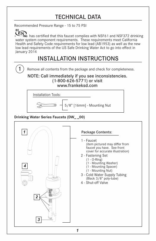
TECHNICAL DATA
has certified that this faucet complies with NSF61 and NSF372 drinking water system component requirements. These requirements meet California Health and Safety Code requirements for low lead (AB1953) as well as the new low lead requirements of the US Safe Drinking Water Act to go into effect in January 2014
INSTALLATION INSTRUCTIONSRemove all contents from the package and check for completeness.1NOTE: Call immediately if you see inconsistencies.
(1-800-626-5771) or visitwww.frankeksd.com
Package Contents:
1 - Faucet (item pictured may differ from faucet you have. See front cover for accurate illustration)2 - Fastening Set (1 - O-Ring) (1 - Mounting Washer) (1 - Mounting Spacer) (1 - Mounting Nut)3 - Cold Water Supply Tubing (Black 3/8” poly-tube)4 - Shut-off Valve
Installation Tools:
5/8” [16mm] - Mounting Nut
1
Recommended Pressure Range - 15 to 75 PSI
1
Drinking Water Series Faucets (DW_ _00)
2
3
4

Installation
2
Package Contents:
1 - Faucet (item pictured may differ from faucet you have. See front cover for accurate illustration)2 - Fastening Set (1 - O-Ring) (1 - Mounting Washer) (1 - Mounting Spacer) (1 - Mounting Nut)3 - Cold Water Supply Tubing (black 3/8” poly-tube)4 - Heating Tank Supply Tubing (red ¼”poly-tube – comes pre assembled with faucet)5 - Heating Tank Return Tubing (high-temp silicone tube – comes pre assembled with faucet)6 - Shut-off Valve
Little Butler® Series Hot only Faucets (LB_100)
Package Contents:
1 - Faucet (item pictured may differ from faucet you have. See front cover for accurate illustration)2 - Fastening Set (1 - O-Ring) (1 - Mounting Washer) (1 - Mounting Spacer) (1 - Mounting Nut)3 - Cold Water Supply Tubing (2 -blue 1/4” poly-tubes)4 - Heating Tank Supply Tubing (red ¼”poly-tube - comes pre assembled with faucet)5 - Heating Tank Return Tubing (high-temp silicone tube - comes pre assembled with faucet)6 - 1/4” Tee Fitting7 - Tee Tubing (blue ¼” poly-tube)8 - 1/4” x 3/8” Reducing Union Fitting9 - Cold Water Supply Tubing (black 3/8” poly-tube)10 - Shut-off Valve
Little Butler® Series Hot and Cold Faucets (LB_200)
1
2
4
35
6
1
2
34
5
6
7
8
9
10

Installation
2 Franke recommends the installer familiarize themselves with how this dispensing faucet will be installed and function as part of a point-of-use hot water, a filtration only drinking water, or a combination hot and filtered point-of-use water dispensing arrangement BEFORE the products are installed. Make certain to observe all local plumbing and building codes during installation of this unit.
It is important to identify the dispenser to be installed as this guide applies to multiple configurations. The hot water dispensing faucets are part of the Little Butler® Series. There are 2 different styles of Little Butler® Series dispensers available:
The LB_200 Series dispensers offer hot and filtered water separately. These dispensers must be used in conjunction with both a Franke heating tank unit and a Franke filtration system. They utilize 4 tubes to connect to the system. • 2 blue poly-tubes for the cold water supply into the dispensing faucet, which comes from the filtration system. • 1 red poly-tube to carry the filtered water from the dispensing faucet to the heating tank unit. • 1 opaque high temperature silicone tube to carry the heated water from the heating tank back to the dispensing faucet.
The LB_100 Series dispensers offer hot water only. These dispensers are required to be used in conjunction with a Franke heating tank unit. Use of a Franke filtration system in addition to the heating tank is optional, but strongly recommended in order to prolong the life and improve the performance of the heating tank, as well as providing much higher quality water as compared to un-filtered water entering the tank. These models utilize 3 tubes to connect to the system. • 1 black poly-tube for the cold water supply to the dispensing faucet, which must come from the home water supply or from the filtration system (if utilized). • 1 red poly-tube to carry the filtered water from the dispensing faucet to the heating tank unit. • 1 opaque high temperature silicone tube to carry the heated water from the heating tank back to the faucet.
The filtered water only dispensing faucets are part of the Drinking Water Series, which are designated as DW_ _00 models. These dispensing faucets will only be used in conjunction with a Franke filtration system. There will only be one black poly-tube to connect the faucet to the filtration system.
IMPORTANT: Customer MUST USE genuine Franke components (see below) in tandem with all Franke dispensing faucets. Use of any filtration products, heating tanks, or service parts other than genuine Franke components will VOID THE PRODUCT WARRANTY in its entirety. Use of any Franke dispensing faucet with a Reverse Osmosis Filtration system will also VOID THE PRODUCT WARRANTY.
3
Franke HT-200Heating Tank
Franke FRCNSTR100Filtration System
Franke FRCNSTRFiltration System

Installation
3 It is recommended to take the components and locate their optimum positions before starting the installation. Make sure there is adequate clearance for the dispenser handle(s) to open fully without interference. Make sure all plumbing and electrical connections will reach the intended mounting positions for all the components and there will be no obstructions or sharp bends in plumbing. Make sure the counter top is no thicker than 2-¼”.
WARNING: Before inserting poly-tubing into the push fittings in subsequent steps, ensure the ends of the tubing used are cut square and free of burrs, both inside and outside. Ensure there are no gouges, scratches, or any other form of damage within 1” from the cut end of the tubing. Damage in this area can cause leakage. Do NOT use any thread sealant, plumbers putty, glue, or other adhesive chemicals on the tubing or push fittings. This can damage the o-rings inside the push fittings and cause leakage. Any foreign substances used on the push fitting connections will VOID THE PRODUCT WARRANTY. Do not use tools or modify any of the push fit connections as this could damage the connection, resulting in leaks and will VOID THE PRODUCT WARRANTY.
3
3/8”Black Tubing
ToFiltration System
Shut-off Valve
To Kitchen Faucet
Cold Water Supply
Kitchen FaucetCold Water Inlet
Push Fit Connections
Collar
NOTE: When installing poly-tubing into push fit connections, the tubing should be firmly pressed into the fitting until it stops to ensure a proper seal. If you should need to remove the tubing from the push fitting, use your thumb and forefinger to press and hold in on the collar while gently pulling the tube out.
4 First, the cold water supply to the dispensing faucet needs to be created. Install the Shut-off valve provided by placing it between the cold water supply connection to the kitchen faucet and the kitchen faucet cold water inlet connection. Cut the black 3/8” poly-tubing to the required length to provide water from the shut-off valve to the filtration system. (You should have some poly-tubing left over. In the unlikely event you should need more black 3/8” poly-tubing to complete the installation, please contact our Customer Service Department at 1-800-626-5771.) Connect the black 3/8” poly-tubing to the shut-off valve by pressing the tubing firmly into the push fitting on the shut-off valve until it stops. Connect the other end of the 3/8” poly-tubing to the filtration system as outlined in the instructions provided with the filtration system. Take the remaining black 3/8”poly-tubing and set it aside for later use.
NOTE: For the Drinking Water Series Faucets (DW_ _ 00), there is a service label attached to one end of the black 3/8” poly-tubing. Be sure the tubing set aside for later use has this service label attached as it will be connected to the faucet later. It is important this label remains connected to the faucet should you ever need to service the faucet. For the Little Butler series faucets (LB_100 and LB_200), the service label will be attached to the hot water supply line from the factory.
4

5 Next, Connect the cold water supply tubing to the faucet. This will differ depending on which dispensing faucet you have.
• For Drinking Water Series Faucets (DW_ _00) and Little Butler® Series Hot only Faucets (LB_100) , insert the remainder of the black 3/8” cold water supply tubing left over from Step 4 into the 3/8” push fitting at the base of the faucet as illustrated.
• For the Little Butler® Series Hot and Cold Faucets (LB_200), insert the 2 blue ¼” cold water supply tubes into the ¼” push fittings at the base of the faucet as illustrated.
Installation
3/8”Black
Tubing
3/8”Push
Fitting
1/4”Blue
Tubing
1/4”Push
Fittings
O-Ring
Ensure proper hole is in place for the faucet. This faucet is designed for a 1-3/8” (35mm) mounting hole. Before inserting the faucet in the hole in the sink or counter top, make sure the O-ring is positioned in its seat and all hoses are secure. Place the faucet in the hole, orienting the spout towards the sink bowl.
6
5

7 NOTE: Depending on counter top thickness, it may be easier to access the mounting nut by disconnecting the cold water supply hose(s).
Install fastening set as shown: mounting washer, mounting spacer (if necessary), and mounting nut. Tighten the mounting nut with wrench from the underside of the sink. The mounting spacer is only needed for installations where the faucet is mounted directly to a stainless steel sink, or where the counter top is less than ½” thick.
Installation
Mounting Washer
Mounting Nut
8 Complete the assembly of the cold water supply tubing by inserting the 2 - 1/4” blue poly-tubes already connected to the faucet into 1/4” tee push fitting. Be careful not to kink the tubes. Take the tee tubing, the short piece of blue ¼” poly-tubing, and connect it to the bottom part of the ¼” tee and to the 1/4” x 3/8” reducing union fitting. Lastly, take the part of the black 3/8” poly-tube left over from Step 4 and connect it to the 1/4” x 3/8” reducing union fitting.
NOTE: Step 8 is only required on Little Butler® Series dispensers that offer hot and cold water separately (LB_200 Series dispensers). If you have a Little Butler® hot water only (LB_100 Series) dispenser or a Drinking Water only (DW_ _00 Series) dispenser, go to Step 9.
3/8” x1/4”Reducing Union
1/4” tee
Push Fit Connections
collar
Mounting Spacer
FromFaucet
FromFaucet
Blue 1/4”Tee Tubing
9 Take the black 3/8” poly-tubing from the faucet and connect it to the outlet of the filtration system as outlined in the filtration system instructions. If you decide not to utilize a filtration system with your LB_100 Series faucet, you must provide a connection for the black 3/8” poly-tube to the home’s cold water supply. This will complete the installation for the Drinking Water only (DW_ _00 Series) dispensing faucets. For Little Butler® Series dispensers (LB_100 and LB_200) continue to Step 10.
5 6

10 Connect the red ¼” Heating Tank Supply Hose to the heating tank inlet and the high temp silicone Heating Tank Return Hose to the heating tank outlet per the instructions provided with the heating tank.
Installation
7
TubingConnections to
Heating Tank
Red Heating Tank Supply Tubing
Silicone Heating
Tank Return Tubing
TubingConnections to
Heating Tank
Red Heating Tank Supply Tubing
Silicone Heating
Tank Return Tubing
3/8” Black Poly-tubing
3/8” Black Poly-tubing
1 Push the handle(s) back to turn on the water supply. The cold valve will lock in the ‘on’ position and the hot valve (on the left side if equipped) has a safety feature that requires constant force to keep the valve open to protect from unintentional contact with hot water.
Note: The spout has a 360° swivelcapability
Usage
HOTCOLD
ON OFF
LB_200
LB_100
7 8
Usage
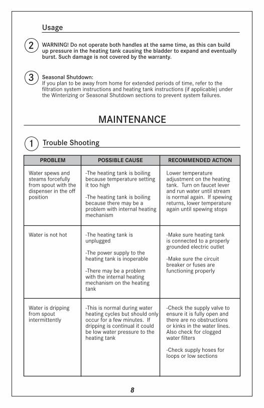
2 WARNING! Do not operate both handles at the same time, as this can build up pressure in the heating tank causing the bladder to expand and eventually burst. Such damage is not covered by the warranty.
3 Seasonal Shutdown:If you plan to be away from home for extended periods of time, refer to the filtration system instructions and heating tank instructions (if applicable) under the Winterizing or Seasonal Shutdown sections to prevent system failures.
MAINTENANCE
Trouble Shooting
PROBLEM
1POSSIBLE CAUSE RECOMMENDED ACTION
Water spews and steams forcefully from spout with the dispenser in the off position
-The heating tank is boiling because temperature setting it too high
-The heating tank is boiling because there may be a problem with internal heating mechanism
Lower temperature adjustment on the heating tank. Turn on faucet lever and run water until stream is normal again. If spewing returns, lower temperature again until spewing stops
Water is not hot -The heating tank isunplugged
-The power supply to theheating tank is inoperable
-There may be a problemwith the internal heating mechanism on the heating tank
-Make sure heating tank is connected to a properly grounded electric outlet
-Make sure the circuit breaker or fuses arefunctioning properly
Water is dripping from spoutintermittently
-This is normal during water heating cycles but should only occur for a few minutes. If dripping is continual it could be low water pressure to the heating tank
-Check the supply valve to ensure it is fully open and there are no obstructions or kinks in the water lines. Also check for clogged water filters
-Check supply hoses for loops or low sections

9
Replacement Parts2
1
3
4
7
5
9 9
8
12
* Must Identify Color/ Finish when ordering replacement parts.
2
6
10
11
2
3
4
7
5
8
12
6
1
3
4
7
5
8
12
6
DW_ _00 Series(Faucet pictured may differ from
faucet you have. See frontcover for accurate illustration.)
LB_100 Series(Faucet pictured may differ from
faucet you have. See frontcover for accurate illustration.)
LB_200 Series(Faucet pictured may differ from
faucet you have. See frontcover for accurate illustration.)
#4 Replacement Levers Per Series5000Series
6000Series
7000Series
8000Series
9000Series
+ Hot or Cold indicators included with specified lever.For replacement indicators only, order 5-015R for red and 5-015B for blue.
+ + +
Model #
LB5100 SeriesLB5200 SeriesDW5000 SeriesLB6100 SeriesLB6200 SeriesDW6100 SeriesLB7100 SeriesLB7200 SeriesDW7000 SeriesLB8100 SeriesLB8200 SeriesDW8000 SeriesLB9100 SeriesLB9200 SeriesDW9000 Series
Replacement Part # for Identified Part#1
Cold Cartridge
Assy.
#2 Hot
Cartridge Assy.
#3 CoverNut
#4 Lever Assembly(see chart below
for all series)
HotCold
#5 Mounting Washer
#6 Mounting
Spacer
#7Mounting
Nut
#8 Cold Water Supply Tubing
(3/8” OD)
#9 Cold Water Supply Tubing
(1/4” OD)
#10 1/4” Tee Fitting
#11 1/4” x 3/8” Reducing
Union Fitting
-5-0015-001
-5-0015-001
-5-0015-001
-5-0015-001
-5-0015-001
5-0025-002
-5-0025-002
-5-0025-002
-5-0025-002
-5-0025-002
-
5-003*5-003*5-003*5-003*5-003*5-003*5-003*5-003*5-003*5-003*5-003*5-003*5-003*5-003*5-003*
-5-004*5-004*
-5-010*5-010*
-5-011*5-011*
-5-012*5-012*
-5-013*5-013*
5-004*5-004*
-5-010H*5-010H*
-5-011H*5-011H*
-5-012*5-012*
-5-013H*5-013H*
-
5-0075-0075-0075-0075-0075-0075-0075-0075-0075-0075-0075-0075-0075-0075-007
5-0145-0145-0145-0145-0145-0145-0145-0145-0145-0145-0145-0145-0145-0145-014
5-0085-0085-0085-0085-0085-0085-0085-0085-0085-0085-0085-0085-0085-0085-008
103051030510305103051030510305103051030510305103051030510305103051030510305
-10308
--
10308--
10308--
10308--
10308-
-10321
--
10321--
10321--
10321--
10321-
-10322
--
10322--
10322--
10322--
10322-
#12 Shut-off
Valve
103061030610306103061030610306103061030610306103061030610306103061030610306

LIMITED LIFETIME WARRANTYCongratulations on the purchase of this Franke product! Franke is one of the world’s largest manufacturers of kitchen systems. Our products are manufactured using the highest degree of technology quality and design. As a result we are proud to offer the following warranty.
Franke Inc. Kitchen Systems Division, warrants the quality of its water dispensing systems to be free from manufacturing defects for a period of five years from the date of purchase. This warranty applies only to the original owner, providing the product has been installed in accordance with theseinstallation instructions, used as recommended and in a normal residential application. In the event of a warranty claim, the owner will be required to provide proof of purchase – SAVE ORIGINAL SALES RECEIPT! This warranty covers all components necessary to restore the product to good workingcondition. Franke reserves the right to inspect the installation prior to the replacement of the product or component part.
Marine and Outdoor Installation: Franke Consumer Products, Inc. faucets are NOT warranted for Marine and Outdoor installations.
This warranty does not cover misuse or abuse, accidental damage, scuffs or scratches, abnormal usage, negligence or damage caused by impropermaintenance or cleaning. Normal wear of parts is excluded from warranty.Damage caused by impurities or acts beyond Franke’s control are not covered.Any product or part which has been repaired or altered in any manner outside of Franke’s factory, unless previously authorized in writing by Franke, will void warranty. Any replacement excludes transportation and any laborreinstallation costs. This warranty does not allow recovery of incidental or consequential damages such as loss of use, delay, property damage or other consequential damage, and Franke accepts no liability for such damages.
The Franke warranty is limited to the above condition and to the warranty period specified herein and is exclusive. Franke DISCLAIMS all other warranties, expressed or implied, including the IMPLIED WARRANTIES OFMERCHANTABILITY AND/OR FITNESS FOR A PARTICULAR PURPOSE. This warranty gives you specific legal rights which may vary from state to state.
Further InformationFor any further information about our products, about the installation of them, or about the guarantee, please contact our Customer Service Department:
Franke Consumer Products Inc.,Kitchen Systems Division800 Aviation Parkway Smyrna, TN 37167Phone: 1-800-626-5771Fax: 1-888-685-0007www.frankeksd.com

Franke Consumer Products Inc.,Kitchen Systems Division
800 Aviation Parkway Smyrna, TN 37167
Phone: 1-800-626-5771Fax: 1-888-685-0007www.frankeksd.com