Embed Size (px)
Citation preview

HP A-F1000-A-EI/A-F1000-S-EI VPN Firewall Installation Guide
Part number: 5998-1415
Document version: 6PW100-20110909
Legal and notice information
© Copyright 2011 Hewlett-Packard Development Company, L.P.
No part of this documentation may be reproduced or transmitted in any form or by any means without prior written consent of Hewlett-Packard Development Company, L.P.
The information contained herein is subject to change without notice.
HEWLETT-PACKARD COMPANY MAKES NO WARRANTY OF ANY KIND WITH REGARD TO THIS MATERIAL, INCLUDING, BUT NOT LIMITED TO, THE IMPLIED WARRANTIES OF MERCHANTABILITY AND FITNESS FOR A PARTICULAR PURPOSE. Hewlett-Packard shall not be liable for errors contained herein or for incidental or consequential damages in connection with the furnishing, performance, or use of this material.
The only warranties for HP products and services are set forth in the express warranty statements accompanying such products and services. Nothing herein should be construed as constituting an additional warranty. HP shall not be liable for technical or editorial errors or omissions contained herein.
i
Contents
Product overview·························································································································································· 1 Front panel view································································································································································1 Rear panel view ································································································································································1
Preparing for installation ············································································································································· 3 Safety recommendations ··················································································································································3
Safety symbols ··························································································································································3 General safety recommendations ···························································································································3 Safety with electricity ···············································································································································3 Safety with laser ·······················································································································································4
Examining the installation site ·········································································································································4 Temperature and humidity·······································································································································4 Altitude ······································································································································································5 Cleanness ··································································································································································5 Cooling system ·························································································································································5 ESD prevention ·························································································································································6 EMI·············································································································································································7 Lightning protection··················································································································································7 Rack-mounting···························································································································································7
Installation tools·································································································································································7 Accessories supplied by the firewall ·······························································································································8 Checklist before installation ·············································································································································8
Installing the firewall ··················································································································································10 Installation flow ······························································································································································ 10 Installing the firewall in a 19-inch rack························································································································ 10 Grounding the firewall ·················································································································································· 12 Installing an interface module······································································································································· 13 Connecting Ethernet cables··········································································································································· 14
Connecting a copper Ethernet cable··················································································································· 14 Connecting an optical fiber ································································································································· 14
Installing the power supply and connecting the power cord ···················································································· 16 Installing a power supply ····································································································································· 16 Connecting an AC power cord ··························································································································· 16 Connecting the DC power cable ························································································································· 17
Logging in to the firewall and configuring basic settings ·······················································································18 Logging in to the firewall through the console port···································································································· 18
Connecting the firewall to a configuration terminal through a console cable················································ 18 Setting terminal parameters·································································································································· 19
Powering on the firewall ··············································································································································· 21 Checking before power-on··································································································································· 21 Checking after power-on ······································································································································ 21
Logging in to the firewall through Telnet ····················································································································· 22 Logging to the firewall through a web browser·········································································································· 22 Performing basic settings for the firewall····················································································································· 23
Launching the basic configuration wizard·········································································································· 23 Configuring the system name and user password····························································································· 24 Configuring service management························································································································ 25 Configuring the IP address for an interface········································································································ 26
ii
Configuring NAT··················································································································································· 27 Completing the configuration wizard ················································································································· 29
Hardware management and maintenance ··············································································································30 Displaying detailed information about the firewall ···································································································· 30 Displaying software and hardware version information of the firewall ··································································· 31 Displaying the electrical label information of the firewall ························································································· 31 Displaying the CPU usage of the firewall···················································································································· 32 Displaying the memory usage of the firewall·············································································································· 32 Displaying the operational status of the fans ·············································································································· 32 Displaying the operational status of a power supply································································································· 32 Displaying the temperature information of the firewall ······························································································ 33 Displaying operational statistics of the firewall ·········································································································· 33 Saving the running configuration of the firewall ········································································································ 34 Rebooting the firewall···················································································································································· 34
Troubleshooting··························································································································································36 Power supply system failure ·········································································································································· 36 Fan failure ······································································································································································· 36 Configuration terminal problems·································································································································· 37
No terminal display ·············································································································································· 37 Garbled terminal display······································································································································ 37
Password loss ································································································································································· 37 User password loss ··············································································································································· 37 Super password loss ············································································································································· 38
Cooling system failure ··················································································································································· 39 Interface module failure················································································································································· 39
Appendix A Technical specifications ······················································································································40 Dimensions and weight ················································································································································· 40 Storages ·········································································································································································· 40 Power consumption range············································································································································· 40
Power input ···························································································································································· 41 Console port ··································································································································································· 41 Combo interfaces ··························································································································································· 41
Appendix B LEDs·······················································································································································43 Front panel LEDs····························································································································································· 43
Appendix C Interface module··································································································································45 NSQ1XS2U0·································································································································································· 45
Appendix D AC power cables used in different countries or regions ··································································47 10A AC power cables used in different countries or regions··················································································· 47 16A AC power cables used in different countries or regions··················································································· 50
Support and other resources ·····································································································································53 Contacting HP ································································································································································ 53
Subscription service ·············································································································································· 53 Related information························································································································································ 53
Documents ······························································································································································ 53 Websites································································································································································· 53
Conventions ···································································································································································· 54
Index ···········································································································································································56
1
Product overview
This chapter includes these sections:
• Front panel view
• Rear panel view
NOTE:
The A-F1000-S-EI and A-F1000-A-EI share the same appearance. The following section uses the A-F1000-A-EI as an example.
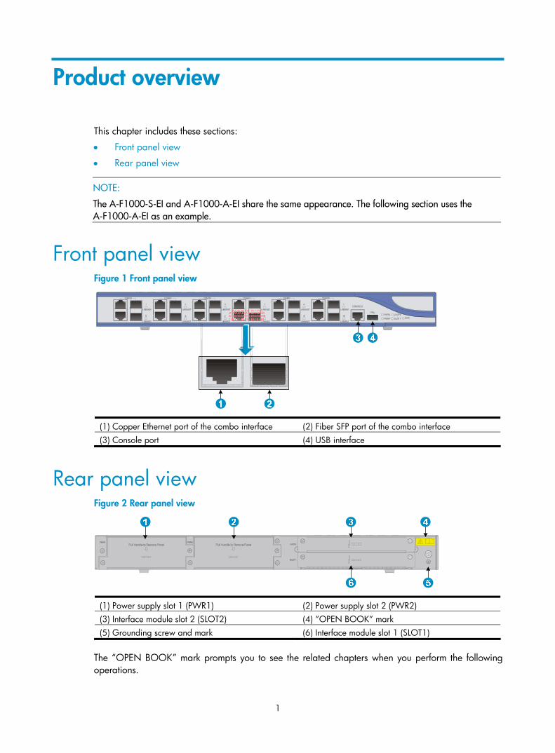
Front panel view Figure 1 Front panel view
(1) Copper Ethernet port of the combo interface (2) Fiber SFP port of the combo interface (3) Console port (4) USB interface
Rear panel view Figure 2 Rear panel view
(1) Power supply slot 1 (PWR1) (2) Power supply slot 2 (PWR2) (3) Interface module slot 2 (SLOT2) (4) ”OPEN BOOK” mark (5) Grounding screw and mark (6) Interface module slot 1 (SLOT1)
The “OPEN BOOK” mark prompts you to see the related chapters when you perform the following operations.

2
Table 1 Description of the “OPEN BOOK” mark
Operation Reference
Grounding the firewall Grounding the firewall
Connecting the firewall to the power source Installing the power supply and connecting the power cord
3
Preparing for installation
This chapter includes these sections:
• Safety recommendations
• Examining the installation site
• Installation tools
• Accessories supplied by the firewall
• Checklist before installation
Safety recommendations To avoid possible bodily injury and equipment damage, read the safety recommendations in this chapter carefully before installing an A-F1000-A-EI/A-F1000-S-EI firewall. The recommendations do not cover every possible hazardous condition.
This section includes these topics:
• Safety symbols
• General safety recommendations
• Safety with electricity
• Safety with laser
Safety symbols When reading this document, note the following symbols:
WARNING means an alert that calls attention to important information that if not understood or followed can result in personal injury.
CAUTION means an alert that calls attention to important information that if not understood or followed can result in data loss, data corruption, or damage to hardware or software.
General safety recommendations • Keep the chassis and installation tools away from walk areas.
• Make sure that the ground is dry and flat and anti-slip measures are in place.
• Unplug all the external cables (including power cables) before moving the chassis.
Safety with electricity • Locate the emergency power-off switch in the room before installation. Shut the power off at once in
case accident occurs.
• Make sure that the firewall has been correctly grounded.
• Connect the interface cables for the firewall correctly.
• Use an uninterruptible power supply (UPS).
4
• If there are two power inputs, disconnect the two power inputs to power off the firewall.
• Do not work alone when the firewall has power.
• Always check that the power has been disconnected.
Safety with laser • Do not stare into the optical port or fiber connector because the laser light emitted from the optical
fiber may hurt your eyes.
• Install a dust plug on the transceiver module to avoid damage to the transceiver module.
Examining the installation site The HP A-F1000-A-EI/A-F1000-S-EI firewall can only be used indoors. To ensure that the firewall works properly and to prolong its service lifetime, the installation site must meet the following requirements:
• Temperature and humidity
• Altitude
• Cleanness
• Cooling system
• ESD prevention
• EMI
• Lightning protection
• Rack-mounting
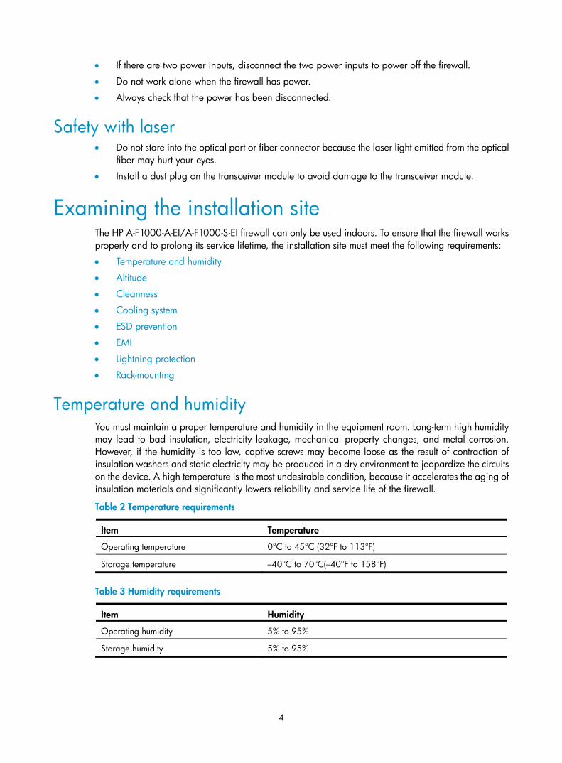
Temperature and humidity You must maintain a proper temperature and humidity in the equipment room. Long-term high humidity may lead to bad insulation, electricity leakage, mechanical property changes, and metal corrosion. However, if the humidity is too low, captive screws may become loose as the result of contraction of insulation washers and static electricity may be produced in a dry environment to jeopardize the circuits on the device. A high temperature is the most undesirable condition, because it accelerates the aging of insulation materials and significantly lowers reliability and service life of the firewall.
Table 2 Temperature requirements
Item Temperature
Operating temperature 0°C to 45°C (32°F to 113°F)
Storage temperature –40°C to 70°C(–40°F to 158°F)
Table 3 Humidity requirements
Item Humidity
Operating humidity 5% to 95%
Storage humidity 5% to 95%
5
Altitude Table 4 Altitude requirements
Item Altitude
Operating altitude –60 m (–196.85 ft) to 3 km (1.86 miles)
Storage altitude –60 m (–196.85 ft) to 4.5km(2.8 miles)
Cleanness Dust buildup on the chassis may result in electrostatic adsorption, which causes poor contact of metal components and contact points, especially when indoor relative humidity is low. In the worst case, electrostatic adsorption can cause communication failure.
Table 5 Dust concentration limit in the equipment room
Substance Concentration limit (particles/cu m)
Dust particles ≤ 3 x 10⁴
(No visible dust on desk in three days)
NOTE:
Dust particle diameter ≥ 5 μm
The equipment room must also meet strict limits on salts, acids, and sulfides to eliminate corrosion and premature aging of components, as shown in Table 6.
Table 6 Harmful gas limits in an equipment room
Gas Max. (mg/m3)
SO2 0.2
H2S 0.006
NH3 0.05
Cl2 0.01
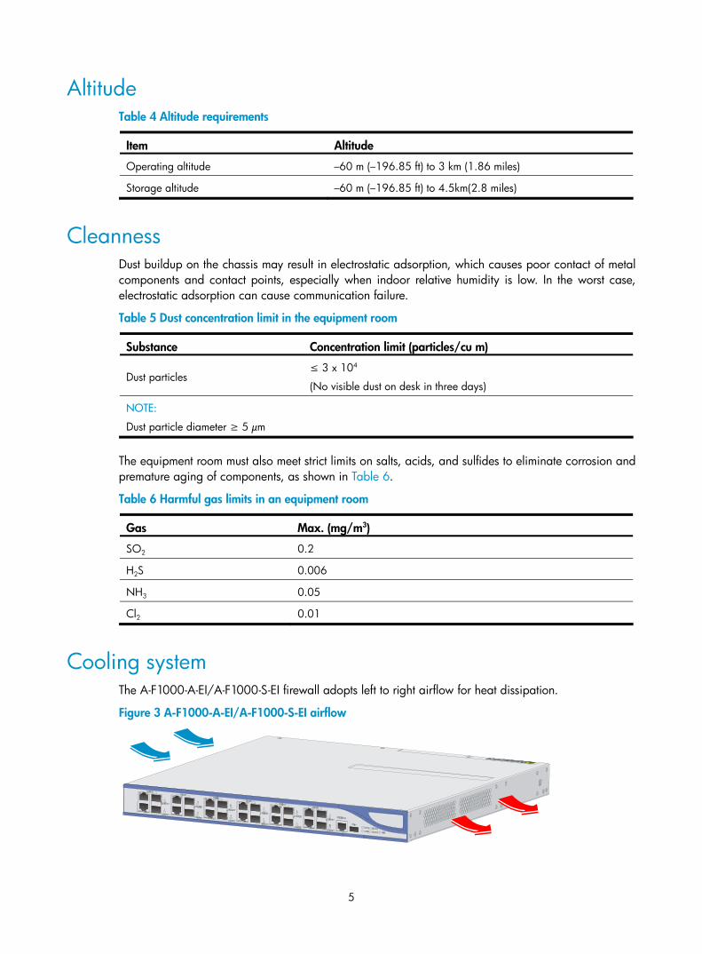
Cooling system The A-F1000-A-EI/A-F1000-S-EI firewall adopts left to right airflow for heat dissipation.
Figure 3 A-F1000-A-EI/A-F1000-S-EI airflow
6
• Make sure there is enough space (greater than 10 cm (3.94 in)) around the air intake and outlet vents on the firewall for good ventilation.
• Make sure the installation site has a good cooling system.
ESD prevention To prevent electrostatic discharge (ESD), note the following guidelines:
• Make sure that the firewall and the floor are well grounded.
• Take dust-proof measures for the equipment room.
• Maintain the humidity and temperature at a proper level.
• Always wear an ESD-preventive wrist strap when touching a circuit board or transceiver module.
• Place the removed interface module on an antistatic workbench, with the face upward, or put it into an antistatic bag.
• Touch only the edges, instead of electronic components when observing or moving a removed interface module.
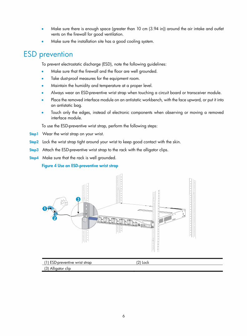
To use the ESD-preventive wrist strap, perform the following steps:
Step1 Wear the wrist strap on your wrist.
Step2 Lock the wrist strap tight around your wrist to keep good contact with the skin.
Step3 Attach the ESD-preventive wrist strap to the rack with the alligator clips.
Step4 Make sure that the rack is well grounded.
Figure 4 Use an ESD-preventive wrist strap
(1) ESD-preventive wrist strap (2) Lock (3) Alligator clip
7
CAUTION:
• Check the resistance of the ESD-preventive wrist strap for safety. The resistance reading should be in therange of 1 to 10 megohm (Mohm) between human body and the ground.
• No ESD-preventive wrist strap is provided with the A-F1000-A-EI/A-F1000-S-EI firewall. Prepare it yourself.
EMI To prevent electromagnetic interference (EMI) when you use the firewall, note the following guidelines:
• Take measures against interference from the power grid.
• Do not use the firewall together with the grounding equipment or light-prevention equipment of power equipment, and keep the firewall far away from them.
• Keep the firewall far away from high-power radio launchers, radars, and equipment with high frequency or high current.
NOTE:
Use electromagnetic shielding when necessary.
Lightning protection To protect the firewall from lightning better, do as follows:
• Make sure the grounding cable of the chassis is well grounded.
• Make sure the grounding terminal of the AC power receptacle is well grounded.
• Install a lightning arrester at the input end of the power supply to enhance the lightning protection capability of the power supply.
Rack-mounting Before mounting the firewall in a standard 19-inch rack, adhere to the following requirements:
• The rack is sturdy enough to support the firewall and installation accessories.
• Make sure that the size of the rack is appropriate for the firewall, and that there is enough clearance around the left and right sides of the firewall for heat dissipation.
• For heat dissipation and device maintenance, make sure the front and rear of the rack should be at least 0.8 m (2.62 ft) away from walls or other devices, and that the headroom in the equipment room should be no less than 3 m (9.84 ft).
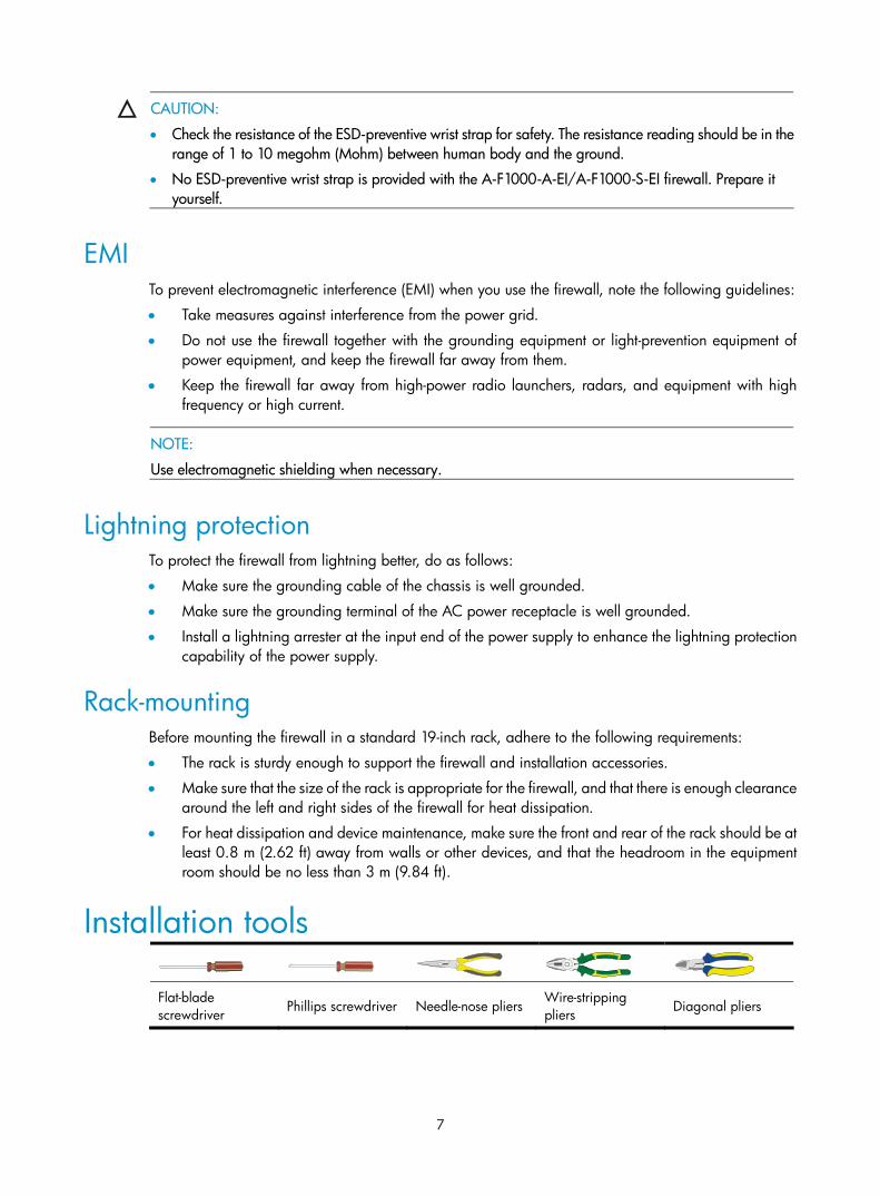
Installation tools
Flat-blade screwdriver Phillips screwdriver Needle-nose pliers
Wire-stripping pliers Diagonal pliers
8
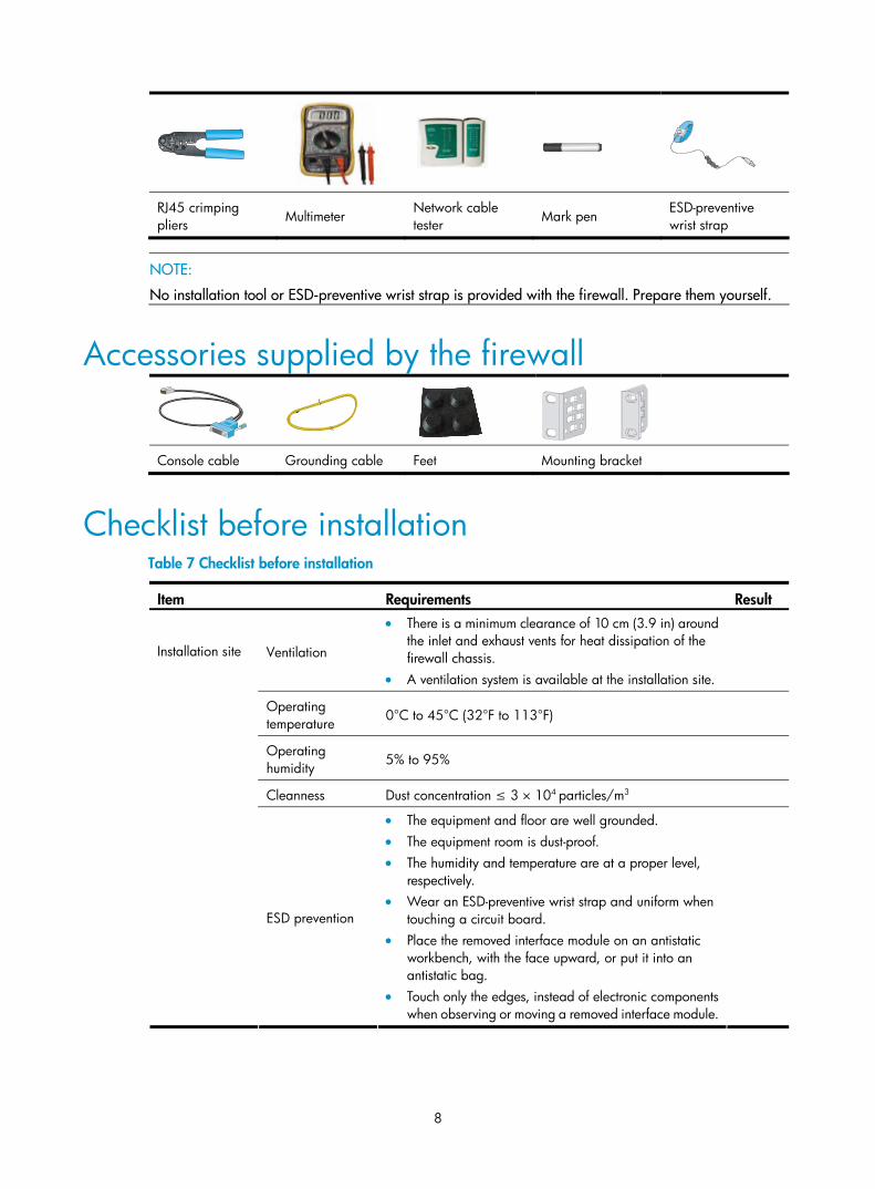
RJ45 crimping pliers Multimeter
Network cable tester Mark pen
ESD-preventive wrist strap
NOTE:
No installation tool or ESD-preventive wrist strap is provided with the firewall. Prepare them yourself.
Accessories supplied by the firewall
Console cable Grounding cable Feet Mounting bracket
Checklist before installation Table 7 Checklist before installation
Item Requirements Result
Ventilation
• There is a minimum clearance of 10 cm (3.9 in) around the inlet and exhaust vents for heat dissipation of the firewall chassis.
• A ventilation system is available at the installation site.
Operating temperature 0°C to 45°C (32°F to 113°F)
Operating humidity 5% to 95%
Cleanness Dust concentration ≤ 3 × 10⁴ particles/m3
Installation site
ESD prevention
• The equipment and floor are well grounded. • The equipment room is dust-proof. • The humidity and temperature are at a proper level,
respectively. • Wear an ESD-preventive wrist strap and uniform when
touching a circuit board. • Place the removed interface module on an antistatic
workbench, with the face upward, or put it into an antistatic bag.
• Touch only the edges, instead of electronic components when observing or moving a removed interface module.
9
Item Requirements Result
EMI prevention
• Take effective measures to protect the power system from the power grid system.
• Separate the protection ground of the firewall from the grounding device or lightning protection grounding device as far as possible.
• Keep the firewall far away from radio stations, radar and high-frequency devices working in high current.
• Use electromagnetic shielding when necessary.
Lightning protection
• The grounding cable of the chassis is well grounded. • The grounding terminal of the AC power receptacle is
well grounded.
Electricity safety • Equip an uninterruptible power supply (UPS). • In case of emergency during operation, switch off the
external power switch.
Rack-mounting requirements
• The rack is sturdy enough to support the weight of the firewall and installation accessories.
• The size of the cabinet is appropriate for the firewall. • The front and rear of the cabinet are at least 0.8 m
(31.50 in) away from walls or other devices.
Safety precautions
• The firewall is far away from any moist area and heat source. • The emergency power switch in the equipment room is located.
Tools • Installation accessories supplied with the firewall • User supplied tools
Reference • Documents shipped with the firewall • Online documents
10
Installing the firewall
This chapter includes these sections:
• Installation flow
• Installing the firewall in a 19-inch rack
• Grounding the firewall
• Installing an interface module
• Connecting Ethernet cables
• Installing the power supply and connecting the power cord
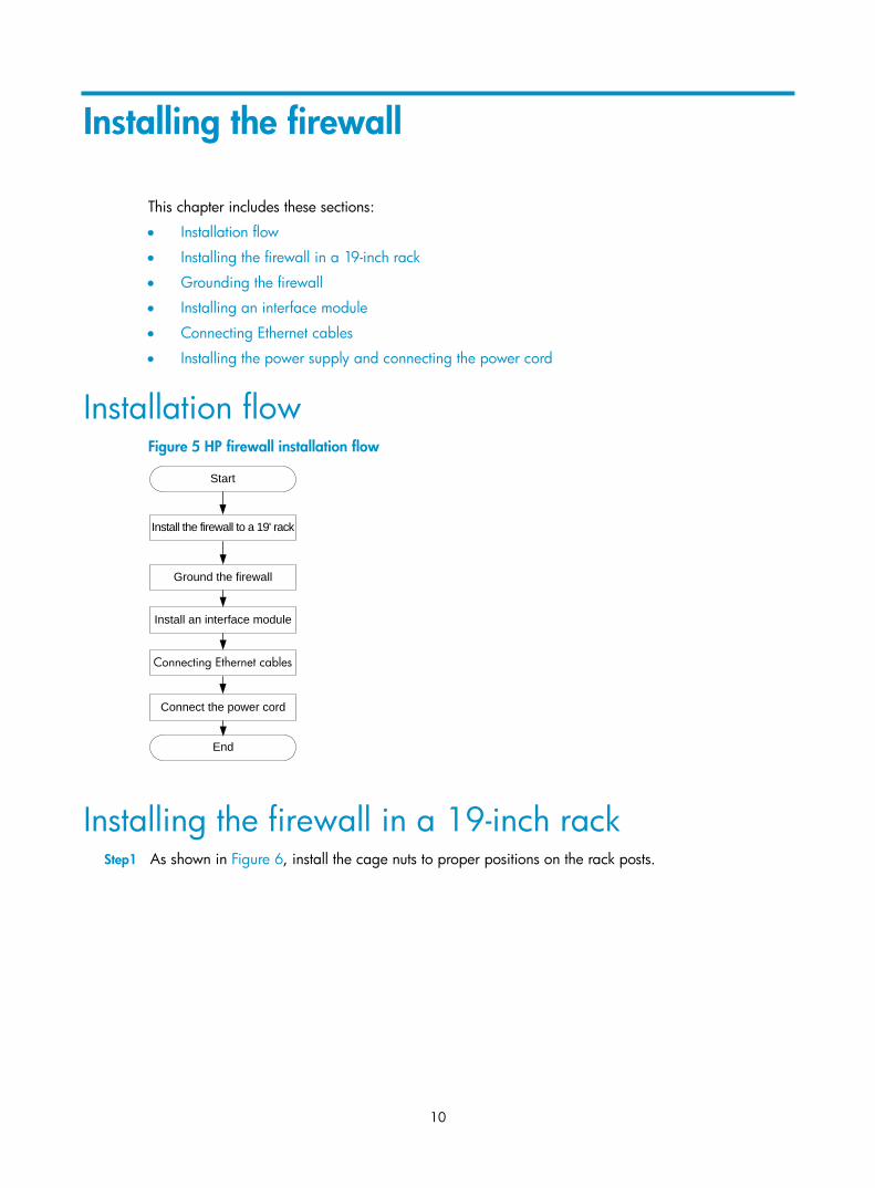
Installation flow Figure 5 HP firewall installation flow
Start
Ground the firewall
Install an interface module
Connect the power cord
Install the firewall to a 19' rack
End
Connecting Ethernet cables
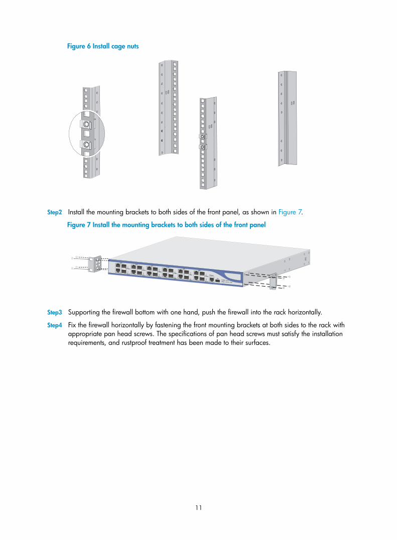
Installing the firewall in a 19-inch rack Step1 As shown in Figure 6, install the cage nuts to proper positions on the rack posts.
11
Figure 6 Install cage nuts
Step2 Install the mounting brackets to both sides of the front panel, as shown in Figure 7.
Figure 7 Install the mounting brackets to both sides of the front panel
Step3 Supporting the firewall bottom with one hand, push the firewall into the rack horizontally.
Step4 Fix the firewall horizontally by fastening the front mounting brackets at both sides to the rack with appropriate pan head screws. The specifications of pan head screws must satisfy the installation requirements, and rustproof treatment has been made to their surfaces.
12
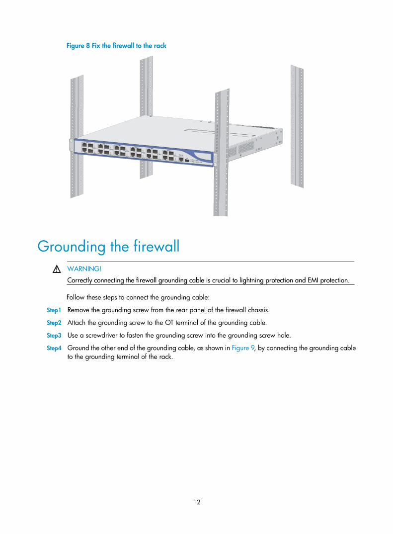
Figure 8 Fix the firewall to the rack
Grounding the firewall
WARNING!
Correctly connecting the firewall grounding cable is crucial to lightning protection and EMI protection.
Follow these steps to connect the grounding cable:
Step1 Remove the grounding screw from the rear panel of the firewall chassis.
Step2 Attach the grounding screw to the OT terminal of the grounding cable.
Step3 Use a screwdriver to fasten the grounding screw into the grounding screw hole.
Step4 Ground the other end of the grounding cable, as shown in Figure 9, by connecting the grounding cable to the grounding terminal of the rack.
13
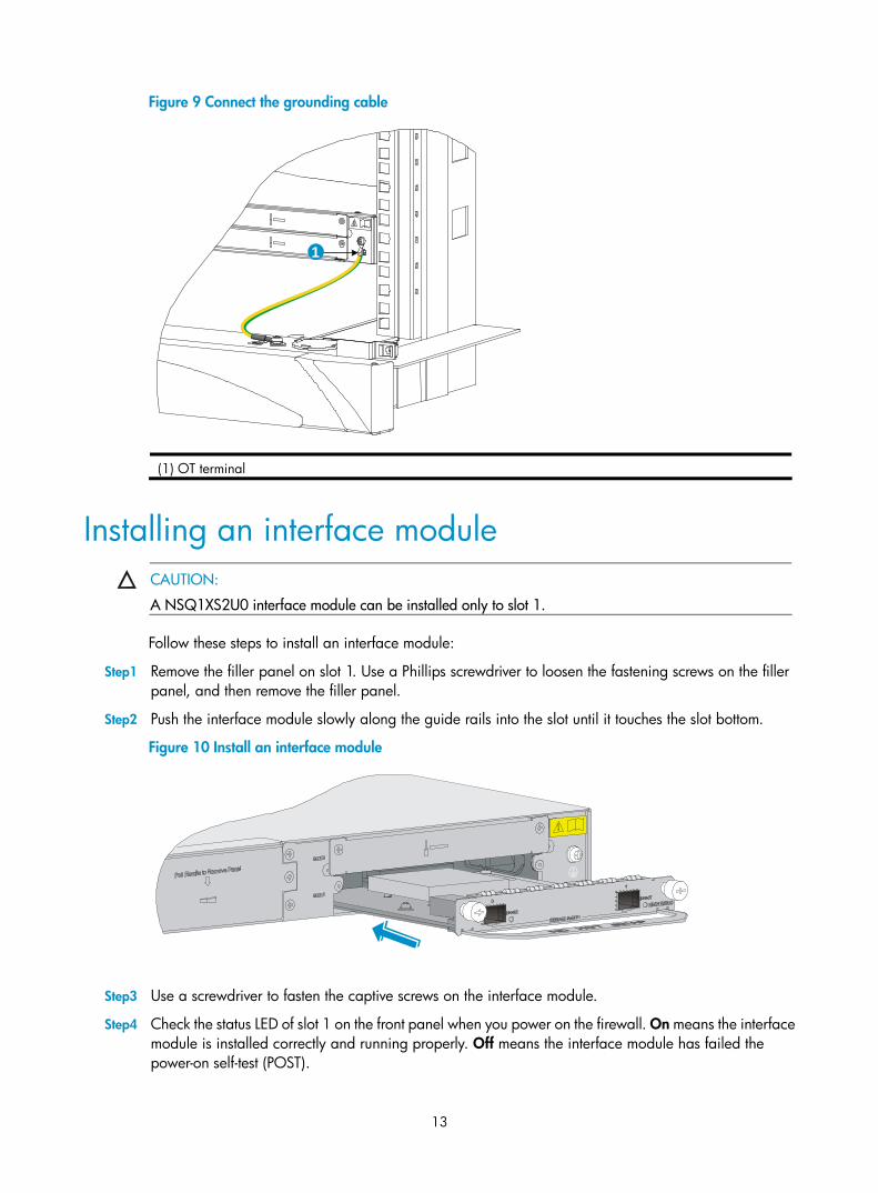
Figure 9 Connect the grounding cable
1
(1) OT terminal
Installing an interface module
CAUTION:
A NSQ1XS2U0 interface module can be installed only to slot 1.
Follow these steps to install an interface module:
Step1 Remove the filler panel on slot 1. Use a Phillips screwdriver to loosen the fastening screws on the filler panel, and then remove the filler panel.
Step2 Push the interface module slowly along the guide rails into the slot until it touches the slot bottom.
Figure 10 Install an interface module
Step3 Use a screwdriver to fasten the captive screws on the interface module.
Step4 Check the status LED of slot 1 on the front panel when you power on the firewall. On means the interface module is installed correctly and running properly. Off means the interface module has failed the power-on self-test (POST).
14
Connecting Ethernet cables
Connecting a copper Ethernet cable Follow these steps to connect a copper Ethernet cable:
Step1 Plug one end of an Ethernet twisted pair cable into the copper Ethernet port (RJ-45 port) to be connected on the firewall.
Step2 Plug the other end of the cable into the RJ-45 port of the peer device.
Step3 After the firewall is powered on, check the status LED of the port. If the LED is solid green, you can be sure that the link is connected. For more information about the LED status, see the chapter “Appendix B LEDs.”
Connecting an optical fiber Before connecting the firewall to the network, you must install a transceiver module to the firewall, and then insert the fiber connector to the transceiver module. The A-F1000-A-EI/A-F1000-S-EI firewall supports LC connectors only.
WARNING!
When connecting an optical fiber, note the following guidelines:
• Never bend or curve a fiber when connecting it. After a fiber is installed well, the bend radius must benot less than 10 cm (3.94 in).
• Keep the fiber end clean.
• Make sure that the fiber connector matches the transceiver module.
• Before connecting a fiber, make sure that the optical power at the receiving end does not exceed the upper threshold of the optical receive power of the transceiver module. Otherwise, the transceiver module may be damaged. For the optical power of a transceiver module, see the chapter “Appendix ATechnical specifications.”
Follow these steps to connect optical fibers:
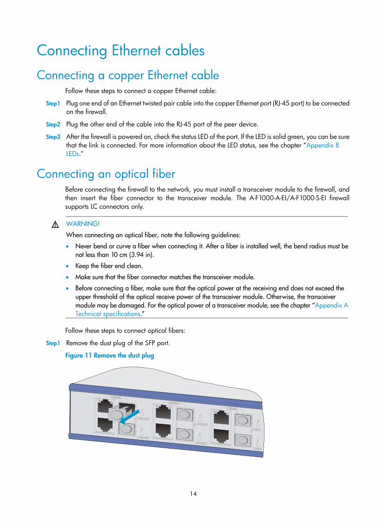
Step1 Remove the dust plug of the SFP port.
Figure 11 Remove the dust plug
15
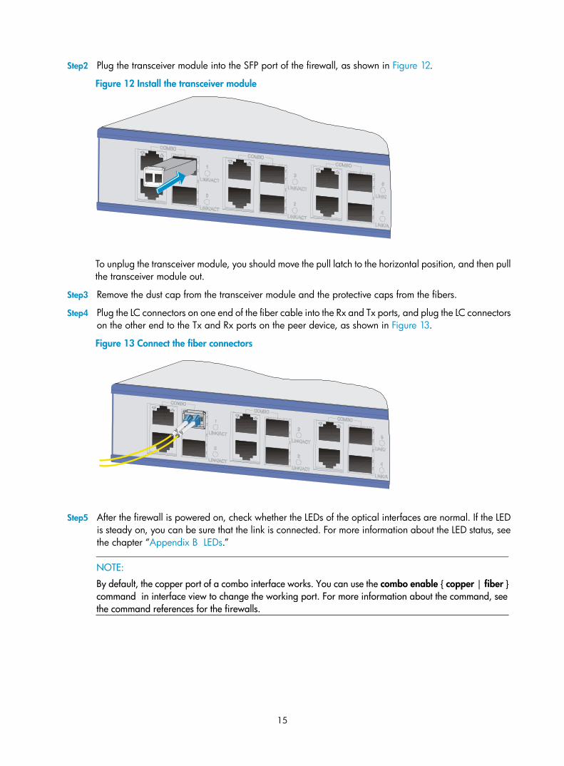
Step2 Plug the transceiver module into the SFP port of the firewall, as shown in Figure 12.
Figure 12 Install the transceiver module
To unplug the transceiver module, you should move the pull latch to the horizontal position, and then pull the transceiver module out.
Step3 Remove the dust cap from the transceiver module and the protective caps from the fibers.
Step4 Plug the LC connectors on one end of the fiber cable into the Rx and Tx ports, and plug the LC connectors on the other end to the Tx and Rx ports on the peer device, as shown in Figure 13.
Figure 13 Connect the fiber connectors
Step5 After the firewall is powered on, check whether the LEDs of the optical interfaces are normal. If the LED is steady on, you can be sure that the link is connected. For more information about the LED status, see the chapter “Appendix B LEDs.”
NOTE:
By default, the copper port of a combo interface works. You can use the combo enable { copper | fiber }command in interface view to change the working port. For more information about the command, see the command references for the firewalls.

16
Installing the power supply and connecting the power cord
NOTE:
• No AC power supply or DC power supply is provided with the firewall.
• You can install two power supplies in your firewall, and they must be the same model.
Installing a power supply The procedures for installing an AC power supply and DC power supply are the same. The following uses an AC power supply as an example.
Step1 Locate the slot to install the power supply. Use a Phillips screwdriver to loosen the fastening screws on the filler panel, and then remove the filler panel.
Step2 Use even pressure to gently push the power supply slowly along the slide rails into the slot.
Figure 14 Insert the power supply into the slot
Step3 Fasten the captive screws on the power supply with a Phillips screwdriver.
Step4 Check the power supply LED when you power on the firewall. If the power supply LED is steady on, the power supply works properly. For more information about LED status, see the chapter “Appendix B LEDs.”
Connecting an AC power cord
To connect an AC power cord, follow these steps:
Step1 Make sure the firewall is well grounded.
Step2 Connect one end of the AC power cord to the AC receptacle on the firewall, and the other end to the AC power source.
Step3 (Optional) Use a cable tie to secure the AC power cord to the power supply handle.
17
Figure 15 Connect an AC power cord
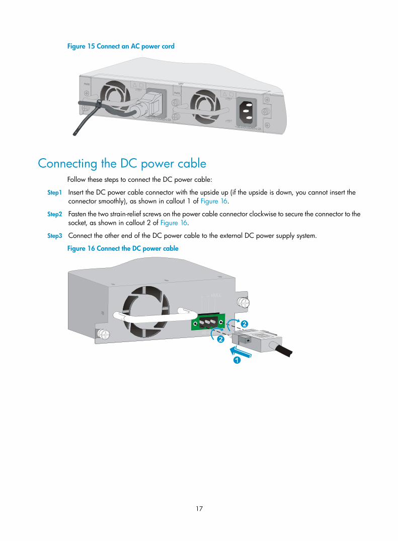
Connecting the DC power cable Follow these steps to connect the DC power cable:
Step1 Insert the DC power cable connector with the upside up (if the upside is down, you cannot insert the connector smoothly), as shown in callout 1 of Figure 16.
Step2 Fasten the two strain-relief screws on the power cable connector clockwise to secure the connector to the socket, as shown in callout 2 of Figure 16.
Step3 Connect the other end of the DC power cable to the external DC power supply system.
Figure 16 Connect the DC power cable
18
Logging in to the firewall and configuring basic settings
This chapter includes these sections:
• Logging in to the firewall through the console port
• Powering on the firewall
• Logging in to the firewall through Telnet
• Logging to the firewall through a web browser
• Performing basic settings for the firewall
This chapter describes only the commonly used methods for logging in to the firewall. For more firewall login methods, such as login through SSH and NMS, see the configuration guides for the firewalls.
Logging in to the firewall through the console port
Connecting the firewall to a configuration terminal through a console cable
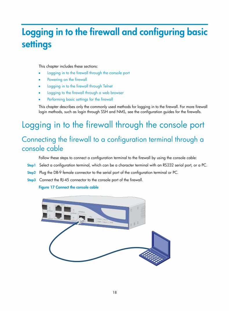
Follow these steps to connect a configuration terminal to the firewall by using the console cable:
Step1 Select a configuration terminal, which can be a character terminal with an RS232 serial port, or a PC.
Step2 Plug the DB-9 female connector to the serial port of the configuration terminal or PC.
Step3 Connect the RJ-45 connector to the console port of the firewall.
Figure 17 Connect the console cable
19
CAUTION:
• When you connect a PC to a powered-on firewall, connect the DB-9 connector of the console cable tothe PC before connecting the RJ-45 connector to the firewall.
• When you disconnect a PC from a powered-on firewall, disconnect the DB-9 connector of the console cable from the PC after disconnecting the RJ-45 connector from the firewall.
Setting terminal parameters Follow these steps to set terminal parameters on a terminal, for example, Windows XP HyperTerminal:
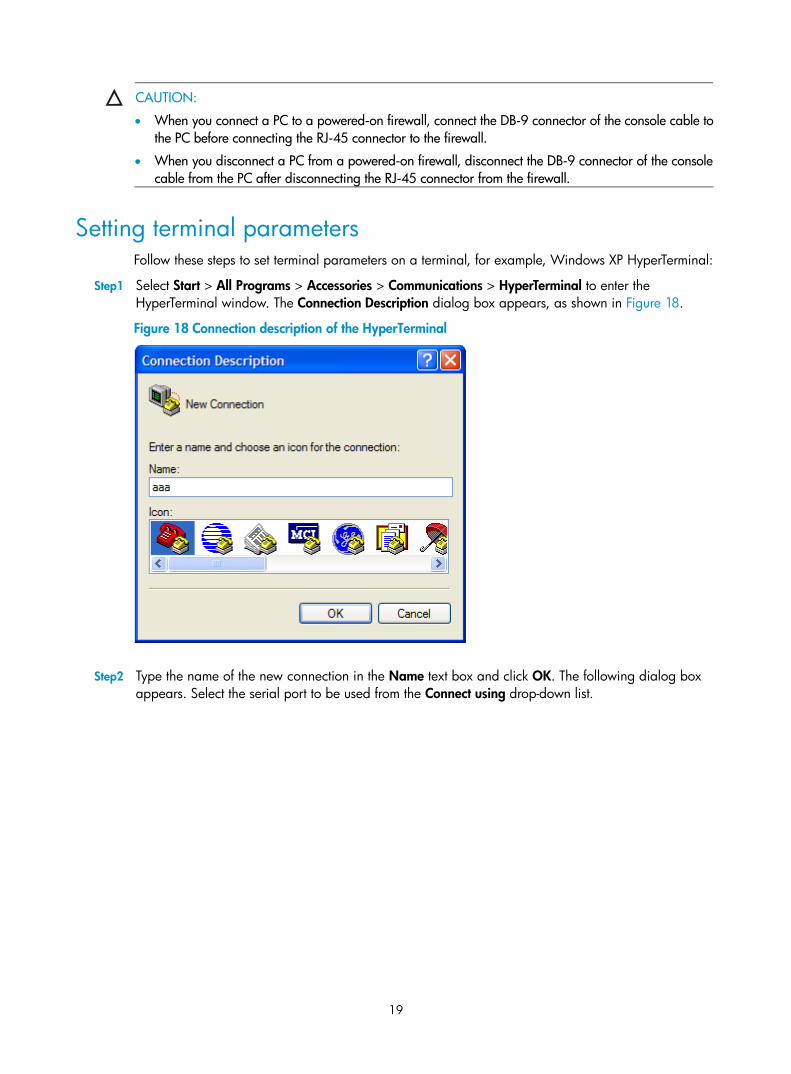
Step1 Select Start > All Programs > Accessories > Communications > HyperTerminal to enter the HyperTerminal window. The Connection Description dialog box appears, as shown in Figure 18.
Figure 18 Connection description of the HyperTerminal
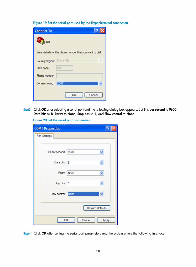
Step2 Type the name of the new connection in the Name text box and click OK. The following dialog box appears. Select the serial port to be used from the Connect using drop-down list.
20
Figure 19 Set the serial port used by the HyperTerminal connection
Step3 Click OK after selecting a serial port and the following dialog box appears. Set Bits per second to 9600, Data bits to 8, Parity to None, Stop bits to 1, and Flow control to None.
Figure 20 Set the serial port parameters
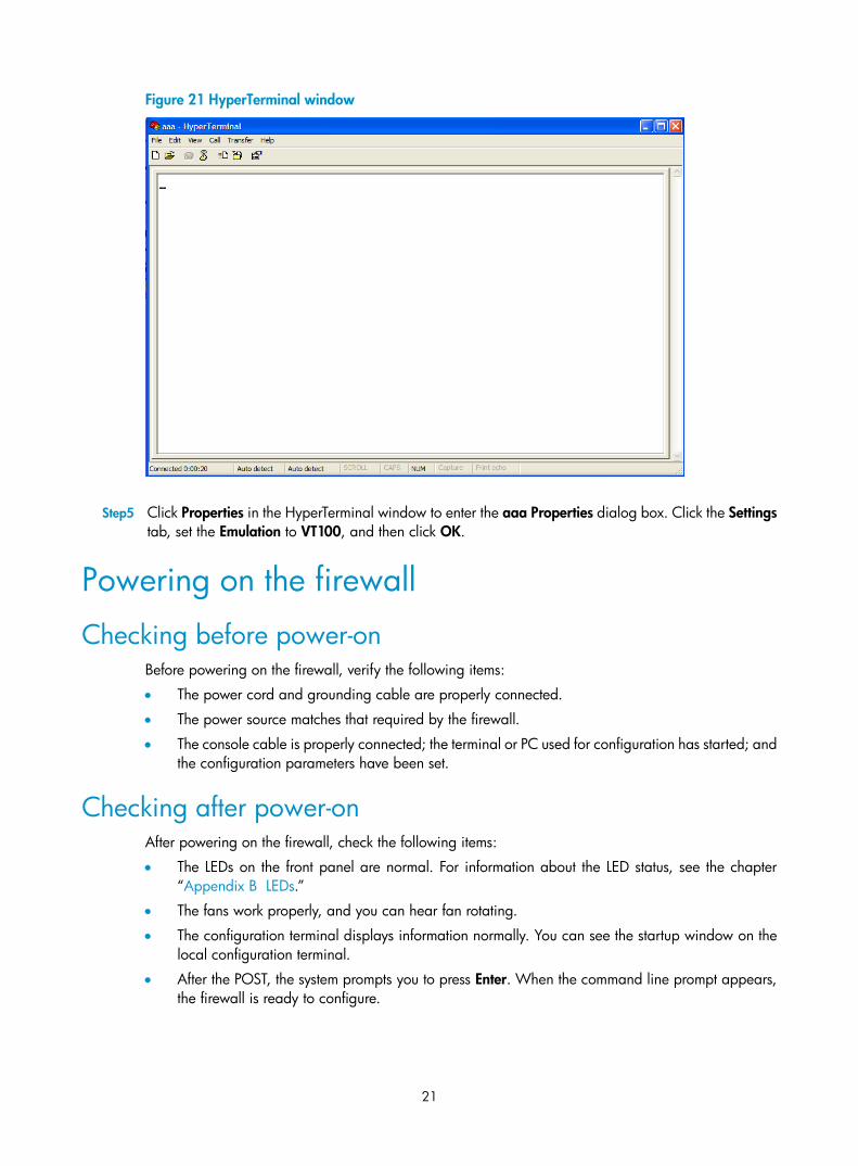
Step4 Click OK after setting the serial port parameters and the system enters the following interface.
21
Figure 21 HyperTerminal window
Step5 Click Properties in the HyperTerminal window to enter the aaa Properties dialog box. Click the Settings tab, set the Emulation to VT100, and then click OK.
Powering on the firewall
Checking before power-on Before powering on the firewall, verify the following items:
• The power cord and grounding cable are properly connected.
• The power source matches that required by the firewall.
• The console cable is properly connected; the terminal or PC used for configuration has started; and the configuration parameters have been set.
Checking after power-on After powering on the firewall, check the following items:
• The LEDs on the front panel are normal. For information about the LED status, see the chapter “Appendix B LEDs.”
• The fans work properly, and you can hear fan rotating.
• The configuration terminal displays information normally. You can see the startup window on the local configuration terminal.
• After the POST, the system prompts you to press Enter. When the command line prompt appears, the firewall is ready to configure.
22
Logging in to the firewall through Telnet
NOTE:
For more information about the Telnet login, see the configuration guides for the firewalls.
You can use the default information to log in to the A-F1000-A-EI/A-F1000-S-EI firewall. The default login information includes:
• Username: admin
• Password: admin
• IP address of port GigabitEthernet 0/0: 192.168.0.1/24
Follow these steps to log in to the firewall through Telnet:
Step1 Log in to the firewall through the console port and then use the telnet server enable command in system view to enable the Telnet function of the firewall.
By default, Telnet is disabled on the firewall.
Step2 Connect the firewall to a PC.
Connect port GigabitEthernet 0/0 of the firewall to a PC by using an Ethernet cable.
Step3 Configure an IP address for the PC, making sure that the PC and the firewall can ping each other.
Set the IP address to any one but 192.168.0.1 within the range of 192.168.0.0/24. For example, set the address to 192.168.0.2.
Step4 Use the Telnet command to log in to the firewall.
Logging to the firewall through a web browser The A-F1000-A-EI/A-F1000-S-EI firewall supports web-based network management, which allows you to manage and maintain the firewall in a more user-friendly way.
Your A-F1000-A-EI/A-F1000-S-EI firewall was delivered with the default web logging information. You can use this default information to log in to the web page of your firewall. The default web logging information includes:
• User name: admin
• Password: admin
• IP address: 192.168.0.1/24
Follow these steps to log in to your firewall through a web browser:
Step1 Connect a cable to the A-F1000-A-EI/A-F1000-S-EI firewall.
Connect the Ethernet interface GigabitEthernet 0/0 of the A-F1000-A-EI/A-F1000-S-EI firewall to a PC by using a network cable.
Step2 Configure an IP address for the PC, ensuring the PC and the A-F1000-A-EI/A-F1000-S-EI firewall can ping each other.
Set the IP address to any one but 192.168.0.1 within the range of 192.168.0.0/24. For example, set the address to 192.168.0.2.
Step3 Launch the web browser and input the login information.
23
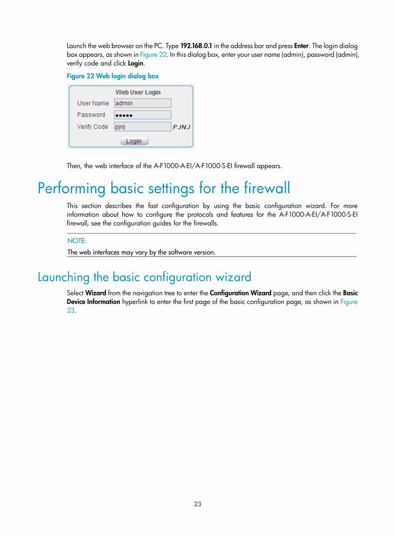
Launch the web browser on the PC. Type 192.168.0.1 in the address bar and press Enter. The login dialog box appears, as shown in Figure 22. In this dialog box, enter your user name (admin), password (admin), verify code and click Login.
Figure 22 Web login dialog box
Then, the web interface of the A-F1000-A-EI/A-F1000-S-EI firewall appears.
Performing basic settings for the firewall This section describes the fast configuration by using the basic configuration wizard. For more information about how to configure the protocols and features for the A-F1000-A-EI/A-F1000-S-EI firewall, see the configuration guides for the firewalls.
NOTE:
The web interfaces may vary by the software version.
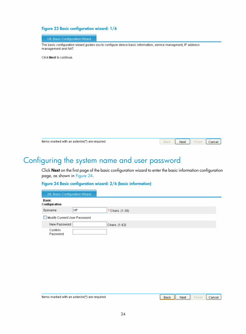
Launching the basic configuration wizard Select Wizard from the navigation tree to enter the Configuration Wizard page, and then click the Basic Device Information hyperlink to enter the first page of the basic configuration page, as shown in Figure 23.
24
Figure 23 Basic configuration wizard: 1/6
Configuring the system name and user password Click Next on the first page of the basic configuration wizard to enter the basic information configuration page, as shown in Figure 24.
Figure 24 Basic configuration wizard: 2/6 (basic information)
25
Table 8 Basic information configuration items
Item Description
Sysname Set the system name. By default, the system name of the firewall is HP.
Modify Current User Password
New Password
Confirm Password
Specify whether to modify the login password of the current user.
To modify the password of the current user, set the new password and the confirm password, and the two passwords must be identical.
By default, the firewall login username and password are both admin.
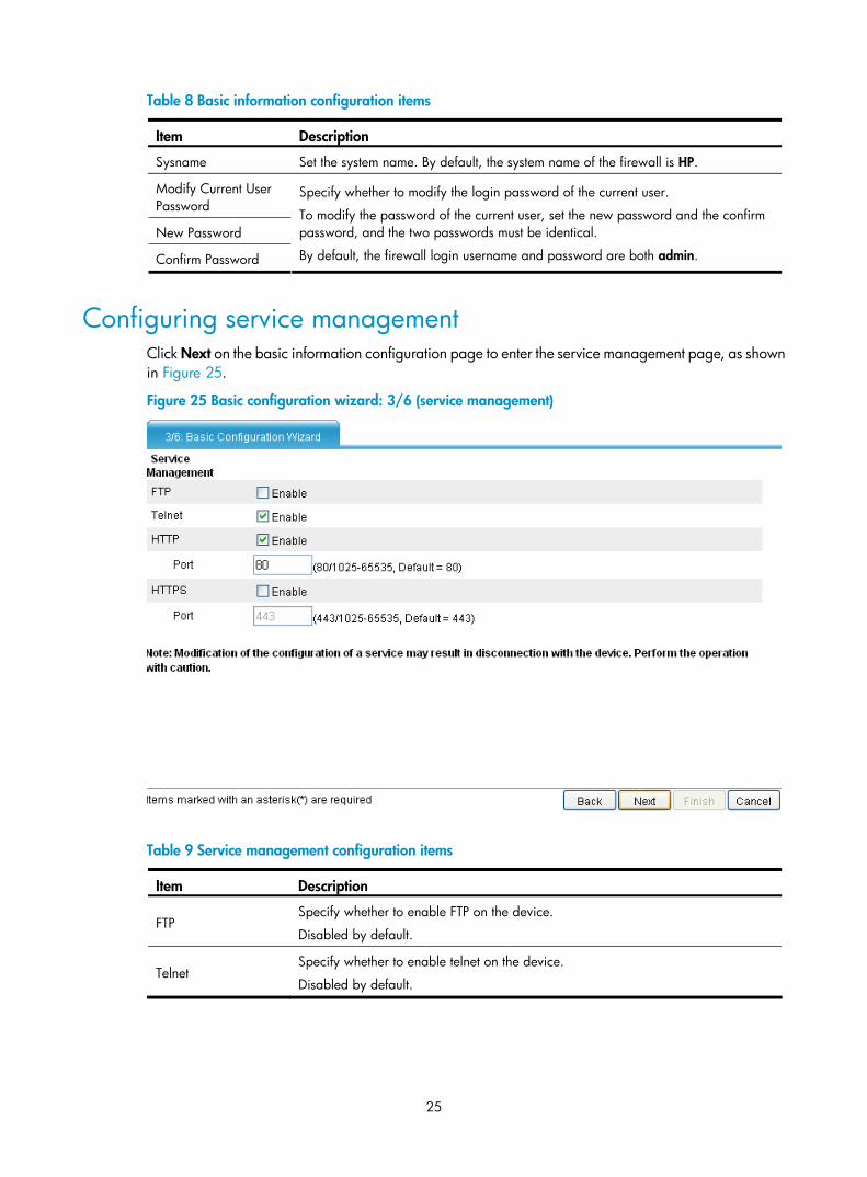
Configuring service management Click Next on the basic information configuration page to enter the service management page, as shown in Figure 25.
Figure 25 Basic configuration wizard: 3/6 (service management)
Table 9 Service management configuration items
Item Description
FTP Specify whether to enable FTP on the device.
Disabled by default.
Telnet Specify whether to enable telnet on the device.
Disabled by default.
26
Item Description
HTTP
Specify whether to enable HTTP on the device, and set the HTTP port number.
Enabled by default.
IMPORTANT: • If the current user has logged in to the web interface through HTTP, disabling HTTP
or modifying the HTTP port number will result in disconnection with the device; therefore, perform the operation with caution.
• When you modify a port number, ensure that the port number is not used by another service.
HTTPS
Specify whether to enable HTTPS on the device, and set the HTTPS port number.
HTTPS is the HTTP protocol that supports the Secure Sockets Layer (SSL) protocol. It can improve device security. For more information about HTTPS.
Disabled by default.
IMPORTANT: • If the current user logged in to the web interface through HTTPS, disabling HTTPS
or modifying the HTTPS port number will result in disconnection with the device; therefore, perform the operation with caution.
• When you modify a port number, ensure that the port number is not used by another service.
• By default, HTTPS uses the PKI domain default. If this PKI domain does not exist, the system will prompt you for it when the configuration wizard is completed; however, this will not affect the execution of other configurations.
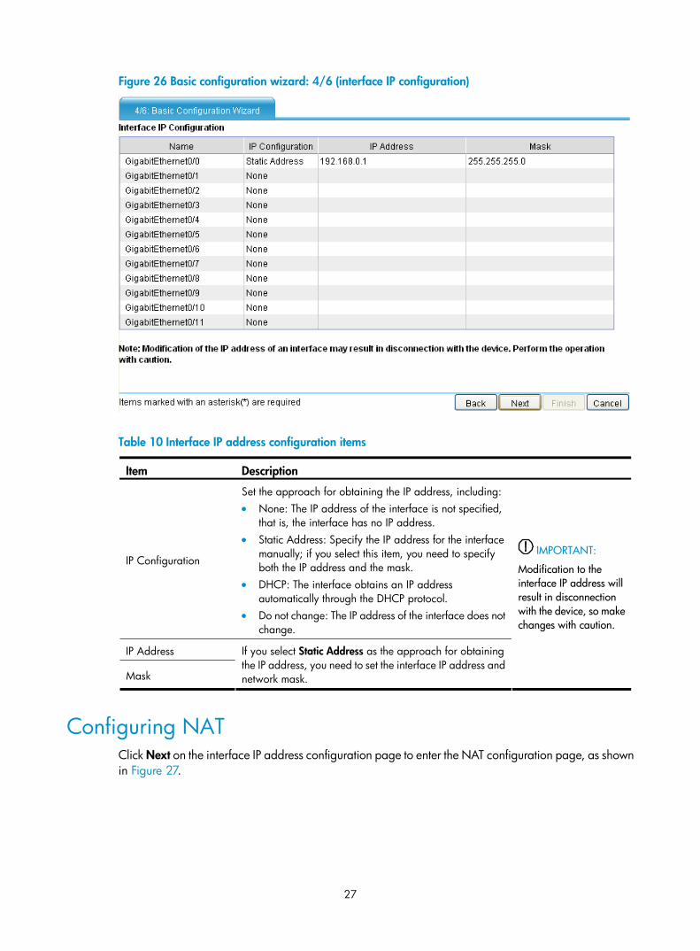
Configuring the IP address for an interface Click Next on the service management configuration page to enter the interface IP address configuration page, as shown in Figure 26. The table lists the IP address configuration information for all Layer 3 Ethernet interfaces and VLAN interfaces. You can click a value in the table and then modify it. Only when the IP configuration is Static Address, can you configure the IP address and mask.
27
Figure 26 Basic configuration wizard: 4/6 (interface IP configuration)
Table 10 Interface IP address configuration items
Item Description
IP Configuration
Set the approach for obtaining the IP address, including: • None: The IP address of the interface is not specified,
that is, the interface has no IP address. • Static Address: Specify the IP address for the interface
manually; if you select this item, you need to specify both the IP address and the mask.
• DHCP: The interface obtains an IP address automatically through the DHCP protocol.
• Do not change: The IP address of the interface does not change.
IP Address
Mask
If you select Static Address as the approach for obtaining the IP address, you need to set the interface IP address and network mask.
IMPORTANT:
Modification to the interface IP address will result in disconnection with the device, so make changes with caution.
Configuring NAT Click Next on the interface IP address configuration page to enter the NAT configuration page, as shown in Figure 27.
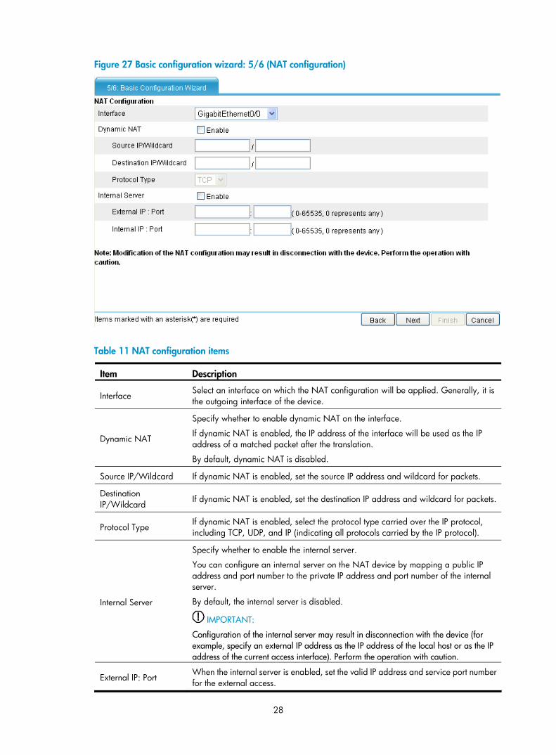
28
Figure 27 Basic configuration wizard: 5/6 (NAT configuration)
Table 11 NAT configuration items
Item Description
Interface Select an interface on which the NAT configuration will be applied. Generally, it is the outgoing interface of the device.
Dynamic NAT
Specify whether to enable dynamic NAT on the interface.
If dynamic NAT is enabled, the IP address of the interface will be used as the IP address of a matched packet after the translation.
By default, dynamic NAT is disabled.
Source IP/Wildcard If dynamic NAT is enabled, set the source IP address and wildcard for packets.
Destination IP/Wildcard If dynamic NAT is enabled, set the destination IP address and wildcard for packets.
Protocol Type If dynamic NAT is enabled, select the protocol type carried over the IP protocol, including TCP, UDP, and IP (indicating all protocols carried by the IP protocol).
Internal Server
Specify whether to enable the internal server.
You can configure an internal server on the NAT device by mapping a public IP address and port number to the private IP address and port number of the internal server.
By default, the internal server is disabled.
IMPORTANT:
Configuration of the internal server may result in disconnection with the device (for example, specify an external IP address as the IP address of the local host or as the IP address of the current access interface). Perform the operation with caution.
External IP: Port When the internal server is enabled, set the valid IP address and service port number for the external access.
29
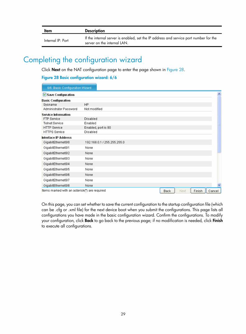
Item Description
Internal IP: Port If the internal server is enabled, set the IP address and service port number for the server on the internal LAN.
Completing the configuration wizard Click Next on the NAT configuration page to enter the page shown in Figure 28.
Figure 28 Basic configuration wizard: 6/6
On this page, you can set whether to save the current configuration to the startup configuration file (which can be .cfg or .xml file) for the next device boot when you submit the configurations. This page lists all configurations you have made in the basic configuration wizard. Confirm the configurations. To modify your configuration, click Back to go back to the previous page; if no modification is needed, click Finish to execute all configurations.
30
Hardware management and maintenance
This chapter includes these sections:
• Displaying detailed information about the firewall
• Displaying software and hardware version information of the firewall
• Displaying the electrical label information of the firewall
• Displaying the CPU usage of the firewall
• Displaying the memory usage of the firewall
• Displaying the operational status of the fans
• Displaying the operational status of a power supply
• Displaying the temperature information of the firewall
• Displaying operational statistics of the firewall
• Saving the running configuration of the firewall
• Rebooting the firewall
NOTE:
The CLI and outputs may vary by the software version. For more information about the commands used inthis chapter, see the command references for the firewalls.
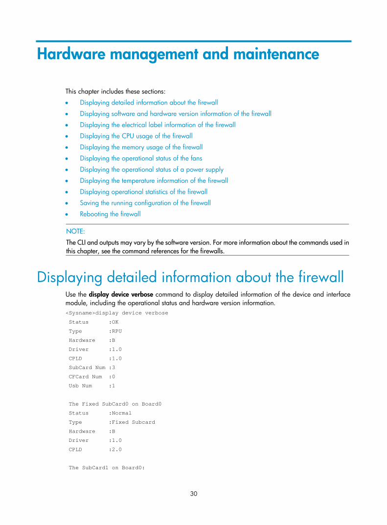
Displaying detailed information about the firewall Use the display device verbose command to display detailed information of the device and interface module, including the operational status and hardware version information. <Sysname>display device verbose
Status :OK
Type :RPU
Hardware :B
Driver :1.0
CPLD :1.0
SubCard Num :3
CFCard Num :0
Usb Num :1
The Fixed SubCard0 on Board0
Status :Normal
Type :Fixed Subcard
Hardware :B
Driver :1.0
CPLD :2.0
The SubCard1 on Board0:
31
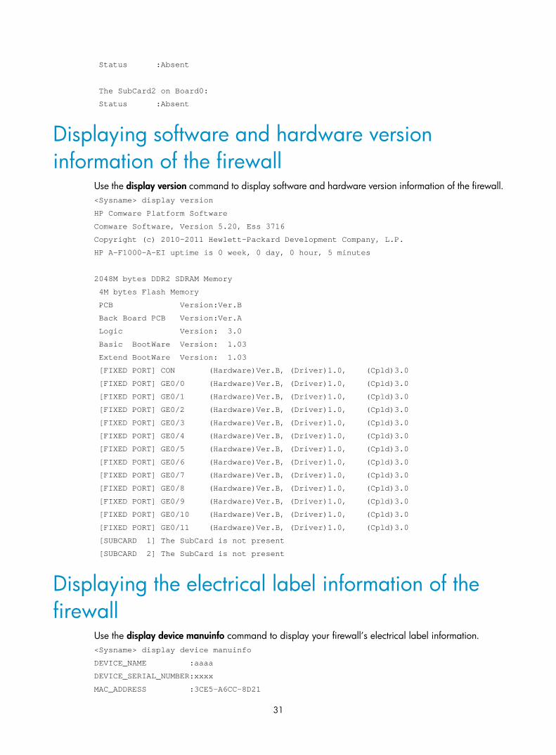
Status :Absent
The SubCard2 on Board0:
Status :Absent
Displaying software and hardware version information of the firewall
Use the display version command to display software and hardware version information of the firewall. <Sysname> display version
HP Comware Platform Software
Comware Software, Version 5.20, Ess 3716
Copyright (c) 2010-2011 Hewlett-Packard Development Company, L.P.
HP A-F1000-A-EI uptime is 0 week, 0 day, 0 hour, 5 minutes
2048M bytes DDR2 SDRAM Memory
4M bytes Flash Memory
PCB Version:Ver.B
Back Board PCB Version:Ver.A
Logic Version: 3.0
Basic BootWare Version: 1.03
Extend BootWare Version: 1.03
[FIXED PORT] CON (Hardware)Ver.B, (Driver)1.0, (Cpld)3.0
[FIXED PORT] GE0/0 (Hardware)Ver.B, (Driver)1.0, (Cpld)3.0
[FIXED PORT] GE0/1 (Hardware)Ver.B, (Driver)1.0, (Cpld)3.0
[FIXED PORT] GE0/2 (Hardware)Ver.B, (Driver)1.0, (Cpld)3.0
[FIXED PORT] GE0/3 (Hardware)Ver.B, (Driver)1.0, (Cpld)3.0
[FIXED PORT] GE0/4 (Hardware)Ver.B, (Driver)1.0, (Cpld)3.0
[FIXED PORT] GE0/5 (Hardware)Ver.B, (Driver)1.0, (Cpld)3.0
[FIXED PORT] GE0/6 (Hardware)Ver.B, (Driver)1.0, (Cpld)3.0
[FIXED PORT] GE0/7 (Hardware)Ver.B, (Driver)1.0, (Cpld)3.0
[FIXED PORT] GE0/8 (Hardware)Ver.B, (Driver)1.0, (Cpld)3.0
[FIXED PORT] GE0/9 (Hardware)Ver.B, (Driver)1.0, (Cpld)3.0
[FIXED PORT] GE0/10 (Hardware)Ver.B, (Driver)1.0, (Cpld)3.0
[FIXED PORT] GE0/11 (Hardware)Ver.B, (Driver)1.0, (Cpld)3.0
[SUBCARD 1] The SubCard is not present
[SUBCARD 2] The SubCard is not present
Displaying the electrical label information of the firewall
Use the display device manuinfo command to display your firewall’s electrical label information. <Sysname> display device manuinfo
DEVICE_NAME :aaaa
DEVICE_SERIAL_NUMBER:xxxx
MAC_ADDRESS :3CE5-A6CC-8D21
32
MANUFACTURING_DATE :2010-06-29
VENDOR_NAME :HP
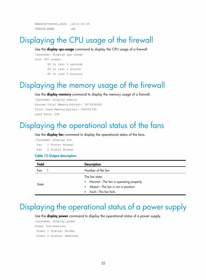
Displaying the CPU usage of the firewall Use the display cpu-usage command to display the CPU usage of a firewall. <Sysname> display cpu-usage
Unit CPU usage:
4% in last 5 seconds
4% in last 1 minute
4% in last 5 minutes
Displaying the memory usage of the firewall Use the display memory command to display the memory usage of a firewall. <Sysname> display memory
System Total Memory(bytes): 1874838960
Total Used Memory(bytes): 546091792
Used Rate: 29%
Displaying the operational status of the fans Use the display fan command to display the operational status of the fans. <Sysname> display fan
Fan 1 State: Normal
Fan 2 State: Normal
Table 12 Output description
Field Description
Fan 1 Number of the fan
State
The fan state: • Normal—The fan is operating properly. • Absent—The fan is not in position. • Fault—The fan fails.
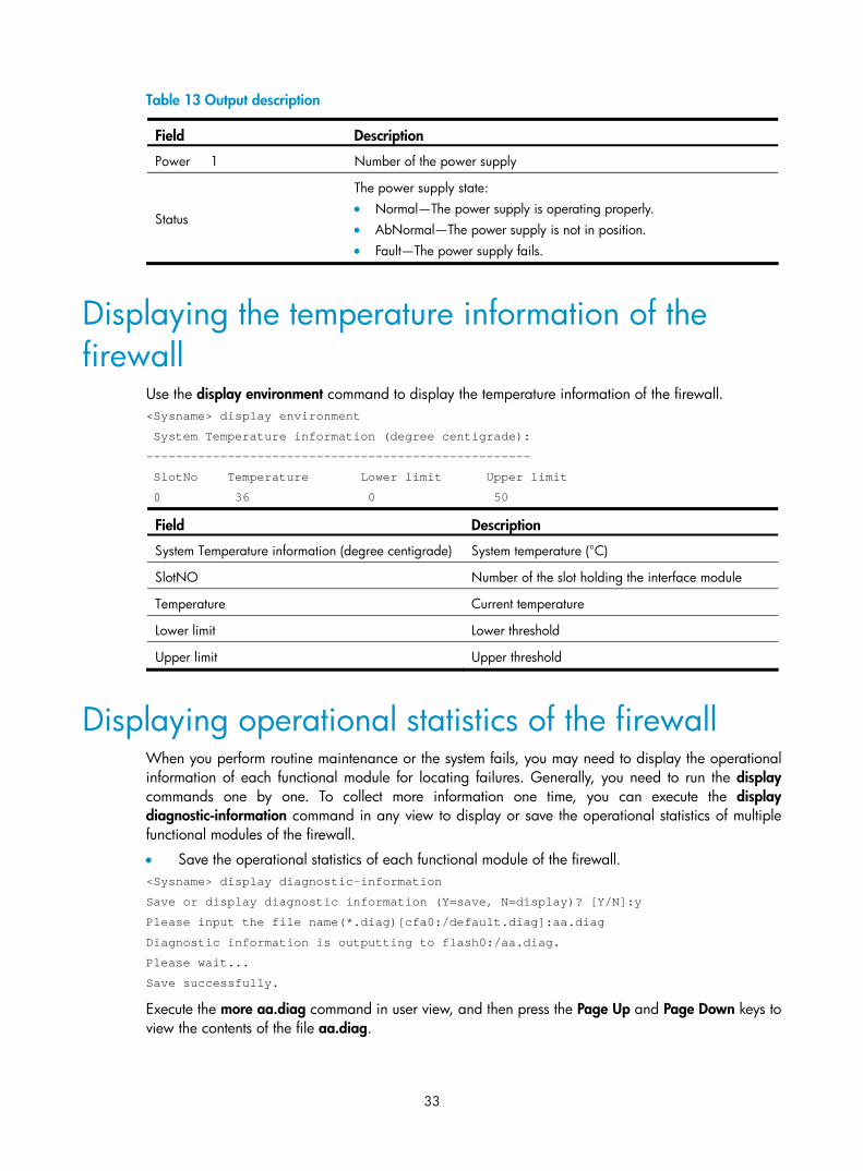
Displaying the operational status of a power supply Use the display power command to display the operational status of a power supply. <Sysname> display power
Power Information:
Power 1 Status: Normal
Power 2 Status: AbNormal
33
Table 13 Output description
Field Description
Power 1 Number of the power supply
Status
The power supply state: • Normal—The power supply is operating properly. • AbNormal—The power supply is not in position. • Fault—The power supply fails.
Displaying the temperature information of the firewall
Use the display environment command to display the temperature information of the firewall. <Sysname> display environment
System Temperature information (degree centigrade):
----------------------------------------------------
SlotNo Temperature Lower limit Upper limit
0 36 0 50
Field Description
System Temperature information (degree centigrade) System temperature (°C)
SlotNO Number of the slot holding the interface module
Temperature Current temperature
Lower limit Lower threshold
Upper limit Upper threshold
Displaying operational statistics of the firewall When you perform routine maintenance or the system fails, you may need to display the operational information of each functional module for locating failures. Generally, you need to run the display commands one by one. To collect more information one time, you can execute the display diagnostic-information command in any view to display or save the operational statistics of multiple functional modules of the firewall.
• Save the operational statistics of each functional module of the firewall. <Sysname> display diagnostic-information
Save or display diagnostic information (Y=save, N=display)? [Y/N]:y
Please input the file name(*.diag)[cfa0:/default.diag]:aa.diag
Diagnostic information is outputting to flash0:/aa.diag.
Please wait...
Save successfully.
Execute the more aa.diag command in user view, and then press the Page Up and Page Down keys to view the contents of the file aa.diag.
34
• Display the operational statistics of each functional module of the firewall. The output is too much and omitted here.
<Sysname> display diagnostic-information
Save or display diagnostic information (Y=save, N=display)? [Y/N]:n
=================================================================
===============running CPU usage information===============
=================================================================
===== Current CPU usage info =====
CPU Usage Stat. Cycle: 25 (Second)
CPU Usage : 10%
CPU Usage Stat. Time : 2011-07-08 15:50:48
CPU Usage Stat. Tick : 0xf(CPU Tick High) 0xaf1d7cba(CPU Tick Low)
Actual Stat. Cycle : 0x0(CPU Tick High) 0x665cbd2a(CPU Tick Low)
Omitted
Saving the running configuration of the firewall You can save the running configuration of the firewall in one of the following modes:
• Fast saving: Executing the save command without the safely keyword. This mode saves the file more quickly but is likely to lose the existing configuration file if the device reboots or the power fails during the process. The fast saving mode is suitable for environments where the power supply is stable.
• Safe saving: Executing the save command with the safely keyword. The mode saves the file more slowly but can retain the configuration file in the device even if the device reboots or the power fails during the process. The safe saving mode is preferred in environments where a stable power supply is unavailable or remote maintenance is involved.
Follow these steps to save the current configuration of the firewall:
To do… Use the command… Remarks
Save the current configuration to the specified file, but the configuration file will not be set as the file for the next startup
save file-url
Save the current configuration to the root directory of the storage medium and specify the file as the startup configuration file that will be used at the next system startup
save [ safely ]
Use either command
Available in any view
NOTE:
• The configuration file must be with extension .cfg.
• During the execution of the save command, the startup configuration file to be used at the next systemstartup may be lost if the device reboots or the power supply fails. In this case, the device will boot withthe factory defaults, and after the device reboots, you need to re-specify a startup configuration file forthe next system startup.
Rebooting the firewall To reboot a firewall, use one of the following methods:
35
• Use the reboot command to reboot a firewall.
• Enable the scheduled reboot function at the CLI. You can set a time at which the firewall can automatically reboot, or set a delay so that the firewall can automatically reboot within the delay.
• Power on the firewall after powering it off, which is also called hard reboot or cold start. Powering off a running firewall causes data loss and hardware damages, and therefore is not recommended.
Perform the following operation to reboot the firewall immediately:
To do… Use the command… Remarks
Reboot the firewall immediately reboot
Required
Available in user view
Perform the following operation to enable the scheduled reboot function:
To do… Use the command… Remarks
Enable the scheduled reboot function and specify a specific reboot time and date
schedule reboot at hh:mm [ date ]
Enable the scheduled reboot function and specify a reboot waiting time
schedule reboot delay { hh:mm | mm }
Use either command
The scheduled reboot function is disabled by default.
Available in user view
CAUTION:
• If the main host software file is not specified, do not use the reboot command to reboot the firewall. Inthis case, you should specify the main host software file first, and then reboot the firewall.
• The precision of the rebooting timer is 1 minute. One minute before the rebooting time, the device prompts “REBOOT IN ONE MINUTE” and reboots in one minute.
• If you are performing file operations when the device is to be rebooted, the system does not execute thereboot command for security.
36
Troubleshooting
This chapter includes these sections:
• Power supply system failure
• Fan failure
• Configuration terminal problems
• Password loss
• Cooling system failure
• Interface module failure
NOTE:
• The barcode stuck on the firewall chassis contains production and servicing information. Before you return a faulty firewall for serving, provide the barcode information of the firewall to your local sales agent.
• Keep the tamper-proof seal on a mounting screw on the chassis cover intact, and if you want to open thechassis, contact the local agent of HP for permission. Otherwise, HP shall not be liable for any consequence caused thereby.
Power supply system failure The firewall cannot be powered on. The power LED on the front panel is off.
Follow these steps to troubleshoot the power supply system:
Step1 Turn off the power switch.
Step2 Check whether the power cord is properly, firmly connected.
Step3 Check whether the power cord is damaged.
If the cause cannot be located in the steps above and the problem persists, contact your local sales agent.
Fan failure After the firewall is booted, the following information appears: %Jun 22 16:11:37:485 2010 HP DEV/4/FAN FAILED:
Fan 1 failed.
If such information appears, you need to open the chassis to check the fan. Contact your local sales agent.
37
Configuration terminal problems If the configuration environment setup is correct, the configuration terminal displays boot information when the firewall is powered on. If the setup is incorrect, the configuration terminal displays nothing or garbled text.
No terminal display If the configuration terminal displays nothing when the firewall is powered on, check the following items:
• The power supply system works properly.
• The console cable is properly connected.
If no problem is found, the following reasons may apply:
• The console cable is connected to an incorrect serial interface (the serial interface in use is not the one set on the terminal).
• The properties of the terminal are incorrect. You must configure the configuration terminal as follows: set Bits per second to 9600, Data bits to 8, Parity to None, Stop bits to 1, Flow control to None, and Terminal Emulation to VT100.
• The console cable is not in good condition.
Garbled terminal display If terminal display is garbled, check that the Data bits field is set to 8 for the configuration terminal.
Password loss When the user password or super password is lost, resort to the following methods:
User password loss If you lose your password, you cannot enter the system. In this case, you can boot the system by ignoring the system configuration. Follow these steps to solve the user password loss:
Step1 Enter the BootWare main menu, and select 6 to boot the system by ignoring the system configuration.
The system prompts the following: Flag Set Success.
The output indicates that the setting succeeded.
Step2 When the BootWare main menu appears again, select 0 to reboot the system. System is starting...
Booting Normal Extend BootWare....
Step3 Set a new password in system view after the system reboots. <Sysname> system-view
[Sysname] user-interface console 0
[Sysname-ui-console0] authentication-mode password
[Sysname-ui-console0] set authentication password simple 123456
The output shows that the console port uses password authentication, and the password is set to 123456 and stored in plain text.
38
When you set the password by using the set authentication password { cipher | simple } password command, follow these guidelines.
• If the cipher keyword is specified, the password is stored in cipher text. You cannot view the password by using the display current-configuration command.
• If the simple keyword is specified, the password is stored in plain text. You can use the display current-configuration command to view the password in the current configuration.
NOTE:
After the firewall reboots, the system runs with the initial default configuration, but the previous configuration file is still stored in the storage medium. To restore the previous configuration, use the display saved-configuration command to display the configuration, and then copy and execute the configuration.
Step4 Save the new password. [Sysname] save
NOTE:
• To save the new password, execute the save command after modifying the user password.
• HP recommends saving the modification as the default configuration file.
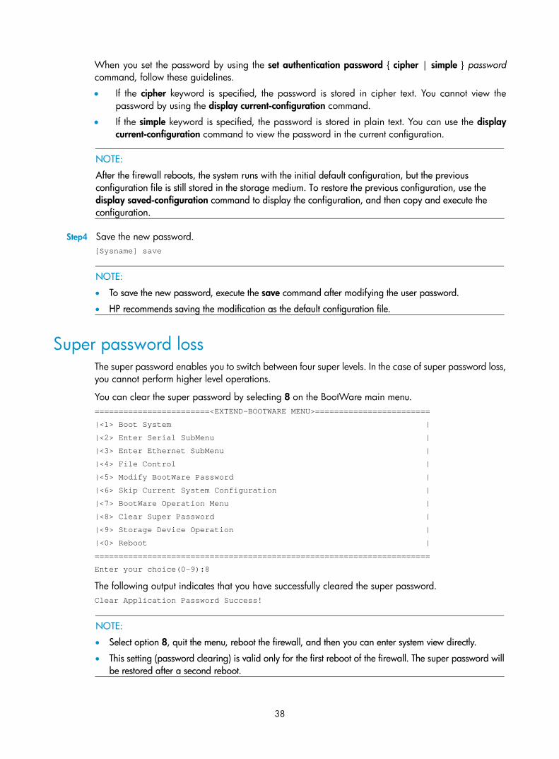
Super password loss The super password enables you to switch between four super levels. In the case of super password loss, you cannot perform higher level operations.
You can clear the super password by selecting 8 on the BootWare main menu. ========================<EXTEND-BOOTWARE MENU>========================
|<1> Boot System |
|<2> Enter Serial SubMenu |
|<3> Enter Ethernet SubMenu |
|<4> File Control |
|<5> Modify BootWare Password |
|<6> Skip Current System Configuration |
|<7> BootWare Operation Menu |
|<8> Clear Super Password |
|<9> Storage Device Operation |
|<0> Reboot |
======================================================================
Enter your choice(0-9):8
The following output indicates that you have successfully cleared the super password. Clear Application Password Success!
NOTE:
• Select option 8, quit the menu, reboot the firewall, and then you can enter system view directly.
• This setting (password clearing) is valid only for the first reboot of the firewall. The super password willbe restored after a second reboot.
39
Cooling system failure When the temperature inside the firewall exceeds 45°C (113°F), the cooling system may have failed.
Follow these steps to troubleshoot the cooling system:
Step1 Check whether the fans are running properly.
Step2 Check whether the working environment of the firewall is well ventilated.
Step3 If the temperature inside the firewall exceeds 60°C (140°F), the following information appears on the configuration terminal: %May 19 19:38:59:134 2011 HP DRVMSG/3/Temp2High:Temperature Point 0/0 Too High.
#May 19 19:39:03:227 2011 HP DEV/1/BOARD TEMPERATURE UPPER:
Trap 1.3.6.1.4.1.25506.8.35.12.1.16: chassisIndex is 0, slotIndex 0.0
%May 19 19:39:03:228 2011 HP DEV/4/BOARD TEMP TOOHIGH:
Board temperature is too high on Chassis 0 Slot 0, type is RPU.
Step4 Use the display environment command to check whether the temperature in the firewall keeps rising. If the temperature inside the firewall exceeds 90°C (194°F), power off the firewall immediately and contact your local sales agent.
Interface module failure After an interface module is installed and the firewall is powered on, the LEDs on the interface module panel indicate abnormal operation.
Follow these steps to solve this problem:
Step1 Check whether the interface module cable is correctly selected.
Step2 Check whether the interface module cable is correctly connected.
Step3 Use the display interface command to check whether the interface has been correctly configured and is working properly.
40
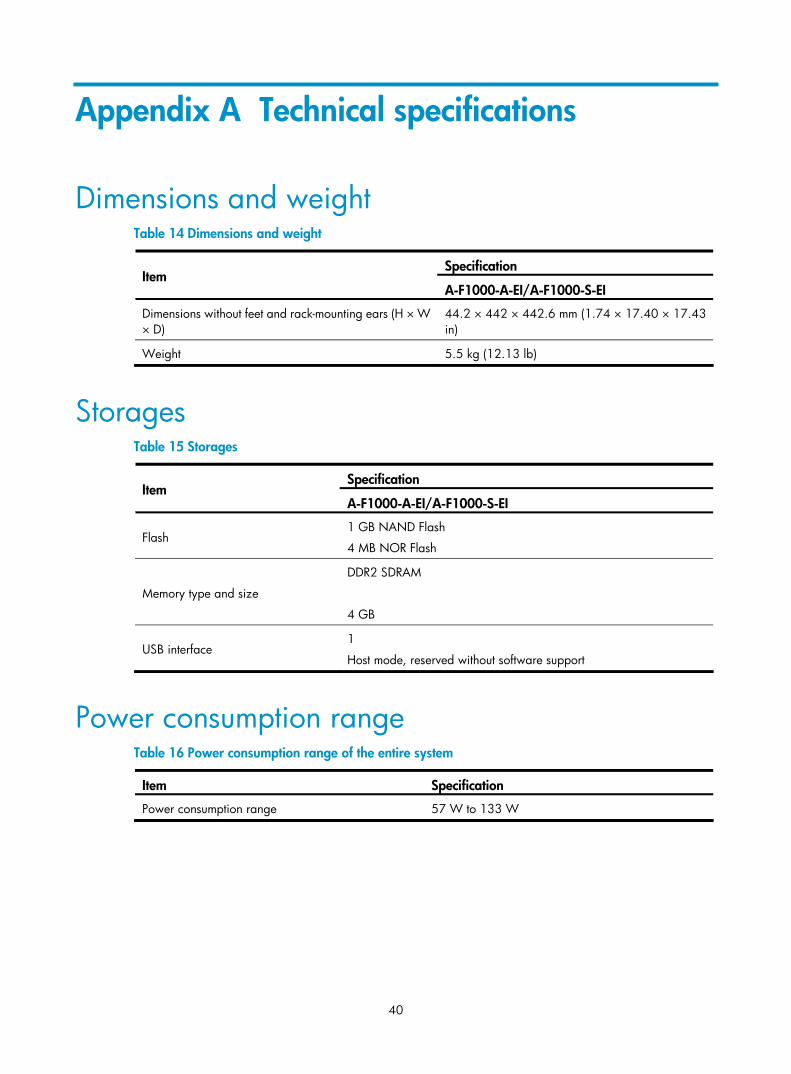
Appendix A Technical specifications
Dimensions and weight Table 14 Dimensions and weight
Specification Item
A-F1000-A-EI/A-F1000-S-EI
Dimensions without feet and rack-mounting ears (H × W × D)
44.2 × 442 × 442.6 mm (1.74 × 17.40 × 17.43 in)
Weight 5.5 kg (12.13 lb)
Storages Table 15 Storages
Specification Item
A-F1000-A-EI/A-F1000-S-EI
Flash 1 GB NAND Flash
4 MB NOR Flash
Memory type and size
DDR2 SDRAM
4 GB
USB interface 1
Host mode, reserved without software support
Power consumption range Table 16 Power consumption range of the entire system
Item Specification
Power consumption range 57 W to 133 W
41
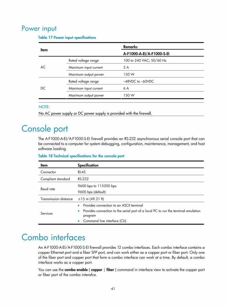
Power input Table 17 Power input specifications
Remarks Item
A-F1000-A-EI/A-F1000-S-EI
Rated voltage range 100 to 240 VAC; 50/60 Hz
Maximum input current 2 A AC
Maximum output power 150 W
Rated voltage range –48VDC to –60VDC
Maximum input current 6 A DC
Maximum output power 150 W
NOTE:
No AC power supply or DC power supply is provided with the firewall.
Console port The A-F1000-A-EI/A-F1000-S-EI firewall provides an RS-232 asynchronous serial console port that can be connected to a computer for system debugging, configuration, maintenance, management, and host software loading.
Table 18 Technical specifications for the console port
Item Specification
Connector RJ-45
Compliant standard RS-232
Baud rate 9600 bps to 115200 bps
9600 bps (default)
Transmission distance ≤15 m (49.21 ft)
Services
• Provides connection to an ASCII terminal • Provides connection to the serial port of a local PC to run the terminal emulation
program • Command line interface (CLI)
Combo interfaces An A-F1000-A-EI/A-F1000-S-EI firewall provides 12 combo interfaces. Each combo interface contains a copper Ethernet port and a fiber SFP port, and can work either as a copper port or fiber port. Only one of the fiber port and copper port that form a combo interface can work at a time. By default, a combo interface works as a copper port.
You can use the combo enable { copper | fiber } command in interface view to activate the copper port or fiber port of the combo interafce.
42
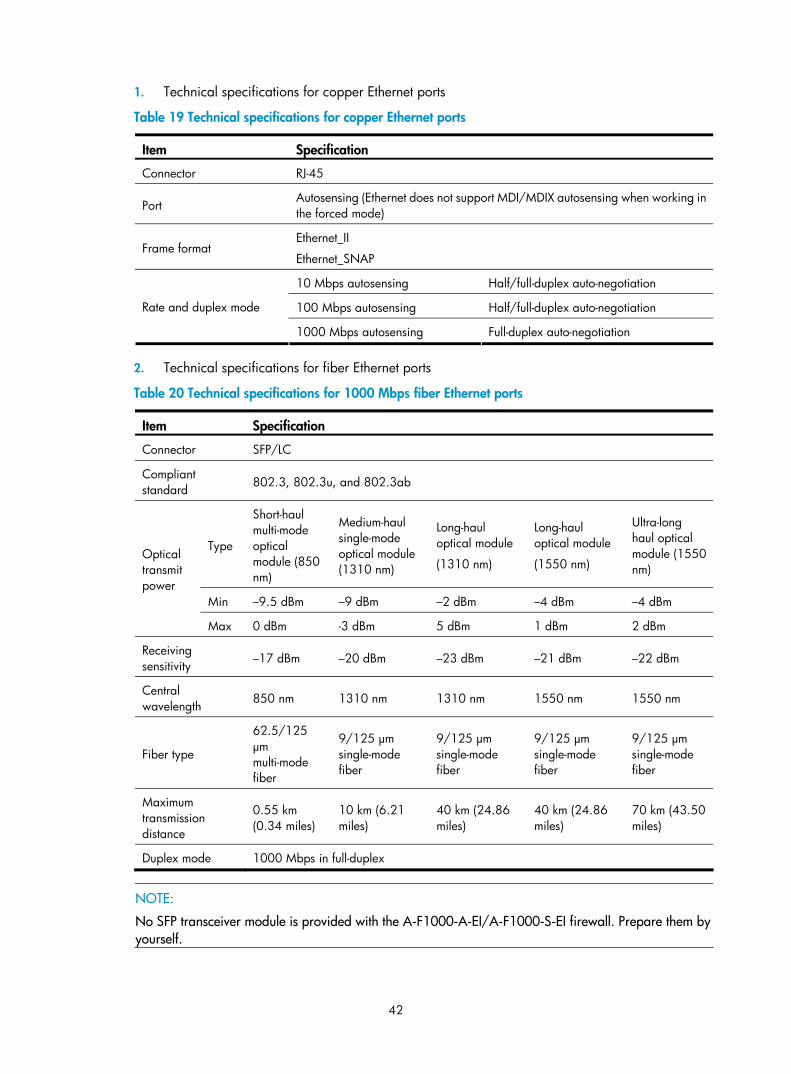
1. Technical specifications for copper Ethernet ports
Table 19 Technical specifications for copper Ethernet ports
Item Specification
Connector RJ-45
Port Autosensing (Ethernet does not support MDI/MDIX autosensing when working in the forced mode)
Frame format Ethernet_II
Ethernet_SNAP
10 Mbps autosensing Half/full-duplex auto-negotiation
100 Mbps autosensing Half/full-duplex auto-negotiation Rate and duplex mode
1000 Mbps autosensing Full-duplex auto-negotiation
2. Technical specifications for fiber Ethernet ports
Table 20 Technical specifications for 1000 Mbps fiber Ethernet ports
Item Specification
Connector SFP/LC
Compliant standard 802.3, 802.3u, and 802.3ab
Type
Short-haul multi-mode optical module (850 nm)
Medium-haul single-mode optical module (1310 nm)
Long-haul optical module
(1310 nm)
Long-haul optical module
(1550 nm)
Ultra-long haul optical module (1550 nm)
Min –9.5 dBm –9 dBm –2 dBm –4 dBm –4 dBm
Optical transmit power
Max 0 dBm -3 dBm 5 dBm 1 dBm 2 dBm
Receiving sensitivity –17 dBm –20 dBm –23 dBm –21 dBm –22 dBm
Central wavelength 850 nm 1310 nm 1310 nm 1550 nm 1550 nm
Fiber type
62.5/125 μm multi-mode fiber
9/125 μm single-mode fiber
9/125 μm single-mode fiber
9/125 μm single-mode fiber
9/125 μm single-mode fiber
Maximum transmission distance
0.55 km (0.34 miles)
10 km (6.21 miles)
40 km (24.86 miles)
40 km (24.86 miles)
70 km (43.50 miles)
Duplex mode 1000 Mbps in full-duplex
NOTE:
No SFP transceiver module is provided with the A-F1000-A-EI/A-F1000-S-EI firewall. Prepare them by yourself.
43
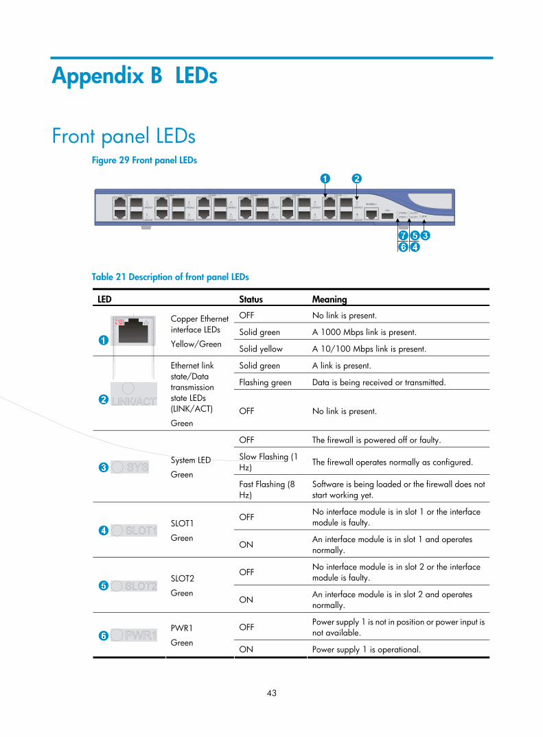
Appendix B LEDs
Front panel LEDs Figure 29 Front panel LEDs
Table 21 Description of front panel LEDs
LED Status Meaning
OFF No link is present.
Solid green A 1000 Mbps link is present.
Copper Ethernet interface LEDs
Yellow/Green Solid yellow A 10/100 Mbps link is present.
Solid green A link is present.
Flashing green Data is being received or transmitted.
Ethernet link state/Data transmission state LEDs (LINK/ACT)
Green OFF No link is present.
OFF The firewall is powered off or faulty.
Slow Flashing (1 Hz)
The firewall operates normally as configured.
System LED
Green Fast Flashing (8 Hz)
Software is being loaded or the firewall does not start working yet.
OFF No interface module is in slot 1 or the interface module is faulty.
SLOT1
Green ON
An interface module is in slot 1 and operates normally.
OFF No interface module is in slot 2 or the interface module is faulty.
SLOT2
Green ON
An interface module is in slot 2 and operates normally.
OFF Power supply 1 is not in position or power input is not available.
PWR1
Green ON Power supply 1 is operational.

44
LED Status Meaning
OFF Power supply 2 is not in position or power input is not available.
PWR2
Green ON Power supply 2 is operational.
45
Appendix C Interface module
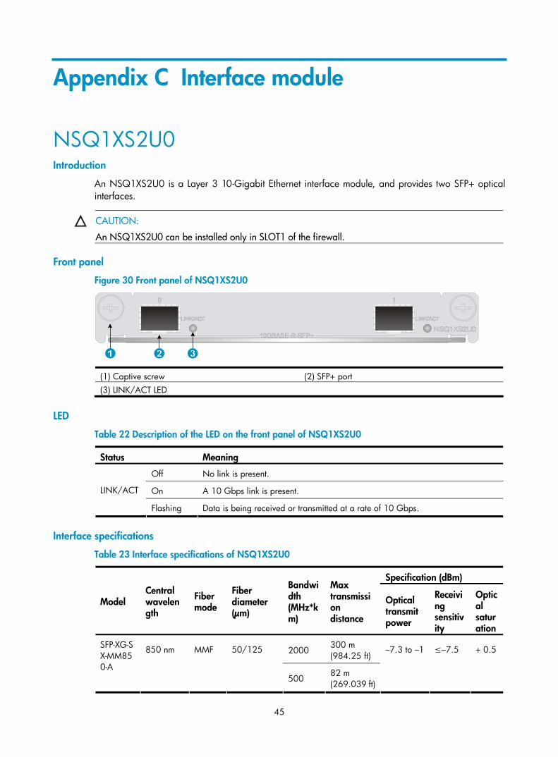
NSQ1XS2U0 Introduction
An NSQ1XS2U0 is a Layer 3 10-Gigabit Ethernet interface module, and provides two SFP+ optical interfaces.
CAUTION:
An NSQ1XS2U0 can be installed only in SLOT1 of the firewall.
Front panel
Figure 30 Front panel of NSQ1XS2U0
(1) Captive screw (2) SFP+ port (3) LINK/ACT LED
LED
Table 22 Description of the LED on the front panel of NSQ1XS2U0
Status Meaning
Off No link is present.
On A 10 Gbps link is present. LINK/ACT
Flashing Data is being received or transmitted at a rate of 10 Gbps.
Interface specifications
Table 23 Interface specifications of NSQ1XS2U0
Specification (dBm)
Model Central wavelength
Fiber mode
Fiber diameter (μm)
Bandwidth (MHz*km)
Max transmission distance
Optical transmit power
Receiving sensitivity
Optical saturation
2000 300 m (984.25 ft)
SFP-XG-SX-MM850-A
850 nm MMF 50/125
500 82 m (269.039 ft)
–7.3 to –1 ≤–7.5 + 0.5
46
Specification (dBm)
Model Central wavelength
Fiber mode
Fiber diameter (μm)
Bandwidth (MHz*km)
Max transmission distance
Optical transmit power
Receiving sensitivity
Optical saturation
400 66 m (216.54 ft)
200 33 m (108.27 ft)
62.5/125
160 26 m (85.30 ft)
62.5/125 500 220 m (721.79 ft)
500 220 m (721.79 ft)
SFP-XG-LX220-MM1310
MMF
50/125
400 100 m (328.08 ft)
–6.5 to +0.5 ≤–6.5 +1.5
SFP-XG-LX-SM1310
1310 nm
SMF 9/125 — 10 km (6.21 miles)
–8.2 to + 0.5 ≤–10.3 + 0.5
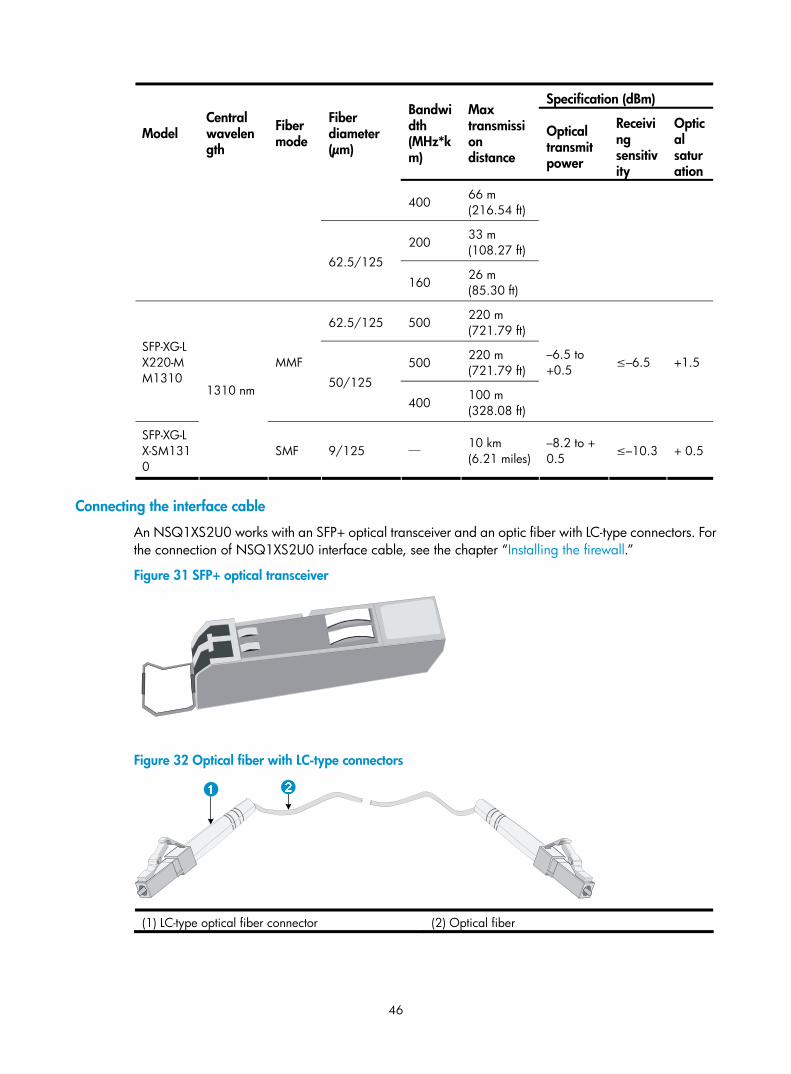
Connecting the interface cable
An NSQ1XS2U0 works with an SFP+ optical transceiver and an optic fiber with LC-type connectors. For the connection of NSQ1XS2U0 interface cable, see the chapter “Installing the firewall.”
Figure 31 SFP+ optical transceiver
Figure 32 Optical fiber with LC-type connectors
(1) LC-type optical fiber connector (2) Optical fiber
47
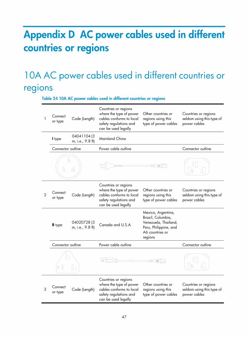
Appendix D AC power cables used in different countries or regions
10A AC power cables used in different countries or regions
Table 24 10A AC power cables used in different countries or regions
1 Connector type Code (Length)
Countries or regions where the type of power cables conforms to local safety regulations and can be used legally
Other countries or regions using this type of power cables
Countries or regions seldom using this type of power cables
I type 04041104 (3 m, i.e., 9.8 ft) Mainland China
Connector outline Power cable outline Connector outline
2 Connector type Code (Length)
Countries or regions where the type of power cables conforms to local safety regulations and can be used legally
Other countries or regions using this type of power cables
Countries or regions seldom using this type of power cables
B type 04020728 (3 m, i.e., 9.8 ft) Canada and U.S.A
Mexico, Argentina, Brazil, Columbia, Venezuela, Thailand, Peru, Philippine, and A6 countries or regions
Connector outline Power cable outline Connector outline
3 Connector type Code (Length)
Countries or regions where the type of power cables conforms to local safety regulations and can be used legally
Other countries or regions using this type of power cables
Countries or regions seldom using this type of power cables
48
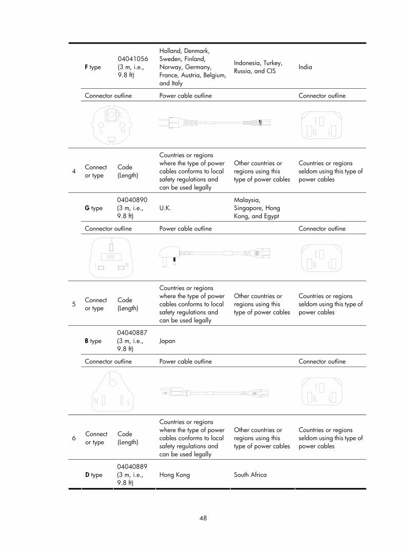
F type 04041056 (3 m, i.e., 9.8 ft)
Holland, Denmark, Sweden, Finland, Norway, Germany, France, Austria, Belgium, and Italy
Indonesia, Turkey, Russia, and CIS India
Connector outline Power cable outline Connector outline
4 Connector type
Code (Length)
Countries or regions where the type of power cables conforms to local safety regulations and can be used legally
Other countries or regions using this type of power cables
Countries or regions seldom using this type of power cables
G type 04040890 (3 m, i.e., 9.8 ft)
U.K. Malaysia, Singapore, Hong Kong, and Egypt
Connector outline Power cable outline Connector outline
5 Connector type
Code (Length)
Countries or regions where the type of power cables conforms to local safety regulations and can be used legally
Other countries or regions using this type of power cables
Countries or regions seldom using this type of power cables
B type 04040887 (3 m, i.e., 9.8 ft)
Japan
Connector outline Power cable outline Connector outline
6 Connector type
Code (Length)
Countries or regions where the type of power cables conforms to local safety regulations and can be used legally
Other countries or regions using this type of power cables
Countries or regions seldom using this type of power cables
D type 04040889 (3 m, i.e., 9.8 ft)
Hong Kong South Africa
49
Connector outline Power cable outline Connector outline
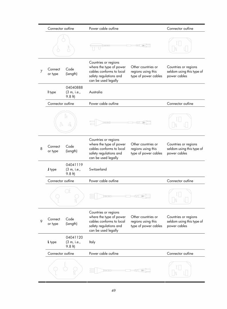
7 Connector type
Code (Length)
Countries or regions where the type of power cables conforms to local safety regulations and can be used legally
Other countries or regions using this type of power cables
Countries or regions seldom using this type of power cables
I type 04040888 (3 m, i.e., 9.8 ft)
Australia
Connector outline Power cable outline Connector outline
8 Connector type
Code (Length)
Countries or regions where the type of power cables conforms to local safety regulations and can be used legally
Other countries or regions using this type of power cables
Countries or regions seldom using this type of power cables
J type 04041119 (3 m, i.e., 9.8 ft)
Switzerland
Connector outline Power cable outline Connector outline
9 Connector type
Code (Length)
Countries or regions where the type of power cables conforms to local safety regulations and can be used legally
Other countries or regions using this type of power cables
Countries or regions seldom using this type of power cables
L type 04041120 (3 m, i.e., 9.8 ft)
Italy
Connector outline Power cable outline Connector outline
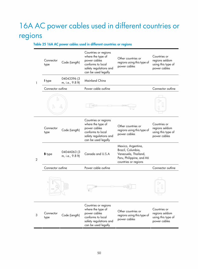
50
16A AC power cables used in different countries or regions
Table 25 16A AC power cables used in different countries or regions
Connector type Code (Length)
Countries or regions where the type of power cables conforms to local safety regulations and can be used legally
Other countries or regions using this type of power cables
Countries or regions seldom using this type of power cables
I type 04043396 (3 m, i.e., 9.8 ft) Mainland China
Connector outline Power cable outline Connector outline
1
Connector type Code (Length)
Countries or regions where the type of power cables conforms to local safety regulations and can be used legally
Other countries or regions using this type of power cables
Countries or regions seldom using this type of power cables
B type 0404A063 (3 m, i.e., 9.8 ft) Canada and U.S.A
Mexico, Argentina, Brazil, Columbia, Venezuela, Thailand, Peru, Philippine, and A6 countries or regions
Connector outline Power cable outline Connector outline
2
3 Connector type Code (Length)
Countries or regions where the type of power cables conforms to local safety regulations and can be used legally
Other countries or regions using this type of power cables
Countries or regions seldom using this type of power cables
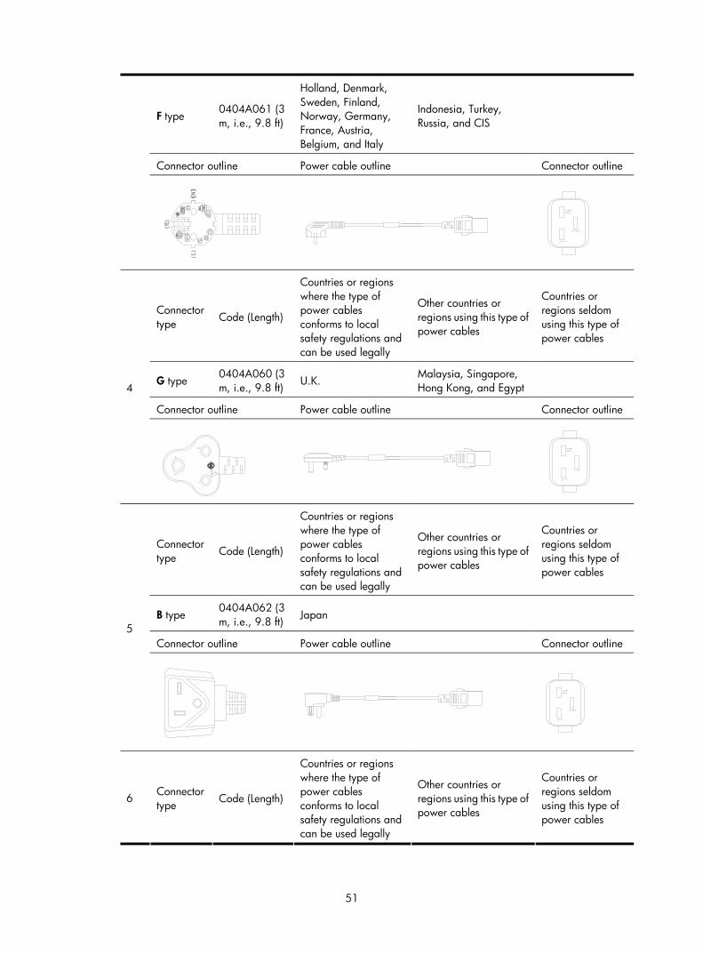
51
F type 0404A061 (3 m, i.e., 9.8 ft)
Holland, Denmark, Sweden, Finland, Norway, Germany, France, Austria, Belgium, and Italy
Indonesia, Turkey, Russia, and CIS
Connector outline Power cable outline Connector outline
Connector type Code (Length)
Countries or regions where the type of power cables conforms to local safety regulations and can be used legally
Other countries or regions using this type of power cables
Countries or regions seldom using this type of power cables
G type 0404A060 (3 m, i.e., 9.8 ft) U.K.
Malaysia, Singapore, Hong Kong, and Egypt
Connector outline Power cable outline Connector outline
4
Connector type Code (Length)
Countries or regions where the type of power cables conforms to local safety regulations and can be used legally
Other countries or regions using this type of power cables
Countries or regions seldom using this type of power cables
B type 0404A062 (3 m, i.e., 9.8 ft) Japan
Connector outline Power cable outline Connector outline 5
6 Connector type Code (Length)
Countries or regions where the type of power cables conforms to local safety regulations and can be used legally
Other countries or regions using this type of power cables
Countries or regions seldom using this type of power cables

52
I type 0404A01A (3 m, i.e., 9.8 ft)
Australia
Connector outline Power cable outline Connector outline
53
Support and other resources
Contacting HP For worldwide technical support information, see the HP support website:
http://www.hp.com/support
Before contacting HP, collect the following information:
• Product model names and numbers
• Technical support registration number (if applicable)
• Product serial numbers
• Error messages
• Operating system type and revision level
• Detailed questions
Subscription service HP recommends that you register your product at the Subscriber's Choice for Business website:
http://www.hp.com/go/wwalerts
After registering, you will receive email notification of product enhancements, new driver versions, firmware updates, and other product resources.
Related information
Documents To find related documents, browse to the Manuals page of the HP Business Support Center website:
http://www.hp.com/support/manuals
• For related documentation, navigate to the Networking section, and select a networking category.
• For a complete list of acronyms and their definitions, see HP A-Series Acronyms.
Websites • HP.com http://www.hp.com
• HP Networking http://www.hp.com/go/networking
• HP manuals http://www.hp.com/support/manuals
• HP download drivers and software http://www.hp.com/support/downloads
• HP software depot http://www.software.hp.com
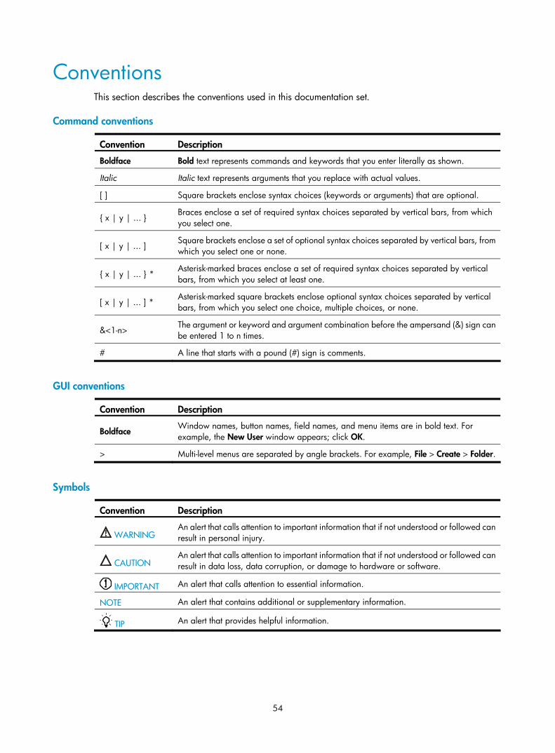
54
Conventions This section describes the conventions used in this documentation set.
Command conventions
Convention Description
Boldface Bold text represents commands and keywords that you enter literally as shown.
Italic Italic text represents arguments that you replace with actual values.
[ ] Square brackets enclose syntax choices (keywords or arguments) that are optional.
{ x | y | ... } Braces enclose a set of required syntax choices separated by vertical bars, from which you select one.
[ x | y | ... ] Square brackets enclose a set of optional syntax choices separated by vertical bars, from which you select one or none.
{ x | y | ... } * Asterisk-marked braces enclose a set of required syntax choices separated by vertical bars, from which you select at least one.
[ x | y | ... ] * Asterisk-marked square brackets enclose optional syntax choices separated by vertical bars, from which you select one choice, multiple choices, or none.
&<1-n> The argument or keyword and argument combination before the ampersand (&) sign can be entered 1 to n times.
# A line that starts with a pound (#) sign is comments.
GUI conventions
Convention Description
Boldface Window names, button names, field names, and menu items are in bold text. For example, the New User window appears; click OK.
> Multi-level menus are separated by angle brackets. For example, File > Create > Folder.
Symbols
Convention Description
WARNING An alert that calls attention to important information that if not understood or followed can result in personal injury.
CAUTION An alert that calls attention to important information that if not understood or followed can result in data loss, data corruption, or damage to hardware or software.
IMPORTANT An alert that calls attention to essential information.
NOTE An alert that contains additional or supplementary information.
TIP An alert that provides helpful information.
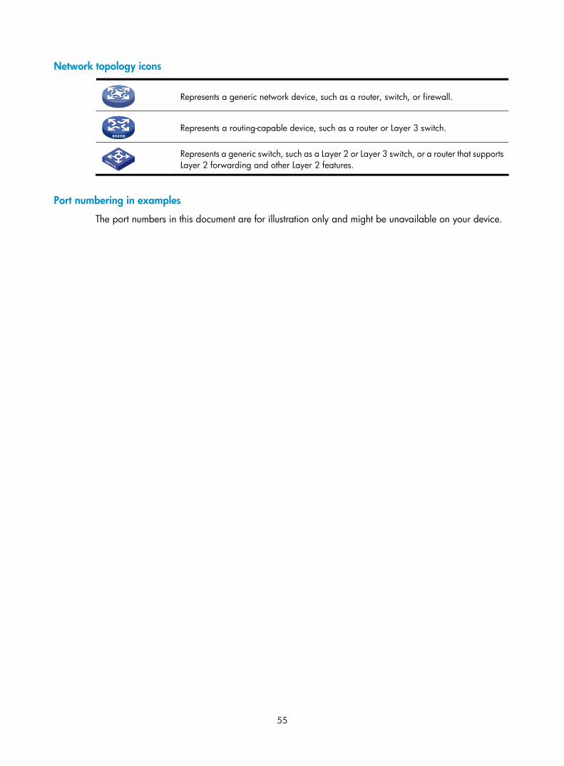
55
Network topology icons
Represents a generic network device, such as a router, switch, or firewall.
Represents a routing-capable device, such as a router or Layer 3 switch.
Represents a generic switch, such as a Layer 2 or Layer 3 switch, or a router that supports Layer 2 forwarding and other Layer 2 features.
Port numbering in examples
The port numbers in this document are for illustration only and might be unavailable on your device.
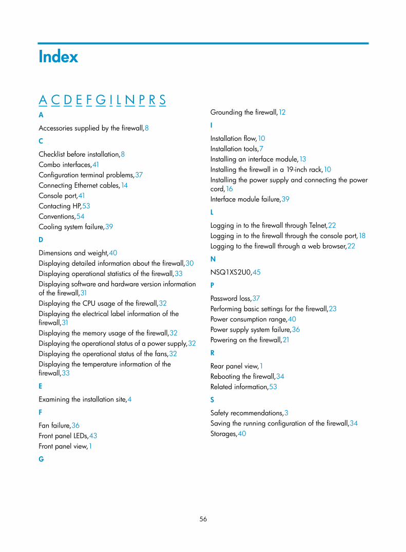
56
Index
A C D E F G I L N P R S A
Accessories supplied by the firewall,8
C
Checklist before installation,8 Combo interfaces,41 Configuration terminal problems,37 Connecting Ethernet cables,14 Console port,41 Contacting HP,53 Conventions,54 Cooling system failure,39
D
Dimensions and weight,40 Displaying detailed information about the firewall,30 Displaying operational statistics of the firewall,33 Displaying software and hardware version information of the firewall,31 Displaying the CPU usage of the firewall,32 Displaying the electrical label information of the firewall,31 Displaying the memory usage of the firewall,32 Displaying the operational status of a power supply,32 Displaying the operational status of the fans,32 Displaying the temperature information of the firewall,33
E
Examining the installation site,4
F
Fan failure,36 Front panel LEDs,43 Front panel view,1
G
Grounding the firewall,12
I
Installation flow,10 Installation tools,7 Installing an interface module,13 Installing the firewall in a 19-inch rack,10 Installing the power supply and connecting the power cord,16 Interface module failure,39
L
Logging in to the firewall through Telnet,22 Logging in to the firewall through the console port,18 Logging to the firewall through a web browser,22
N
NSQ1XS2U0,45
P
Password loss,37 Performing basic settings for the firewall,23 Power consumption range,40 Power supply system failure,36 Powering on the firewall,21
R
Rear panel view,1 Rebooting the firewall,34 Related information,53
S
Safety recommendations,3 Saving the running configuration of the firewall,34 Storages,40