Embed Size (px)
Citation preview
1
INSTALLATION INSTRUCTIONS Electric Model
REV_05 19/04/2016
HEKOS srl Via meassa, 279 32100 Belluno (BL) - ITALY
tel. +39 0437 999647 fax +39 0437 999849
www.hekos.com
2
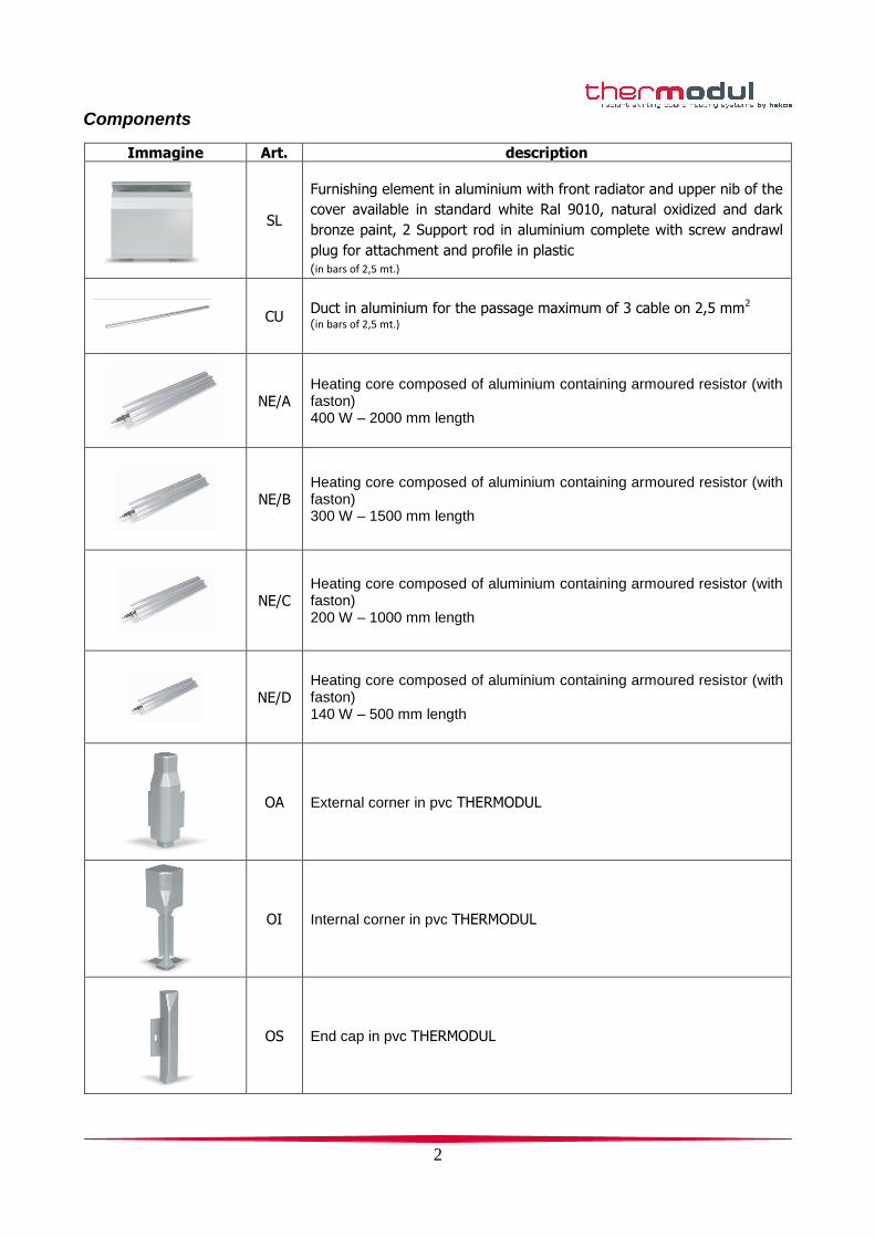
Components
Immagine Art. description
SL
Furnishing element in aluminium with front radiator and upper nib of the
cover available in standard white Ral 9010, natural oxidized and dark
bronze paint, 2 Support rod in aluminium complete with screw andrawl
plug for attachment and profile in plastic (in bars of 2,5 mt.)
CU
Duct in aluminium for the passage maximum of 3 cable on 2,5 mm2 (in bars of 2,5 mt.)
NE/A Heating core composed of aluminium containing armoured resistor (with faston) 400 W – 2000 mm length
NE/B Heating core composed of aluminium containing armoured resistor (with faston) 300 W – 1500 mm length
NE/C Heating core composed of aluminium containing armoured resistor (with faston) 200 W – 1000 mm length
NE/D Heating core composed of aluminium containing armoured resistor (with faston) 140 W – 500 mm length
OA External corner in pvc THERMODUL
OI Internal corner in pvc THERMODUL
OS End cap in pvc THERMODUL
3
Preparation before installing
Preparation before installing
Preparation before installing
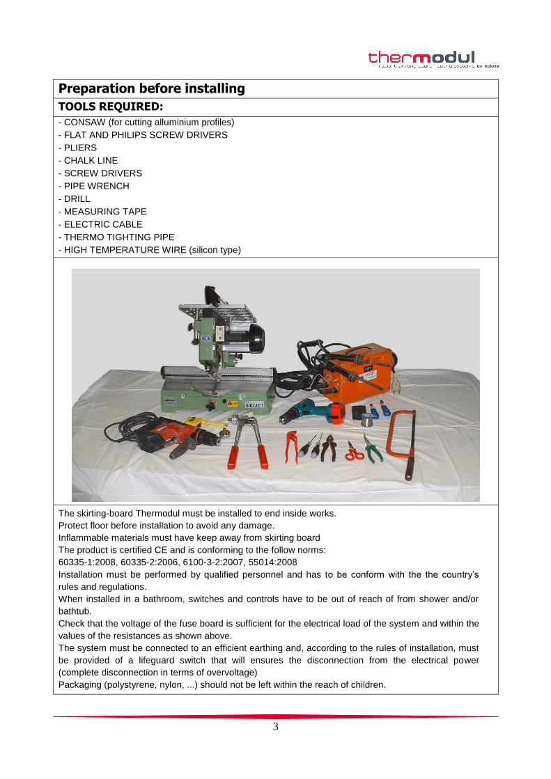
TOOLS REQUIRED:
- CONSAW (for cutting alluminium profiles)
- FLAT AND PHILIPS SCREW DRIVERS
- PLIERS
- CHALK LINE
- SCREW DRIVERS
- PIPE WRENCH
- DRILL
- MEASURING TAPE
- ELECTRIC CABLE
- THERMO TIGHTING PIPE
- HIGH TEMPERATURE WIRE (silicon type)
The skirting-board Thermodul must be installed to end inside works.
Protect floor before installation to avoid any damage.
Inflammable materials must have keep away from skirting board
The product is certified CE and is conforming to the follow norms:
60335-1:2008, 60335-2:2006, 6100-3-2:2007, 55014:2008
Installation must be performed by qualified personnel and has to be conform with the the country’s
rules and regulations.
When installed in a bathroom, switches and controls have to be out of reach of from shower and/or
bathtub.
Check that the voltage of the fuse board is sufficient for the electrical load of the system and within the
values of the resistances as shown above.
The system must be connected to an efficient earthing and, according to the rules of installation, must
be provided of a lifeguard switch that will ensures the disconnection from the electrical power
(complete disconnection in terms of overvoltage)
Packaging (polystyrene, nylon, ...) should not be left within the reach of children.
4
Installation stages
INSTALLATION OF THERMODUL SYSTEM HAPPENS IN 5 STAGES
F1 FIX BRACKETS - pag 5
F2 INSTALLING THE HEATING CORE - pag 6
F3
PLACEMENT OF PROFILES AND PVC COMPONENTS (OS, OI, OA) - pag 7
F4 ELECTRICAL CONNECTIONS - pag 8
F5 INSTALLING THE SKIRTING UNIT - pag 9
IMPORTANT INFORMATION FOR A PROPER INSTALLATION: Handle the material, especially the heating core, with extreme care.
Be aware not to damage the resistors or bend the bars
5
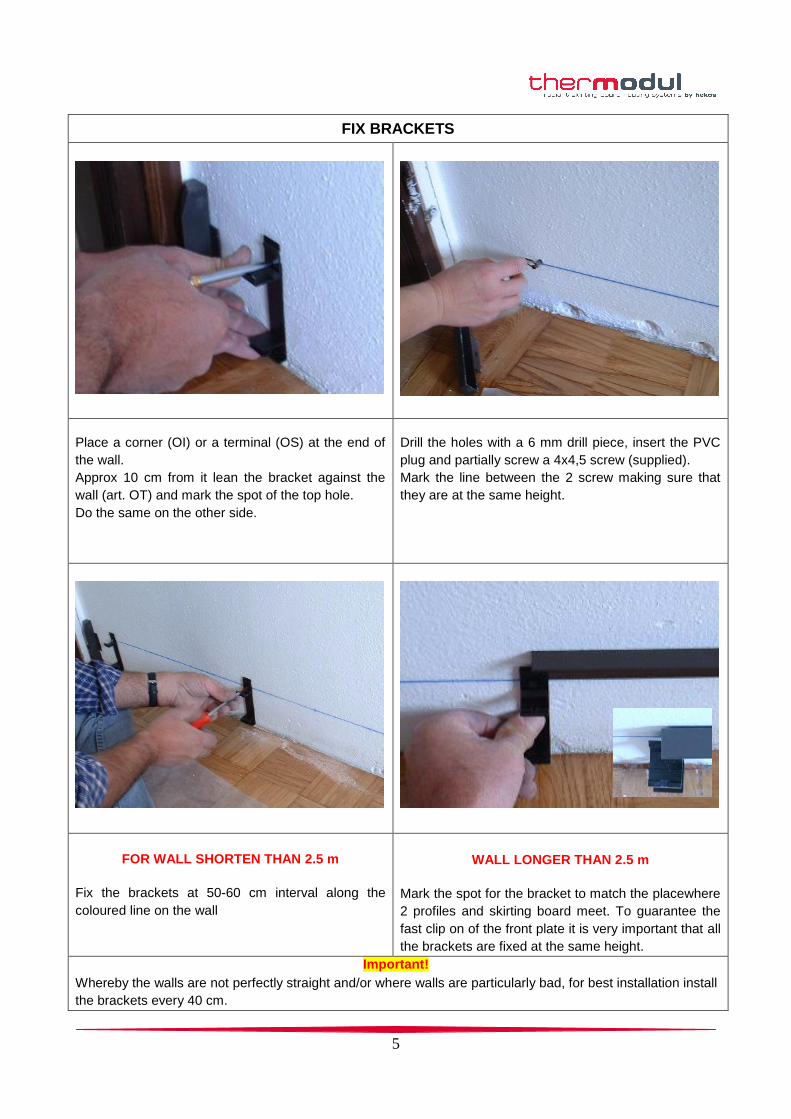
FIX BRACKETS
Place a corner (OI) or a terminal (OS) at the end of
the wall.
Approx 10 cm from it lean the bracket against the
wall (art. OT) and mark the spot of the top hole.
Do the same on the other side.
Drill the holes with a 6 mm drill piece, insert the PVC
plug and partially screw a 4x4,5 screw (supplied).
Mark the line between the 2 screw making sure that
they are at the same height.
FOR WALL SHORTEN THAN 2.5 m
Fix the brackets at 50-60 cm interval along the
coloured line on the wall
WALL LONGER THAN 2.5 m
Mark the spot for the bracket to match the placewhere
2 profiles and skirting board meet. To guarantee the
fast clip on of the front plate it is very important that all
the brackets are fixed at the same height.
Important!
Whereby the walls are not perfectly straight and/or where walls are particularly bad, for best installation install
the brackets every 40 cm.
6
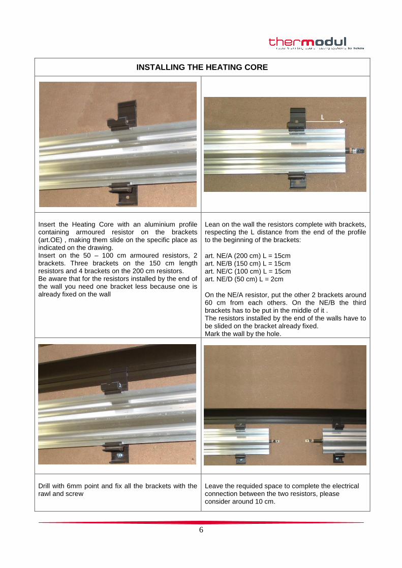
INSTALLING THE HEATING CORE
L
Insert the Heating Core with an aluminium profile containing armoured resistor on the brackets (art.OE) , making them slide on the specific place as indicated on the drawing. Insert on the 50 – 100 cm armoured resistors, 2 brackets. Three brackets on the 150 cm length resistors and 4 brackets on the 200 cm resistors. Be aware that for the resistors installed by the end of the wall you need one bracket less because one is already fixed on the wall
Lean on the wall the resistors complete with brackets, respecting the L distance from the end of the profile to the beginning of the brackets:
art. NE/A (200 cm) L = 15cm art. NE/B (150 cm) L = 15cm art. NE/C (100 cm) L = 15cm art. NE/D (50 cm) L = 2cm
On the NE/A resistor, put the other 2 brackets around 60 cm from each others. On the NE/B the third brackets has to be put in the middle of it . The resistors installed by the end of the walls have to be slided on the bracket already fixed. Mark the wall by the hole.
Drill with 6mm point and fix all the brackets with the rawl and screw
Leave the requided space to complete the electrical connection between the two resistors, please consider around 10 cm.
7
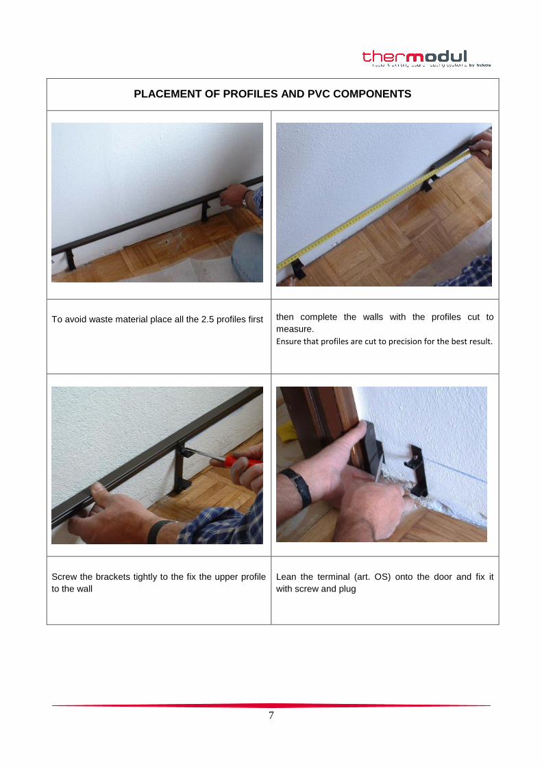
PLACEMENT OF PROFILES AND PVC COMPONENTS
To avoid waste material place all the 2.5 profiles first
then complete the walls with the profiles cut to
measure.
Ensure that profiles are cut to precision for the best result.
Screw the brackets tightly to the fix the upper profile
to the wall
Lean the terminal (art. OS) onto the door and fix it
with screw and plug
8
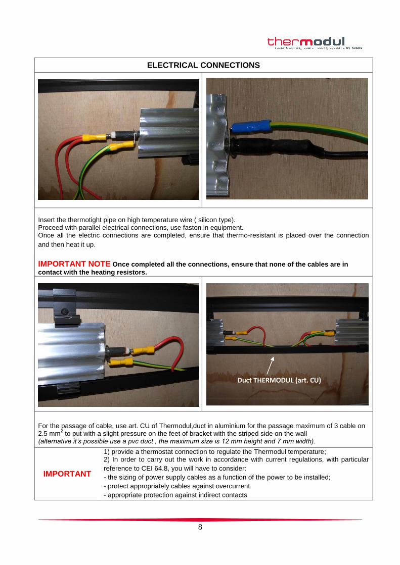
ELECTRICAL CONNECTIONS
Insert the thermotight pipe on high temperature wire ( silicon type). Proceed with parallel electrical connections, use faston in equipment. Once all the electric connections are completed, ensure that thermo-resistant is placed over the connection
and then heat it up.
IMPORTANT NOTE Once completed all the connections, ensure that none of the cables are in
contact with the heating resistors.
Duct THERMODUL (art. CU)
For the passage of cable, use art. CU of Thermodul,duct in aluminium for the passage maximum of 3 cable on 2.5 mm
2 to put with a slight pressure on the feet of bracket with the striped side on the wall
(alternative it’s possible use a pvc duct , the maximum size is 12 mm height and 7 mm width).
IMPORTANT
1) provide a thermostat connection to regulate the Thermodul temperature; 2) In order to carry out the work in accordance with current regulations, with particular
reference to CEI 64.8, you will have to consider:
- the sizing of power supply cables as a function of the power to be installed;
- protect appropriately cables against overcurrent
- appropriate protection against indirect contacts
9
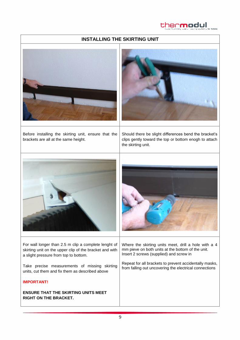
INSTALLING THE SKIRTING UNIT
Before installing the skirting unit, ensure that the
brackets are all at the same height.
Should there be slight differences bend the bracket’s
clips gently toward the top or bottom enogh to attach
the skirting unit.
For wall longer than 2.5 m clip a complete lenght of
skirting unit on the upper clip of the bracket and with
a slight pressure from top to bottom.
Take precise measurements of missing skirting
units, cut them and fix them as described above
IMPORTANT!
ENSURE THAT THE SKIRTING UNITS MEET
RIGHT ON THE BRACKET.
Where the skirting units meet, drill a hole with a 4 mm pieve on both units at the bottom of the unit. Insert 2 screws (supplied) and screw in Repeat for all brackets to prevent accidentally masks, from falling out uncovering the electrical connections
10
Note:
The observance of these installation instructions and respect for all, however small,
expedient, future will avoid wasting time and ensure customer satisfaction with your work
and our product.
THANK YOU
Hekos srl
For help during installation, please contact:
(Hekos customer care service)
Tel 0437.999647 - Fax 0437.999849