Embed Size (px)
Citation preview
Installation S19-210HFPPedestal-Mounted Eyewashin 18”, 3’, 4’, 5’ and 6’ Bury Depths
Table of ContentsPre-Installation Information . . . . . . . . . . . . . . . . . . . . . . 2
Installation . . . . . . . . . . . . . . . . . . . . . . . . . . . . . . . . . . . 3
Assembly of Components . . . . . . . . . . . . . . . . . . . . . 4–5
Parts List . . . . . . . . . . . . . . . . . . . . . . . . . . . . . . . . . . . . 6
actoolsupply.com
actoolsupply.com
actoolsupply.com
Bradley S19-210HFP3 Emergency Eyewash Station Frost ProofBradley S19-210HFP18 Emergency Eyewash Station Frost ProofBradley S19-210HFP4 Emergency Eyewash Station Frost ProofBradley S19-210HFP5 Emergency Eyewash Station Frost ProofBradley S19-210HFP6 Emergency Eyewash Station Frost Proof
2
S19-210HFP Installation
8/12/09
WARNINGRead this installation manual completely to ensure proper installation, then file it with the owner or maintenance department. Compliance and conformity to drain requirements and other local codes and ordinances is the responsibility of the installer.
Separate parts from packaging and make sure all parts are accounted for before discarding any packaging material. If any parts are missing, do not begin installation until you obtain the missing parts.
Flush the water supply lines before beginning installation and after installation is complete. Test the unit for leaks and adequate water flow. Main water supply to the eyewash should be “ON” at all times. Provisions shall be made to prevent unauthorized shutoff.
The ANSI Z358.1 standard requires an uninterruptible supply of flushing fluid at a minimum 30 PSI (0.21 MPa) flowing pressure. Flushing fluid should be tepid per ANSI Z358.1.
The inspection and testing results of this equipment should be recorded weekly to verify proper operation. This equipment should be inspected annually to ensure compliance with ANSI Z358.1.
Workers who may come in contact with potentially hazardous materials should be trained regarding the placement and proper operation of emergency equipment per ANSI Z358.1.
Installation
THIS
SIDE
UP
Packing List
••••
P.O. B
ox 3
09, M
enom
onee F
alls
, WI 5
3051
R
TEST THIS
UNIT
EACH W
EEK
Test
-oper
ate
valv
e(s)
eac
h wee
k an
d sig
n bel
ow.
Report
any
mal
funct
ions
imm
edia
tely.
Ventil
(e) w
öchen
tlich
im Te
stbet
rieb
prüfe
n, bes
tätig
t
durch U
nters
chrif
t. Je
gliche
Störu
ng s
ofort
mel
den.
Date
Datum
Date
Signed
Unters
chrif
t
Signe
Date
DateDat
e
Signed
Signed
Signed
DIESES G
ERÄT 1ST W
ÖCHENTLIC
H ZU P
RÜFEN.
ESSAI HEBDO
MADAIR
E
Test
le fo
nctio
nnemen
t des
val
ves
chaq
ue se
mai
ne et
signe
en b
as. S
'il y
à q
uelque
chose
qui n
e va
pas
fait
un rapport
imm
édia
tem
ent.
P.O. BOX 309, MENOMONEE FALLS, WI 53052-0309 USATEL: 1-800-BRADLEY FAX: (262-251-5817)
http://www.bradleycorp.com
114-051
Supplies Required:• (3) 3⁄8" floor anchors and bolts
• Pipe sealant
• Material for concrete footings
• Crushed stone
• Piping to 1¼" NPT water supply inlet on unit
• Piping to 1¼" NPT drain outlet for eye wash on unit
actoolsupply.com
actoolsupply.com
3
Installation S19-210HFP
8/12/09
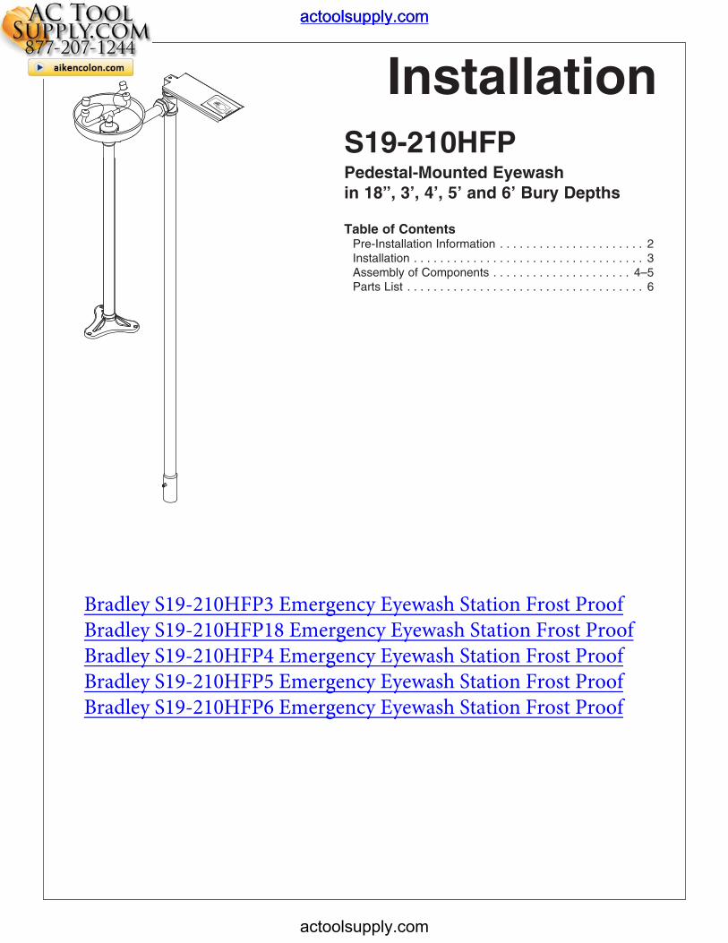
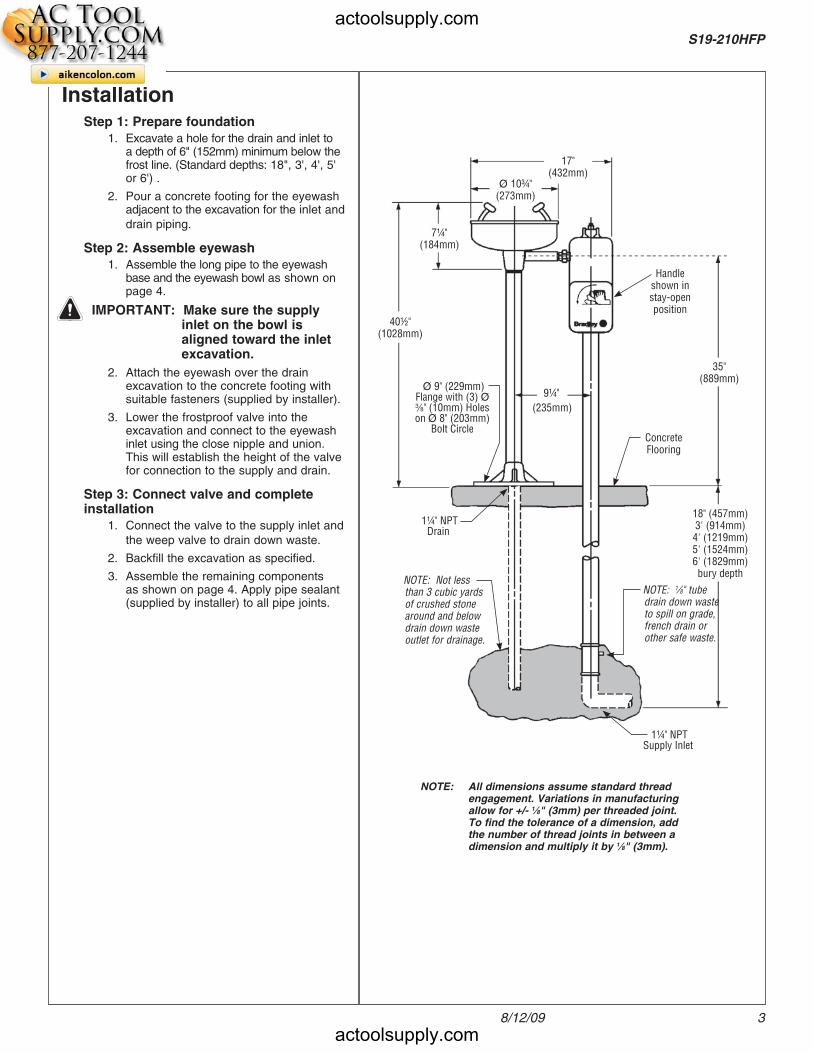
17"(432mm)
Ø 10¾"(273mm)
7¼"(184mm)
40½"(1028mm)
9¼"
(235mm)
35"(889mm)
Handle shown in stay-open position
NOTE: All dimensions assume standard thread engagement. Variations in manufacturing allow for +/- 1⁄8" (3mm) per threaded joint. To find the tolerance of a dimension, add the number of thread joints in between a dimension and multiply it by 1⁄8" (3mm).
InstallationStep 1: Prepare foundation
1. Excavate a hole for the drain and inlet toa depth of 6" (152mm) minimum below thefrost line. (Standard depths: 18", 3', 4', 5'or 6') .
2. Pour a concrete footing for the eyewashadjacent to the excavation for the inlet and
drain piping.
Step 2: Assemble eyewash1. Assemble the long pipe to the eyewash
base and the eyewash bowl as shown onpage 4.
IMPORTANT: Make sure the supply inlet on the bowl is aligned toward the inlet excavation.
2. Attach the eyewash over the drainexcavation to the concrete footing withsuitable fasteners (supplied by installer).
3. Lower the frostproof valve into theexcavation and connect to the eyewashinlet using the close nipple and union.This will establish the height of the valvefor connection to the supply and drain.
Step 3: Connect valve and complete installation
1. Connect the valve to the supply inlet and
the weep valve to drain down waste.
2. Backfill the excavation as specified.
3. Assemble the remaining componentsas shown on page 4. Apply pipe sealant(supplied by installer) to all pipe joints.
Concrete Flooring
18" (457mm)3' (914mm)4' (1219mm)5' (1524mm)6' (1829mm)bury depth
Ø 9" (229mm) Flange with (3) Ø 3⁄8" (10mm) Holes on Ø 8" (203mm)
Bolt Circle
NOTE: 1⁄8" tube drain down waste to spill on grade, french drain or other safe waste.
NOTE: Not less than 3 cubic yards of crushed stone around and below drain down waste outlet for drainage.
1¼" NPT Supply Inlet
1¼" NPT Drain
actoolsupply.com
actoolsupply.com
4
S19-210HFP Installation
8/12/09
P.O. Box 309, Menomonee Falls, WI 53051
R
TEST THIS UNIT EACH WEEK
Test-operate valve(s) each week and sign below.Report any malfunctions immediately.
Ventil(e) wöchentlich im Testbetrieb prüfen, bestätigtdurch Unterschrift. Jegliche Störung sofort melden.
DateDatumDate
SignedUnterschriftSigne
DateDate
Date SignedSignedSigned
DIESES GERÄT 1ST WÖCHENTLICH ZU PRÜFEN.ESSAI HEBDOMADAIRE
Test le fonctionnement des valves chaque semaine et signe en bas. S'il y à quelque chose qui ne va pas faitun rapport immédiatement.
P.O. BOX 309, MENOMONEE FALLS, WI 53052-0309 USATEL: 1-800-BRADLEY FAX: (262-251-5817)
http://www.bradleycorp.com
114-051
8
7
5
34
9
10
1
2
6
6.1
6.2
6.3
6.4
6.5
6.6
6.7
6.8
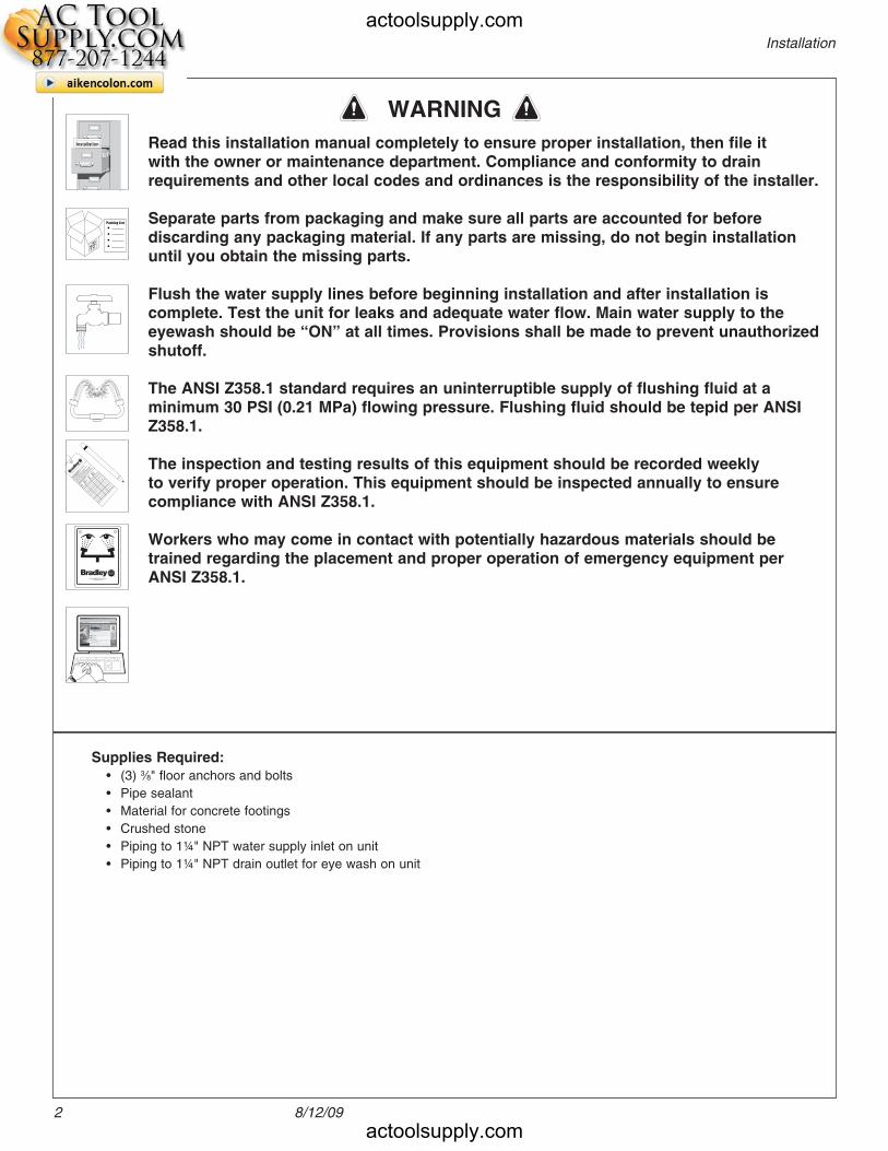
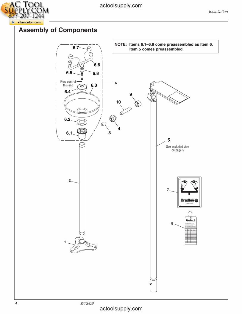
Assembly of Components
NOTE: Items 6.1–6.8 come preassembled as Item 6. Item 5 comes preassembled.
See exploded view on page 5
Flow control this end
actoolsupply.com
actoolsupply.com
5
Installation S19-210HFP
8/12/09
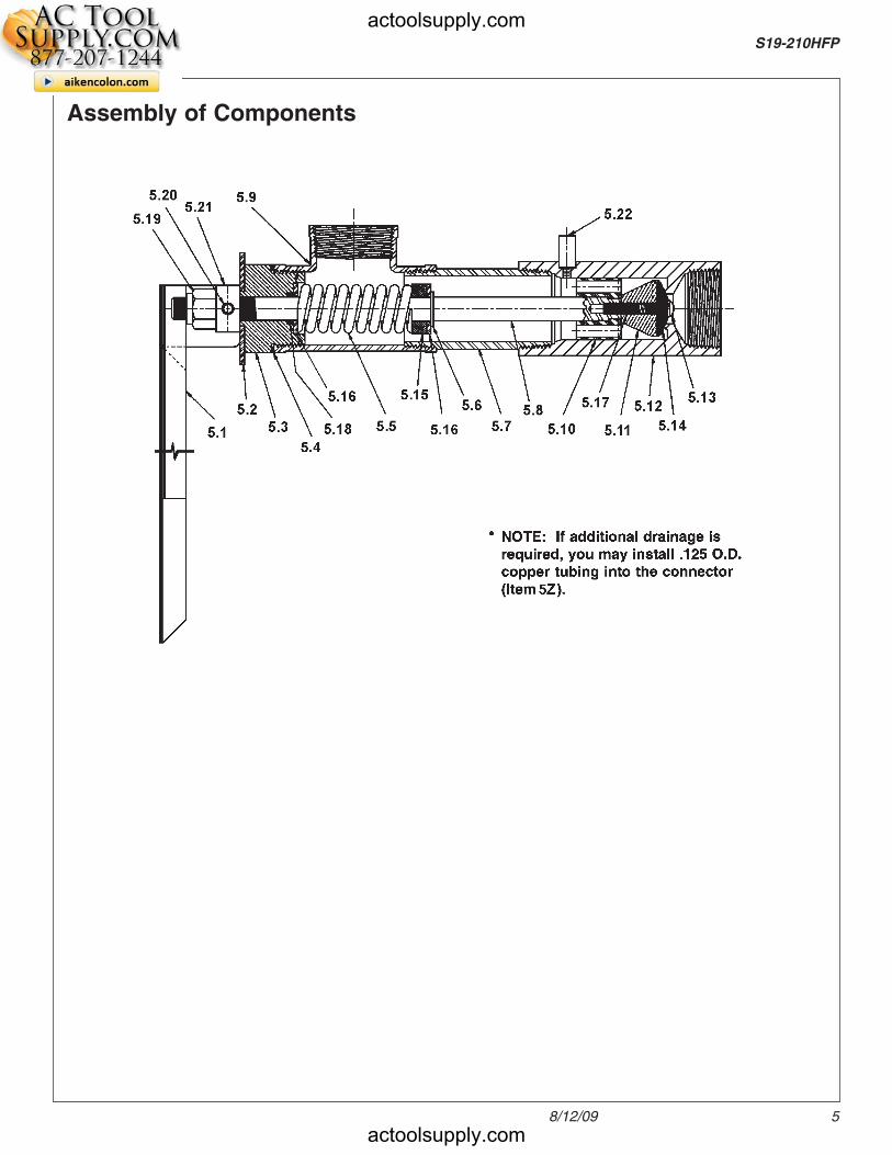
Assembly of Components
actoolsupply.com
actoolsupply.com
6
S19-210HFP Installation
8/12/09
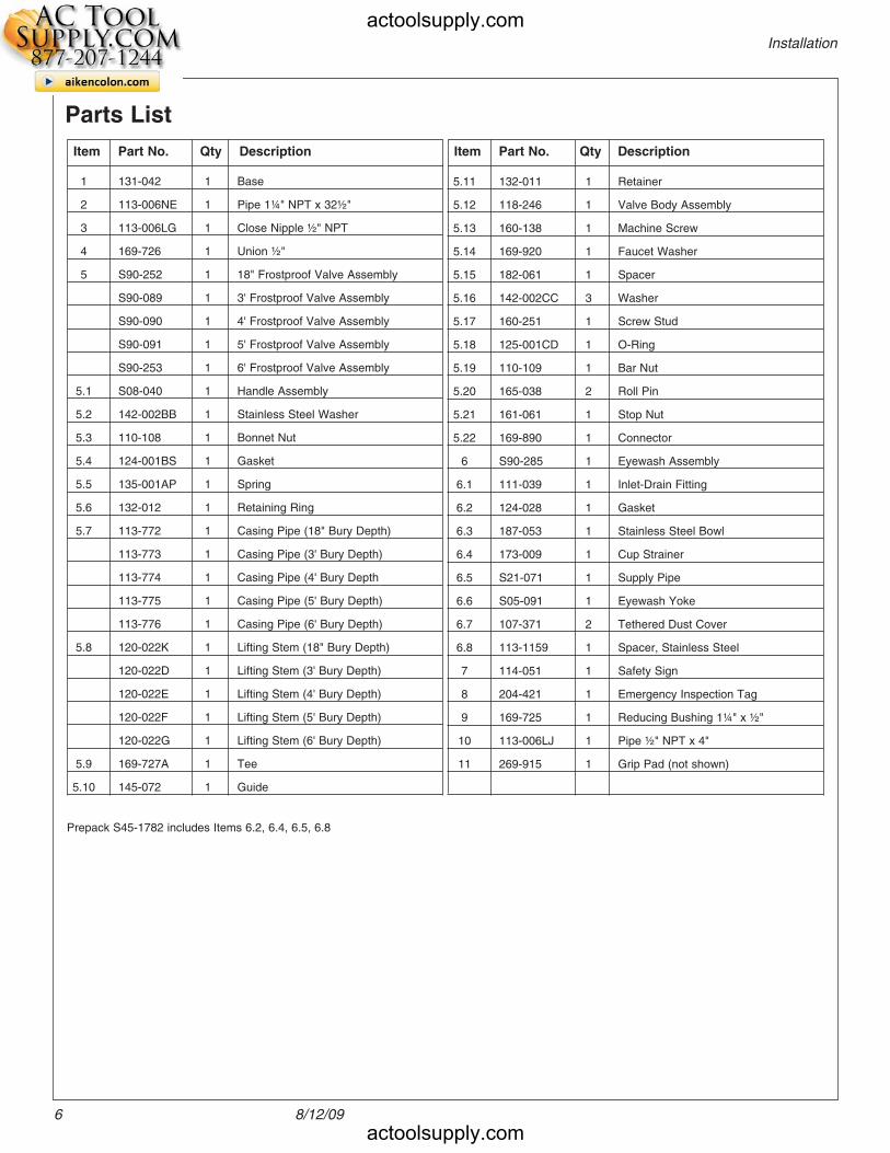
Parts List
1 131-042 1 Base
2 113-006NE 1 Pipe 1¼" NPT x 32½"
3 113-006LG 1 Close Nipple ½" NPT
4 169-726 1 Union ½"
5 S90-252 1 18" Frostproof Valve Assembly
S90-089 1 3' Frostproof Valve Assembly
S90-090 1 4' Frostproof Valve Assembly
S90-091 1 5' Frostproof Valve Assembly
S90-253 1 6' Frostproof Valve Assembly
5.1 S08-040 1 Handle Assembly
5.2 142-002BB 1 Stainless Steel Washer
5.3 110-108 1 Bonnet Nut
5.4 124-001BS 1 Gasket
5.5 135-001AP 1 Spring
5.6 132-012 1 Retaining Ring
5.7 113-772 1 Casing Pipe (18" Bury Depth)
113-773 1 Casing Pipe (3' Bury Depth)
113-774 1 Casing Pipe (4' Bury Depth
113-775 1 Casing Pipe (5' Bury Depth)
113-776 1 Casing Pipe (6' Bury Depth)
5.8 120-022K 1 Lifting Stem (18" Bury Depth)
120-022D 1 Lifting Stem (3' Bury Depth)
120-022E 1 Lifting Stem (4' Bury Depth)
120-022F 1 Lifting Stem (5' Bury Depth)
120-022G 1 Lifting Stem (6' Bury Depth)
5.9 169-727A 1 Tee
5.10 145-072 1 Guide
5.11 132-011 1 Retainer
5.12 118-246 1 Valve Body Assembly
5.13 160-138 1 Machine Screw
5.14 169-920 1 Faucet Washer
5.15 182-061 1 Spacer
5.16 142-002CC 3 Washer
5.17 160-251 1 Screw Stud
5.18 125-001CD 1 O-Ring
5.19 110-109 1 Bar Nut
5.20 165-038 2 Roll Pin
5.21 161-061 1 Stop Nut
5.22 169-890 1 Connector
6 S90-285 1 Eyewash Assembly
6.1 111-039 1 Inlet-Drain Fitting
6.2 124-028 1 Gasket
6.3 187-053 1 Stainless Steel Bowl
6.4 173-009 1 Cup Strainer
6.5 S21-071 1 Supply Pipe
6.6 S05-091 1 Eyewash Yoke
6.7 107-371 2 Tethered Dust Cover
6.8 113-1159 1 Spacer, Stainless Steel
7 114-051 1 Safety Sign
8 204-421 1 Emergency Inspection Tag
9 169-725 1 Reducing Bushing 1¼" x ½"
10 113-006LJ 1 Pipe ½" NPT x 4"
11 269-915 1 Grip Pad (not shown)
Item Part No. Qty Description Item Part No. Qty Description
Prepack S45-1782 includes Items 6.2, 6.4, 6.5, 6.8
actoolsupply.com
actoolsupply.com