Embed Size (px)
Citation preview
System Storage EXP3000
Installation, User’s, and Maintenance Guide
���


System Storage EXP3000
Installation, User’s, and Maintenance Guide
���
Note: Before using this information and the product it supports, read the general information in Appendix B, “Notices,” on page 41.
Third Edition (December 2007)
© Copyright International Business Machines Corporation 2007. All rights reserved.
US Government Users Restricted Rights – Use, duplication or disclosure restricted by GSA ADP Schedule Contract
with IBM Corp.
Safety
Before installing this product, read the Safety Information.
Antes de instalar este produto, leia as Informações de Segurança.
Pred instalací tohoto produktu si prectete prírucku bezpecnostních instrukcí.
Læs sikkerhedsforskrifterne, før du installerer dette produkt.
Lees voordat u dit product installeert eerst de veiligheidsvoorschriften.
Ennen kuin asennat tämän tuotteen, lue turvaohjeet kohdasta Safety Information.
Avant d’installer ce produit, lisez les consignes de sécurité.
Vor der Installation dieses Produkts die Sicherheitshinweise lesen.
Prima di installare questo prodotto, leggere le Informazioni sulla Sicurezza.
Les sikkerhetsinformasjonen (Safety Information) før du installerer dette produktet.
Antes de instalar este produto, leia as Informações sobre Segurança.
Antes de instalar este producto, lea la información de seguridad.
Läs säkerhetsinformationen innan du installerar den här produkten.
© Copyright IBM Corp. 2007 iii
Important:
Each caution and danger statement in this document is labeled with a number. This
number is used to cross reference the English-language caution or danger
statement with translated versions of the caution or danger statement in the IBM
Systems Safety Notices document.
For example, if a caution statement is labeled “D005a,” translations for that caution
statement are in the IBM Systems Safety Notices document under “D005a.”
Be sure to read all caution and danger statements in this document before you
perform the procedures. Read any additional safety information that comes with the
server or optional device before you install the device.
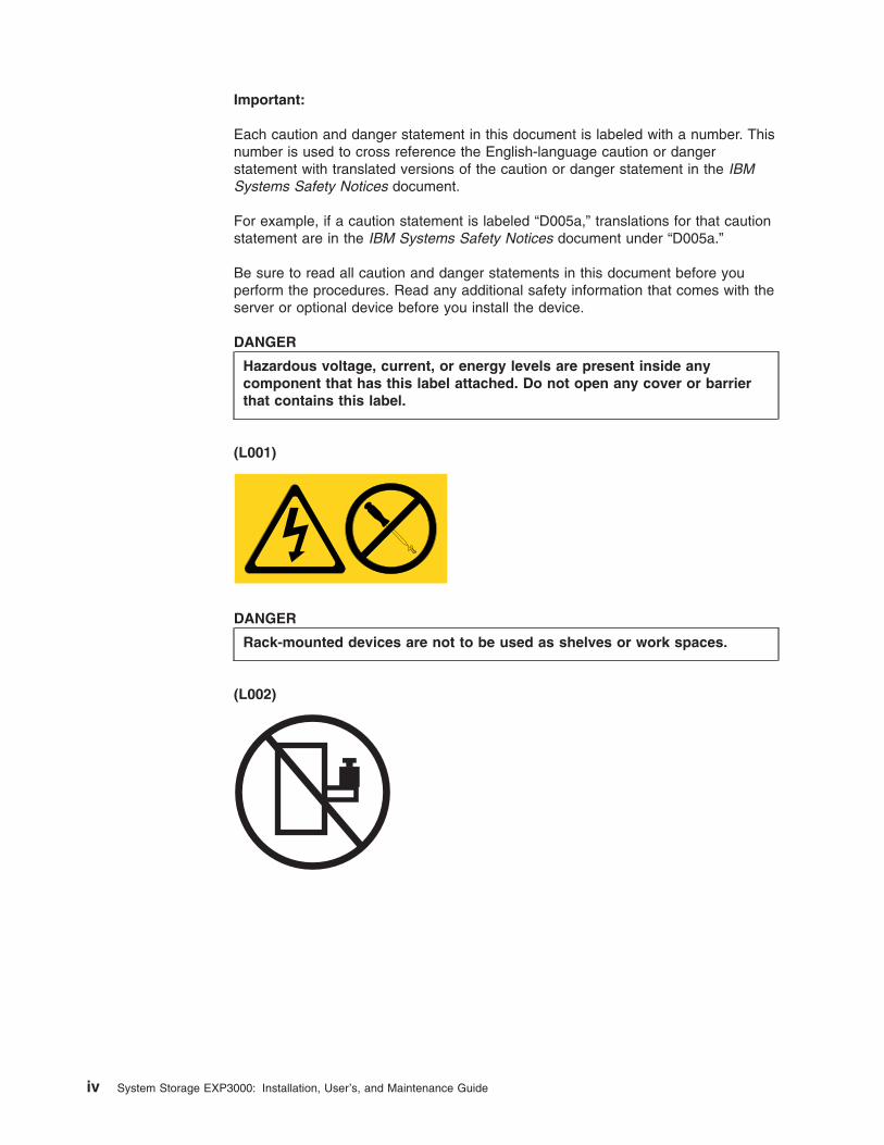
DANGER
Hazardous voltage, current, or energy levels are present inside any
component that has this label attached. Do not open any cover or barrier
that contains this label.
(L001)
DANGER
Rack-mounted devices are not to be used as shelves or work spaces.
(L002)
iv System Storage EXP3000: Installation, User’s, and Maintenance Guide
DANGER
Multiple power cords. The product might be equipped with multiple power
cords. To remove all hazardous voltages, disconect all power cords.
(L003)
1 2
or
!
1
2
Safety v
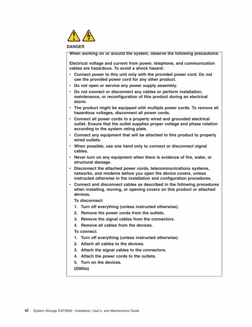
DANGER
When working on or around the system, observe the following precautions:
Electrical voltage and current from power, telephone, and communication
cables are hazardous. To avoid a shock hazard:
v Connect power to this unit only with the provided power cord. Do not
use the provided power cord for any other product.
v Do not open or service any power supply assembly.
v Do not connect or disconnect any cables or perform installation,
maintenance, or reconfiguration of this product during an electrical
storm.
v The product might be equipped with multiple power cords. To remove all
hazardous voltages, disconnect all power cords.
v Connect all power cords to a properly wired and grounded electrical
outlet. Ensure that the outlet supplies proper voltage and phase rotation
according to the system rating plate.
v Connect any equipment that will be attached to this product to properly
wired outlets.
v When possible, use one hand only to connect or disconnect signal
cables.
v Never turn on any equipment when there is evidence of fire, water, or
structural damage.
v Disconnect the attached power cords, telecommunications systems,
networks, and modems before you open the device covers, unless
instructed otherwise in the installation and configuration procedures.
v Connect and disconnect cables as described in the following procedures
when installing, moving, or opening covers on this product or attached
devices.
To disconnect:
1. Turn off everything (unless instructed otherwise).
2. Remove the power cords from the outlets.
3. Remove the signal cables from the connectors.
4. Remove all cables from the devices.
To connect:
1. Turn off everything (unless instructed otherwise).
2. Attach all cables to the devices.
3. Attach the signal cables to the connectors.
4. Attach the power cords to the outlets.
5. Turn on the devices.
(D005a)
vi System Storage EXP3000: Installation, User’s, and Maintenance Guide
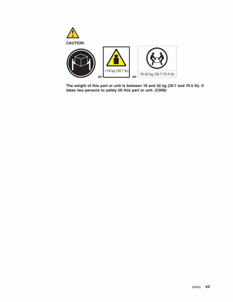
CAUTION:
or
>18 kg (39.7 lb)
or
18-32 kg (39.7-70.5 lb)
The weight of this part or unit is between 18 and 32 kg (39.7 and 70.5 lb). It
takes two persons to safely lift this part or unit. (C009)
Safety vii

viii System Storage EXP3000: Installation, User’s, and Maintenance Guide
Contents
Safety . . . . . . . . . . . . . . . . . . . . . . . . . . . . iii
Chapter 1. Introduction . . . . . . . . . . . . . . . . . . . . . . 1
The IBM Documentation CD . . . . . . . . . . . . . . . . . . . . 3
Hardware and software requirements . . . . . . . . . . . . . . . . 3
Using the Documentation Browser . . . . . . . . . . . . . . . . . 3
Notices and statements in this document . . . . . . . . . . . . . . . . 4
Features and operating specifications . . . . . . . . . . . . . . . . . 5
What the IBM System Storage EXP3000 offers . . . . . . . . . . . . . 5
Major components of the EXP3000 . . . . . . . . . . . . . . . . . . 6
Chapter 2. Installation . . . . . . . . . . . . . . . . . . . . . . 9
Inventory checklist . . . . . . . . . . . . . . . . . . . . . . . . 9
Installing the EXP3000 in a rack . . . . . . . . . . . . . . . . . . . 9
Installing hot-swap hard disk drives . . . . . . . . . . . . . . . . . . 9
Installing an additional ESM . . . . . . . . . . . . . . . . . . . . 11
Installing identification labels . . . . . . . . . . . . . . . . . . . . 11
Cabling the EXP3000 . . . . . . . . . . . . . . . . . . . . . . 12
Single-ESM configuration . . . . . . . . . . . . . . . . . . . . 12
Dual-ESM configuration . . . . . . . . . . . . . . . . . . . . . 13
Connecting the power cords . . . . . . . . . . . . . . . . . . . . 15
Systems-management software support . . . . . . . . . . . . . . . . 15
Chapter 3. EXP3000 controls, LEDs, and power . . . . . . . . . . . . 17
Front view: components . . . . . . . . . . . . . . . . . . . . . 17
Front view: LEDs . . . . . . . . . . . . . . . . . . . . . . . . 18
Rear view: power supply . . . . . . . . . . . . . . . . . . . . . 19
Rear view: ESMs . . . . . . . . . . . . . . . . . . . . . . . . 20
EXP3000 power features . . . . . . . . . . . . . . . . . . . . . 21
Turning on the EXP3000 . . . . . . . . . . . . . . . . . . . . 21
Turning off the EXP3000 . . . . . . . . . . . . . . . . . . . . 22
Turning off the EXP3000 in an emergency . . . . . . . . . . . . . . 23
Turning on the EXP3000 after an emergency . . . . . . . . . . . . . 23
Chapter 4. Replacing components . . . . . . . . . . . . . . . . . 25
Replaceable EXP3000 components . . . . . . . . . . . . . . . . . 25
Installation guidelines . . . . . . . . . . . . . . . . . . . . . . 26
System reliability guidelines . . . . . . . . . . . . . . . . . . . 26
Handling static-sensitive devices . . . . . . . . . . . . . . . . . 27
Working with hot-swap hard disk drives . . . . . . . . . . . . . . . . 27
Replacing a hot-swap hard disk drive . . . . . . . . . . . . . . . . 28
Replacing an ESM . . . . . . . . . . . . . . . . . . . . . . . 29
Replacing a hot-swap power supply . . . . . . . . . . . . . . . . . 30
Replacing the bezels . . . . . . . . . . . . . . . . . . . . . . . 31
Removing the bezels . . . . . . . . . . . . . . . . . . . . . . 32
Installing the bezels . . . . . . . . . . . . . . . . . . . . . . 32
Replacing the release tab on an ESM or power supply . . . . . . . . . . 32
Replacing a drive compatibility key . . . . . . . . . . . . . . . . . 33
Chapter 5. Solving problems . . . . . . . . . . . . . . . . . . . 37
Appendix A. Getting help and technical assistance . . . . . . . . . . 39
Before you call . . . . . . . . . . . . . . . . . . . . . . . . . 39
© Copyright IBM Corp. 2007 ix
Using the documentation . . . . . . . . . . . . . . . . . . . . . 39
Getting help and information from the World Wide Web . . . . . . . . . . 39
Software service and support . . . . . . . . . . . . . . . . . . . 40
Hardware service and support . . . . . . . . . . . . . . . . . . . 40
IBM Taiwan product service . . . . . . . . . . . . . . . . . . . . 40
Appendix B. Notices . . . . . . . . . . . . . . . . . . . . . . 41
Trademarks . . . . . . . . . . . . . . . . . . . . . . . . . . 41
Important notes . . . . . . . . . . . . . . . . . . . . . . . . . 42
Product recycling and disposal . . . . . . . . . . . . . . . . . . . 43
Battery return program . . . . . . . . . . . . . . . . . . . . . . 44
Electronic emission notices . . . . . . . . . . . . . . . . . . . . 46
Federal Communications Commission (FCC) statement . . . . . . . . . 46
Industry Canada Class A emission compliance statement . . . . . . . . 46
Avis de conformité à la réglementation d’Industrie Canada . . . . . . . . 46
Australia and New Zealand Class A statement . . . . . . . . . . . . 46
United Kingdom telecommunications safety requirement . . . . . . . . . 46
European Union EMC Directive conformance statement . . . . . . . . . 46
Taiwanese Class A warning statement . . . . . . . . . . . . . . . 47
Chinese Class A warning statement . . . . . . . . . . . . . . . . 47
Japanese Voluntary Control Council for Interference (VCCI) statement . . . 47
Korean Class A warning statement . . . . . . . . . . . . . . . . 48
Index . . . . . . . . . . . . . . . . . . . . . . . . . . . . 49
x System Storage EXP3000: Installation, User’s, and Maintenance Guide
Chapter 1. Introduction
This Installation, User’s, and Maintenance Guide contains instructions for setting up
your IBM® System Storage™ EXP3000 and instructions for replacing components.
The IBM System Storage EXP3000 is referred to in this document as the EXP3000.
This document contains information about:
v Setting up and cabling the EXP3000
v Starting and configuring the EXP3000
v Replacing components
v Solving problems
The EXP3000 provides high-capacity, Serial Attached SCSI (SAS) or Serial ATA
(SATA) disk storage. It supports up to 12 SAS or SATA hard disk drives. It delivers
fast, high-volume data transfer, retrieval, and storage functions among multiple
drives. The EXP3000 is designed for continuous, reliable service; the modular,
redundant hard disk drives and power supplies (with fans) use hot-swap technology
for easy replacement without turning off the EXP3000.
See http://www.ibm.com/servers/storage/disk/exp3000/index.html for an
interoperability matrix that lists supported hard disk drives for the RAID controller to
which the EXP3000 is connected.
The EXP3000 comes with two 530-watt ac power supplies, one environmental
services module (ESM), a filler panel to cover the empty ESM bay, and 12 drive
filler panels. The drive filler panels can be replaced with optional hard disk drives.
If firmware and documentation updates are available, you can download them from
the IBM support Web site. The EXP3000 might have features that are not described
in the documentation that comes with the unit, and the documentation might be
updated occasionally to include information about those features, or technical
updates might be available to provide additional information that is not included in
the EXP3000 documentation.
Note: Changes are made periodically to the IBM Web site. Procedures for locating
firmware and documentation might vary slightly from what is described in this
document.
If the EXP3000 is attached to a DS3000 storage subsystem:To check for updates, complete the following steps:
1. Go to http://www.ibm.com/servers/storage/support/.
2. On the “Support for System Storage and TotalStorage® products” page, under
Select your product, in the Product family field, select Disk systems.
3. In the Product field, select EXP3000.
4. Click Go.
5. Make the following selections:
v For firmware updates, click the Download tab.
Important: If you are using SATA disk drives with a DS3000 storage
subsystem, the ESM firmware must be at version 1.86 or later. Check the
RAID controller management software for the firmware version that is
installed on the ESM.
© Copyright IBM Corp. 2007 1
v For documentation updates, click the Install and use tab.
If the EXP3000 is directly attached to an IBM System x server or the EXP3000
is attached to an IBM System x server through an IBM ServeRAID HBA:To check for updates, complete the following steps:
1. Go to http://www.ibm.com/servers/support/.
2. Select System x
3. On the "Support for IBM System x" page, in the Product family field, select
System Storage EXP3000.
4. In the Product field, select EXP3000.
5. In the Type field, select 1727.
6. Click Go.
7. Select IBM HBA EXP3000 update program.
The EXP3000 comes with a limited warranty. For more information about the terms
of your warranty, see the Warranty and Support Information document on the IBM
Documentation CD.
Record information about the EXP3000 in Table 1. You will need this information if
you have to call for service.
Table 1. Product identification record
Product name IBM System Storage EXP3000
Machine type 1727
Serial number
EXP3000 ID number
The serial number is on the label in the vertical recess on the left bezel. The serial
number is also on the left chassis flange and on the rear of the chassis. A label that
includes the machine type, model, and serial number is on the top front right
chassis corner. The following illustration shows the product name and serial number
label on the front of the EXP3000.
Note: The illustrations in this document might differ slightly from your hardware.
System Storage
Serial number labelProduct name
Use Table 2 on page 3 to keep a record of the hard disk drives that are installed in
or attached to the EXP3000. This information can be helpful when you install
additional hard disk drives or if you have to report a hardware problem. Make a
copy of this table before you record information in it, in case you need extra space
to write new values later, or when you update the EXP3000 configuration.
2 System Storage EXP3000: Installation, User’s, and Maintenance Guide
Table 2. Drive location information record
Drive location Drive part and model number Drive serial number
Bay 1
Bay 2
Bay 3
Bay 4
Bay 5
Bay 6
Bay 7
Bay 8
Bay 9
Bay 10
Bay 11
Bay 12
The IBM Documentation CD
The IBM Documentation CD contains documentation for the EXP3000 in Portable
Document Format (PDF) and includes the IBM Documentation Browser to help you
find information quickly.
Hardware and software requirements
The IBM Documentation CD requires the following minimum hardware and
software:
v Microsoft® Windows® XP, Windows 2000, or Red Hat® Linux®
v 100 MHz microprocessor
v 32 MB of RAM
v Adobe Acrobat Reader 3.0 (or later) or xpdf, which comes with Linux operating
systems
Using the Documentation Browser
Use the Documentation Browser to browse the contents of the CD, read brief
descriptions of the documents, and view documents, using Adobe Acrobat Reader
or xpdf. The Documentation Browser automatically detects the regional settings in
use in your server and displays the documents in the language for that region (if
available). If a document is not available in the language for that region, the
English-language version is displayed.
Use one of the following procedures to start the Documentation Browser:
v If Autostart is enabled, insert the CD into the CD drive. The Documentation
Browser starts automatically.
v If Autostart is disabled or is not enabled for all users, use one of the following
procedures:
– If you are using a Windows operating system, insert the CD into the CD drive
and click Start --> Run. In the Open field, type
e:\win32.bat
where e is the drive letter of the CD drive, and click OK.
Chapter 1. Introduction 3
– If you are using Red Hat Linux, insert the CD into the CD drive; then, run the
following command from the /mnt/cdrom directory:
sh runlinux.sh
Select the EXP3000 from the Product menu. The Available Topics list displays all
the documents for the EXP3000. Some documents might be in folders. A plus sign
(+) indicates each folder or document that has additional documents under it. Click
the plus sign to display the additional documents.
When you select a document, a description of the document is displayed under
Topic Description. To select more than one document, press and hold the Ctrl key
while you select the documents. Click View Book to view the selected document or
documents in Acrobat Reader or xpdf. If you selected more than one document, all
the selected documents are opened in Acrobat Reader or xpdf.
To search all the documents, type a word or word string in the Search field and
click Search. The documents in which the word or word string appears are listed in
order of the most occurrences. Click a document to view it, and press Crtl+F to use
the Acrobat search function or Alt+F to use the xpdf search function within the
document.
Click Help for detailed information about using the Documentation Browser.
Notices and statements in this document
The caution and danger statements in this document are also in the multilingual
IBM Systems Safety Notices document, which is on the IBM Documentation CD.
Each statement is followed by a reference number that you can use to locate the
corresponding statement in your language in the IBM Systems Safety Notices
document.
The following notices and statements are used in this document:
v Note: These notices provide important tips, guidance, or advice.
v Important: These notices provide information or advice that might help you avoid
inconvenient or problem situations.
v Attention: These notices indicate potential damage to programs, devices, or
data. An attention notice is placed just before the instruction or situation in which
damage might occur.
v Caution: These statements indicate situations that can be potentially hazardous
to you. A caution statement is placed just before the description of a potentially
hazardous procedure step or situation.
v Danger: These statements indicate situations that can be potentially lethal or
extremely hazardous to you. A danger statement is placed just before the
description of a potentially lethal or extremely hazardous procedure step or
situation.
4 System Storage EXP3000: Installation, User’s, and Maintenance Guide
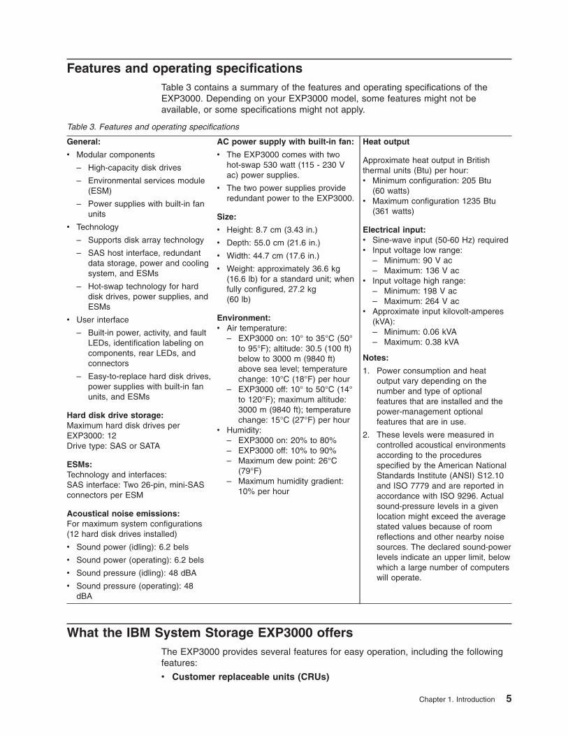
Features and operating specifications
Table 3 contains a summary of the features and operating specifications of the
EXP3000. Depending on your EXP3000 model, some features might not be
available, or some specifications might not apply.
Table 3. Features and operating specifications
General:
v Modular components
– High-capacity disk drives
– Environmental services module
(ESM)
– Power supplies with built-in fan
units
v Technology
– Supports disk array technology
– SAS host interface, redundant
data storage, power and cooling
system, and ESMs
– Hot-swap technology for hard
disk drives, power supplies, and
ESMs
v User interface
– Built-in power, activity, and fault
LEDs, identification labeling on
components, rear LEDs, and
connectors
– Easy-to-replace hard disk drives,
power supplies with built-in fan
units, and ESMs
Hard disk drive storage:
Maximum hard disk drives per
EXP3000: 12
Drive type: SAS or SATA
ESMs:
Technology and interfaces:
SAS interface: Two 26-pin, mini-SAS
connectors per ESM
Acoustical noise emissions:
For maximum system configurations
(12 hard disk drives installed)
v Sound power (idling): 6.2 bels
v Sound power (operating): 6.2 bels
v Sound pressure (idling): 48 dBA
v Sound pressure (operating): 48
dBA
AC power supply with built-in fan:
v The EXP3000 comes with two
hot-swap 530 watt (115 - 230 V
ac) power supplies.
v The two power supplies provide
redundant power to the EXP3000.
Size:
v Height: 8.7 cm (3.43 in.)
v Depth: 55.0 cm (21.6 in.)
v Width: 44.7 cm (17.6 in.)
v Weight: approximately 36.6 kg
(16.6 lb) for a standard unit; when
fully configured, 27.2 kg
(60 lb)
Environment:
v Air temperature:
– EXP3000 on: 10° to 35°C (50°
to 95°F); altitude: 30.5 (100 ft)
below to 3000 m (9840 ft)
above sea level; temperature
change: 10°C (18°F) per hour
– EXP3000 off: 10° to 50°C (14°
to 120°F); maximum altitude:
3000 m (9840 ft); temperature
change: 15°C (27°F) per hourv Humidity:
– EXP3000 on: 20% to 80%
– EXP3000 off: 10% to 90%
– Maximum dew point: 26°C
(79°F)
– Maximum humidity gradient:
10% per hour
Heat output
Approximate heat output in British
thermal units (Btu) per hour:
v Minimum configuration: 205 Btu
(60 watts)
v Maximum configuration 1235 Btu
(361 watts)
Electrical input:
v Sine-wave input (50-60 Hz) required
v Input voltage low range:
– Minimum: 90 V ac
– Maximum: 136 V acv Input voltage high range:
– Minimum: 198 V ac
– Maximum: 264 V acv Approximate input kilovolt-amperes
(kVA):
– Minimum: 0.06 kVA
– Maximum: 0.38 kVA
Notes:
1. Power consumption and heat
output vary depending on the
number and type of optional
features that are installed and the
power-management optional
features that are in use.
2. These levels were measured in
controlled acoustical environments
according to the procedures
specified by the American National
Standards Institute (ANSI) S12.10
and ISO 7779 and are reported in
accordance with ISO 9296. Actual
sound-pressure levels in a given
location might exceed the average
stated values because of room
reflections and other nearby noise
sources. The declared sound-power
levels indicate an upper limit, below
which a large number of computers
will operate.
What the IBM System Storage EXP3000 offers
The EXP3000 provides several features for easy operation, including the following
features:
v Customer replaceable units (CRUs)
Chapter 1. Introduction 5
The major CRUs in the EXP3000 are SAS or SATA hard disk drives, ESMs, and
power supplies. See “Replaceable EXP3000 components” on page 25.
v Fault indicators
All CRUs have fault or status light emitting diodes (LEDs) to indicate hardware
failures.
v Redundant cooling and power capabilities
The EXP3000 uses a dual ac input power system. This means that both power
switches must be turned on for redundant operation. The redundant cooling of
the fans enables continued operation if one fan fails. The EXP3000 comes with
two 530-watt hot-swap power supplies, which provide redundant power for all
EXP3000 configurations. If a problem occurs with one of the power supplies, the
other power supply can meet the power requirements.
Major components of the EXP3000
Orange on a component or label indicates that the component can be hot-swapped.
You can install or remove a hot-swap component while the EXP3000 is running. For
information about installing hot-swap components, see Chapter 4, “Replacing
components,” on page 25.
Blue on components and labels indicates touch points, where you can grip a
component, move a latch, and so on.
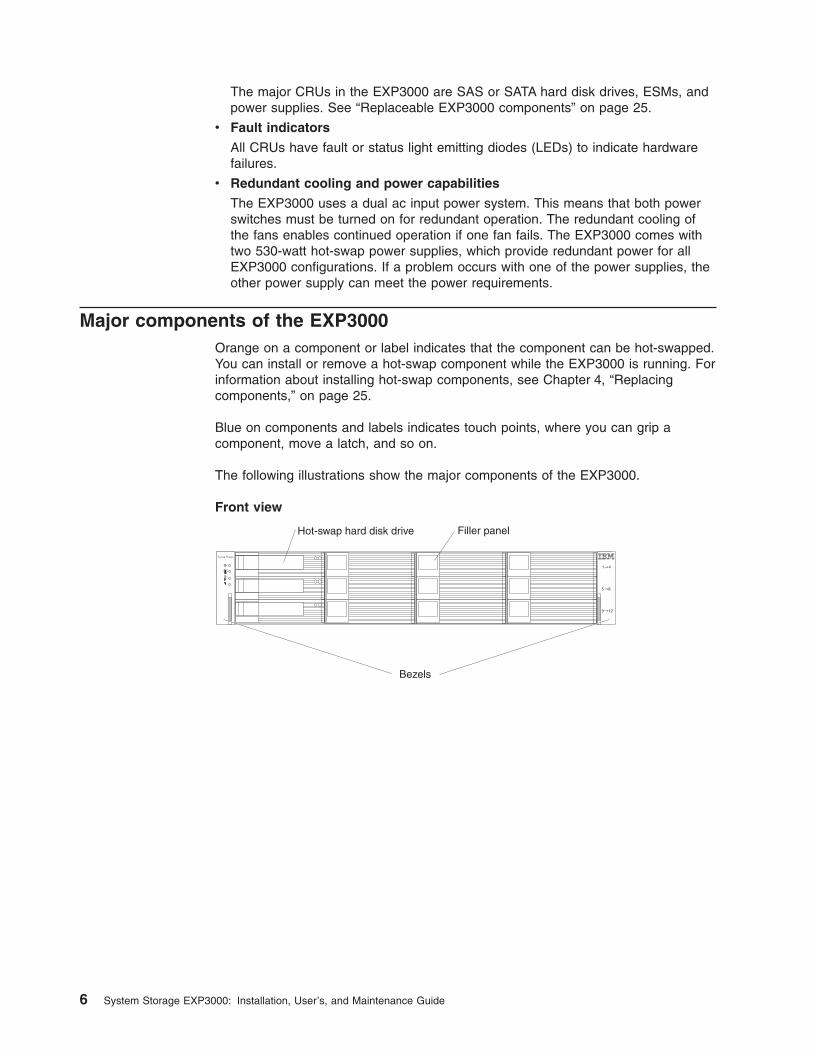
The following illustrations show the major components of the EXP3000.
Front view
Hot-swap hard disk drive Filler panel
System Storage
Bezels
6 System Storage EXP3000: Installation, User’s, and Maintenance Guide
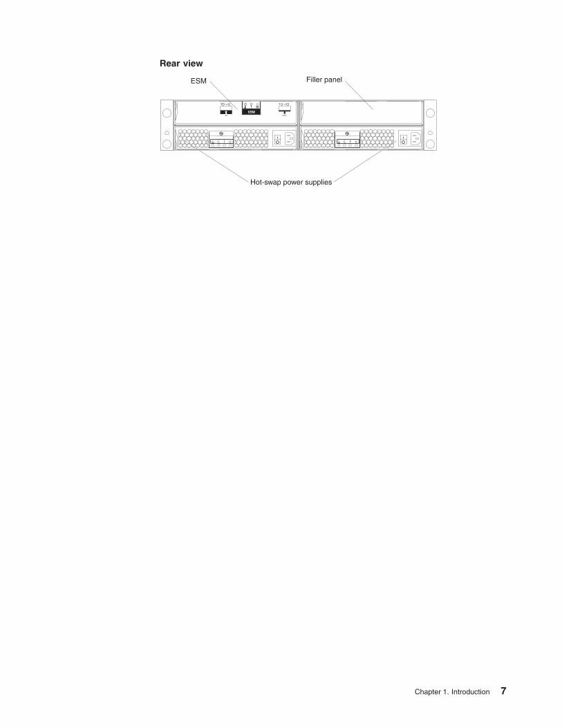
Rear view
Hot-swap power supplies
ESM Filler panel
Chapter 1. Introduction 7

8 System Storage EXP3000: Installation, User’s, and Maintenance Guide
Chapter 2. Installation
This chapter provides information about installing and cabling the EXP3000. The
EXP3000 connects to a RAID controller in a server or in another supported device
such as an IBM System Storage DS3200 or DS3400. See http://www.ibm.com/servers/storage/disk/exp3000/index.html for an interoperability matrix that lists
supported RAID controllers to which the EXP3000 can connect.
Inventory checklist
After you unpack the EXP3000, make sure that you have the following items:
v Hardware:
– IBM System Storage EXP3000
– Two rack jumper power cords
– One sheet of ID labels
– Two front bezels (left and right)
– One rack installation hardware kit:
- Two rails (right and left assembly)
- Eight M5 screws
- Six M5 washers
- Two M4 pan-head screws
- Eight spacers
v Printed documents:
– IBM System Storage EXP3000 Quick Start Guide
– Rack Installation Instructions
v Online documents:
– IBM System Storage EXP3000 Installation and User’s Guide
– IBM Systems Safety Notices
All documents are available on the IBM Documentation CD or from the IBM support
Web site at http://www.ibm.com/servers/storage/support/.
Installing the EXP3000 in a rack
You can install the EXP3000 in an Electronic Industries Association (EIA) 310
standard rack cabinet. For complete rack installation instructions, see the Rack
Installation Instructions document that comes with the EXP3000.
Installing hot-swap hard disk drives
The EXP3000 supports up to 12 IBM SAS or SATA hard disk drives. See
http://www.ibm.com/servers/storage/disk/exp3000/index.html for an interoperability
matrix that lists supported hard disk drives for the RAID controller to which the
EXP3000 can connect.
Each drive comes preinstalled in a drive tray, ready for installation in the EXP3000.
(Do not detach the drive from the tray.) Be sure to record the location information
for each drive in Table 2 on page 3.
© Copyright IBM Corp. 2007 9
The EXP3000 comes with filler panels in the drive bays. Before you install a new
hard disk drive, remove the filler panel and save it for future use. Each of the 12
bays must contain either a filler panel or a hard disk drive.
To install a hard disk drive in the EXP3000, complete the following steps. You can
install drives while the EXP3000 is turned on.
1. Read the instructions that come with the hard disk drive.
2. Read the safety information that begins on page iii and “Installation guidelines”
on page 26.
3. Remove the filler panel from the bay into which you want to install the hard disk
drive:
a. Insert a finger into the square hole on the left side of the filler panel to grip
and pull the filler panel out of the drive bay.
b. Save the filler panel for future use.
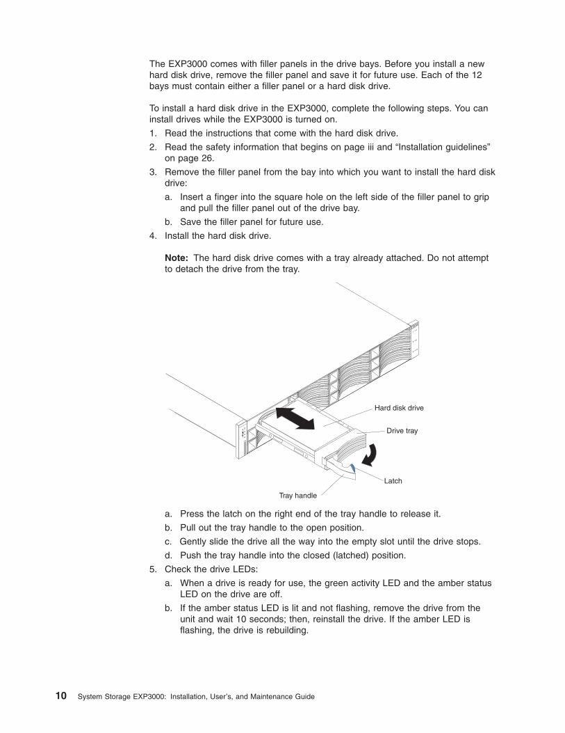
4. Install the hard disk drive.
Note: The hard disk drive comes with a tray already attached. Do not attempt
to detach the drive from the tray.
Drive tray
Tray handle
Latch
Hard disk drive
System
Storage
a. Press the latch on the right end of the tray handle to release it.
b. Pull out the tray handle to the open position.
c. Gently slide the drive all the way into the empty slot until the drive stops.
d. Push the tray handle into the closed (latched) position.
5. Check the drive LEDs:
a. When a drive is ready for use, the green activity LED and the amber status
LED on the drive are off.
b. If the amber status LED is lit and not flashing, remove the drive from the
unit and wait 10 seconds; then, reinstall the drive. If the amber LED is
flashing, the drive is rebuilding.
10 System Storage EXP3000: Installation, User’s, and Maintenance Guide
Controller management information: In some cases, the RAID controller automatically
resets the drive to the Hot Spare or Rebuild state. If the drive state does not change
automatically (the amber LED stays lit), see your RAID controller management
documentation for information about manually changing the state of the drive from the
current state to another state, such as Hot Spare or Ready. The amber LED should turn off
within 10 seconds after the drive state changes.
6. Configure the hard disk drive, using the RAID controller management software.
Installing an additional ESM
The EXP3000 comes with one environmental services module (ESM). If your RAID
controller supports redundant drive paths (see the documentation that comes with
the RAID controller or the device that contains the RAID controller), you can install
a second ESM.
To install a second ESM, complete the following steps:
1. Read the safety information that begins on page iii and “Installation guidelines”
on page 26.
2. Remove the ESM filler panel from the rightmost ESM bay of the EXP3000:
a. On the left side of the ESM filler panel, press the orange release tab to the
right just enough to release the handle (no more than 6 mm [0.25 in.]) as
you rotate the handle upward.
b. Using the handle, gently slide the ESM filler panel out of the EXP3000.
Save the ESM filler panel for future use.
3. Hold the new ESM so that the handle is fully extended.
4. Gently slide the ESM into the bay until it stops. Rotate the handle downward
into the closed position until it clicks.
5. Connect the SAS cable or cables to the ESM. See “Cabling the EXP3000” on
page 12 for more information.
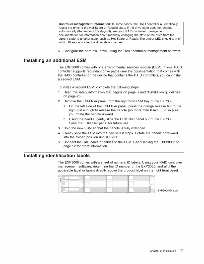
Installing identification labels
The EXP3000 comes with a sheet of numeric ID labels. Using your RAID controller
management software, determine the ID number of the EXP3000, and affix the
applicable label or labels directly above the product label on the right front bezel.
System Storage
EXP3000 ID label
Chapter 2. Installation 11
Cabling the EXP3000
The EXP3000 comes with one ESM, which enables you to connect the EXP3000 to
a RAID controller. Depending on the capabilities of the RAID controller, you can add
a second ESM to the EXP3000 to provide a redundant drive path to the server, and
you can create a chain of EXP3000s to the RAID controller. See the documentation
that comes with the RAID controller or the device that contains the RAID controller
for information about the capabilities of the RAID controller.
Single-ESM configuration
An ESM in the EXP3000 has two 26-pin mini-SAS connectors. The SAS connectors
are labeled In (↑) and Out (↓). If your RAID controller supports more than one
EXP3000 per physical port, you can connect two or more EXP3000s by chaining
them together. See the documentation that comes with your RAID controller or the
device that contains the RAID controller for more information.
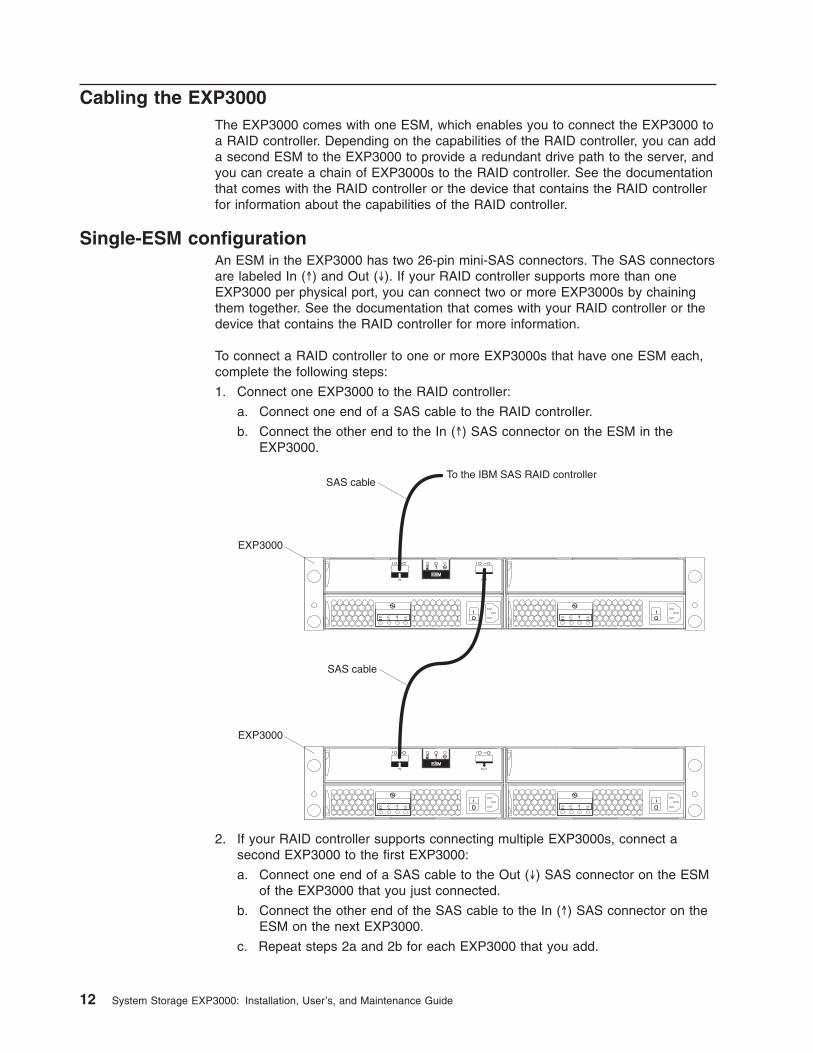
To connect a RAID controller to one or more EXP3000s that have one ESM each,
complete the following steps:
1. Connect one EXP3000 to the RAID controller:
a. Connect one end of a SAS cable to the RAID controller.
b. Connect the other end to the In (↑) SAS connector on the ESM in the
EXP3000.
SAS cable
SAS cable
EXP3000
EXP3000
To the IBM SAS RAID controller
2. If your RAID controller supports connecting multiple EXP3000s, connect a
second EXP3000 to the first EXP3000:
a. Connect one end of a SAS cable to the Out (↓) SAS connector on the ESM
of the EXP3000 that you just connected.
b. Connect the other end of the SAS cable to the In (↑) SAS connector on the
ESM on the next EXP3000.
c. Repeat steps 2a and 2b for each EXP3000 that you add.
12 System Storage EXP3000: Installation, User’s, and Maintenance Guide
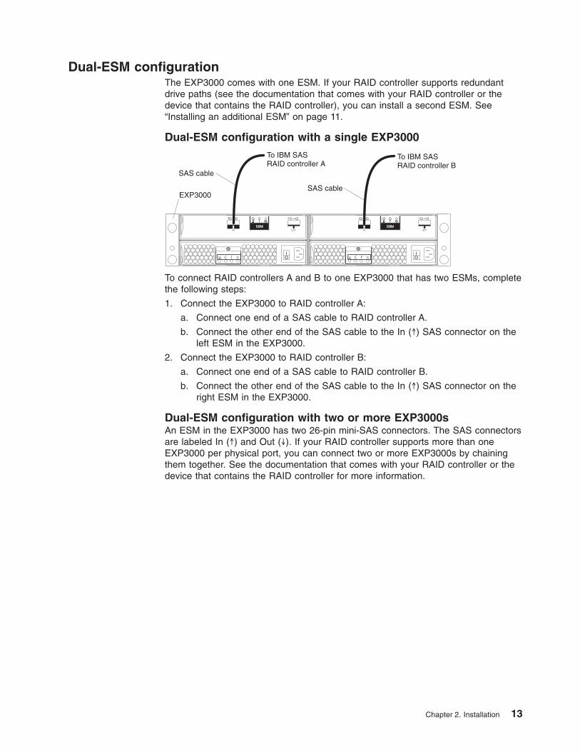
Dual-ESM configuration
The EXP3000 comes with one ESM. If your RAID controller supports redundant
drive paths (see the documentation that comes with your RAID controller or the
device that contains the RAID controller), you can install a second ESM. See
“Installing an additional ESM” on page 11.
Dual-ESM configuration with a single EXP3000
SAS cable
SAS cableEXP3000
To IBM SASRAID controller A
To IBM SASRAID controller B
To connect RAID controllers A and B to one EXP3000 that has two ESMs, complete
the following steps:
1. Connect the EXP3000 to RAID controller A:
a. Connect one end of a SAS cable to RAID controller A.
b. Connect the other end of the SAS cable to the In (↑) SAS connector on the
left ESM in the EXP3000.
2. Connect the EXP3000 to RAID controller B:
a. Connect one end of a SAS cable to RAID controller B.
b. Connect the other end of the SAS cable to the In (↑) SAS connector on the
right ESM in the EXP3000.
Dual-ESM configuration with two or more EXP3000s
An ESM in the EXP3000 has two 26-pin mini-SAS connectors. The SAS connectors
are labeled In (↑) and Out (↓). If your RAID controller supports more than one
EXP3000 per physical port, you can connect two or more EXP3000s by chaining
them together. See the documentation that comes with your RAID controller or the
device that contains the RAID controller for more information.
Chapter 2. Installation 13
SAS cable
SAS cable
SAS cable
SAS cable
EXP3000
EXP3000
To IBM SAS RAID controller A
To IBM SAS RAID controller B
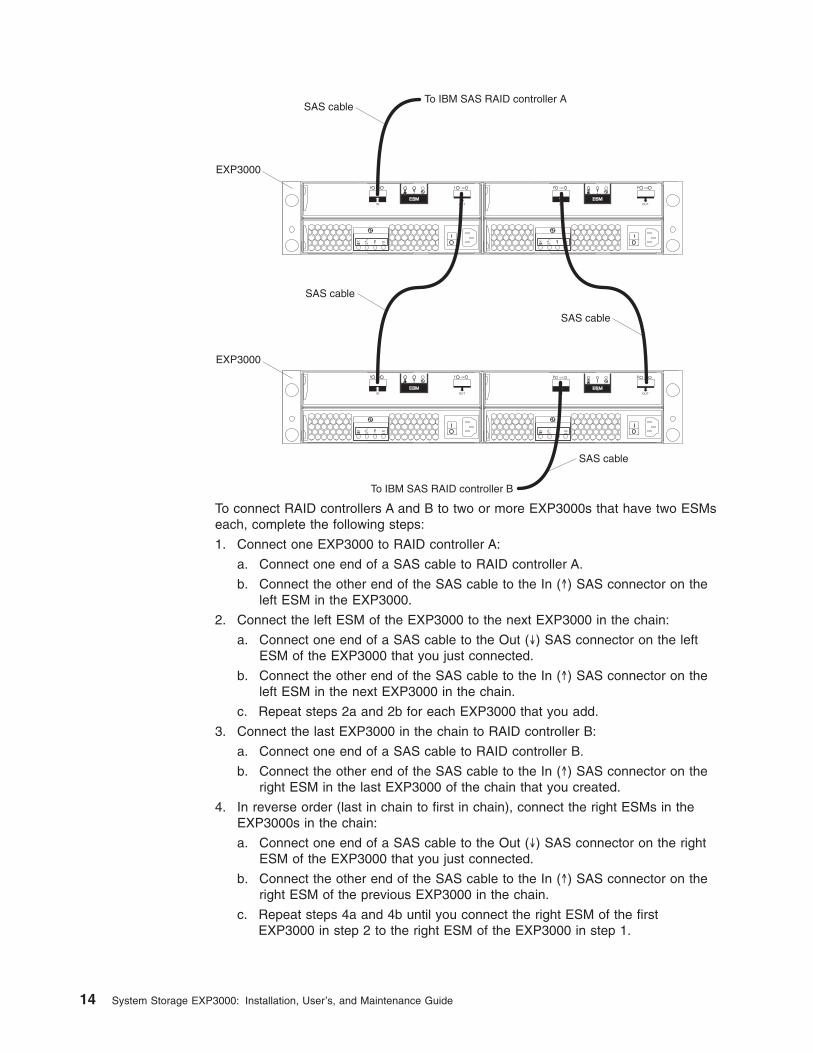
To connect RAID controllers A and B to two or more EXP3000s that have two ESMs
each, complete the following steps:
1. Connect one EXP3000 to RAID controller A:
a. Connect one end of a SAS cable to RAID controller A.
b. Connect the other end of the SAS cable to the In (↑) SAS connector on the
left ESM in the EXP3000.
2. Connect the left ESM of the EXP3000 to the next EXP3000 in the chain:
a. Connect one end of a SAS cable to the Out (↓) SAS connector on the left
ESM of the EXP3000 that you just connected.
b. Connect the other end of the SAS cable to the In (↑) SAS connector on the
left ESM in the next EXP3000 in the chain.
c. Repeat steps 2a and 2b for each EXP3000 that you add.
3. Connect the last EXP3000 in the chain to RAID controller B:
a. Connect one end of a SAS cable to RAID controller B.
b. Connect the other end of the SAS cable to the In (↑) SAS connector on the
right ESM in the last EXP3000 of the chain that you created.
4. In reverse order (last in chain to first in chain), connect the right ESMs in the
EXP3000s in the chain:
a. Connect one end of a SAS cable to the Out (↓) SAS connector on the right
ESM of the EXP3000 that you just connected.
b. Connect the other end of the SAS cable to the In (↑) SAS connector on the
right ESM of the previous EXP3000 in the chain.
c. Repeat steps 4a and 4b until you connect the right ESM of the first
EXP3000 in step 2 to the right ESM of the EXP3000 in step 1.
14 System Storage EXP3000: Installation, User’s, and Maintenance Guide
Connecting the power cords
The EXP3000 comes with two power cords. You can connect the power cords to a
primary power unit inside the rack cabinet, such as a properly grounded ac power
distribution unit (PDU) or uninterruptible power supply.
Note: Power cords, specific to a country, can be purchased separately.
For information about the initial startup of the EXP3000, see “EXP3000 power
features” on page 21.
Systems-management software support
The EXP3000 provides software alert functions through the systems-management
functions that are provided by the management software that comes with your RAID
controller.
The following alerts are supported:
v Hard disk drive disabled
v Power-supply failure
v Fan failure
v Normal operating temperature exceeded
Chapter 2. Installation 15

16 System Storage EXP3000: Installation, User’s, and Maintenance Guide
Chapter 3. EXP3000 controls, LEDs, and power
This section describes the controls and light-emitting diodes (LEDs) and how to turn
the EXP3000 on and off.
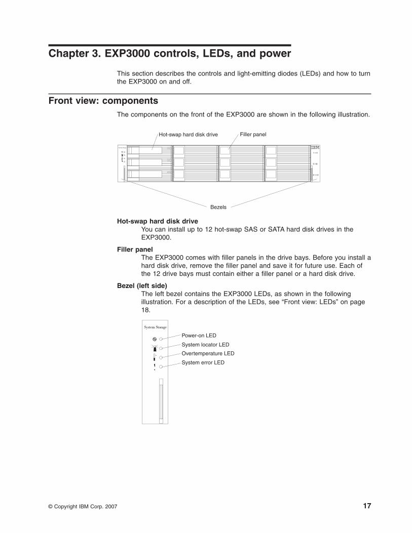
Front view: components
The components on the front of the EXP3000 are shown in the following illustration.
Hot-swap hard disk drive Filler panel
System Storage
Bezels
Hot-swap hard disk drive
You can install up to 12 hot-swap SAS or SATA hard disk drives in the
EXP3000.
Filler panel
The EXP3000 comes with filler panels in the drive bays. Before you install a
hard disk drive, remove the filler panel and save it for future use. Each of
the 12 drive bays must contain either a filler panel or a hard disk drive.
Bezel (left side)
The left bezel contains the EXP3000 LEDs, as shown in the following
illustration. For a description of the LEDs, see “Front view: LEDs” on page
18.
Power-on LED
System locator LED
System error LED
Overtemperature LED
© Copyright IBM Corp. 2007 17
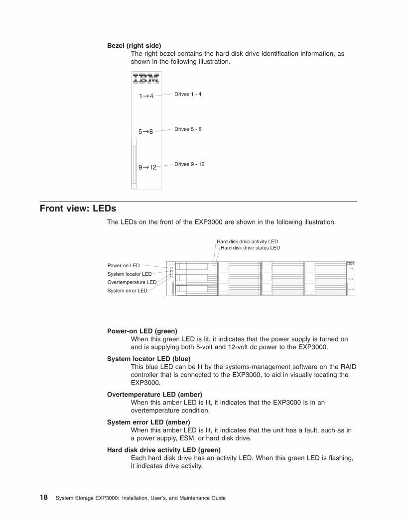
Bezel (right side)
The right bezel contains the hard disk drive identification information, as
shown in the following illustration.
Drives 1 - 4
Drives 5 - 8
Drives 9 - 12
Front view: LEDs
The LEDs on the front of the EXP3000 are shown in the following illustration.
Hard disk drive activity LEDHard disk drive status LED
System StoragePower-on LED
System locator LED
System error LED
Overtemperature LED
Power-on LED (green)
When this green LED is lit, it indicates that the power supply is turned on
and is supplying both 5-volt and 12-volt dc power to the EXP3000.
System locator LED (blue)
This blue LED can be lit by the systems-management software on the RAID
controller that is connected to the EXP3000, to aid in visually locating the
EXP3000.
Overtemperature LED (amber)
When this amber LED is lit, it indicates that the EXP3000 is in an
overtemperature condition.
System error LED (amber)
When this amber LED is lit, it indicates that the unit has a fault, such as in
a power supply, ESM, or hard disk drive.
Hard disk drive activity LED (green)
Each hard disk drive has an activity LED. When this green LED is flashing,
it indicates drive activity.
18 System Storage EXP3000: Installation, User’s, and Maintenance Guide
Hard disk drive status LED (amber)
Each hard disk drive has a status LED. When this amber LED is lit
continuously, it indicates a drive failure. When it is flashing, it indicates that
a drive Identify or Rebuild is in progress.
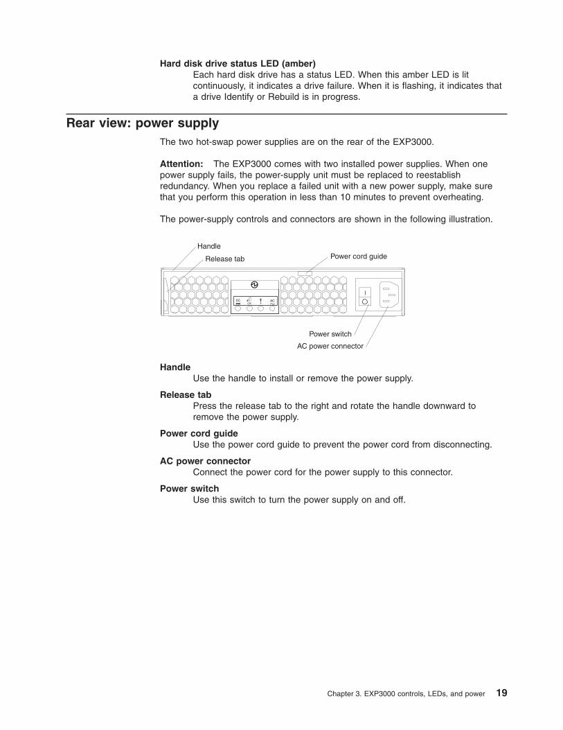
Rear view: power supply
The two hot-swap power supplies are on the rear of the EXP3000.
Attention: The EXP3000 comes with two installed power supplies. When one
power supply fails, the power-supply unit must be replaced to reestablish
redundancy. When you replace a failed unit with a new power supply, make sure
that you perform this operation in less than 10 minutes to prevent overheating.
The power-supply controls and connectors are shown in the following illustration.
Power switch
AC power connector
Handle
Release tab Power cord guide
Handle
Use the handle to install or remove the power supply.
Release tab
Press the release tab to the right and rotate the handle downward to
remove the power supply.
Power cord guide
Use the power cord guide to prevent the power cord from disconnecting.
AC power connector
Connect the power cord for the power supply to this connector.
Power switch
Use this switch to turn the power supply on and off.
Chapter 3. EXP3000 controls, LEDs, and power 19
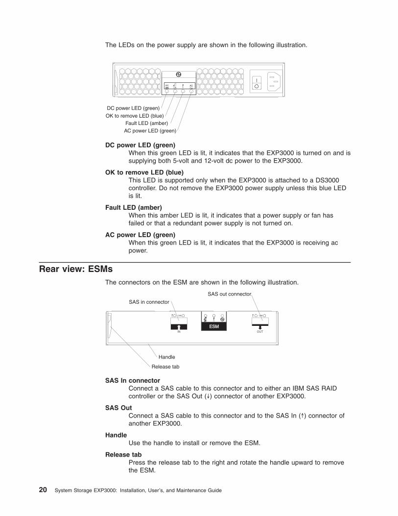
The LEDs on the power supply are shown in the following illustration.
Fault LED (amber)AC power LED (green)
OK to remove LED (blue)
DC power LED (green)
DC power LED (green)
When this green LED is lit, it indicates that the EXP3000 is turned on and is
supplying both 5-volt and 12-volt dc power to the EXP3000.
OK to remove LED (blue)
This LED is supported only when the EXP3000 is attached to a DS3000
controller. Do not remove the EXP3000 power supply unless this blue LED
is lit.
Fault LED (amber)
When this amber LED is lit, it indicates that a power supply or fan has
failed or that a redundant power supply is not turned on.
AC power LED (green)
When this green LED is lit, it indicates that the EXP3000 is receiving ac
power.
Rear view: ESMs
The connectors on the ESM are shown in the following illustration.
SAS in connector
SAS out connector
Handle
Release tab
SAS In connector
Connect a SAS cable to this connector and to either an IBM SAS RAID
controller or the SAS Out (↓) connector of another EXP3000.
SAS Out
Connect a SAS cable to this connector and to the SAS In (↑) connector of
another EXP3000.
Handle
Use the handle to install or remove the ESM.
Release tab
Press the release tab to the right and rotate the handle upward to remove
the ESM.
20 System Storage EXP3000: Installation, User’s, and Maintenance Guide
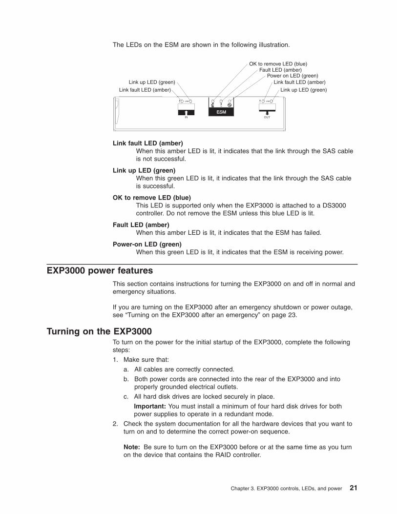
The LEDs on the ESM are shown in the following illustration.
OK to remove LED (blue)Fault LED (amber)
Power on LED (green)Link fault LED (amber)Link up LED (green)
Link up LED (green)Link fault LED (amber)
Link fault LED (amber)
When this amber LED is lit, it indicates that the link through the SAS cable
is not successful.
Link up LED (green)
When this green LED is lit, it indicates that the link through the SAS cable
is successful.
OK to remove LED (blue)
This LED is supported only when the EXP3000 is attached to a DS3000
controller. Do not remove the ESM unless this blue LED is lit.
Fault LED (amber)
When this amber LED is lit, it indicates that the ESM has failed.
Power-on LED (green)
When this green LED is lit, it indicates that the ESM is receiving power.
EXP3000 power features
This section contains instructions for turning the EXP3000 on and off in normal and
emergency situations.
If you are turning on the EXP3000 after an emergency shutdown or power outage,
see “Turning on the EXP3000 after an emergency” on page 23.
Turning on the EXP3000
To turn on the power for the initial startup of the EXP3000, complete the following
steps:
1. Make sure that:
a. All cables are correctly connected.
b. Both power cords are connected into the rear of the EXP3000 and into
properly grounded electrical outlets.
c. All hard disk drives are locked securely in place.
Important: You must install a minimum of four hard disk drives for both
power supplies to operate in a redundant mode.
2. Check the system documentation for all the hardware devices that you want to
turn on and to determine the correct power-on sequence.
Note: Be sure to turn on the EXP3000 before or at the same time as you turn
on the device that contains the RAID controller.
Chapter 3. EXP3000 controls, LEDs, and power 21
3. Turn on both power supplies on the rear of the unit.
The EXP3000 might take a few seconds to turn on. During this time, you might
see the EXP3000 amber fault LED, green power LED, power supply LEDs, and
blue system locator LED turn on and off intermittently. When the power-on
sequence is completed, only the green power LEDs on the front and rear should
remain lit. If one or more amber fault LEDs remain lit, see Chapter 5, “Solving
problems,” on page 37.
Turning off the EXP3000
Attention: Except in an emergency situation, never turn off the power if any fault
LEDs are lit on the EXP3000. Correct the fault before you attempt to turn off the
power, using the correct troubleshooting or servicing procedure. This ensures that
the EXP3000 turns on correctly later. For more information, see Chapter 5, “Solving
problems,” on page 37.
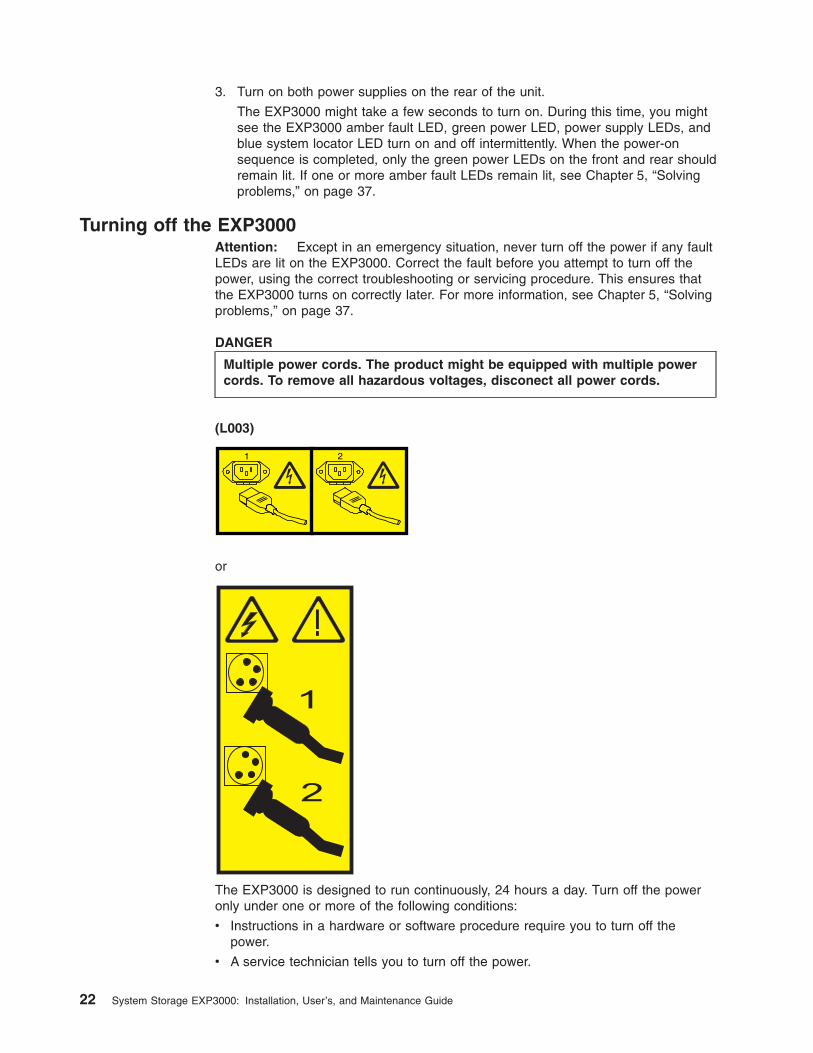
DANGER
Multiple power cords. The product might be equipped with multiple power
cords. To remove all hazardous voltages, disconect all power cords.
(L003)
1 2
or
!
1
2
The EXP3000 is designed to run continuously, 24 hours a day. Turn off the power
only under one or more of the following conditions:
v Instructions in a hardware or software procedure require you to turn off the
power.
v A service technician tells you to turn off the power.
22 System Storage EXP3000: Installation, User’s, and Maintenance Guide
v A power outage or emergency situation occurs. See “Turning off the EXP3000 in
an emergency.”
To turn off the EXP3000, complete the following steps:
1. Make sure that all amber status or fault LEDs on the EXP3000 are off. If any
status or fault LEDs are lit (on hard disk drives, power supplies, or ESMs),
identify or correct the problems before you turn off the power. For more
information, see Chapter 5, “Solving problems,” on page 37.
2. On the server to which the EXP3000 is connected, either directly or through
another supported device that contains a RAID controller to which the EXP3000
is connected, close all operating-system windows and programs; then, shut
down the server.
3. Shut down any device that contains a RAID controller to which the EXP3000 is
connected.
4. Turn off both EXP3000 power supplies.
Turning off the EXP3000 in an emergency
Attention: Emergency situations might include fire, flood, extreme weather
conditions, or other hazardous circumstances. If a power outage or emergency
situation occurs, always turn off all power switches on all computing equipment.
This will help safeguard your equipment from potential damage due to electrical
surges when power is restored. If the EXP3000 loses power unexpectedly, it might
be due to a hardware failure in the power system or midplane. See Chapter 5,
“Solving problems,” on page 37.
To turn off the EXP3000 during an emergency situation, complete the following
steps:
1. If you have time, stop all activity and check the LEDs (front and rear). Make
note of any status or fault LEDs that are lit so that you can correct the problem
when you turn on the power again.
Note: See the documentation that comes with your RAID controller for
information about correcting the problem.
2. On the server to which the EXP3000 is connected, either directly or through
another supported device that contains a RAID controller to which the EXP3000
is connected, close all operating-system windows and programs; then, shut
down the server.
3. Shut down any device that contains a RAID controller to which the EXP3000 is
connected.
4. Turn off both EXP3000 power supplies; then, disconnect the power cables from
the EXP3000.
Turning on the EXP3000 after an emergency
To restart the EXP3000 if you turned off the power supplies during an emergency
shutdown, or if a power failure or a power outage occurred, complete the following
steps:
1. After the emergency situation is over or power is restored, check the EXP3000
for damage. If there is no visible damage, continue with step 2; otherwise, have
your unit serviced.
2. Check the system documentation for the hardware devices that you intend to
turn on, and determine the correct power-on sequence.
Chapter 3. EXP3000 controls, LEDs, and power 23
Note: Be sure to turn on the EXP3000 before or at the same time you turn on
the device that contains the RAID controller to which the EXP3000 is
connected.
3. Turn on each connected device, according to the power-on sequence that is
described in the documentation that comes with the device.
4. Connect the EXP3000 power cables and turn on both power switches on the
rear of the EXP3000.
5. Make sure that only the power (green) LEDs on the front and rear are lit. If one
or more of the fault (amber) LEDs are lit, see Chapter 5, “Solving problems,” on
page 37 for instructions.
6. Use the RAID controller management software as applicable to check the status
of the EXP3000.
24 System Storage EXP3000: Installation, User’s, and Maintenance Guide
Chapter 4. Replacing components
This chapter contains information about IBM customer replaceable units (CRUs)
and field replaceable units (FRUs) for the EXP3000 and instructions for
replacement parts that are not installed during a typical installation.
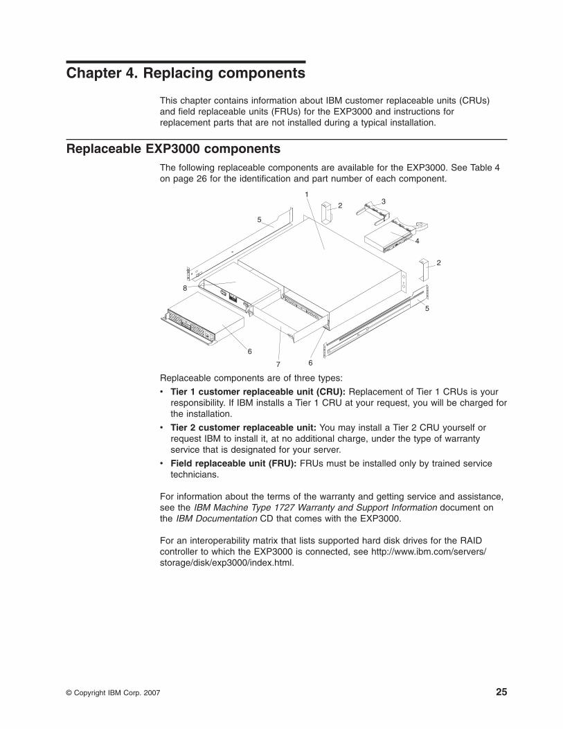
Replaceable EXP3000 components
The following replaceable components are available for the EXP3000. See Table 4
on page 26 for the identification and part number of each component.
1
2 3
4
5
5
6
6
7
8
2
Replaceable components are of three types:
v Tier 1 customer replaceable unit (CRU): Replacement of Tier 1 CRUs is your
responsibility. If IBM installs a Tier 1 CRU at your request, you will be charged for
the installation.
v Tier 2 customer replaceable unit: You may install a Tier 2 CRU yourself or
request IBM to install it, at no additional charge, under the type of warranty
service that is designated for your server.
v Field replaceable unit (FRU): FRUs must be installed only by trained service
technicians.
For information about the terms of the warranty and getting service and assistance,
see the IBM Machine Type 1727 Warranty and Support Information document on
the IBM Documentation CD that comes with the EXP3000.
For an interoperability matrix that lists supported hard disk drives for the RAID
controller to which the EXP3000 is connected, see http://www.ibm.com/servers/storage/disk/exp3000/index.html.
© Copyright IBM Corp. 2007 25
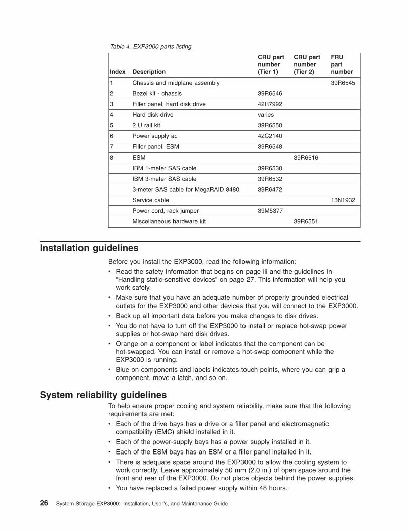
Table 4. EXP3000 parts listing
Index Description
CRU part
number
(Tier 1)
CRU part
number
(Tier 2)
FRU
part
number
1 Chassis and midplane assembly 39R6545
2 Bezel kit - chassis 39R6546
3 Filler panel, hard disk drive 42R7992
4 Hard disk drive varies
5 2 U rail kit 39R6550
6 Power supply ac 42C2140
7 Filler panel, ESM 39R6548
8 ESM 39R6516
IBM 1-meter SAS cable 39R6530
IBM 3-meter SAS cable 39R6532
3-meter SAS cable for MegaRAID 8480 39R6472
Service cable 13N1932
Power cord, rack jumper 39M5377
Miscellaneous hardware kit 39R6551
Installation guidelines
Before you install the EXP3000, read the following information:
v Read the safety information that begins on page iii and the guidelines in
“Handling static-sensitive devices” on page 27. This information will help you
work safely.
v Make sure that you have an adequate number of properly grounded electrical
outlets for the EXP3000 and other devices that you will connect to the EXP3000.
v Back up all important data before you make changes to disk drives.
v You do not have to turn off the EXP3000 to install or replace hot-swap power
supplies or hot-swap hard disk drives.
v Orange on a component or label indicates that the component can be
hot-swapped. You can install or remove a hot-swap component while the
EXP3000 is running.
v Blue on components and labels indicates touch points, where you can grip a
component, move a latch, and so on.
System reliability guidelines
To help ensure proper cooling and system reliability, make sure that the following
requirements are met:
v Each of the drive bays has a drive or a filler panel and electromagnetic
compatibility (EMC) shield installed in it.
v Each of the power-supply bays has a power supply installed in it.
v Each of the ESM bays has an ESM or a filler panel installed in it.
v There is adequate space around the EXP3000 to allow the cooling system to
work correctly. Leave approximately 50 mm (2.0 in.) of open space around the
front and rear of the EXP3000. Do not place objects behind the power supplies.
v You have replaced a failed power supply within 48 hours.
26 System Storage EXP3000: Installation, User’s, and Maintenance Guide
v You have replaced a hot-swap hard disk drive within 2 minutes of removal with a
new drive or filler panel.
Handling static-sensitive devices
Attention: Static electricity can damage the EXP3000 and other electronic
devices. To avoid damage, keep static-sensitive devices in their static-protective
packages until you are ready to install them.
To reduce the possibility of damage from electrostatic discharge, observe the
following precautions:
v Limit your movement. Movement can cause static electricity to build up around
you.
v Handle the device carefully, holding it by its edges or its frame.
v Do not touch solder joints, pins, or exposed circuitry.
v Do not leave the device where others can handle and damage it.
v While the device is still in its static-protective package, touch it to an unpainted
metal part of the EXP3000 for at least 2 seconds. This drains static electricity
from the package and from your body.
v Remove the device from its package and install it directly into the EXP3000
without setting down the device. If it is necessary to set down the device, put it
back into its static-protective package. Do not place the device on the EXP3000
or on a metal surface.
v Take additional care when you handle devices during cold weather. Heating
reduces indoor humidity and increases static electricity.
Working with hot-swap hard disk drives
Before you remove a hard disk drive, review the following information:
Hot-swap hardware
You can replace a failed hard disk drive without turning off the EXP3000.
Therefore, you can continue to operate the EXP3000 while a hard disk
drive is removed or installed. These drives are known as hot-swap drives.
Hard disk drives
The EXP3000 supports IBM SAS or SATA hard disk drives. Each drive
comes preinstalled in a drive tray, ready for installation in the EXP3000. (Do
not detach the drive from the tray.) You can install the drives directly into
the 12 drive bays on the front of the EXP3000. Before you remove any
drives, record the location information for each drive in Table 2 on page 3.
Attention: If you remove a drive, you must reinstall it in the same bay. If
you reinstall a hard disk drive in the wrong bay, you might lose data.
Hard disk drive LEDs
Each hard disk drive has two LEDs that indicate the status of the drive. The
drive LED states and descriptions are shown in the following table.
LED LED state Description
Activity (green) Flashing Flashes during read/write
or inquiry operations to the
hard disk drive
Chapter 4. Replacing components 27
LED LED state Description
Status (amber) Flashing Flashes to indicate that the
hard disk drive is being
rebuilt or that the hard disk
drive has been identified
by the RAID controller
management software
Status (amber) Lit Is lit continuously to
indicate a drive failure
Replacing a hot-swap hard disk drive
Hard disk drive problems include any malfunctions that delay, interrupt, or prevent
successful I/O activity between the hosts and the hard disk drives in the EXP3000.
This includes transmission problems between the host controllers, the ESMs, and
the drives. This section explains how to replace a failed drive.
Check the hardware and software documentation that comes with your server to
determine whether there are restrictions regarding hard disk drive configurations.
Some system configurations might not allow mixing different hard disk drive
capacities or types within an array.
To replace a hot-swap hard disk drive, complete the following steps:
1. Read the instructions that come with the hard disk drive.
2. Read the safety information that begins on page iii and “Installation guidelines”
on page 26.
3. Locate the hard disk drive that you want to remove.
Attention: Never hot-swap a hard disk drive when its green activity LED is
flashing. Hot-swap a drive only when its amber status LED is lit (not flashing) or
when the drive is inactive (activity LED is off).
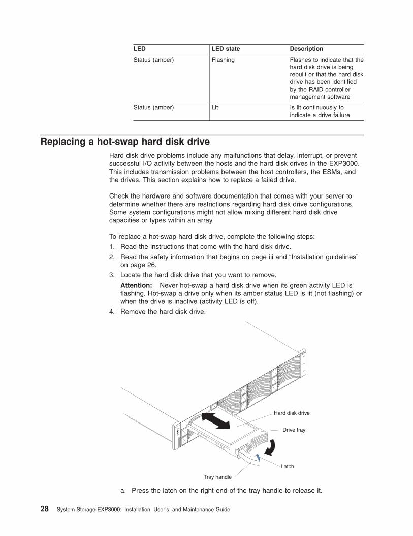
4. Remove the hard disk drive.
Drive tray
Tray handle
Latch
Hard disk drive
System
Storage
a. Press the latch on the right end of the tray handle to release it.
28 System Storage EXP3000: Installation, User’s, and Maintenance Guide
b. Pull out the tray handle to the open position.
c. Slide the drive partially out of the bay and wait at least 20 seconds before
you remove the drive from the EXP3000. This enables the drive to spin
down and avoids possible damage to the drive.
d. Make sure that there is proper identification (such as a label) on the hard
disk drive; then, gently slide it completely out of the EXP3000. If the drive
has failed, indicate that on the label.
5. Install the new hard disk drive:
a. Gently push the drive into the empty bay until the drive stops.
b. Push the tray handle to the right into the closed (latched) position.
6. Check the hard disk drive LEDs:
v When the drive is ready for use, the green activity LED and the amber status
LED are off.
v If the amber status LED is lit and not flashing, remove the drive from the unit
and wait 10 seconds; then, reinstall the drive. If the status LED is flashing,
the drive is rebuilding.
Controller management information: In some cases, the RAID controller automatically
resets the drive to the Hot Spare or Rebuild state. If the drive state does not change
automatically (the amber LED stays lit), see your RAID controller management
documentation for information about manually changing the state of the drive from the
current state to another state, such as Hot Spare or Ready. The amber LED should turn off
within 10 seconds after the drive state changes.
Replacing an ESM
If you are replacing the only ESM in the EXP3000, you must turn off power to the
EXP3000 before you replace the ESM. Refer to the documentation that comes with
your RAID controller for additional information and instructions.
To replace an ESM, complete the following steps:
1. Read the safety information that begins on page iii and “Installation guidelines”
on page 26.
2. If the EXP3000 contains only one ESM, turn off the power to the EXP3000.
For more information, see “Turning off the EXP3000” on page 22.
3. Disconnect the SAS cable from the ESM.
4. On the left side of the ESM, press the orange release tab to the right just
enough to release the handle (no more than 6 mm [0.25 in.]) as you rotate the
handle upward.
Chapter 4. Replacing components 29
ESM
Handle
Release tab
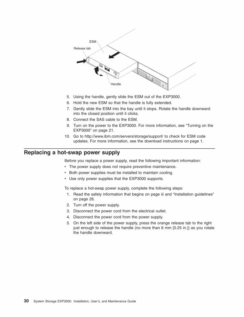
5. Using the handle, gently slide the ESM out of the EXP3000.
6. Hold the new ESM so that the handle is fully extended.
7. Gently slide the ESM into the bay until it stops. Rotate the handle downward
into the closed position until it clicks.
8. Connect the SAS cable to the ESM.
9. Turn on the power to the EXP3000. For more information, see “Turning on the
EXP3000” on page 21.
10. Go to http://www.ibm.com/servers/storage/support/ to check for ESM code
updates. For more information, see the download instructions on page 1.
Replacing a hot-swap power supply
Before you replace a power supply, read the following important information:
v The power supply does not require preventive maintenance.
v Both power supplies must be installed to maintain cooling.
v Use only power supplies that the EXP3000 supports.
To replace a hot-swap power supply, complete the following steps:
1. Read the safety information that begins on page iii and “Installation guidelines”
on page 26.
2. Turn off the power supply.
3. Disconnect the power cord from the electrical outlet.
4. Disconnect the power cord from the power supply.
5. On the left side of the power supply, press the orange release tab to the right
just enough to release the handle (no more than 6 mm [0.25 in.]) as you rotate
the handle downward.
30 System Storage EXP3000: Installation, User’s, and Maintenance Guide
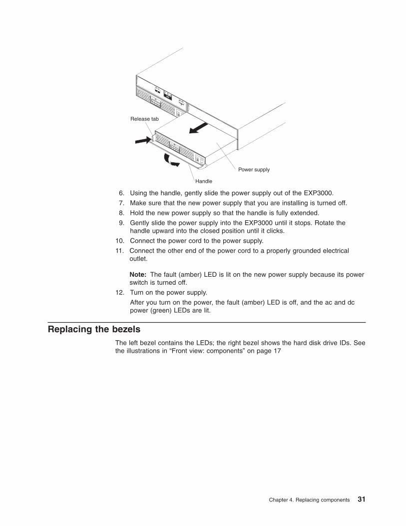
Handle
Release tab
Power supply
6. Using the handle, gently slide the power supply out of the EXP3000.
7. Make sure that the new power supply that you are installing is turned off.
8. Hold the new power supply so that the handle is fully extended.
9. Gently slide the power supply into the EXP3000 until it stops. Rotate the
handle upward into the closed position until it clicks.
10. Connect the power cord to the power supply.
11. Connect the other end of the power cord to a properly grounded electrical
outlet.
Note: The fault (amber) LED is lit on the new power supply because its power
switch is turned off.
12. Turn on the power supply.
After you turn on the power, the fault (amber) LED is off, and the ac and dc
power (green) LEDs are lit.
Replacing the bezels
The left bezel contains the LEDs; the right bezel shows the hard disk drive IDs. See
the illustrations in “Front view: components” on page 17
Chapter 4. Replacing components 31
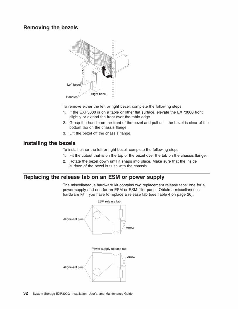
Removing the bezels
Right bezel
Left bezel
Handles
To remove either the left or right bezel, complete the following steps:
1. If the EXP3000 is on a table or other flat surface, elevate the EXP3000 front
slightly or extend the front over the table edge.
2. Grasp the handle on the front of the bezel and pull until the bezel is clear of the
bottom tab on the chassis flange.
3. Lift the bezel off the chassis flange.
Installing the bezels
To install either the left or right bezel, complete the following steps:
1. Fit the cutout that is on the top of the bezel over the tab on the chassis flange.
2. Rotate the bezel down until it snaps into place. Make sure that the inside
surface of the bezel is flush with the chassis.
Replacing the release tab on an ESM or power supply
The miscellaneous hardware kit contains two replacement release tabs: one for a
power supply and one for an ESM or ESM filler panel. Obtain a miscellaneous
hardware kit if you have to replace a release tab (see Table 4 on page 26).
ESM release tab
Power-supply release tab
Alignment pins
Alignment pins
Arrow
Arrow
32 System Storage EXP3000: Installation, User’s, and Maintenance Guide
Before you replace a release tab, read the following important information:
v In this procedure, the term ESM refers to an ESM or ESM filler panel.
v Make sure that you have a size #1 or #0 Phillips screwdriver.
To replace a release tab, complete the following steps:
1. Read the safety information that begins on page iii and “Installation guidelines”
on page 26.
2. Make sure that it is safe to proceed:
v If you are replacing the release tab on the only ESM in the EXP3000, make
sure that the EXP3000 is shut down for maintenance.
v If you are replacing a power-supply release tab, make sure that the power
supplies are providing redundant power (on both power supplies, the ac
power LED and dc power LEDs are lit, and the fault LED is off). If the power
supplies are not providing redundant power, resolve the redundancy problem
first, or wait until the EXP3000 is shut down for maintenance, before you
replace the release tab.
3. Remove the ESM or power supply from the EXP3000 chassis. See “Replacing
an ESM” on page 29 or “Replacing a hot-swap power supply” on page 30.
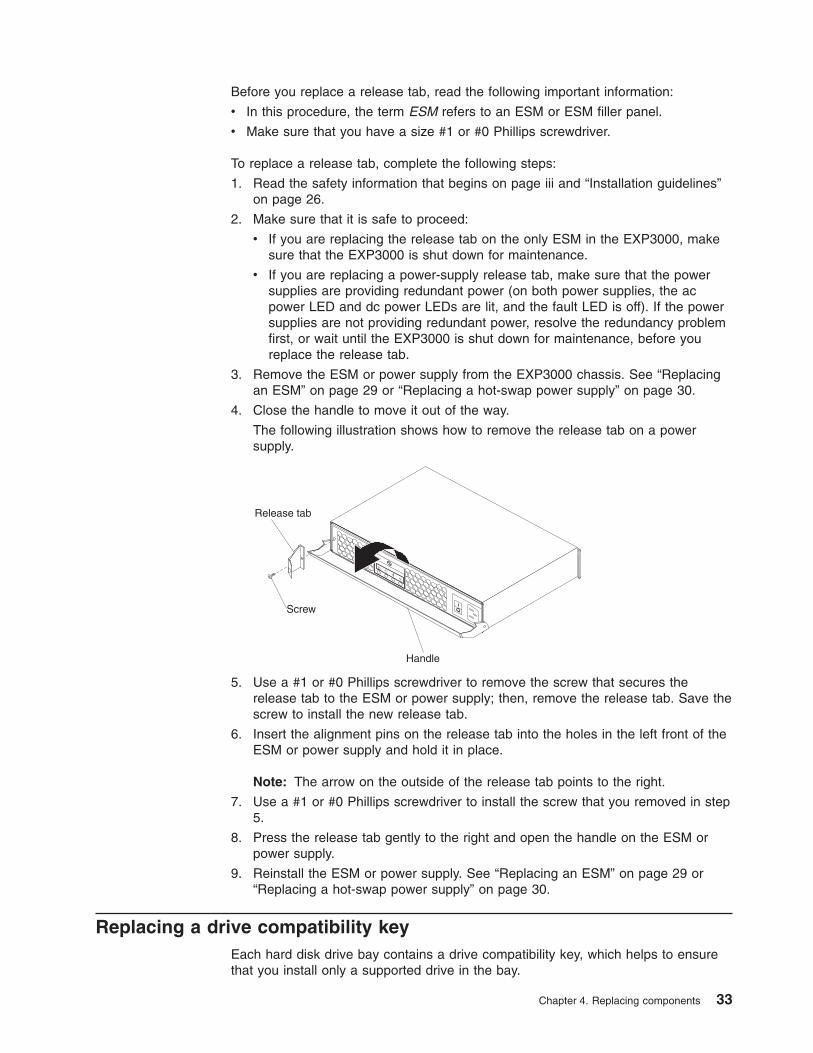
4. Close the handle to move it out of the way.
The following illustration shows how to remove the release tab on a power
supply.
Handle
Release tab
Screw
5. Use a #1 or #0 Phillips screwdriver to remove the screw that secures the
release tab to the ESM or power supply; then, remove the release tab. Save the
screw to install the new release tab.
6. Insert the alignment pins on the release tab into the holes in the left front of the
ESM or power supply and hold it in place.
Note: The arrow on the outside of the release tab points to the right.
7. Use a #1 or #0 Phillips screwdriver to install the screw that you removed in step
5.
8. Press the release tab gently to the right and open the handle on the ESM or
power supply.
9. Reinstall the ESM or power supply. See “Replacing an ESM” on page 29 or
“Replacing a hot-swap power supply” on page 30.
Replacing a drive compatibility key
Each hard disk drive bay contains a drive compatibility key, which helps to ensure
that you install only a supported drive in the bay.
Chapter 4. Replacing components 33
Important: Do not attempt to install any hard disk drive other than a supported
drive in any hard disk drive bay. See http://www.ibm.com/servers/storage/disk/exp3000/index.html for information about the EXP3000 and an interoperability
matrix that lists supported hard disk drives.
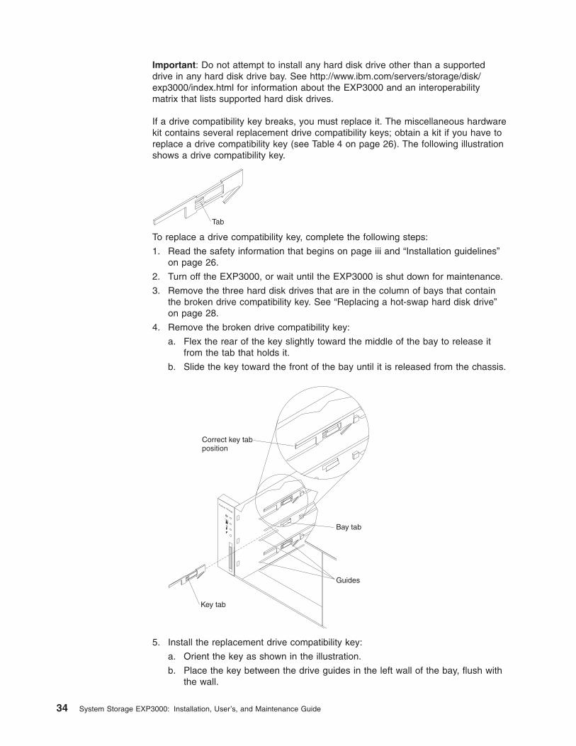
If a drive compatibility key breaks, you must replace it. The miscellaneous hardware
kit contains several replacement drive compatibility keys; obtain a kit if you have to
replace a drive compatibility key (see Table 4 on page 26). The following illustration
shows a drive compatibility key.
Tab
To replace a drive compatibility key, complete the following steps:
1. Read the safety information that begins on page iii and “Installation guidelines”
on page 26.
2. Turn off the EXP3000, or wait until the EXP3000 is shut down for maintenance.
3. Remove the three hard disk drives that are in the column of bays that contain
the broken drive compatibility key. See “Replacing a hot-swap hard disk drive”
on page 28.
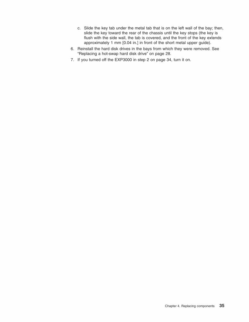
4. Remove the broken drive compatibility key:
a. Flex the rear of the key slightly toward the middle of the bay to release it
from the tab that holds it.
b. Slide the key toward the front of the bay until it is released from the chassis.
System Storage
Key tab
Bay tab
Guides
Correct key tabposition
5. Install the replacement drive compatibility key:
a. Orient the key as shown in the illustration.
b. Place the key between the drive guides in the left wall of the bay, flush with
the wall.
34 System Storage EXP3000: Installation, User’s, and Maintenance Guide
c. Slide the key tab under the metal tab that is on the left wall of the bay; then,
slide the key toward the rear of the chassis until the key stops (the key is
flush with the side wall, the tab is covered, and the front of the key extends
approximately 1 mm [0.04 in.] in front of the short metal upper guide).
6. Reinstall the hard disk drives in the bays from which they were removed. See
“Replacing a hot-swap hard disk drive” on page 28.
7. If you turned off the EXP3000 in step 2 on page 34, turn it on.
Chapter 4. Replacing components 35

36 System Storage EXP3000: Installation, User’s, and Maintenance Guide
Chapter 5. Solving problems
The following table contains troubleshooting information to help you solve some
basic problems that you might have with the EXP3000.
Table 5. Troubleshooting information
Component Problem indicator Possible cause Possible solutions
Hard disk drive Amber fault LED lit Drive failure Replace the failed hard disk drive. See “Replacing a
hot-swap hard disk drive” on page 28.
ESM Board failure Replace the failed ESM. See “Replacing an ESM”
on page 29.
Front panel General machine
fault
A status or fault LED somewhere on the EXP3000
is lit. Check for amber LEDs on components. See
Chapter 3, “EXP3000 controls, LEDs, and power,”
on page 17.
All components All green LEDs off The EXP3000 is
turned off
Make sure that all EXP3000 power cables are
connected and that the power is on. If applicable,
make sure that the main circuit breakers for the rack
are turned on.
ac or dc power
failure
Check the main circuit breaker and ac or dc outlet.
Power-supply
failure
Replace the power supply. See “Replacing a
hot-swap power supply” on page 30.
Midplane failure Have the EXP3000 serviced.
Hard disk drives Amber fault LED
flashing
Drive rebuild or
identity in process
No action is required.
Power supply Amber fault LED lit;
green dc power LED
off
Power supply
failure; power
supply turned off;
minimum hard disk
drives not installed
1. Install four or more hard disk drives, turn off the
power, and turn it on again.
2. If the power-supply switch is on, turn off the
power supply and then turn it on again. If the
condition remains, replace the power supply.
See “Replacing a hot-swap power supply” on
page 30.
Power supply Amber fault LED lit;
green ac power LED
off
No ac power to
power supply
Check the ac power cord or breaker.
v If ac power is good at the source, replace the
power cord.
v If the power supply has failed, replace the power
supply. See “Replacing a hot-swap power supply”
on page 30.
ESM Link fault amber LED
lit
SAS
communication
failure
1. Reconnect the SAS cable.
2. Replace the SAS cable.
3. If the LED is still lit, replace either the ESM or
the controller or device into which the other end
of the SAS cable is connected.
© Copyright IBM Corp. 2007 37
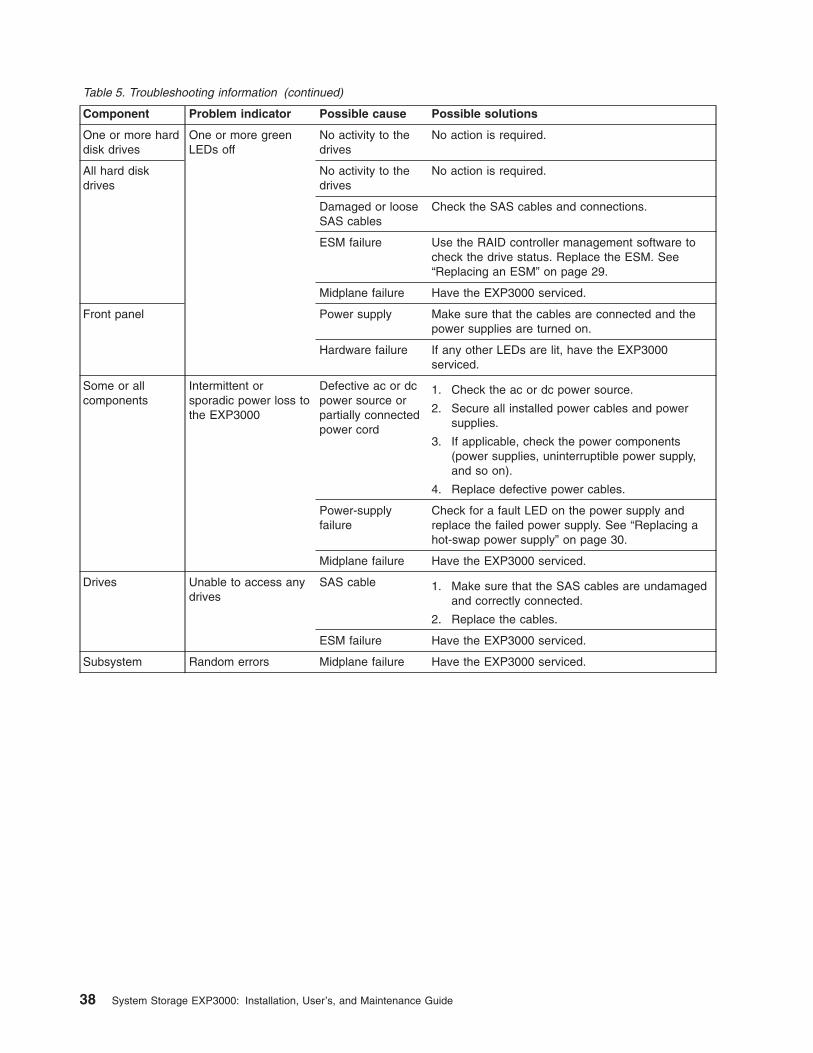
Table 5. Troubleshooting information (continued)
Component Problem indicator Possible cause Possible solutions
One or more hard
disk drives
One or more green
LEDs off
No activity to the
drives
No action is required.
All hard disk
drives
No activity to the
drives
No action is required.
Damaged or loose
SAS cables
Check the SAS cables and connections.
ESM failure Use the RAID controller management software to
check the drive status. Replace the ESM. See
“Replacing an ESM” on page 29.
Midplane failure Have the EXP3000 serviced.
Front panel Power supply Make sure that the cables are connected and the
power supplies are turned on.
Hardware failure If any other LEDs are lit, have the EXP3000
serviced.
Some or all
components
Intermittent or
sporadic power loss to
the EXP3000
Defective ac or dc
power source or
partially connected
power cord
1. Check the ac or dc power source.
2. Secure all installed power cables and power
supplies.
3. If applicable, check the power components
(power supplies, uninterruptible power supply,
and so on).
4. Replace defective power cables.
Power-supply
failure
Check for a fault LED on the power supply and
replace the failed power supply. See “Replacing a
hot-swap power supply” on page 30.
Midplane failure Have the EXP3000 serviced.
Drives Unable to access any
drives
SAS cable 1. Make sure that the SAS cables are undamaged
and correctly connected.
2. Replace the cables.
ESM failure Have the EXP3000 serviced.
Subsystem Random errors Midplane failure Have the EXP3000 serviced.
38 System Storage EXP3000: Installation, User’s, and Maintenance Guide
Appendix A. Getting help and technical assistance
If you need help, service, or technical assistance or just want more information
about IBM products, you will find a wide variety of sources available from IBM to
assist you. This section contains information about where to go for additional
information about IBM and IBM products, what to do if you experience a problem
with your system, and whom to call for service, if it is necessary.
Before you call
Before you call, make sure that you have taken these steps to try to solve the
problem yourself:
v Check all cables to make sure that they are connected.
v Check the power switches to make sure that the system and any optional
devices are turned on.
v Use the troubleshooting information in your system documentation, and use the
diagnostic tools that come with your system. Information about diagnostic tools is
in the Problem Determination and Service Guide on the IBM Documentation CD
that comes with your system.
v Go to the IBM support Web site at http://www.ibm.com/systems/support/ to check
for technical information, hints, tips, and new device drivers or to submit a
request for information.
You can solve many problems without outside assistance by following the
troubleshooting procedures that IBM provides in the online help or in the
documentation that is provided with your IBM product. The documentation that
comes with IBM systems also describes the diagnostic tests that you can perform.
Most systems, operating systems, and programs come with documentation that
contains troubleshooting procedures and explanations of error messages and error
codes. If you suspect a software problem, see the documentation for the operating
system or program.
Using the documentation
Information about your IBM system and preinstalled software, if any, or optional
device is available in the documentation that comes with the product. That
documentation can include printed documents, online documents, readme files, and
help files. See the troubleshooting information in your system documentation for
instructions for using the diagnostic programs. The troubleshooting information or
the diagnostic programs might tell you that you need additional or updated device
drivers or other software. IBM maintains pages on the World Wide Web where you
can get the latest technical information and download device drivers and updates.
To access these pages, go to http://www.ibm.com/systems/support/ and follow the
instructions. Also, some documents are available through the IBM Publications
Center at http://www.ibm.com/shop/publications/order/.
Getting help and information from the World Wide Web
On the World Wide Web, the IBM Web site has up-to-date information about IBM
systems, optional devices, services, and support. The address for IBM System x™
and xSeries® information is http://www.ibm.com/systems/x/. The address for IBM
BladeCenter® information is http://www.ibm.com/systems/bladecenter/. The address
for IBM IntelliStation® information is http://www.ibm.com/intellistation/.
© Copyright IBM Corp. 2007 39
You can find service information for IBM systems and optional devices at
http://www.ibm.com/systems/support/.
Software service and support
Through IBM Support Line, you can get telephone assistance, for a fee, with usage,
configuration, and software problems with System x and xSeries servers,
BladeCenter products, IntelliStation workstations, and appliances. For information
about which products are supported by Support Line in your country or region, see
http://www.ibm.com/services/sl/products/.
For more information about Support Line and other IBM services, see
http://www.ibm.com/services/, or see http://www.ibm.com/planetwide/ for support
telephone numbers. In the U.S. and Canada, call 1-800-IBM-SERV
(1-800-426-7378).
Hardware service and support
You can receive hardware service through IBM Services or through your IBM
reseller, if your reseller is authorized by IBM to provide warranty service. See
http://www.ibm.com/planetwide/ for support telephone numbers, or in the U.S. and
Canada, call 1-800-IBM-SERV (1-800-426-7378).
In the U.S. and Canada, hardware service and support is available 24 hours a day,
7 days a week. In the U.K., these services are available Monday through Friday,
from 9 a.m. to 6 p.m.
IBM Taiwan product service
IBM Taiwan product service contact information:
IBM Taiwan Corporation
3F, No 7, Song Ren Rd.
Taipei, Taiwan
Telephone: 0800-016-888
40 System Storage EXP3000: Installation, User’s, and Maintenance Guide
Appendix B. Notices
This information was developed for products and services offered in the U.S.A.
IBM may not offer the products, services, or features discussed in this document in
other countries. Consult your local IBM representative for information on the
products and services currently available in your area. Any reference to an IBM
product, program, or service is not intended to state or imply that only that IBM
product, program, or service may be used. Any functionally equivalent product,
program, or service that does not infringe any IBM intellectual property right may be
used instead. However, it is the user’s responsibility to evaluate and verify the
operation of any non-IBM product, program, or service.
IBM may have patents or pending patent applications covering subject matter
described in this document. The furnishing of this document does not give you any
license to these patents. You can send license inquiries, in writing, to:
IBM Director of Licensing
IBM Corporation
North Castle Drive
Armonk, NY 10504-1785
U.S.A.
INTERNATIONAL BUSINESS MACHINES CORPORATION PROVIDES THIS
PUBLICATION “AS IS” WITHOUT WARRANTY OF ANY KIND, EITHER EXPRESS
OR IMPLIED, INCLUDING, BUT NOT LIMITED TO, THE IMPLIED WARRANTIES
OF NON-INFRINGEMENT, MERCHANTABILITY OR FITNESS FOR A
PARTICULAR PURPOSE. Some states do not allow disclaimer of express or
implied warranties in certain transactions, therefore, this statement may not apply to
you.
This information could include technical inaccuracies or typographical errors.
Changes are periodically made to the information herein; these changes will be
incorporated in new editions of the publication. IBM may make improvements and/or
changes in the product(s) and/or the program(s) described in this publication at any
time without notice.
Any references in this information to non-IBM Web sites are provided for
convenience only and do not in any manner serve as an endorsement of those
Web sites. The materials at those Web sites are not part of the materials for this
IBM product, and use of those Web sites is at your own risk.
IBM may use or distribute any of the information you supply in any way it believes
appropriate without incurring any obligation to you.
Trademarks
The following terms are trademarks of International Business Machines Corporation
in the United States, other countries, or both:
IBM FlashCopy TechConnect
IBM (logo) i5/OS Tivoli
Active Memory IntelliStation Tivoli Enterprise
Active PCI NetBAY Update Connector
Active PCI-X Netfinity Wake on LAN
© Copyright IBM Corp. 2007 41
AIX PowerExecutive XA-32
Alert on LAN Predictive Failure Analysis XA-64
BladeCenter ServeRAID X-Architecture
Chipkill ServerGuide XpandOnDemand
e-business logo ServerProven xSeries
Eserver System x
Intel, Intel Xeon, Itanium, and Pentium are trademarks or registered trademarks of
Intel Corporation or its subsidiaries in the United States and other countries.
Microsoft, Windows, and Windows NT are trademarks of Microsoft Corporation in
the United States, other countries, or both.
Adobe and PostScript are either registered trademarks or trademarks of Adobe
Systems Incorporated in the United States, other countries, or both.
UNIX is a registered trademark of The Open Group in the United States and other
countries.
Java and all Java-based trademarks are trademarks of Sun Microsystems, Inc. in
the United States, other countries, or both.
Adaptec and HostRAID are trademarks of Adaptec, Inc., in the United States, other
countries, or both.
Linux is a registered trademark of Linus Torvalds in the United States, other
countries, or both.
Red Hat, the Red Hat “Shadow Man” logo, and all Red Hat-based trademarks and
logos are trademarks or registered trademarks of Red Hat, Inc., in the United States
and other countries.
Other company, product, or service names may be trademarks or service marks of
others.
Important notes
Processor speed indicates the internal clock speed of the microprocessor; other
factors also affect application performance.
CD or DVD drive speed is the variable read rate. Actual speeds vary and are often
less than the possible maximum.
When referring to processor storage, real and virtual storage, or channel volume,
KB stands for 1024 bytes, MB stands for 1 048 576 bytes, and GB stands for
1 073 741 824 bytes.
When referring to hard disk drive capacity or communications volume, MB stands
for 1 000 000 bytes, and GB stands for 1 000 000 000 bytes. Total user-accessible
capacity can vary depending on operating environments.
Maximum internal hard disk drive capacities assume the replacement of any
standard hard disk drives and population of all hard disk drive bays with the largest
currently supported drives that are available from IBM.
42 System Storage EXP3000: Installation, User’s, and Maintenance Guide
Maximum memory might require replacement of the standard memory with an
optional memory module.
IBM makes no representation or warranties regarding non-IBM products and
services that are ServerProven®, including but not limited to the implied warranties
of merchantability and fitness for a particular purpose. These products are offered
and warranted solely by third parties.
IBM makes no representations or warranties with respect to non-IBM products.
Support (if any) for the non-IBM products is provided by the third party, not IBM.
Some software might differ from its retail version (if available) and might not include
user manuals or all program functionality.
Product recycling and disposal
This unit must be recycled or discarded according to applicable local and national
regulations. IBM encourages owners of information technology (IT) equipment to
responsibly recycle their equipment when it is no longer needed. IBM offers a
variety of product return programs and services in several countries to assist
equipment owners in recycling their IT products. Information on IBM product
recycling offerings can be found on IBM’s Internet site at http://www.ibm.com/ibm/environment/products/index.shtml.
Esta unidad debe reciclarse o desecharse de acuerdo con lo establecido en la
normativa nacional o local aplicable. IBM recomienda a los propietarios de equipos
de tecnología de la información (TI) que reciclen responsablemente sus equipos
cuando éstos ya no les sean útiles. IBM dispone de una serie de programas y
servicios de devolución de productos en varios países, a fin de ayudar a los
propietarios de equipos a reciclar sus productos de TI. Se puede encontrar
información sobre las ofertas de reciclado de productos de IBM en el sitio web de
IBM http://www.ibm.com/ibm/environment/products/index.shtml.
Notice: This mark applies only to countries within the European Union (EU) and
Norway.
This appliance is labeled in accordance with European Directive 2002/96/EC
concerning waste electrical and electronic equipment (WEEE). The Directive
determines the framework for the return and recycling of used appliances as
applicable throughout the European Union. This label is applied to various products
to indicate that the product is not to be thrown away, but rather reclaimed upon end
of life per this Directive.
Appendix B. Notices 43
Remarque : Cette marque s’applique uniquement aux pays de l’Union Européenne
et à la Norvège.
L’etiquette du système respecte la Directive européenne 2002/96/EC en matière de
Déchets des Equipements Electriques et Electroniques (DEEE), qui détermine les
dispositions de retour et de recyclage applicables aux systèmes utilisés à travers
l’Union européenne. Conformément à la directive, ladite étiquette précise que le
produit sur lequel elle est apposée ne doit pas être jeté mais être récupéré en fin
de vie.
In accordance with the European WEEE Directive, electrical and electronic
equipment (EEE) is to be collected separately and to be reused, recycled, or
recovered at end of life. Users of EEE with the WEEE marking per Annex IV of the
WEEE Directive, as shown above, must not dispose of end of life EEE as unsorted
municipal waste, but use the collection framework available to customers for the
return, recycling, and recovery of WEEE. Customer participation is important to
minimize any potential effects of EEE on the environment and human health due to
the potential presence of hazardous substances in EEE. For proper collection and
treatment, contact your local IBM representative.
Battery return program
This product may contain a sealed lead acid, nickel cadmium, nickel metal hydride,
lithium, or lithium ion battery. Consult your user manual or service manual for
specific battery information. The battery must be recycled or disposed of properly.
Recycling facilities may not be available in your area. For information on disposal of
batteries outside the United States, go to http://www.ibm.com/ibm/environment/products/index.shtml or contact your local waste disposal facility.
In the United States, IBM has established a return process for reuse, recycling, or
proper disposal of used IBM sealed lead acid, nickel cadmium, nickel metal hydride,
and battery packs from IBM equipment. For information on proper disposal of these
batteries, contact IBM at 1-800-426-4333. Have the IBM part number listed on the
battery available prior to your call.
For Taiwan: Please recycle batteries.
For the European Union:
44 System Storage EXP3000: Installation, User’s, and Maintenance Guide
Notice: This mark applies only to countries within the European Union (EU).
Batteries or packaging for batteries are labeled in accordance with European
Directive 2006/66/EC concerning batteries and accumulators and waste batteries
and accumulators. The Directive determines the framework for the return and
recycling of used batteries and accumulators as applicable throughout the European
Union. This label is applied to various batteries to indicate that the battery is not to
be thrown away, but rather reclaimed upon end of life per this Directive.
Les batteries ou emballages pour batteries sont étiquetés conformément aux
directives européennes 2006/66/EC, norme relative aux batteries et accumulateurs
en usage et aux batteries et accumulateurs usés. Les directives déterminent la
marche à suivre en vigueur dans l'Union Européenne pour le retour et le recyclage
des batteries et accumulateurs usés. Cette étiquette est appliquée sur diverses
batteries pour indiquer que la batterie ne doit pas être mise au rebut mais plutôt
récupérée en fin de cycle de vie selon cette norme.
In accordance with the European Directive 2006/66/EC, batteries and accumulators
are labeled to indicate that they are to be collected separately and recycled at end
of life. The label on the battery may also include a chemical symbol for the metal
concerned in the battery (Pb for lead, Hg for mercury, and Cd for cadmium). Users
of batteries and accumulators must not dispose of batteries and accumulators as
unsorted municipal waste, but use the collection framework available to customers
for the return, recycling, and treatment of batteries and accumulators. Customer
participation is important to minimize any potential effects of batteries and
accumulators on the environment and human health due to the potential presence
of hazardous substances. For proper collection and treatment, contact your local
IBM representative.
For California:
Perchlorate material – special handling may apply. See http://www.dtsc.ca.gov/hazardouswaste/perchlorate/.
The foregoing notice is provided in accordance with California Code of Regulations
Title 22, Division 4.5 Chapter 33. Best Management Practices for Perchlorate
Materials. This product/part may include a lithium manganese dioxide battery which
contains a perchlorate substance.
Appendix B. Notices 45

Electronic emission notices
Federal Communications Commission (FCC) statement
Note: This equipment has been tested and found to comply with the limits for a
Class A digital device, pursuant to Part 15 of the FCC Rules. These limits are
designed to provide reasonable protection against harmful interference when the
equipment is operated in a commercial environment. This equipment generates,
uses, and can radiate radio frequency energy and, if not installed and used in
accordance with the instruction manual, may cause harmful interference to radio
communications. Operation of this equipment in a residential area is likely to cause
harmful interference, in which case the user will be required to correct the
interference at his own expense.
Properly shielded and grounded cables and connectors must be used in order to
meet FCC emission limits. IBM is not responsible for any radio or television
interference caused by using other than recommended cables and connectors or by
unauthorized changes or modifications to this equipment. Unauthorized changes or
modifications could void the user’s authority to operate the equipment.
This device complies with Part 15 of the FCC Rules. Operation is subject to the
following two conditions: (1) this device may not cause harmful interference, and (2)
this device must accept any interference received, including interference that may
cause undesired operation.
Industry Canada Class A emission compliance statement
This Class A digital apparatus complies with Canadian ICES-003.
Avis de conformité à la réglementation d’Industrie Canada
Cet appareil numérique de la classe A est conforme à la norme NMB-003 du
Canada.
Australia and New Zealand Class A statement
Attention: This is a Class A product. In a domestic environment this product may
cause radio interference in which case the user may be required to take adequate
measures.
United Kingdom telecommunications safety requirement
Notice to Customers
This apparatus is approved under approval number NS/G/1234/J/100003 for indirect
connection to public telecommunication systems in the United Kingdom.
European Union EMC Directive conformance statement
This product is in conformity with the protection requirements of EU Council
Directive 2004/108/EC on the approximation of the laws of the Member States
relating to electromagnetic compatibility. IBM cannot accept responsibility for any
failure to satisfy the protection requirements resulting from a nonrecommended
modification of the product, including the fitting of non-IBM option cards.
This product has been tested and found to comply with the limits for Class A
Information Technology Equipment according to CISPR 22/European Standard EN
46 System Storage EXP3000: Installation, User’s, and Maintenance Guide
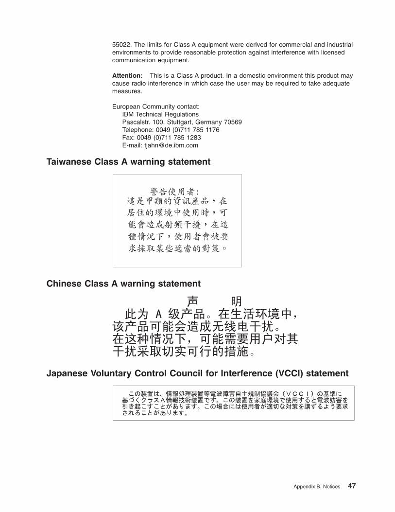
55022. The limits for Class A equipment were derived for commercial and industrial
environments to provide reasonable protection against interference with licensed
communication equipment.
Attention: This is a Class A product. In a domestic environment this product may
cause radio interference in which case the user may be required to take adequate
measures.
European Community contact:
IBM Technical Regulations
Pascalstr. 100, Stuttgart, Germany 70569
Telephone: 0049 (0)711 785 1176
Fax: 0049 (0)711 785 1283
E-mail: [email protected]
Taiwanese Class A warning statement
Chinese Class A warning statement
Japanese Voluntary Control Council for Interference (VCCI) statement
Appendix B. Notices 47
Korean Class A warning statement
48 System Storage EXP3000: Installation, User’s, and Maintenance Guide
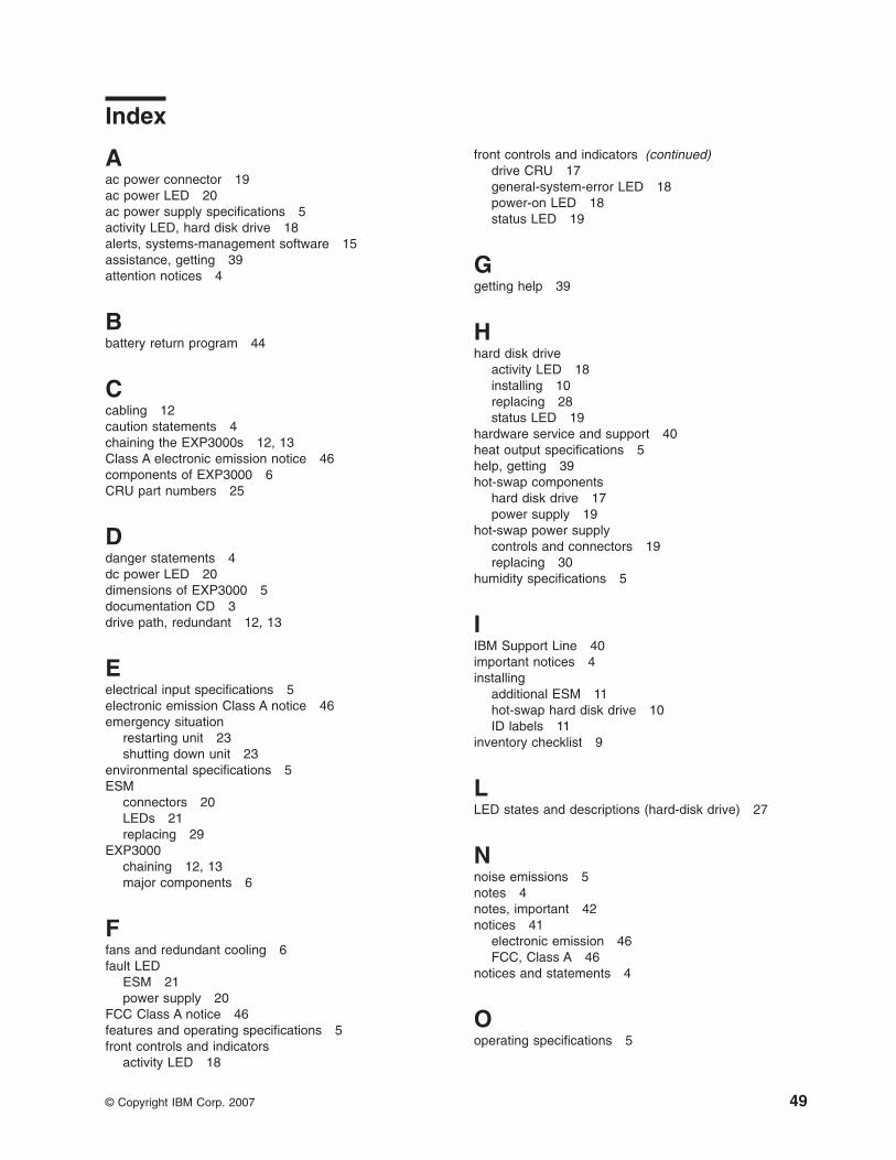
Index
Aac power connector 19
ac power LED 20
ac power supply specifications 5
activity LED, hard disk drive 18
alerts, systems-management software 15
assistance, getting 39
attention notices 4
Bbattery return program 44
Ccabling 12
caution statements 4
chaining the EXP3000s 12, 13
Class A electronic emission notice 46
components of EXP3000 6
CRU part numbers 25
Ddanger statements 4
dc power LED 20
dimensions of EXP3000 5
documentation CD 3
drive path, redundant 12, 13
Eelectrical input specifications 5
electronic emission Class A notice 46
emergency situationrestarting unit 23
shutting down unit 23
environmental specifications 5
ESMconnectors 20
LEDs 21
replacing 29
EXP3000chaining 12, 13
major components 6
Ffans and redundant cooling 6
fault LEDESM 21
power supply 20
FCC Class A notice 46
features and operating specifications 5
front controls and indicatorsactivity LED 18
front controls and indicators (continued)drive CRU 17
general-system-error LED 18
power-on LED 18
status LED 19
Ggetting help 39
Hhard disk drive
activity LED 18
installing 10
replacing 28
status LED 19
hardware service and support 40
heat output specifications 5
help, getting 39
hot-swap componentshard disk drive 17
power supply 19
hot-swap power supplycontrols and connectors 19
replacing 30
humidity specifications 5
IIBM Support Line 40
important notices 4
installingadditional ESM 11
hot-swap hard disk drive 10
ID labels 11
inventory checklist 9
LLED states and descriptions (hard-disk drive) 27
Nnoise emissions 5
notes 4
notes, important 42
notices 41
electronic emission 46
FCC, Class A 46
notices and statements 4
Ooperating specifications 5
© Copyright IBM Corp. 2007 49
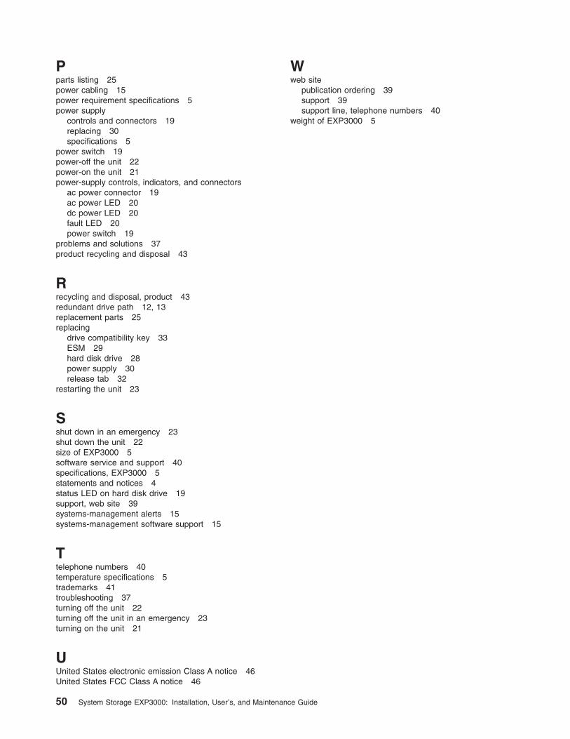
Pparts listing 25
power cabling 15
power requirement specifications 5
power supplycontrols and connectors 19
replacing 30
specifications 5
power switch 19
power-off the unit 22
power-on the unit 21
power-supply controls, indicators, and connectorsac power connector 19
ac power LED 20
dc power LED 20
fault LED 20
power switch 19
problems and solutions 37
product recycling and disposal 43
Rrecycling and disposal, product 43
redundant drive path 12, 13
replacement parts 25
replacingdrive compatibility key 33
ESM 29
hard disk drive 28
power supply 30
release tab 32
restarting the unit 23
Sshut down in an emergency 23
shut down the unit 22
size of EXP3000 5
software service and support 40
specifications, EXP3000 5
statements and notices 4
status LED on hard disk drive 19
support, web site 39
systems-management alerts 15
systems-management software support 15
Ttelephone numbers 40
temperature specifications 5
trademarks 41
troubleshooting 37
turning off the unit 22
turning off the unit in an emergency 23
turning on the unit 21
UUnited States electronic emission Class A notice 46
United States FCC Class A notice 46
Wweb site
publication ordering 39
support 39
support line, telephone numbers 40
weight of EXP3000 5
50 System Storage EXP3000: Installation, User’s, and Maintenance Guide

����
Part Number: 43W7852
Printed in USA
(1P) P/N: 43W7852