Embed Size (px)
Citation preview

INSTALLATION ANDINSTALLATION ANDINSTALLATION ANDINSTALLATION AND
USER MANUALUSER MANUALUSER MANUALUSER MANUALVersion 00 • June 13,2013

EN
VIDEOGRAPH HD – User manual Page 2/24
Index
1 INTRODUCTION ............................................................................................................................................... 3
1.1 COMPLIANCE WITH STANDARDS......................................................................................................................... 3 1.2 POWER SUPPLY................................................................................................................................................... 3 1.3 INSTALLATION PRECAUTIONS............................................................................................................................. 4 1.4 LIABILITY AND OPERATORS................................................................................................................................ 4 1.5 PACKAGING AND ENVIRONMENT ........................................................................................................................ 5 1.6 MARKING AND LABELLING SYMBOLS ................................................................................................................. 5
2 CONTENTS ......................................................................................................................................................... 6
3 INSTALLATION................................................................................................................................................. 7
3.1 PRECAUTIONS..................................................................................................................................................... 7 3.2 EQUIPMENT INSTALLATION ................................................................................................................................ 8 3.3 SOFTWARE INSTALLATION ................................................................................................................................. 9 3.4 CONFIGURATION IN THE IMAGING SOFTWARE.................................................................................................. 10 3.5 SHARING THE SENSOR AND BOX BETWEEN DIFFERENT WORKSTATIONS ........................................................... 11
4 USE...................................................................................................................................................................... 12
4.1 PRECAUTIONS................................................................................................................................................... 12 4.2 SENSOR PRINCIPLES.......................................................................................................................................... 12 4.3 USE OF THE XIO STANDALONE SOFTWARE..................................................................................................... 13 4.4 ACQUISITION OF AN IMAGE.............................................................................................................................. 15 4.5 EXPOSURE TIMES.............................................................................................................................................. 16
5 HYGIENE AND MAINTENANCE ................................................................................................................. 17
5.1 HYGIENE AND DISINFECTION............................................................................................................................ 17 5.2 RECOMMENDED CLEANING AND DECONTAMINATION PROCEDURE................................................................... 18 5.3 MAINTENANCE ................................................................................................................................................. 18
6 TROUBLESHOOTING .................................................................................................................................... 19
6.1 GENERAL .........................................................................................................................................................19 6.2 IMAGE QUALITY ............................................................................................................................................... 20
7 SPECIFICATIONS ...........................................................................................................................................21
7.1 GENERAL SPECIFICATIONS............................................................................................................................... 21 7.2 REGULATORY DECLARATIONS......................................................................................................................... 22 The manufacturer, OWANDY, reserves the right to make modifications to its products or to their specifications in order to improve the performance, quality, or ease of production.Specifications of products or accessories may be modified without prior notice. No part of this manual may be reproduced without the prior consent of the manufacturer, Owandy. Language of original document:French.
Year CE marking assigned: 2013
OWANDY Le Coruscant - 2, rue des Vieilles Vignes
77183 Croissy-Beaubourg FRANCE
Telephone : +33 1.64.11.18.18 Fax : +33 1.64.11.18.10

EN
VIDEOGRAPH HD – User manual Page 3/24
1 Introduction You have just received your Videograph HD new generation digital intra-oral radiology kit, with direct USB connection. We thank you for the confidence you have in us and hope that this product will give you entire satisfaction. We recommend you to read this manual thoroughly before installation; following the guidelines for installation and usage described in it will exclude risks to the patient and the care team.Please keep it close to your equipment so you can refer to it at a later date. Your sensor uses an X-ray sensitive electronic detector (the flat part at the bottom of the sensor) that replaces the conventional film used for the acquisition of radiological intra-oral images.The X-rays are automatically detected by the sensor which triggers image acquisition.The acquired image is displayed almost instantaneously on the screen of the computer to which the sensor is connected.These digital images can then be manipulated, analysed, saved as files or printed. The development process of conventional films is thus completely eliminated as well as the possible influences on image quality; such as the type and age of the chemical product, the temperature of the baths or the development time. The sensor is available in two sizes; depending on the kit you have ordered you received a size 1, a size 2 sensor or both:
• The size 1 sensor allows you to acquire the majority of intra-oral images (peri-apical and retro-coronary) both vertically and horizontally.
• The size 2 sensor furthermore allows you to easily acquire horizontal “bitewing” images.
The instructions and information in this manual refer to both sensor sizes, unless specifically stated.The size of the sensor is marked on the sensor itself.
1.1 Compliance with standards
The Videograph HD kit is class IIA equipment within the meaning of the European Directive 93/42/CEE concerning CE markings. The Videograph HD kit complies with the EN/IEC60601-1 medical standard. Under certain conditions (see chap. 1.3 “Installation precautions”) it is necessary that the other components of the system that are possibly connected (computer and optional peripherals) are also compliant to standard IEC950 (EN60950) and that the installation complies with the EN/IEC60601-1 standard. The intra-oral sensor is contained within a hermetic and sealed case (resistant to immersion). There is no physical or electrical connection between the Videograph HD kit and the X-ray generator.
1.2 Power supply
The power to the Videograph HD box is provided directly by the power supply of the USB cable connecting it to the computer.

EN
VIDEOGRAPH HD – User manual Page 4/24
1.3 Installation precautions
As the intra-oral sensor is situated inside the patient environment (less than 1,5m / 4.9ft from the patient), your computer must necessarily comply with standard EN/IEC60601-1, or your installation including the computer must have been rendered compliant with standard EN/IEC60601-1-1. You can connect the sensor to your computer without additional precautions once your complete installation is compliant with standard EN/IEC60601-1.
If the computer is not situated in the patient environment and is not compliant with standard EN/IEC60601-1, it is necessary to place the sensor in non-conductive packaging.
The Videograph HD sensor is an electrical medical device requiring special precautions regarding electromagnetic compatibility. Please observe the recommendations in this manual during the commissioning and use of the equipment. The use of cables or accessories other than those specified in this manual can cause an increase in the emissions or a reduction in the immunity of the Videograph HD sensor.
1.4 Liability and operators
Installer :the installation of the kit requires computer skills relating to both equipment and software.Follow the recommendations and guidelines of the installation chapter to install the equipment and software. User:the kit must be used by a dental practitioner.
The sensor should never be opened by the user.Only the manufacturer is authorised to open and make repairs to the sensor.Return the equipment to the distributor in case of malfunction and/or if the documentation you possess does not contain the necessary information for the (authorised) maintenance of the malfunctioning equipment. Any modification of the Videograph HD device is forbidden. All repairs of this same device can only be performed by authorised personnel.
The manufacturer will not be liable if:
• Interventions or repairs have been made by persons without the authorization of the manufacturer or distributor and are not part of accepted interventions.
• The equipment is used with an installation that is not compliant with the applicable standards and decrees - in particular when not compliant with the EN/IEC60601-1-1 standard relating to the security rules for electro medical systems.Make sure the installation of the equipment is compliant with the applicable regulations.
• Used in ways other than those mentioned specifically in this manual (use of the kit in normal conditions of use and in compliance with its intended purpose).
EN
VIDEOGRAPH HD – User manual Page 5/24
1.5 Packaging and environment
Transport, storage and environment:the kit is supplied in protective packaging (protection against physical impacts and antistatic packaging).It must be stored under the following conditions: Ambient temperature: -10°C to +70°C / 14°F to 158°F Relative humidity: <95% without condensation Atmospheric pressure: 500hPa to 1060hPa Operation:in compliance with the international safety standard EN/IEC601-1 (section 2), the kit has been designed for normal use under the following conditions: Ambient temperature: +10°C to +40°C / 50°F to 104°F Relative humidity: 30% to 75% Atmospheric pressure: 700hPa to 1060hPa Equipment packaging for return to distributor :should a return to the distributor be necessary, make sure to package the sensor and box kit in its original packaging after having cleaned it thoroughly. Documentation loss:all kits are shipped with its documentation.Please contact your distributor for a replacement manual if this documentation is lost.
1.6 Marking and labelling symbols
These symbols are used on the product labels and inform you about the compliance with standards and the technical specifications of the component.
Direct current.
Type B equipment, EN/IEC 60-601-1, annexes I and II.
The CE marking certifies that this product complies with European directive 93/42 CEE.
Important information:follow the instructions printed in this manual.
Sensor waterproofness standard, EN/CEI 60529 regulation.
Only the part of the sensor put in mouth, complies with this standard.
Storage condition: temperature limitations.
Storage condition: relative humidity limitations
Storage condition: Atmospheric pressure limitations.
Equipment subject to a selective collection in accordance with Directive 2002/96/EC on waste electrical and electronic equipment (WEEE) and with Decree 2005-829 of the 20th July 2005 regarding the composition of electrical and electronic equipment and the elimination of waste coming from this equipment.

EN
VIDEOGRAPH HD – User manual Page 6/24
2 Contents Your Videograph HD kit consists of the following elements (illustrations may vary from items supplied):
An Videograph HD sensor - size 1 or size 2 (cable of 3m / 9.9 feet)
1 self-adhesive sensor wall support
Positioner kit
(available for size 1 sensor as default)
A bag of disposable single-use hygienic protective sleeves
(compatible with size 1 and 2 sensors)
A CD-ROM with the installation files of the sensor
A CD ROM with Quickvision Villa package (Imaging software and sensor driver)
A CD-ROM with user manuals
A manual A packaging checklist

EN
VIDEOGRAPH HD – User manual Page 7/24
3 Installation
3.1 Precautions
The kit must be handled with care, minimise the twisting, pulling and bending of the attachment cable.Do not step or roll on the cable.Do not pull on the cable itself but on the connection plug to disconnect the USB cable. To avoid interferences in the image, do not use the system close to strong magnetic fields and avoid proximity to electrostatic emission sources. Read paragraph “Installation precautions” to ensure the installation complies with the standards
Install your imaging software before the installation of the kit, its drivers and O.S.P. tools and the installation files of the sensor.
3.1.1 Recommended minimal configuration Any computer configuration that does not comply with the minimal recommended configuration can prevent the starting or proper functioning of the sensor kit.Verify the specifications of the computer(s) before the installation.
Operating system Windows XP SP2, Vista or Seven (32 and 64 bits)
Computer Motherboard USB port
Compliant CE-IEC950 Intel 1.4GHz chipset and processor USB 2.0 High-Speed
Graphics card Monitor
64MB High resolution 1024x768 (15inch)
RAM memory Hard disk
256MB 10GB
CD-ROM drive Backup system
24x External/removable disk, Zip or Jaz system, CD-ROM/DVD…
Printer Keyboard and mouse
Laser, inkjet, thermal
At acquisition workstation Videograph HD kit with appropriate drivers Imaging software X-ray generator with electronic timer
If your computer does not possess USB 2.0 ports, these can be added as PCI/PCI express cards (for desktop computers) or PCMCIA cards (for laptops).If the USB ports do not provide enough current, please use a powered hub (with its own power supply).The PCMCIA cards need to be powered by an external power supply or connected to a powered hub if they do not provide enough current.Please contact your IT specialist for further information.
3.1.2 Setup guidelines The computer and the screen with which the sensor and the box are used should preferably be situated close to the chair, within the field of vision of the practitioner, to allow for immediate use.Provide visual access for the patient to be able to share the radiological information with him/her. The screen must be placed so as to avoid any reflections or direct overhead illuminations that could be detrimental to the visualization of the radiological images.It must be set up (contrast and brightness) to display as many grey levels as possible in the image.

EN
VIDEOGRAPH HD – User manual Page 8/24
The X-ray generator has a great influence on the quality of the acquired images.The kit is compatible with any kind of generator, be it high-frequency or conventional.The generator must be equipped with an electronic timer (allowing for very short exposure times) and must emit a dose sufficient for the acquisition of a good image (with enough grey levels).Make sure that your generator is not worn as the dose emitted will be insufficient and could influence the quality of the acquired image.The energy emitted by a generator diminishes over time; when in doubt have your generator checked by a qualified technician.Make sure he had of the generator is stable, any movement of the head will induce movement blur in the acquired image.
3.2 Equipment installation
3.2.1 Connection
The Videograph HD sensor is fitted directly to a cable equipped with a USB connector linking it directly to the computer. If the distance between the sensor and the computer is greater than the 3m / 9.8ft of USB cable, it is possible to add USB cables by using a USB distributor (“hub”) connected to an external mains power supply, between each cable.
Connection without hub
Connection with powered hub
Connection with power supplied hub
Make sure the USB port of the computer is preferably a USB 2.0 port.Only use USB 2.0 cables and hubs with a USB 2.0 port and make sure that the hub has its own external power supply (do not use self-powered hubs, drawing the power from the USB cable).Each USB cable should not be longer than 3m / 9.8ft.The kit is compatible with USB 1.1 ports but with reduced image transmission speed.
The USB cable can be connected / disconnected without the need to power down the computer. Check that the sensor is correctly connected:if the sensor toolbar turns green after removing the sensor from its support, it is powered correctly.
3.2.2 Sensor support The sensor can be placed on its self-adhesive support supplied with the kit.The support is compatible with sensors of size 1 or size 2. This support can be fixed on any type of flat surface:worktop or a part of the chair.The sensor will then be inserted into the fork of the support taking care not to impede the cable.
Do not mount the wall support upside-down or horizontally, the sensor could fall on the ground and be damaged.

EN
VIDEOGRAPH HD – User manual Page 9/24
3.3 Software installation
Install the imaging software and check its proper functioning before installing the equipment and its drivers.Refer to the software manual for the installation instructions.
You need administrator rights for the installation and use of the software and equipment.Please contact your IT specialist to create a suitable user account.
3.3.1 Installation of the drivers The Videograph HD drivers are only compatible with the Windows XP (service pack 2 or higher), Windows Vista and Windows Seven operating systems – 32 and 64 bits.
Insert the Quickvision Villa CD-ROM in the CD-ROM-drive.The interface will launch automatically and will guide you through the different installation steps.Refer to the Windows help if the CD-Rom does not launch automatically.
1. Connect the USB cable to the connection box and the USB 2.0 port of the computer. Windows will automatically detect your box.
2. Dismiss the automatic installation wizard “Add hardware wizard” of Windows.
3. From the Quickvision installation menu select “Drivers” then
“Install intraoral sensor (USB)”. 4. Select the desired language then press the button “Next”. The
installation wizard for OSP – CMOS XRAYS BOX will be launched.
5. Press the button “Next” then “Install”, then complete the setup
by following the wizard. At the end of the installation the following messages will be shown:
6. From the Quickvision installation menu press the button “End” then “Exit”:

EN
VIDEOGRAPH HD – User manual Page 10/24
3.3.2 Sensor installation files Each kit is provided with a sensor installation CD-ROM of its own; the serial number of the sensor is written on the CD-ROM and on the connection box.You can therefore not use the same CD-ROM to install several sensors; each sensor requires its own CD-ROM.
Before installing the sensor installation files, make sure that:
• The drivers of the kit are installed. • The imaging software is not started.
Insert the sensor installation CD-ROM, a window appears and the files are copied to the hard disk.Close the window after the files have been copied by pushing any key of the keyboard when asked for
3.4 Configuration in the imaging software
To be able to use your kit with the QuickVision imaging software you must configure your equipment.
1. Start the imaging software (double-click on the desktop icon or use the link in Start / Programs / QuickVision). Configuration in case of QuickVision version 3
2. Click on the “Configuration” button in the main screen. 3. Select “Videograph Intra-Oral sensor” option in the window that
appears.
4. Click on “Set up” at the right of the menu to access to configuration menu (see the window below)
5. Click on “OK” to confirm your choice.
6. Then click on the “Save” button QuickVision 3 to validate the settings.
The use of the kit is identical to the use of the XIO StandAlone software described below.
In the configuration window: ◄ Check the “USB” type model, VIDEOGRAPH HD. ◄ Set the activation time of the box (default 5min). ◄ Set the inlay and size of the date & time and exposure parameters in the acquired image. ◄ Select the image treatment (*). ◄ Configure the QuickVision Villa software (**).
(*) When the “Film alike” option is activated, the contrast depends on the exposure time. Adjust the X-ray dose on the generator to obtain a good image. In both cases, the exposure bar (blue/green/red) helps to find the correct exposure of the images. (**) This option appears only when the sensor is used from certain Owandy software programs; it allows the change of the sharpness setting or the high resolution for each acquired image.

EN
VIDEOGRAPH HD – User manual Page 11/24
3.5 Sharing the sensor and box between different workstations
Sharing the sensor allows you to use one or more sensors in turn in a practice with multiple chairs.It is recommended to link the different workstations in a network to allow for the central storage and sharing of the images. A USB port must be plugged into each workstation to allow for an easy connection of the box.Windows will automatically recognise the equipment when it is connected and it will be available immediately for image acquisition. To enable the sharing of a kit between different workstations, it is necessary to first install the imaging software for the acquisition of the images, the drivers and sensor installation files on all the computers with which yourVideograph HD will be used.

EN
VIDEOGRAPH HD – User manual Page 12/24
4 Use
4.1 Precautions
Make sure the sensitive surface (the flat surface) of the sensor is directed towards the X-ray generator.The active surface of the sensor is marked by a frame.The back of the sensor (rounded) does not react to X-rays and does not produce an image on-screen.
The kit must be manipulated with care, minimising the twisting, pulling and bending of the attachment cable.Do not step or roll on the cable.Be careful not to pull on the cable when removing the hygienic protective sheaths.
Do not pull on the cable itself, but on the plug to disconnect the USB cable. Even though the sensor is resistant to impacts, it is strongly recommended to not let it fall on the floor.If a physical impact should exceptionally happen, contact your distributor and do not try to intervene yourself.
Do not ask the patient to bite on the sensor or cable. Use of a mobile phone or an RF communications device near the Videograph HD sensor may affect the sensor.
4.2 Sensor principles
4.2.1 Sensor The sensor’s sensitive area is delimited by a horizontal line; the area below this line is not sensitive to X-rays.When the sensor is placed in the mouth it is necessary to check that this area is turned towards the radiation source and that the whole sensitive area is irradiated.
Active surface Sensor’s rear shell:inactive surface
4.2.2 Sensor activation The sensor automatically puts itself on standby after a period which can be configured in the configuration window (see “3.4 Configuration in the imaging software” - the default period is 5 minutes).The sensor’s toolbar is then in its red state. To activate your sensor it is enough to enable it using the XIO StandAlone software
EN
VIDEOGRAPH HD – User manual Page 13/24
4.3 Use of the VILLA S.M. XIO StandAlone software
4.3.1 Modes of operation The sensor kit can function in two ways:
• Through the Twain protocol (for scanners):to use this mode select “Villa Intra Oral X-rays…” in the TWAIN acquisition option of your imaging software.Subsequently start the TWAIN acquisition; the interface is identical to that of the independent mode described below.
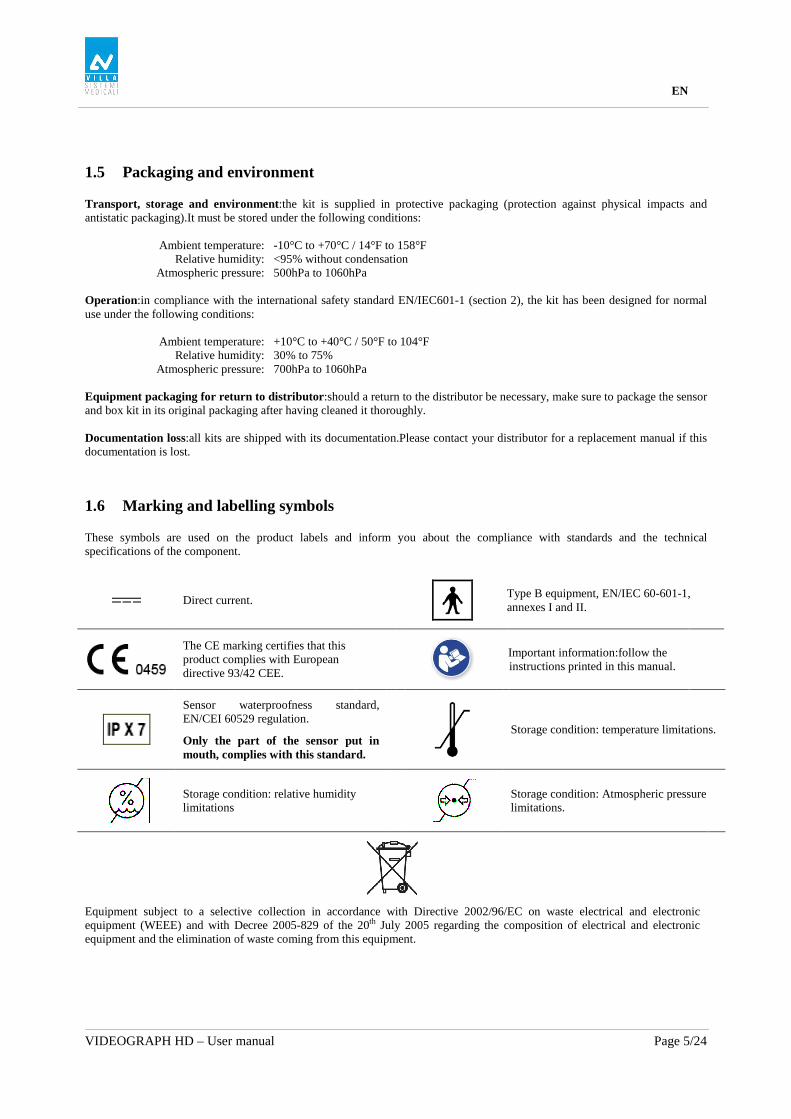
• In independent mode:the independent software program can be started with the “SENSOR” icon (on the Windows desktop) or by starting the software program. This memory resident software package allows the use of the sensor outside any software program. If an image is acquired without a program ready to receive it, the resident program will display the image on-screen for a few seconds and save it in the “C:\Program Files\VILLA S.M.\OSP - XRAYS BOX STANDALONE\StandAlone\Data” directory on the hard disk.A sensor icon appears in the Windows taskbar, next to the clock.The colour of the icon indicates the state of the sensor:
Red:sensor inactive
Yellow:sensor initialising
Green:sensor ready for acquisition
4.3.2 Sensor toolbar It is possible to display the sensor toolbar by clicking with the right mouse button on the sensor icon in the taskbar.The colour of the sensor toolbar indicates the state of the sensor:
Red:sensor inactive
Yellow:sensor initialising
Green:sensor ready for acquisition
Options of the sensor toolbar:
◄ Orientation of the sensor (vertical or horizontal), double-click the icon to change the orientation of the sensor.
◄ Activate/deactivate the sensor. ◄ Size of the selected sensor. ◄ Iconize the toolbar in the taskbar.
The sensor automatically switches to standby mode after a few minutes of not being used; the sensor toolbar turns red. Check that the sensor toolbar is displayed in green before each acquisition.

EN
VIDEOGRAPH HD – User manual Page 14/24
4.3.3 Configuration menu A right-click on the sensor icon in the taskbar or on the sensor toolbar displays the configuration menu:
X-ray sensor Displays the sensor toolbar.
Start when Windows starts Once checked, the StandAlone program will be launched each time your computer is started.
Configuration Displays the configuration menu (see “3.4Configuration in the imaging software”).
Display new images for Adjusts the display time of the image.
Remaining images Allows you to browse through the images waiting to be transferred.If no image is acquired this option is not displayed.
Exit Closes the resident software program.Warning :the acquisition will no longer be available until the resident program is restarted.
4.3.4 Image transfer interface
Options of the image transfer interface:
Image display When an image is selected, it is displayed on a blue background.
“Load” button Transfers the selected image to the software program.
“Cancel” button Cancels the image selection and starts the toolbar for a new acquisition (only when in a software program).
“Preview” button Displays the selected image full-screen.
“Email” button Opens a blank email and attaches the image in a zip file.
“Delete” button Deletes the selected image.
“Delete on load” option Deletes the selected image from the list after it has been transferred to a software program.

EN
VIDEOGRAPH HD – User manual Page 15/24
4.4 Acquisition of an image
4.4.1 Acquisition procedure The image acquisition goes through several steps:
1. Before being able to acquire an image with the sensor, you need to start the computer to which it is connected and start the imaging software.Check that the sensor toolbar or the sensor icon in the task bar is green.
2. Program the different parameters (exposure time, etc.) on the X-ray generator (see “4.5 Exposure times” for more
information).
3. Cover the sensor with a hygienic protective sheath making sure to cover a sufficient length of cable.
4. A set of positioners is provided with the kit to place the sensor in the different parts of the mouth; their use is recommended to ensure the sensor is positioned perpendicularly to the X-ray beam. The sensor can also be positioned manually, maintained by the patient as with conventional film.This can be necessary for children with a small oral cavity.Position the sensor in the mouth, behind the tooth of which you want to acquire an image.If you do not use a positioner, a cotton roll can be helpful to position the sensor parallel to the tooth. Turn the sensitive surface of the sensor (the flat surface) towards the generator; if it is facing the other way, the sensor will not be able to acquire images.
5. Position the generator so as to cover the whole sensitive area of the sensor.The paralleling technique is strongly
recommended and the use of positioners allows you to correctly place the generator thanks to the aiming ring.
6. Activate the generator.The sensor toolbar turns yellow to indicate the treatment and transmission of the acquired image.Once the image treated, it appears in the imaging software and the sensor toolbar turns green allowing a new acquisition.
4.4.2 Imaging software functions An exposure percentage is displayed in the acquired image:
• 0 to 80% - under-exposed image, the X-ray dose is too low; increase the X-ray dose on the generator. • 80 to 120% - correctly exposed image • 120 to 200% - over-exposed image, the X-ray dose is too high; reduce the X-ray dose on the generator.
When the image is displayed in the imaging software, a coloured bar appears in the top part of the image, this is the exposure bar.This function is available only to users of the imaging software.
The white cursor displayed in this bar indicates the exposure level of the image:
• If the cursor is in the green, the image is correctly exposed. • If the cursor is in the red, the image is over-exposed; reduce the exposure time on the generator. • If the cursor is in the blue, the image is under-exposed; increase the exposure time on the generator.

EN
VIDEOGRAPH HD – User manual Page 16/24
4.5 Exposure times
Recommended exposure times in seconds for the Villa Sistemi Medicali X-ray generators:
Description Villa SM Endograph DC Villa SM Endos AC
Current / Voltage 7mA / 65KV 8mA / 70KV
Lower incisor / canine 0.06 – 0.09 0.04 – 0.08
Lower premolar 0.06 – 0.10 0.06 – 0.10
Lower molar 0.07 – 0.11 0.07 – 0.12
Upper incisor / canine 0.08 – 0.10 0.06 – 0.10
Upper premolar 0.08 – 0.11 0.08 – 0.12
Upper molar 0.11 – 0.16 0.10 – 0.14
Reference conditions: • Adult patient, young man or woman of average size • Distance focal spot to sensor 250mm / 9.8inch • Total (inherent) filtration equivalent to 2mm / 0.08inch Al
The values indicated in the table above can vary from one generator to another.It is the responsibility of each user to calibrate his/her doses before use. If an image is over or under-exposed, it can be corrected afterwards with the imaging software (contrast, brightness, etc.) to improve its visualisation. The table below allows you to note the exposure times specific to your generator:
Description Adult Child
Lower incisor / canine
Lower premolar
Lower molar
Upper incisor / canine
Upper premolar
Upper molar

EN
VIDEOGRAPH HD – User manual Page 17/24
5 Hygiene and maintenance
5.1 Hygiene and disinfection
5.1.1 USB Connector The connector does not require any particular maintenance, it should be cleaned using a cloth and non-abrasive detergents.
5.1.2 Sensor To avoid cross-contamination between patients during use, it is necessary to protect the sensor with hygienic single-use protective sheaths (FDA cleared for the USA, CE marked for Europe).Some hygienic protective sheaths suited for your region are provided with each system. Before each use on a patient, the used sheath should be thrown away and the sensor disinfected applying a high level disinfection procedure (see “5.2 Recommended cleaning and decontamination procedure”). A new protective sheath is applied to the sensor for each new patient.We recommend the disposal of the hygienic protective sheaths with the biologically hazardous waste of your practice. Validated protections for North America: BANTA HEALTHCARE or TIDI PRODUCTS X-ray sensor sheaths, STERI-SHIELD PRODUCTS RS barriers.
Do not pull on the cable when removing the used protective sheath.
5.1.3 Cables The cable can be cleaned with caution by using a disinfecting wipe.Hold the sensor with one hand and, with the other hand, apply a disinfecting wipe from the side of the sensor along the first 20cm / 8inch of the cable without pulling on the cable; subsequently clean the remainder of the cable in segments of 20-30cm / 8-12inch with as little pinching of the cable as possible, the wipe should slide without applying force.
5.1.4 Positioners The positioners provided with the system should be covered by the hygienic protective sheath together with the sensor.
Do not pull on the cable when removing the sensor from the positioner.
They should be cleaned and disinfected according to the same procedure as for the sensor (see “5.2 Recommended cleaning and decontamination”). They can be sterilised, either in an autoclave (classic steam-sterilizer, distilled water, 134°C / 273°F, 3bar, 4min) or using cold sterilisation (see product instructions).They withstand a maximal temperature of 145°C / 293°F. A defective positioner can be thrown away with the regular waste.

EN
VIDEOGRAPH HD – User manual Page 18/24
5.2 Recommended cleaning and decontamination procedure
Remove the hygienic protective sheath (dispose of it appropriately with the contaminated waste).Vigorously wipe down the sensor to remove any visible residues.If necessary rinse with copious amounts of water.Then place the sensor in the disinfecting agent.
Only immerse the sensor and the head of the positioner or sensor connection cable in the disinfectant for 15min, never immerse the connector on the box side of the positioner or sensor connection cable in the liquid.
During the immersion, brush the submerged parts with a soft brush.Then rinse thoroughly the sensor and the positioner or the sensor connection cable with copious amounts of fresh water.
Do not put the sensor in a sterilizer or an autoclave, the high temperature and excessive high pressure will seriously damage the electronics of the sensor and connectors. Do not clean the sensor with inappropriate instruments (knife…).
If the sensor, positioner or sensor connection cable are not being used immediately upon rinsing, as in the case of allowing them to air-dry overnight at the end of a working day, they should be rinsed with sterile water. When the sensor, positioner or sensor connection cable are not being used, to protect them from any damage, it is recommended to store them in their box or to hang them in the sensor wall support. Even when using protective sheaths, the sensor should be disinfected regularly.Immerse the sensor in cold sterilisation fluid in accordance with the instructions of the manufacturer after having cleaned it from all residues.Never leave the sensor immersed for longer than necessary.
5.2.1 Recommended decontaminating product for North-America The sensor being sealed watertight and to minimize the potential for device-associated infections, the sensor and the part of the positioner or sensor connection cable inserted in the mouth shall be disinfected with an FDA-cleared high level disinfection agent following the instructions of the manufacturer for use, storage, handling and warning. The following disinfectant agent has been validated with the sensor:CIDEX OPA solution (0.55% Ortho-phthalaldehyde solution).The maximum soaking period is 24 hours.
5.2.2 Recommended decontaminating products outside North-America The following disinfectants are compatible with the sensor and the part of the positioner or sensor connection cable that is inserted in the mouth:
• 2% Sodium Hypochlorite (maximum immersion time of 24 hours) • Ethyl alcohol (maximum immersion time of 24 hours) • Quaternary ammonium
5.3 Maintenance
5.3.1 Computer data-protection Your patient and image database must be backed-up regularly to be able to recuperate them if needed (in case of hard disk or computer problems).Ask the advice of your IT specialist with regard to the backup system that is best suited to your computer configuration (external or removable hard disk, Zip or Jaz system, CD-ROM or DVD writer, etc.).Test and store the copies in a safe place.
EN
VIDEOGRAPH HD – User manual Page 19/24
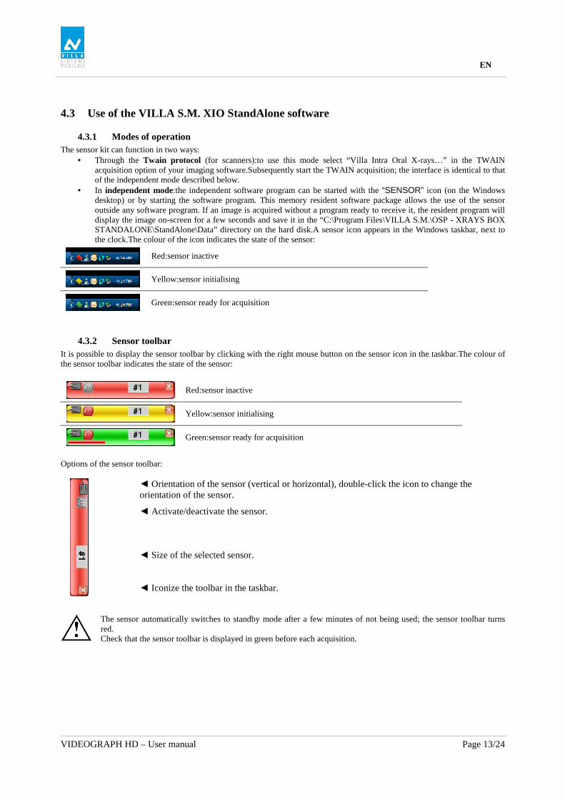
6 Troubleshooting If an error occurs during operation, check the different items in this troubleshooting guide.If you cannot resolve your problem please contact your distributor.
6.1 General
Symptom Cause / Solution
The kit does not power up or it does not acquire images.
• Check that the active surface of the sensor is directed towards the X-ray generator and is positioned correctly in the field of the X-ray beam.
• Check that the kit is correctly configured in the imaging software and that the drivers are correctly installed.
• Check the connection between the sensor and the PC, and ensure that the PC is powered externally.
• Check that the generator is emitting X-rays (with another sensor or with conventional film).
No image appears on the screen. • An error has occurred during acquisition, disconnect the cable and wait a few seconds before reconnecting it.
• Check that the outer sheath of the cable connection from the sensor does not show any signs of tearing.
The sensor is slightly warm. This is normal. The temperature of the sensor can exceed 12°C (54°F) when the kit is activated for a prolonged period (e.g. when taking many consecutive images) and has no bearing on the functioning of the kit.
• Reduce the standby time in the configuration screen.

EN
VIDEOGRAPH HD – User manual Page 20/24
6.2 Image quality
Symptom Cause / Solution
The images are cut off, e.g.:
The sensor is badly positioned with regard to the X-ray beam.
• Reposition the sensor, making sure it is well within the field of the X-ray beam.
• Use the positioners provided with the sensor for optimal positioning.
The images are too light or contain noise, e.g.:
211 1
Film alike mode Auto contrast mode
• The image is under-exposed, the X-ray dose is too low; increase the X-ray dose on the generator.The percentage that is displayed in the image indicate the exposure level:
o 0 to 80% - under-exposed image o 80 to 120% - correctly exposed image o 120 to 200% - over-exposed image
• Check the dose emitted by the X-ray generator, due to age the dose can be insufficient.Have the generator checked by a technician when in doubt.
• The generator is positioned too far from the patient with regard to the selected dose.
• Check the parameters of your monitor (contrast and brightness) and avoid reflections on the screen.
The images are too dark, e.g.:
• The image is over-exposed, the X-ray dose is too high; reduce the X-ray dose on the generator.The percentage that is displayed in the image indicate the exposure level:
o 0 to 80% - under-exposed image o 80 to 120% - correctly exposed image o 120 to 200% - over-exposed image
• Check the parameters of your monitor (contrast and brightness) and avoid reflections on the screen.
Grey levels seem to be missing in the image (flat areas of grey appear).
• Check the quality and parameters of the monitor.
• Check the connection of the cable of the screen at the side of the graphics card and the monitor.
• Check the screen configuration under Windows (screen configuration panel, it must display colours in at least 24bits.
The image is blurred. Re-acquire the image:
• The patient has moved during the exposure.
• The generator head was not stabilised and has moved.

EN
VIDEOGRAPH HD – User manual Page 21/24
7 Specifications
7.1 General specifications
Videograph HD Sensor - Size 1
External dimensions size 1 sensor 38.6 x 24.7 x 5.2mm / 1.6 x 1.0 x 0.2inch
CMOS matrix size 1 sensor (cut corners) • Sensitive area in size
• Sensitive area in pixels • Pixel dimensions
30 x 20mm (600mm2) / 1.2 x 0.8inch (1.0inch2) 1500 x 1000pixels 20 x 20µm
Videograph HD Sensor - Size 2
External dimensions size 2 sensor 43.2 x 30.8 x 5.2mm / 1.7 x 1.2 x 0.2inch
CMOS matrix size 2 sensor (cut corners) • Sensitive area in size
• Sensitive area in pixels • Pixel dimensions
34 x 26mm (900mm2) / 1.3 x 1.0inch (1.3inch2) 1700 x 1300pixels 20 x 20µm
Technical specifications (size 1 and 2 sensors)
Length sensor cable) 3m / 9.9ft
Grey levels 14bits (16384 grey levels)
Connection USB standard: USB 2.0 High-Speed (480Mbit/s) and USB 3.0
Consumption kit 0.5VA under 5V (USB port)
Input voltage sensor Input current sensor
0.15A Max
Operating temperature +10°C to +40°C / 50°F to 104°F
Lifespan CMOS Min.100,000 cycles
Standards
Conformity to standards NF EN/IEC60601-1
NF EN/IEC60601-1-2

EN
VIDEOGRAPH HD – User manual Page 22/24
7.2 Regulatory Declarations
Table 1 Manufacturer’s instructions and declaration – electromagnetic emissions
The VIDEOGRAPH HD model is designed for use in the electromagnetic environment specified below.TheVIDEOGRAPH HD customer or user must ensure that it is used in such an environment.
Emissions test Compliance Electromagnetic environment - instructions RF emissions CISPR 11
Group 1 The VIDEOGRAPH HD model only uses RF energy for its internal functions. Consequently, its RF emissions are very low and are not capable of causing interference in nearby electronic equipment.
RF emissions CISPR 11
Class B
Harmonic emissions IEC 61000-3-2
Not applicable
Voltage fluctuations/ flicker IEC 61000-3-3
Not applicable
The VIDEOGRAPH HD model is suitable for use in all premises, including domestic premises and those directly connected to the low voltage public electricity supply network supplying buildings for domestic use.
Table 2
Manufacturer’s instructions and declaration – electromagnetic immunity The VIDEOGRAPH HD model is designed for use in the electromagnetic environment specified below.TheVIDEOGRAPH HD customer or user must ensure that it is used in such an environment. Immunity test IEC 60601
Test level Compliance level Electromagnetic environment - instructions
Electrostatic discharge (ESD) IEC 61000-4-2
± 6 kV at contact ± 8 kV in the air
± 6 kV at contact ± 8 kV in the air
Floors must be of wood, concrete or ceramic tiles. If floors are covered with synthetic materials, the relative humidity must be at least 30%.
Rapid transients in bursts IEC 61000-4-4
± 2 kV for electricity supply lines ± 1 kV for input/output lines
Not applicable The quality of the electricity supply network must be that of a typical commercial or hospital environment.
Transient overvoltage IEC 61000-4-5
± 1 kV between phases ± 2 kV between phase and earth
Not applicable The quality of the electricity supply network must be that of a typical commercial or hospital environment.
Voltage dips, brief power cuts and variations in voltage on electricity supply input lines IEC 61000-4-11
<5 % UT (>95 % dip in UT) for 0.5 cycle 40 % UT (60 % dip in UT) for 5 cycles 70 % UT (30 % dip in UT) for 25 cycles <5 % UT (>95 % dip in UT) for 5s
Not applicable The quality of the electricity supply network must be that of a typical commercial or hospital environment. If the VIDEOGRAPH HD user requires continuous operation during power cuts in the electricity supply network, it is recommended to supply VIDEOGRAPH HD from an uninterruptible energy supply or a battery.
Magnetic field at the frequency of the electricity network (50/60 Hz) IEC 61000-4-8
3 A/m 3 A/m Magnetic fields at the frequency of the electricity network must have the same characteristic levels as a representative place located in a typical commercial or hospital environment.
NOTE:UT is the voltage of the alternative network before application of the test level.

EN
VIDEOGRAPH HD – User manual Page 23/24
Table 3
Manufacturer’s instructions and declaration – electromagnetic immunity The VIDEOGRAPH HD model is designed for use in the electromagnetic environment specified below.TheVIDEOGRAPH HD customer or user must ensure that it is used in such an environment. Immunity test IEC 60601
Test level Compliance Level
Electromagnetic environment - instructions
Conducted RF interference IEC 61000-4-6 Radiated RF interference IEC 61000-4-3
3 Veff from 150 kHz to 80 MHz 3 V/m from 80 MHz to 2.5 GHz
3 V 3 V/m
Portable and mobile RF communications equipment must not be used nearer to any part of VIDEOGRAPH HD, including the cables, than the recommended separation distance, calculated on the basis of the equation applicable to the frequency of the transmitter. Recommended separation distance d=1.16√P d=1.16√P from 80 MHz to 800 MHz d=2.33√P from 800MHz to 2.5 GHz where P is the transmitter’s maximum output power rating in watts (W), according to the transmitter’s manufacturer and d is the recommended separation distance in metres (m). The field intensities of fixed RF transmitters, determined by an on-site electromagnetic investigationa, must be below the compliance level, in each frequency rangeb. Interference can occur near a device marked with the following symbol:
NOTE 1:At 80 MHz and 800 MHz, the higher frequency range applies. NOTE 2:These directives may not apply in all situations.Electromagnetic propagation is affected by absorption and reflection by structures, objects and people. a:The field intensities of fixed transmitters, like base stations for radiotelephones (cellular/cordless) and mobile land radios, amateur radio, AM and FM radio broadcasting and TV broadcasting, cannot be theoretically foreseen with exactitude.In order to assess the electromagnetic environment produced by fixed RF transmitters, an on-site electronic investigation must be considered.If the field intensity, measured at the location where VIDEOGRAPH HD is used, exceeds the applicable RF compliance level below, VIDEOGRAPH HD must be observed to check that its operation is normal. If abnormal performance is observed, additional steps may be necessary, like reorienting or repositioning VIDEOGRAPH HD. b:For the frequency range from 150 kHz to 80 MHz, field intensities must be below 3 V/m.

EN
VIDEOGRAPH HD – User manual Page 24/24
Table 4
Recommended separation distances between portable and mobile RF communications equipment and VIDEOGRAPH HD
VIDEOGRAPH HD is designed for use in the electromagnetic environment where radiated RF interference is controlled. The VIDEOGRAPH HD customer or user can help to prevent electromagnetic interference by keeping a minimum distance between the portable and mobile RF communications (transmission) device and VIDEOGRAPH HD, as recommended below, based on the maximum transmission power of the communications device.
Separation distance by transmitter frequency Assigned maximum output power of
transmitter W
From 150 kHz to 80 MHz
D=1.16√P
From 80 MHz to 800 MHz
D=1.16√P
From 800 MHz to 2.5 GHz
D=2.33√P 0.01 0.12 0.12 0.23 0.1 0.37 0.37 0.74 1 1.16 1.16 2.33 10 3.67 3.67 7.37 100 11.60 11.60 23.3
For transmitters whose assigned maximum transmission power is not given above, the recommended separation distance d in metres (m) can be estimated using the equation applicable to the transmitter frequency, where P is the transmitter’s maximum transmission power rating in watts (W), according to its manufacturer. NOTE 1:at 80 MHz and 800 MHz, the separation distance for the higher frequency range applies. NOTE 2:these directives may not apply in all situations.Electromagnetic propagation is affected by absorption and reflection by structures, objects and people.
The essential performance of the VIDEOGRAPH HD intra-oral sensor (in terms of image transfer) remains complete in an electromagnetic environment that respects the regulatory limits.