Embed Size (px)
Citation preview

1
Installation and User Guide
SM-SN-1 Mains Operated Smoke AlarmWSM-SN-1 Mains Operated Smoke Alarm Wi-Safe 2®
HM-SN-1 Mains Operated Heat AlarmWHM-SN-1 Mains Operated Heat Alarm Wi-Safe 2®
"sona install""sona learn in wireless"
Drawing No: GN3088 Revision: 2
Drawn By:Vishnu Parmar
Sprue Safety Products Ltd. Artwork InformationEnsure that you are printing / manufacturing from the original artwork file and not a preview
CONFIDENTIAL: The information provided in this document is proprietary to Sprue Aegis Plc/FireAngel Ltd and as such should only be used/shared for the exclusive manufacture of those products specified.
Title/Description:User Manual
Material:60GSM Wood Free Paper
Used On / Used For:All SONA Smoke & Heat
Size:W - 135mm / H - 135mm
Supplier:CICAM
Print Colours:CMYK

2
Introduction 4
Positioning 7
Hardwire Installation 8
Hardwire Interconnect 10
Wireless Interlink 11
Mixed Systems 13
INSTALLER GUIDE
W2 module contained within WSM-SN-1 and WHM-SN-1 independently tested to RF standard ETSI EN 300 220-2 V2 3 2 (2010-02) by TRaC Global Ltd
00860086-CPR-557790EN 14604:2005DOP:SADOPSM-SN-01
BS EN 14604:2005Licence No: KM557789
00860086-CPR-557790EN 14604:2005DOP:SADOPWSM-SN-01
BS EN 14604:2005Licence No: KM557789
BS 5446-2: 2003Licence No: KM607094
Sprue Safety Products Ltd. Vanguard Centre, Coventry CV4 7EZ UK
A Sprue Brand
GN
3088
R2
Email: [email protected] / Web: www.sonasafety.com Technical Support Line: 0800 171 2009
PLEASE READ THIS GUIDE IN FULL BEFORE USING YOUR ALARM!
This user guide is also available in large text and other formats Please call 0800 171 2009 for further information
230 V AC 50 Hz mains powered smoke / heat alarm Non replaceable 3 V battery backup CLASS II apparatus The normal operating temperature range for this product is -10 °C to 45 °C WARNING: Wiring should be installed by a qualified electrician in accordance with BS7671 We advise you to follow the new harmonized cable colour coding as specified in BS7671
SM-SN-1HM-SN-1 / WHM-SN-1 WSM-SN-1
14 14

3
Introduction 4
Positioning 7
Hardwire Installation 8
Hardwire Interconnect 10
Wireless Interlink 11
Mixed Systems 13
INSTALLER GUIDEAlarm Test 14
Alarm Smart SilenceTM 15
Sleep EasyTM 15
Troubleshooting 16
Be Prepared 18
Maintenance 19
Disposal 19
Warranty 20
USER GUIDE
W2 module contained within WSM-SN-1 and WHM-SN-1 independently tested to RF standard ETSI EN 300 220-2 V2 3 2 (2010-02) by TRaC Global Ltd
GN
3088
R2
Email: [email protected] / Web: www.sonasafety.com Technical Support Line: 0800 171 2009
PLEASE READ THIS GUIDE IN FULL BEFORE USING YOUR ALARM!
This user guide is also available in large text and other formats Please call 0800 171 2009 for further information
230 V AC 50 Hz mains powered smoke / heat alarm Non replaceable 3 V battery backup CLASS II apparatus The normal operating temperature range for this product is -10 °C to 45 °C WARNING: Wiring should be installed by a qualified electrician in accordance with BS7671 We advise you to follow the new harmonized cable colour coding as specified in BS7671

4
INSTALLER GUIDE
INTRODUCTION
This user guide covers a number of different models Some of the illustrations may look different to your particular model
DO:
• Leave this guide with the end user
• Connect the alarm as late as possible in an installation, particularly in new builds, to avoid contamination
• Remove the dust cover before applying power
• Ensure that after any building work or after repositioning large items of furniture (beds, sofas, shelving units etc ), you carry out an alarm test on all alarms to ensure they are still working
• Test your alarm weekly as well as testing any other interconnected alarms
• Make sure your alarm is situated in one of the recommended locations only
✓
Smoke Alarm
SM-SN-1 / WSM-SN-1
Heat Alarm
HM-SN-1 / WHM-SN-1
SMOKE ALARM SENSOR TECHNOLOGY
Thermoptek® technology combines the very latest in optical sensing with a thermal enhancement providing a fast reaction to both fast flaming and slow smouldering fires in a single alarm Thermoptek technology constantly monitors for temperature change If a rate of temperature rise is detected the sensitivity of the smoke alarm is increased, providing a quicker response time to both fire types
HEAT ALARM SENSOR TECHNOLOGY
Thermistek™ technology incorporates a unique radiant heat dish (patent pending) to heighten performance when exposed to a radiant heat source in real fire situations Constantly monitoring for temperature change, if an increase in temperature is detected, the rate of rise is measured and if predicted to exceed a pre-determined threshold will sound the alarm This predictive quality provides a quicker response time in rapidly increasing temperatures
Heat alarms are designed for areas where dust and fumes may trigger frequent nuisance alarms in conventional smoke alarms - ideal for attics, garages and kitchens The HM-SN-1 / WHM-SN-1 are fixed point heat alarms using Thermistek sensing technology All alarms are approved to class A1 and will activate when the temperature reaches a preset range of 54 °C to 65 °C
LITHIUM BATTERY TECHNOLOGY
All SONA mains powered smoke and heat alarms have a built in, sealed for life lithium battery (back-up); designed to power the alarm in the event of a mains failure
DO NOT:
• Expose this alarm to moisture, dripping, splashing, steam or condensation
• Paint the alarm
• Install heat alarms in escape routes instead of smoke alarms
• Test your alarm with a naked flame The test button tests the alarm’s full functionality
• Ignore any alarm in the network if it is sounding, it is warning you of a potentially hazardous situation
×
5
INSTALLER GUIDE
INTRODUCTION
This user guide covers a number of different models Some of the illustrations may look different to your particular model
DO:
• Leave this guide with the end user
• Connect the alarm as late as possible in an installation, particularly in new builds, to avoid contamination
• Remove the dust cover before applying power
• Ensure that after any building work or after repositioning large items of furniture (beds, sofas, shelving units etc ), you carry out an alarm test on all alarms to ensure they are still working
• Test your alarm weekly as well as testing any other interconnected alarms
• Make sure your alarm is situated in one of the recommended locations only
Heat Alarm
HM-SN-1 / WHM-SN-1
SMOKE ALARM SENSOR TECHNOLOGY
Thermoptek® technology combines the very latest in optical sensing with a thermal enhancement providing a fast reaction to both fast flaming and slow smouldering fires in a single alarm Thermoptek technology constantly monitors for temperature change If a rate of temperature rise is detected the sensitivity of the smoke alarm is increased, providing a quicker response time to both fire types
HEAT ALARM SENSOR TECHNOLOGY
Thermistek™ technology incorporates a unique radiant heat dish (patent pending) to heighten performance when exposed to a radiant heat source in real fire situations Constantly monitoring for temperature change, if an increase in temperature is detected, the rate of rise is measured and if predicted to exceed a pre-determined threshold will sound the alarm This predictive quality provides a quicker response time in rapidly increasing temperatures
Heat alarms are designed for areas where dust and fumes may trigger frequent nuisance alarms in conventional smoke alarms - ideal for attics, garages and kitchens The HM-SN-1 / WHM-SN-1 are fixed point heat alarms using Thermistek sensing technology All alarms are approved to class A1 and will activate when the temperature reaches a preset range of 54 °C to 65 °C
LITHIUM BATTERY TECHNOLOGY
All SONA mains powered smoke and heat alarms have a built in, sealed for life lithium battery (back-up); designed to power the alarm in the event of a mains failure
DO NOT:
• Expose this alarm to moisture, dripping, splashing, steam or condensation
• Paint the alarm
• Install heat alarms in escape routes instead of smoke alarms
• Test your alarm with a naked flame The test button tests the alarm’s full functionality
• Ignore any alarm in the network if it is sounding, it is warning you of a potentially hazardous situation
×

6
SYSTEM GRADES AND CATEGORIES
The mains powered SONA™ alarms with 10 year life are suitable for Grade D systems It is important to determine the correct alarm system grade and category for the dwelling prior to installation
A Grade D system is required for:
• New or materially altered dwellings, up to three storeys with no floor exceeding 200 m2
• Existing dwellings with poor or inadequate fire protection, up to three storeys with no floor exceeding 200 m2
• Individual dwelling units of two or more rooms in Houses in Multiple Occupation (HMOs) of one or two-storeys, with no floor exceeding 200 m2
There are three Levels of Detection (LD) Generally the greater the fire risk the more comprehensive the system should be
LD1 = Maximum Protection Alarms in all circulation spaces that form part of escape routes and all areas where a fire might start
LD2 = Medium Protection All circulation spaces and escape routes (e g hallways and landings) are covered together with a provision of higher fire risk areas (e g kitchen and living rooms)
LD3 = Minimum Protection Alarms in all circulation spaces that form part of escape routes
* Ensure that a Grade D system is adequate for the dwelling you are installing the alarms in
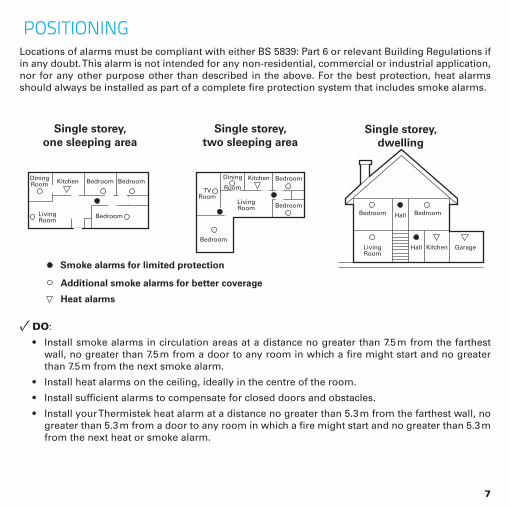
DO:
• Install smoke alarms in circulation areas at a distance no greater than 7 5 m from the farthest wall, no greater than 7 5 m from a door to any room in which a fire might start and no greater than 7 5 m from the next smoke alarm
• Install heat alarms on the ceiling, ideally in the centre of the room
• Install sufficient alarms to compensate for closed doors and obstacles
• Install your Thermistek heat alarm at a distance no greater than 5 3 m from the farthest wall, no greater than 5 3 m from a door to any room in which a fire might start and no greater than 5 3 m from the next heat or smoke alarm
✓
POSITIONINGLocations of alarms must be compliant with either BS 5839: Part 6 or relevant Building Regulations if in any doubt This alarm is not intended for any non-residential, commercial or industrial application, nor for any other purpose other than described in the above For the best protection, heat alarms should always be installed as part of a complete fire protection system that includes smoke alarms
Smoke alarms for limited protection
Single storey,one sleeping area
Single storey,two sleeping area
Single storey,dwelling
Additional smoke alarms for better coverage
Heat alarms
DiningRoom
TVRoom
LivingRoom
LivingRoom
LivingRoom
Hall
Hall
Kitchen Kitchen
Kitchen Garage
BedroomDining
RoomBedroom
BedroomBedroom BedroomBedroom
Bedroom
Bedroom
7
SYSTEM GRADES AND CATEGORIES
The mains powered SONA™ alarms with 10 year life are suitable for Grade D systems It is important to determine the correct alarm system grade and category for the dwelling prior to installation
A Grade D system is required for:
• New or materially altered dwellings, up to three storeys with no floor exceeding 200 m2
• Existing dwellings with poor or inadequate fire protection, up to three storeys with no floor exceeding 200 m2
• Individual dwelling units of two or more rooms in Houses in Multiple Occupation (HMOs) of one or two-storeys, with no floor exceeding 200 m2
There are three Levels of Detection (LD) Generally the greater the fire risk the more comprehensive the system should be
LD1 = Maximum Protection Alarms in all circulation spaces that form part of escape routes and all areas where a fire might start
LD2 = Medium Protection All circulation spaces and escape routes (e g hallways and landings) are covered together with a provision of higher fire risk areas (e g kitchen and living rooms)
LD3 = Minimum Protection Alarms in all circulation spaces that form part of escape routes
* Ensure that a Grade D system is adequate for the dwelling you are installing the alarms in
DO:
• Install smoke alarms in circulation areas at a distance no greater than 7 5 m from the farthest wall, no greater than 7 5 m from a door to any room in which a fire might start and no greater than 7 5 m from the next smoke alarm
• Install heat alarms on the ceiling, ideally in the centre of the room
• Install sufficient alarms to compensate for closed doors and obstacles
• Install your Thermistek heat alarm at a distance no greater than 5 3 m from the farthest wall, no greater than 5 3 m from a door to any room in which a fire might start and no greater than 5 3 m from the next heat or smoke alarm
✓
POSITIONINGLocations of alarms must be compliant with either BS 5839: Part 6 or relevant Building Regulations if in any doubt This alarm is not intended for any non-residential, commercial or industrial application, nor for any other purpose other than described in the above For the best protection, heat alarms should always be installed as part of a complete fire protection system that includes smoke alarms
Smoke alarms for limited protection
Single storey,one sleeping area
Single storey,two sleeping area
Single storey,dwelling
Additional smoke alarms for better coverage
Heat alarms
DiningRoom
TVRoom
LivingRoom
LivingRoom
LivingRoom
Hall
Hall
Kitchen Kitchen
Kitchen Garage
BedroomDining
RoomBedroom
BedroomBedroom BedroomBedroom
Bedroom
Bedroom

8
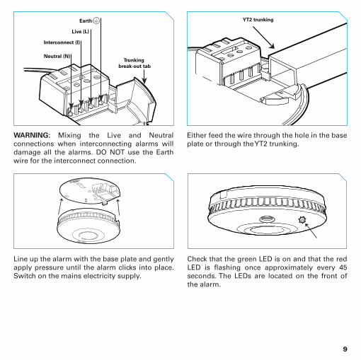
HARDWIRE INSTALLATIONThe alarm base plate is designed to be permanently mounted, using its own built-in terminal block to connect it to the mains The base plate can be screwed directly to the ceiling
• IMPORTANT: The circuit used to power the alarm must be a 24 hour voltage circuit that cannot be turned off by a switch BS 5839: Part 6 states that: For mains powered alarms, each with an integral standby supply (Grade D), the mains electricity supply should take the form of either a) an independent circuit at the dwelling’s main circuit board, in which case no other electrical equipment should be connected to this circuit (other than a dedicated monitoring device installed to indicate failure of the mains electricity supply to the alarms); or b) a separately electrically protected, regularly used local lighting circuit
• Ensure a permanent connection to the fixed wiring of the building is made in a suitable junction box
• Remove the terminal block cover
• If trunking is required, snap the break-out tab away from the base plate prior to connection
• The wiring must be connected to the terminal block as follows:
Live (L) - Connect to the Live in the house wiring
Neutral (N) - Connect to the Neutral in the house wiring
Interconnect (I) - If desired, join the Interconnect wire between the alarms
• Use the terminal to safely terminate any copper Earth or green / yellow cable
× DO NOT:
• Install the alarms within 1500 mm (1 5 m) of a fluorescent light fitting and keep wiring at least 1000 mm (1 m) from these fittings
• Install alarms on circuits containing fluorescent light fittings or dimmer switches
• Install alarms within 300 mm (12”) of light fittings or room corners
• Install smoke alarms in wall positions that are less than 100 mm (4”) or more than 300 mm (12”) away from the ceiling
• Locate the Thermoptek smoke alarm close to bathrooms or showers as it can be susceptible to nuisance alarms from steam
• Install heat alarms on a wall
WARNING: Mixing the Live and Neutral connections when interconnecting alarms will damage all the alarms DO NOT use the Earth wire for the interconnect connection
Neutral (N)
Interconnect (I)
Live (L)
Earth
Trunking break-out tab
Line up the alarm with the base plate and gently apply pressure until the alarm clicks into place Switch on the mains electricity supply
9
HARDWIRE INSTALLATIONThe alarm base plate is designed to be permanently mounted, using its own built-in terminal block to connect it to the mains The base plate can be screwed directly to the ceiling
• IMPORTANT: The circuit used to power the alarm must be a 24 hour voltage circuit that cannot be turned off by a switch BS 5839: Part 6 states that: For mains powered alarms, each with an integral standby supply (Grade D), the mains electricity supply should take the form of either a) an independent circuit at the dwelling’s main circuit board, in which case no other electrical equipment should be connected to this circuit (other than a dedicated monitoring device installed to indicate failure of the mains electricity supply to the alarms); or b) a separately electrically protected, regularly used local lighting circuit
• Ensure a permanent connection to the fixed wiring of the building is made in a suitable junction box
• Remove the terminal block cover
• If trunking is required, snap the break-out tab away from the base plate prior to connection
• The wiring must be connected to the terminal block as follows:
Live (L) - Connect to the Live in the house wiring
Neutral (N) - Connect to the Neutral in the house wiring
Interconnect (I) - If desired, join the Interconnect wire between the alarms
• Use the terminal to safely terminate any copper Earth or green / yellow cable
DO NOT:
• Install the alarms within 1500 mm (1 5 m) of a fluorescent light fitting and keep wiring at least 1000 mm (1 m) from these fittings
• Install alarms on circuits containing fluorescent light fittings or dimmer switches
• Install alarms within 300 mm (12”) of light fittings or room corners
• Install smoke alarms in wall positions that are less than 100 mm (4”) or more than 300 mm (12”) away from the ceiling
• Locate the Thermoptek smoke alarm close to bathrooms or showers as it can be susceptible to nuisance alarms from steam
• Install heat alarms on a wall
YT2 trunking
WARNING: Mixing the Live and Neutral connections when interconnecting alarms will damage all the alarms DO NOT use the Earth wire for the interconnect connection
Either feed the wire through the hole in the base plate or through the YT2 trunking
Neutral (N)
Interconnect (I)
Live (L)
Earth
Trunking break-out tab
Line up the alarm with the base plate and gently apply pressure until the alarm clicks into place Switch on the mains electricity supply
Check that the green LED is on and that the red LED is flashing once approximately every 45 seconds The LEDs are located on the front of the alarm

10
×
HARDWIRE INTERCONNECT - SM-SN-1 and HM-SN-1
DO NOT:
• Exceed the maximum of 30 interconnected alarms on a network
• Exceed 250 m of connecting wire per circuit
• Connect SONA alarms to any other models produced by another manufacturer
For multiple alarm installations use a ‘three core and earth’ style cable between all the alarms to be interconnected Connect the interconnect cable between each alarms 'I' terminal The interconnect wire (minimum 0 75 mm2 cable) must be treated as Live, it should be insulated and sheathed
Mains 230V ACPower Supply
WIRING KEY
= Live= Interconnect= Neutral
= Earth
To other alarmsif fitted
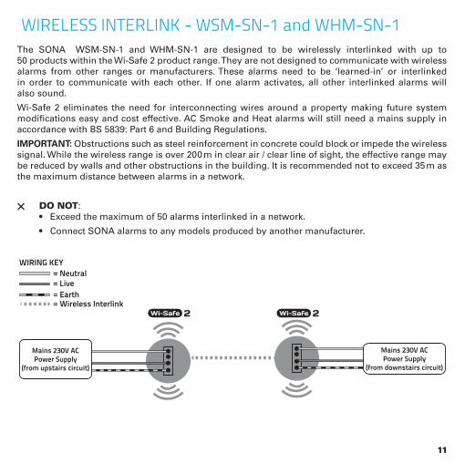
× DO NOT: • Exceed the maximum of 50 alarms interlinked in a network
• Connect SONA alarms to any models produced by another manufacturer
The SONA WSM-SN-1 and WHM-SN-1 are designed to be wirelessly interlinked with up to 50 products within the Wi-Safe 2 product range They are not designed to communicate with wireless alarms from other ranges or manufacturers These alarms need to be ‘learned-in’ or interlinked in order to communicate with each other If one alarm activates, all other interlinked alarms will also sound
Wi-Safe 2 eliminates the need for interconnecting wires around a property making future system modifications easy and cost effective AC Smoke and Heat alarms will still need a mains supply in accordance with BS 5839: Part 6 and Building Regulations
IMPORTANT: Obstructions such as steel reinforcement in concrete could block or impede the wireless signal While the wireless range is over 200 m in clear air / clear line of sight, the effective range may be reduced by walls and other obstructions in the building It is recommended not to exceed 35 m as the maximum distance between alarms in a network
WIRING KEY
= Live= Neutral
= Earth= Wireless Interlink
Mains 230V ACPower Supply
(from downstairs circuit)
Mains 230V ACPower Supply
(from upstairs circuit)
WIRELESS INTERLINK - WSM-SN-1 and WHM-SN-1
11
HARDWIRE INTERCONNECT - SM-SN-1 and HM-SN-1For multiple alarm installations use a ‘three core and earth’ style cable between all the alarms to be interconnected Connect the interconnect cable between each alarms 'I' terminal The interconnect wire (minimum 0 75 mm2 cable) must be treated as Live, it should be insulated and sheathed
Mains 230V ACPower Supply
WIRING KEY
= Live= Interconnect= Neutral
= Earth
To other alarmsif fitted
× DO NOT: • Exceed the maximum of 50 alarms interlinked in a network
• Connect SONA alarms to any models produced by another manufacturer
The SONA WSM-SN-1 and WHM-SN-1 are designed to be wirelessly interlinked with up to 50 products within the Wi-Safe 2 product range They are not designed to communicate with wireless alarms from other ranges or manufacturers These alarms need to be ‘learned-in’ or interlinked in order to communicate with each other If one alarm activates, all other interlinked alarms will also sound
Wi-Safe 2 eliminates the need for interconnecting wires around a property making future system modifications easy and cost effective AC Smoke and Heat alarms will still need a mains supply in accordance with BS 5839: Part 6 and Building Regulations
IMPORTANT: Obstructions such as steel reinforcement in concrete could block or impede the wireless signal While the wireless range is over 200 m in clear air / clear line of sight, the effective range may be reduced by walls and other obstructions in the building It is recommended not to exceed 35 m as the maximum distance between alarms in a network
WIRING KEY
= Live= Neutral
= Earth= Wireless Interlink
Mains 230V ACPower Supply
(from downstairs circuit)
Mains 230V ACPower Supply
(from upstairs circuit)
WIRELESS INTERLINK - WSM-SN-1 and WHM-SN-1
12
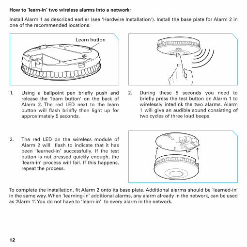
How to ‘learn-in’ two wireless alarms into a network:
Install Alarm 1 as described earlier (see 'Hardwire Installation') Install the base plate for Alarm 2 in one of the recommended locations
1 Using a ballpoint pen briefly push and release the 'learn button' on the back of Alarm 2 The red LED next to the learn button will flash briefly then light up for approximately 5 seconds
2 During these 5 seconds you need to briefly press the test button on Alarm 1 to wirelessly interlink the two alarms Alarm 1 will give an audible sound consisting of two cycles of three loud beeps
3 The red LED on the wireless module of Alarm 2 will flash to indicate that it has been ‘learned-in’ successfully If the test button is not pressed quickly enough, the ‘learn-in’ process will fail If this happens, repeat the process
Learn button
To complete the installation, fit Alarm 2 onto its base plate Additional alarms should be ‘learned-in’ in the same way When ‘learning-in’ additional alarms, any alarm already in the network, can be used as ‘Alarm 1’ You do not have to ‘learn-in’ to every alarm in the network
DO: • Ensure there is only one wireless connection into each network For example if you
have a hardwired network upstairs and a wireless network downstairs only one of the hardwired products should be linked into the wireless network, connecting both systems
Interconnecting both hardwired and wireless products together in a network:
✓
Mains 230V ACPower Supply
(from upstairs circuit)
WIRING KEY
= Live= Interconnect= Neutral
= Earth= Wireless Interlink
Mains 230V ACPower Supply
(from downstairs circuit)
Battery operated alarms
MIXED SYSTEMS

13
How to ‘learn-in’ two wireless alarms into a network:
Install Alarm 1 as described earlier (see 'Hardwire Installation') Install the base plate for Alarm 2 in one of the recommended locations
2 During these 5 seconds you need to briefly press the test button on Alarm 1 to wirelessly interlink the two alarms Alarm 1 will give an audible sound consisting of two cycles of three loud beeps
To complete the installation, fit Alarm 2 onto its base plate Additional alarms should be ‘learned-in’ in the same way When ‘learning-in’ additional alarms, any alarm already in the network, can be used as ‘Alarm 1’ You do not have to ‘learn-in’ to every alarm in the network
DO: • Ensure there is only one wireless connection into each network For example if you
have a hardwired network upstairs and a wireless network downstairs only one of the hardwired products should be linked into the wireless network, connecting both systems
Interconnecting both hardwired and wireless products together in a network:
✓
Mains 230V ACPower Supply
(from upstairs circuit)
WIRING KEY
= Live= Interconnect= Neutral
= Earth= Wireless Interlink
Mains 230V ACPower Supply
(from downstairs circuit)
Battery operated alarms
MIXED SYSTEMS

14
ALARM TEST
1 Check the red operating LED fl ashes once every 45 seconds in standby mode
2 Briefl y press the test button in the centre and release
3 An audible alarm consisting of two cycles of three loud beeps should occur and then stop automatically
4 The red LED on the alarm will fl ash rapidly during the audible signal
• Remove the dust cover from each alarm before use
• Test the alarms on a weekly basis
• Keep this guide in a safe place for future reference
• Test all alarms after repositioning large items of furniture to ensure they still work
Dust cap
USER GUIDE ALARM SMART SILENCE™Your alarm features 'Smart Silence' technology In the event of a known false alarm your alarm can be temporarily silenced by pressing the central test button Your alarm will automatically return to full sensitivity within 10 minutes
During the reduced sensitivity mode the red LED on your alarm will continue to fl ash more rapidly than normal, approximately once every 10 seconds Only use the alarm silence function after making sure that there is no fi re emergency situation Do not block the vents on the alarm or disable the alarm in any way, as this will remove your protection
NOTE: If the level of heat / smoke reaching the alarm is very high the alarm silence will be overridden and the alarm will continue to sound
SLEEP EASY™Low battery warnings often start at night or when it may be inconvenient to replace your alarm You can silence the audible 'low battery' chirp for a period of 8 hours by pressing the test button After this period the audible chirp will start again This process can be repeated for a maximum of 10 times Your alarm will still detect heat / smoke during this time, however you must replace your alarm within 30 days, as it may have insuffi cient power to warn you of a real fi re situation after this time WARNING: Your alarm cannot be silenced if the chirp is indicating a fault In this instance, the unit should be replaced immediately to ensure protection in the event of a fi re

15
ALARM TEST
2 Briefly press the test button in the centre and release
4 The red LED on the alarm will flash rapidly during the audible signal
Dust cap
USER GUIDE ALARM SMART SILENCE™Your alarm features 'Smart Silence' technology In the event of a known false alarm your alarm can be temporarily silenced by pressing the central test button Your alarm will automatically return to full sensitivity within 10 minutes
During the reduced sensitivity mode the red LED on your alarm will continue to flash more rapidly than normal, approximately once every 10 seconds Only use the alarm silence function after making sure that there is no fire emergency situation Do not block the vents on the alarm or disable the alarm in any way, as this will remove your protection
NOTE: If the level of heat / smoke reaching the alarm is very high the alarm silence will be overridden and the alarm will continue to sound
SLEEP EASY™Low battery warnings often start at night or when it may be inconvenient to replace your alarm You can silence the audible 'low battery' chirp for a period of 8 hours by pressing the test button After this period the audible chirp will start again This process can be repeated for a maximum of 10 times Your alarm will still detect heat / smoke during this time, however you must replace your alarm within 30 days, as it may have insufficient power to warn you of a real fire situation after this time WARNING: Your alarm cannot be silenced if the chirp is indicating a fault In this instance, the unit should be replaced immediately to ensure protection in the event of a fire

16
TROUBLESHOOTINGProblem Solution
Your SONA alarm does not sound during testing
• Make sure you push the centre of the test button firmly
• If the alarm has been recently fitted and it still fails to self test then contact Technical Support
• If you are in the process of 'learning-in' the alarm and it does not test, repeat the process
The green LED does not illuminate when the mains power is on
• Make sure the alarm is correctly located on the base plate
• Ensure the mains power supply is on
• Inspect the circuit breaker / fuse in the power circuit to the alarm
• Call a qualified electrician to inspect the house wiring and connection
The amber LED is flashing and the alarm is making a 'chirping' sound
• If the amber LED is flashing at the same time as the chirp, this indicates a low battery condition and the alarm should be replaced as soon as possible and certainly within 30 days
• If the amber LED is flashing at a different time to the chirp, this indicates a fault and the alarm should be replaced as soon as possible
• If the amber LED is double flashing and the alarm is making a 'chirping' sound, this indicates that the wireless module has a low battery condition, or is faulty The alarm should be replaced as soon as possible
Your SONA alarm chirps intermittently
• Check the location of your alarm (see ‘Positioning’)
• Check that your alarm is definitely the source of chirping; make sure the noise isn’t coming from another alarm
• If the alarm is chirping once approximately every 45 seconds and the amber LED is flashing around the same time, it indicates that the battery is low The unit should be replaced within 30 days
• If the alarm is chirping once every 4 hours, it is indicating that another alarm in the network has entered a low battery condition Locate the alarm with the low battery and replace the alarm as soon as possible and in any event within 30 days
Your SONA alarm fails to successfully learn-in to a network
• Make sure your alarm is 'unlearned' before trying to learn-in to a network Do this by pressing and releasing the learn-in button located on the back of the alarm, immediately press and hold the learn-in button, during which the red LED will remain solid When the LED goes out, release the button The LED will flash twice followed by three quick flashes, indicating that it has successfully been unlearned You can then follow the learn-in process as described in 'Wireless Interlink'
Other interlinked units fail to silence when one unit is silenced
• Interlinked units that have sensed smoke / heat can’t be silenced remotely If one or more units remain in alarm, all other interlinked units will emit their audible warning again within 4 minutes Vacate property if there is a fire hazard
WARNING: Storage in low humidity and certain transportation conditions may cause electrostatic charges to build up in the alarm system housing. Although harmless this may increase the length of time that the horn sounds upon test button operation. The condition may be cleared by wiping the inside and outside of the plastic cover with a damp cloth.
If you have any questions about the operation of your alarm, please contact Technical Support between 9am - 5pm Monday – Friday. Telephone: 0800 171 2009 or e-mail: [email protected] You can also visit the support section of our website www.sonasafety.com.
17
TROUBLESHOOTINGProblem Solution
Your SONA alarm does not sound during testing
• Make sure you push the centre of the test button firmly
• If the alarm has been recently fitted and it still fails to self test then contact Technical Support
• If you are in the process of 'learning-in' the alarm and it does not test, repeat the process
The green LED does not illuminate when the mains power is on
• Make sure the alarm is correctly located on the base plate
• Ensure the mains power supply is on
• Inspect the circuit breaker / fuse in the power circuit to the alarm
• Call a qualified electrician to inspect the house wiring and connection
The amber LED is flashing and the alarm is making a 'chirping' sound
• If the amber LED is flashing at the same time as the chirp, this indicates a low battery condition and the alarm should be replaced as soon as possible and certainly within 30 days
• If the amber LED is flashing at a different time to the chirp, this indicates a fault and the alarm should be replaced as soon as possible
• If the amber LED is double flashing and the alarm is making a 'chirping' sound, this indicates that the wireless module has a low battery condition, or is faulty The alarm should be replaced as soon as possible
Your SONA alarm chirps intermittently
• Check the location of your alarm (see ‘Positioning’)
• Check that your alarm is definitely the source of chirping; make sure the noise isn’t coming from another alarm
• If the alarm is chirping once approximately every 45 seconds and the amber LED is flashing around the same time, it indicates that the battery is low The unit should be replaced within 30 days
• If the alarm is chirping once every 4 hours, it is indicating that another alarm in the network has entered a low battery condition Locate the alarm with the low battery and replace the alarm as soon as possible and in any event within 30 days
Your SONA alarm fails to successfully learn-in to a network
• Make sure your alarm is 'unlearned' before trying to learn-in to a network Do this by pressing and releasing the learn-in button located on the back of the alarm, immediately press and hold the learn-in button, during which the red LED will remain solid When the LED goes out, release the button The LED will flash twice followed by three quick flashes, indicating that it has successfully been unlearned You can then follow the learn-in process as described in 'Wireless Interlink'
Other interlinked units fail to silence when one unit is silenced
• Interlinked units that have sensed smoke / heat can’t be silenced remotely If one or more units remain in alarm, all other interlinked units will emit their audible warning again within 4 minutes Vacate property if there is a fire hazard
WARNING: Storage in low humidity and certain transportation conditions may cause electrostatic charges to build up in the alarm system housing. Although harmless this may increase the length of time that the horn sounds upon test button operation. The condition may be cleared by wiping the inside and outside of the plastic cover with a damp cloth.
If you have any questions about the operation of your alarm, please contact Technical Support between 9am - 5pm Monday – Friday. Telephone: 0800 171 2009 or e-mail: [email protected] You can also visit the support section of our website www.sonasafety.com.

18
BE PREPAREDSmoke and heat alarms properly installed and maintained are an essential part of a good home safety programme Review fire hazards and eliminate dangerous conditions whenever possible When fire strikes, a prepared and practised escape plan could prove vital Consider and discuss the following hints:
• Ensure everyone is familiarised with the alarm signal
• Always test doors with your hands before flinging them open If they feel warm, fire may have walled up behind them – leave closed and find another escape route
• Don’t waste time collecting possessions Arouse all occupants and leave the building Your life is more valuable!
• GET OUT, STAY OUT, GET THE FIRE BRIGADE OUT.
• Keep everyone in a set meeting place after you escape
• If trapped inside, stay close to the floor, cover your mouth with a cloth and conserve breath as you crawl to safety
• Keep all windows and doors closed except for escape purposes
• Prepare and practice an escape plan before a fire starts
• Draw a floor plan Have fire drills often Practise your escape
DISPOSALWaste electrical products should not be disposed of with your other household waste The alarm is ideally suited for
disposal within the waste electronic and electrical equipment (WEEE) recycling scheme Please recycle where facilities
exist Check with your local authority, retailer or contact Technical Support for recycling/disposal advice as regional
variations apply Your alarm can be unlearned from a network, as described in 'Troubleshooting' Once it is removed
from its base plate it is automatically disabled and ready to be disposed of
WARNING: Do not burn or dispose of in fire WARNING: If your alarm is dropped or damaged, as a precaution, it should be
removed from the building
Insert screwdriver here
MAINTENANCE
IF THERE IS ANY QUESTION AS TO THE CAUSE OF THE ALARM, ALWAYS ASSUME THAT THIS IS AN ACTUAL FIRE AND FOLLOW YOUR FIRE EMERGENCY PLANS.

19
BE PREPAREDSmoke and heat alarms properly installed and maintained are an essential part of a good home safety programme Review fire hazards and eliminate dangerous conditions whenever possible When fire strikes, a prepared and practised escape plan could prove vital Consider and discuss the following hints:
• Keep everyone in a set meeting place after you escape
• If trapped inside, stay close to the floor, cover your mouth with a cloth and conserve breath as you crawl to safety
• Keep all windows and doors closed except for escape purposes
• Prepare and practice an escape plan before a fire starts
• Draw a floor plan Have fire drills often Practise your escape
Your smoke and heat alarms should be cleaned every 3 months, by firstly turning off the mains electricity supply and then using a vacuum cleaner fitted with the soft brush attachment Switch the power back on once you have finished
DISPOSALWaste electrical products should not be disposed of with your other household waste The alarm is ideally suited for
disposal within the waste electronic and electrical equipment (WEEE) recycling scheme Please recycle where facilities
exist Check with your local authority, retailer or contact Technical Support for recycling/disposal advice as regional
variations apply Your alarm can be unlearned from a network, as described in 'Troubleshooting' Once it is removed
from its base plate it is automatically disabled and ready to be disposed of
WARNING: Do not burn or dispose of in fire WARNING: If your alarm is dropped or damaged, as a precaution, it should be
removed from the building
Insert screwdriver here
MAINTENANCE
If you need to remove your alarm from its base plate, turn off the mains electricity supply, use a small screwdriver and insert into the hole at the base of the alarm (illustrated here) Push the screwdriver in and the alarm should fall free from the base plate Please be aware that the alarm will fall as soon as pressure is applied to the screwdriver, be prepared to catch it
IF THERE IS ANY QUESTION AS TO THE CAUSE OF THE ALARM, ALWAYS ASSUME THAT THIS IS AN ACTUAL FIRE AND FOLLOW YOUR FIRE EMERGENCY PLANS.

20
WARRANTYSprue Safety Products Ltd warrants to the original purchaser that its enclosed alarm be free from defects in materials and
workmanship under normal residential use and service for a period of 5 years from the date of purchase Provided it is returned
with postage prepaid and proof of purchase date, Sprue Safety Products Ltd hereby warrants that during the 5 year period
commencing from the date of purchase Sprue Safety Products Ltd, at its discretion, agrees to replace the unit free of charge
The warranty on any replacement SM-SN-1/ WSM-SN-1 / HM-SN-1 / WHM-SN-1 alarm, will last for the remainder of the period
of the original warranty in respect of the alarm originally purchased – that is from the date of original purchase and not from
the date of receipt of the replacement product Sprue Safety Products Ltd reserves the right to offer an alternative product
similar to that being replaced if the original model is no longer available or in stock This warranty applies to the original retail
purchaser from the date of original retail purchase and is not transferable Proof of purchase is required This warranty does not
cover damage resulting from accident, misuse, disassembly, abuse or lack of reasonable care of the product, or applications
not in accordance with the user guide It does not cover events and conditions outside of Sprue Safety Products Ltd’s control,
such as Acts of God (fire, severe weather etc ) It does not apply to retail stores, service centres or any distributors or agents
Sprue Safety Products Ltd will not recognise any changes to this warranty by third parties
Sprue Safety Products Ltd shall not be liable for any incidental or consequential damages caused by the breach of any
expressed or implied warranty Except to the extent prohibited by applicable law, any implied warranty of merchantability or
fitness for a particular purpose is limited in duration for 5 years This warranty does not affect your statutory rights Except for
death or personal injury, Sprue Safety Products Ltd shall not be liable for any loss of use, damage, cost or expense relating
to this product or for any indirect or consequential loss, damages or costs incurred by you or any other user of this product

21
WARRANTYSprue Safety Products Ltd warrants to the original purchaser that its enclosed alarm be free from defects in materials and
workmanship under normal residential use and service for a period of 5 years from the date of purchase Provided it is returned
with postage prepaid and proof of purchase date, Sprue Safety Products Ltd hereby warrants that during the 5 year period
commencing from the date of purchase Sprue Safety Products Ltd, at its discretion, agrees to replace the unit free of charge
The warranty on any replacement SM-SN-1/ WSM-SN-1 / HM-SN-1 / WHM-SN-1 alarm, will last for the remainder of the period
of the original warranty in respect of the alarm originally purchased – that is from the date of original purchase and not from
the date of receipt of the replacement product Sprue Safety Products Ltd reserves the right to offer an alternative product
similar to that being replaced if the original model is no longer available or in stock This warranty applies to the original retail
purchaser from the date of original retail purchase and is not transferable Proof of purchase is required This warranty does not
cover damage resulting from accident, misuse, disassembly, abuse or lack of reasonable care of the product, or applications
not in accordance with the user guide It does not cover events and conditions outside of Sprue Safety Products Ltd’s control,
such as Acts of God (fire, severe weather etc ) It does not apply to retail stores, service centres or any distributors or agents
Sprue Safety Products Ltd will not recognise any changes to this warranty by third parties
Sprue Safety Products Ltd shall not be liable for any incidental or consequential damages caused by the breach of any
expressed or implied warranty Except to the extent prohibited by applicable law, any implied warranty of merchantability or
fitness for a particular purpose is limited in duration for 5 years This warranty does not affect your statutory rights Except for
death or personal injury, Sprue Safety Products Ltd shall not be liable for any loss of use, damage, cost or expense relating
to this product or for any indirect or consequential loss, damages or costs incurred by you or any other user of this product

22

23

24
Available on all wireless products
Carbon Monoxide AlarmWireless: WCOB-SN-1
Heat AlarmWireless: WHM-SN-1
Non-wireless: HM-SN-1
Smoke AlarmWireless: WSM-SN-1
Non-wireless: SM-SN-1Alarm Control Unit
Wireless: WTSL-SN-1