Embed Size (px)
Citation preview
Installation and user guide
Accumulator tanks
© Danfoss A/S 2014-04 VUILB202 1
2 VUILB202 © Danfoss A/S 2014-04
Danfoss A/S is not liable or bound by warranty if theseinstructions are not adhered to during installation or service.The English language is used for the original instructions.Other languages are a translation of the original instructions.(Directive 2006/42/EC)© Copyright Danfoss A/S
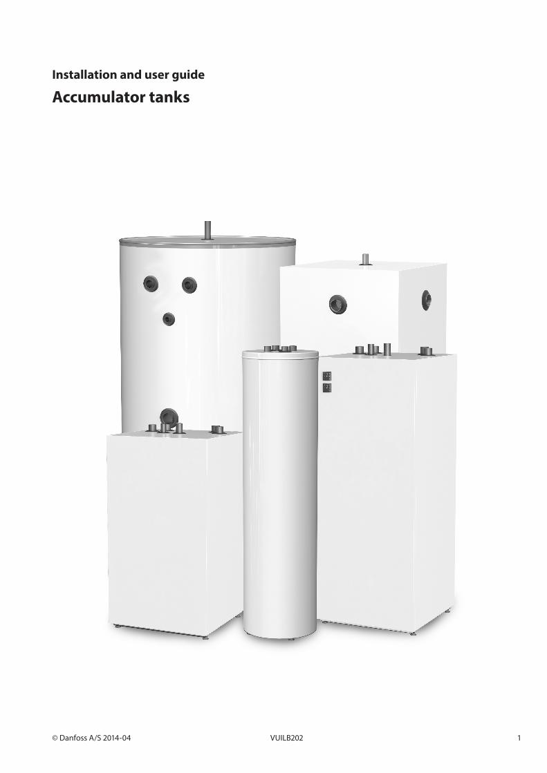
Installation The accumulator tank should stand on a solid surface and be leveled with assistance from the setscrews underneath the tank. The tank models that come without setscrews can be leveled with assistance of a shim. This must be done before the tank is connected to the pipes and filled with water. Connections not in use must be plugged appropriately. During water filling, condensed water may emerge on the outside of the tank. This will result in water underneath the tank, on the floor. This will cease when the tank is heated. There must be a floor drain in the same room.
Commissioning
Start by filling the tank, then pressurize it. Continue to fill the radiator system (the enclosed water). The working pressure may not exceed 3 bar (gauge), a safety valve with a releasing pressure of 3 bar must always be installed.
Maintenance Check the safety valve annually by manually opening and closing the valve handle and making sure that water is released. Check annually all connections for eventual leakage (also peripheral installations, i.e. a heat pump, etc).
Electrical Installation
• The electrical installation must be performed by an authorised installer and follow applicable norms and regulations.
• When selecting electrical equipment, it must be selected with approved materials and enclosure class.
WT-V 100 200 300 500 1000
Height (mm) 1550 1160 1570 1730 1830
Dimensions with insulation (mm) ø410 600 x 600 600 x 600 ø700 ø1100
Dimensions without insulation (mm) - - - - ø900
Dimensions
WT-V 100 200 300 500 1000
Volume hot water accumulator 102 litres 200 litres 300 litres 500 litres 1000 litres
Test pressure 4,3 bar 4,3 bar 4,3 bar 4,3 bar 4,3 bar
Working pressure 3 bar 3 bar 3 bar 3 bar 3 bar
Rated temperature 100°C 100°C 100°C 100°C 100°C
Weight 44 kg 60 kg 72 kg 96 kg 113 kg
Technical data

© Danfoss A/S 2014-04 VUILB202 3
Connection WT-V 100
1 Venting, (1/8” int.)
2 Connections (DN 25 inv) (x4) int.
3 Sensor connection, ø9 int
4 Drain tap, DN20 int.
0
2
31
2
2
2
100
100
40
Radiator in
Radiator out
HP in
HP out
4
1 5501 517
157
502
Dimensions
Technical data
WT-V 100Height (mm) 1550
Diameter (ømm) 410
WT-V 100Volume hot water accumulator 102 litres
Test pressure 4,3 bar
Working pressure 3 bar
Rated temperature 100 °C
Weight 44kg
ø410
4 VUILB202 © Danfoss A/S 2014-04
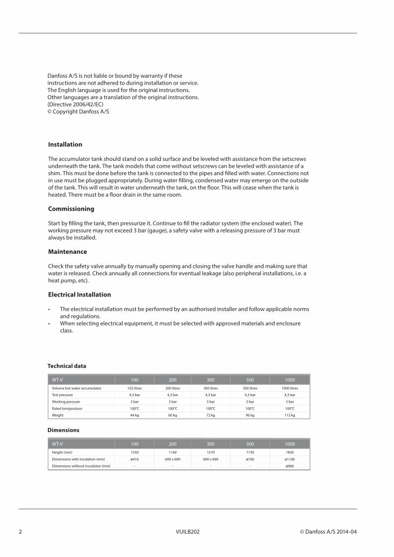
Connection WT-V 200
1 Expansion/Venting, DN25 int.
2 Connections (4x), DN32 int.
3 Temperature sensor conn. DN20 int.
4 Drainage, DN20 int.
5 Temperature sensor pipe (2x), ø9 int.
6 Diffuser
600
600
11601101
114
0
1
4
5
6
2
3
Dimensions
WT-V 200Height (mm) 1160
Dimensions (mm) 600 x 600
Technical data
WT-V 200Volume hot water accumulator 200 litres
Test pressure 4,3 bar
Working pressure 3 bar
Rated temperature 100 °C
Weight 60 kg
© Danfoss A/S 2014-04 VUILB202 5
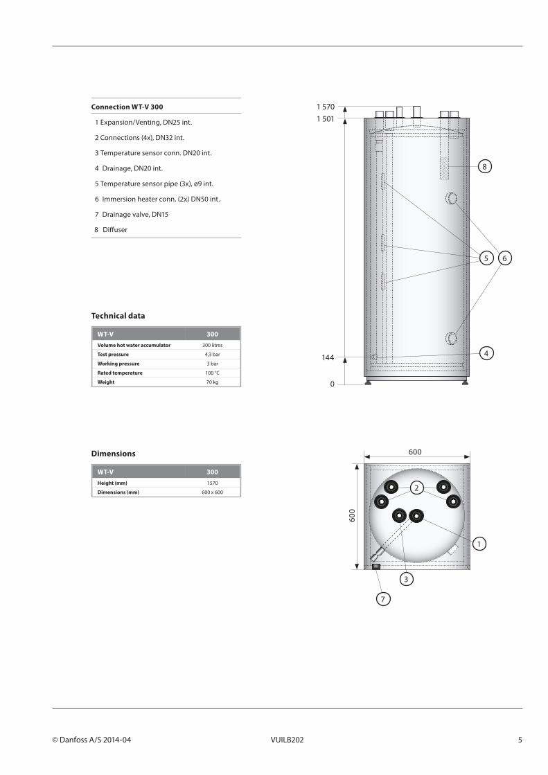
Connection WT-V 300
1 Expansion/Venting, DN25 int.
2 Connections (4x), DN32 int.
3 Temperature sensor conn. DN20 int.
4 Drainage, DN20 int.
5 Temperature sensor pipe (3x), ø9 int.
6 Immersion heater conn. (2x) DN50 int.
7 Drainage valve, DN15
8 Diffuser
600
600
0
144
1 5011 570
1
4
7
5 6
2
3
8
Dimensions
Technical data
WT-V 300Height (mm) 1570
Dimensions (mm) 600 x 600
WT-V 300Volume hot water accumulator 300 litres
Test pressure 4,3 bar
Working pressure 3 bar
Rated temperature 100 °C
Weight 70 kg

6 VUILB202 © Danfoss A/S 2014-04
Connection WT-V 500
1 Expansion/Venting, DN25 ext.
2 Connections (6x), DN50 int.
3 Temperature sensor conn. DN20
4 Immersion heater conn. DN50 int.
Required ceiling height for tilting: min. 1840mm
17301666
1480
355
180
0
2
3
1
2
4
700
730
760
Dimensions
Technical data
WT-V 500Height (mm) 1730
Dimensions (mm) 730 x 760
WT-V 500Volume hot water accumulator 500 litres
Test pressure 4,3 bar
Working pressure 3 bar
Rated temperature 100 °C
Weight 90 kg
© Danfoss A/S 2014-04 VUILB202 7
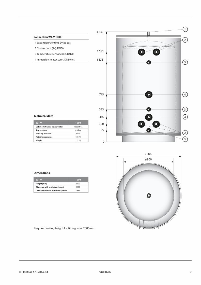
Connection WT-V 1000
1 Expansion/Venting, DN25 ext.
2 Connections (4x), DN50
3 Temperature sensor conn. DN20
4 Immersion heater conn. DN50 int.
Required ceiling height for tilting: min. 2085mm
1 830
1 515
1 335
795
545
415
300
195
1
2
2
4
4
3
3
3
ø1100
ø900
0
Dimensions
Technical data
WT-V 1000Height (mm) 1830
Diameter with insulation (ømm) 1100
Diameter without insulation (ømm) 900
WT-V 1000Volume hot water accumulator 1000 litres
Test pressure 4,3 bar
Working pressure 3 bar
Rated temperature 100 °C
Weight 113 kg

8 VUILB202 © Danfoss A/S 2014-04
Danfoss Heat PumpsBox 950SE-671 29 ARVIKAPhone +46 570 81300E-mail: [email protected]: www.heating.danfoss.com, www.thermia.com
Danfoss assumes no responsibility whatsoever for any errors occurring in catalogues, brochures or other printed material. Danfoss reserves the right to make changes to (the design of) its products with no prior warning. The same applies to products already on order provided that the previously agreed specifications remain unchanged. All trademarks in this material are the property of the respective company. Danfoss and the Danfoss logotype are trademarks which belong to Danfoss A/S. All rights reserved.