Embed Size (px)
Citation preview
Installation and use of the
the AVR assembler simulator
avr_sim
by
Gerhard Schmidt, Kastanienallee 20, D-64289 Darmstadt
Version 1.9 as of January 2020
Content1 Application conditions and hints ..................................................................3
1.1 What this software does ...........................................................................31.2 Applicability ............................................................................................31.3 Hints for using avr_sim ............................................................................41.4 Lengthy timer operations ..........................................................................5
2 Compiling avr_sim ....................................................................................62.1 Installing Lazarus ....................................................................................62.2 Compiling avr_sim ...................................................................................6
3 Installation ...............................................................................................83.1 Installing gavrasm ...................................................................................83.2 Running avr_sim for the first time .............................................................8
4 Use .........................................................................................................94.1 Opening files ...........................................................................................94.2 Device check and package selection .........................................................104.3 Editing files ...........................................................................................11
4.3.1 The editor .......................................................................................114.3.2 The editor's functions .......................................................................124.3.3 Search for and/or replacing text ........................................................134.3.4 Working in parallel with an external editor ...........................................144.3.5 Syntax highlighting ..........................................................................14
4.4 Selecting the device's clock frequency ......................................................164.5 Viewing device properties .......................................................................174.6 Starting a new project ............................................................................184.7 Adding a new include file to an existing project ..........................................21
5 Assembling .............................................................................................225.1 Starting the assembly process .................................................................225.2 Errors during assembling ........................................................................235.3 Setting/removing breakpoints .................................................................23
6 Simulating ..............................................................................................266.1 Starting simulation .................................................................................266.2 Viewing I/O ports ...................................................................................276.3 Viewing and manipulating timers .............................................................30
6.3.1 Viewing timers .................................................................................306.3.2 Changing timer values ......................................................................32
6.4 Viewing SRAM content ............................................................................326.5 Viewing EEPROM content ........................................................................336.6 Viewing and manipulating ADC content .....................................................34
6.6.1 ADC channels ..................................................................................346.6.2 Resistor matrix as voltage input source ...............................................356.6.3 Active AD conversion ........................................................................38
6.7 Scope display ........................................................................................387 Not yet implemented, but under consideration .............................................418 Not implemented and not planned .............................................................429 Changes introduced in version 1.9 .............................................................43
9.1 Changes to the integrated assembler gavrasm ...........................................439.2 Changes concerning the editor ................................................................439.3 Changes concerning the simulator ............................................................449.4 Changes of the handbook .......................................................................45
10 Known issues ..........................................................................................46
1 Application conditions and hints
1.1 What this software does
This software
• emulates micro controllers of the types AT90S, ATtiny and ATmega,
• allows to edit assembler source code for these controllers,
• assembles the source code by running the integrated assembler
gavrasm,
• simulates the generated program code as if it would run within the con-
troller itself (in single steps or continuously),
• displays the state of the hardware inside the controller (ports, timers, AD
converter, EEPROM, etc.) and allows to manipulate this.
1.2 Applicability
This software has limiting conditions as follows:
1. It is solely applicable for AVR assembler source code for AT90S, ATtiny
und ATmega devices, in limited manner also for ATxmega, of ATMEL®/
Microchip®. Other controller types such as PIC or ARM and their associ-
ated assembler dialects or compiler languages such as C are not sup-
ported.
2. It builds on relevant hardware properties of those controllers, such as
the size and location of controller internals like flash memory, EEPROM
or SRAM memories, availability and size of I/O-Ports, timers/counters,
ADC channels, availability and addresses of interrupt vectors, type spe-
cific constants such as port register addresses and port bit names, etc.
etc. It works only if the AVR device type is clearly specified with the di-
rective .include „(type abbrev.)def.inc“ or .device “(device name)”. Sub
types such as „A“ or „P“ suffixes are generally correctly recognized if
there is an include file from ATMEL® or Microchip® available. The differ-
ent availability of I/O port bits in different packages such as PDIP, SOIC
or QFN are correctly recognized if the respective package type is se-
lected.
3. It builds on the command line assembler gavrasm. Source code that is
incompatible with this assembler can not be simulated and has to be
converted (see the ReadMe file of gavrasm for the respective versions
under this link: gavrasm, also for hints on compatibility).
4. It is not tested systematically for all AVR controllers and all their internal
hardware. There might be bugs (missing hardware, non-standardized
symbols).
5. As like for all free software of this type no guarantee for bug-free func-
tioning can be given.
1.3 Hints for using avr_sim
The avr_sim executable is available in three sub-versions: one as Linux-64-Bit
and two as Windows-64-Bit versions. The 64-bit-Windows version is available
in the following two modes:
1. without integrated range checks and debug information (the executable
file is much smaller and starts more rapidly),
2. with integrated range check and debug information („debug“ in the file-
name, approx. 6 times larger).
If you encounter strange errors when working with Windows subversion 1, you
can try the second version and identify internal programming errors, such as
Range-Check errors. In that case please send feedback to me, with as-exact-
as-possible information on the circumstances when the error reproduce-ably
occurs, so that I can identify and fix the error.
If you need 32 bit versions for Windows and Linux see chapter 2.2 on how to
compile avr_sim under Lazarus.
With avr_sim you can execute any AVR assembler source code (assumed that
the conditions in chapter 1.2 are met). It assembles the source code with
gavrasm to an executable flash hex code in standard .hex format and to a
standard EEPROM hex file .eep and steps or runs through the executable in-
structions.
If only parts of the code shall be tested, unused parts of the source code can
be commented out with „;“. With the directives „.if (condition)“, „.else“ and
„.endif“ parts of the code can be selected and separated from code that is not
simulated but should be part of the final executable code for the controller. If
certain single steps shall not be executed, use the “Skip” mode for those.
1.4 Lengthy timer operations
When simulating timer operations with large prescaler values simulation can
last very long. Stopping at certain timer values, if no interrupt is executed, can
be achieved by exchanging the SLEEP instruction by additional code that de-
tects certain conditions (e.g. timer value TCNT = 255) and where breakpoints
can be set to stop the running simulation.
2 Compiling avr_simIf you have downloaded the pre-compiled version for Windows and Linux as
executable (avr_sim_vv_Win64.zip or avr_sim_vv_Lin64.zip or the respective
debug version) you can skip this chapter and proceed with the Chapter on
Installation.
If you downloaded the source files (Windows: avr_sim_vv_win_src.zip, Linux:
avr_sim_lin_vv_src.zip) the following describes the compilation of those source
files.
2.1 Installing Lazarus
To compile avr_sim you need the Open Source software Lazarus. Please down-
load Lazarus and the corresponding Free Pascal Compiler FPC for your operat-
ing system. Lazarus is available for many different operating systems and their
sub-versions and can be downloaded from their websites.
2.2 Compiling avr_sim
If you work under Windows or Linux use the respective source files for those
operating systems. If you install for a different operating system, try out both
source files or find a specific version for your operating system on the internet.
Open the file “avr_sim.lpi” which should be associated with Lazarus source
code. As first step change the target operating system and processor type. The
default in Windows source code is Win64, in Linux Lin64. To change that, open
“Project options” from the Lazarus menu and navigate to “Config and Target” in
the “Compiler options”. Choose your target operating system and your target
CPU family from the two drop-down menus.
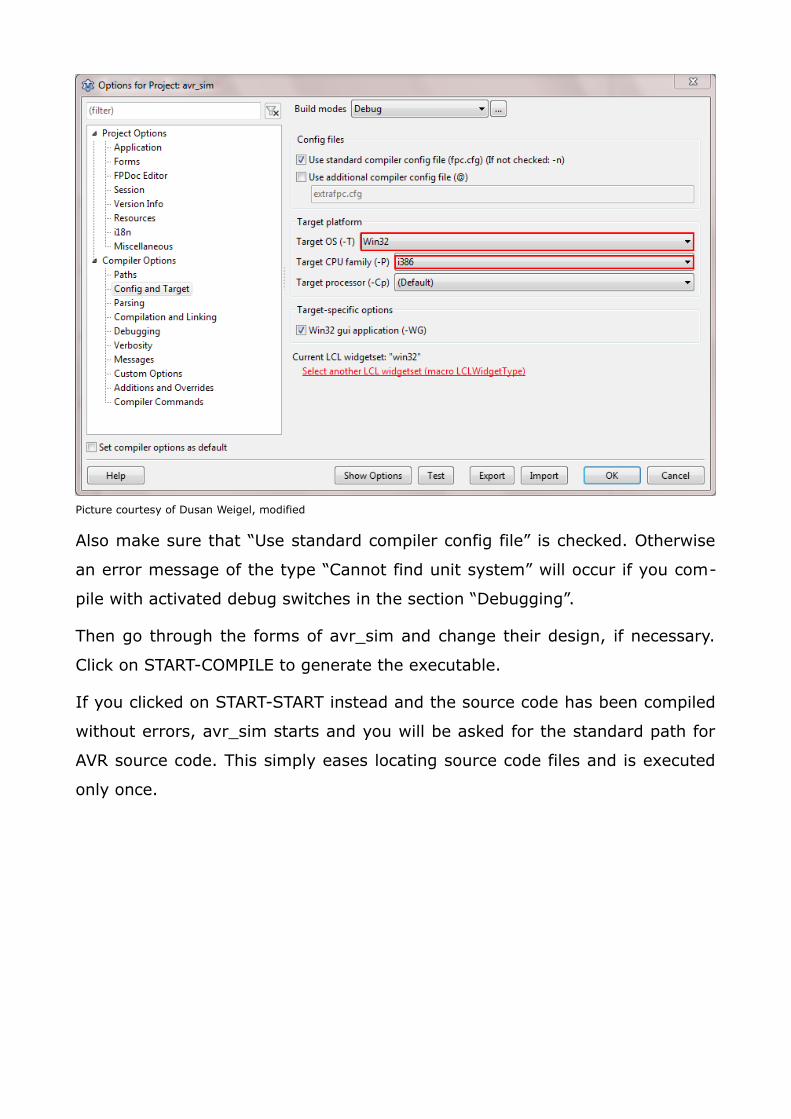
Picture courtesy of Dusan Weigel, modified
Also make sure that “Use standard compiler config file” is checked. Otherwise
an error message of the type “Cannot find unit system” will occur if you com-
pile with activated debug switches in the section “Debugging”.
Then go through the forms of avr_sim and change their design, if necessary.
Click on START-COMPILE to generate the executable.
If you clicked on START-START instead and the source code has been compiled
without errors, avr_sim starts and you will be asked for the standard path for
AVR source code. This simply eases locating source code files and is executed
only once.
3 Installation
3.1 Installing gavrasm
An extra version of gavrasm is not necessary any more, gavrasm is completely
integrated into avr_sim. The integrated version is identical to the stand-alone
version of gavrasm.
3.2 Running avr_sim for the first time
If you start avr_sim for the first time it requires you to locate the path where
you store AVR assembler projects (can have sub-paths for several different
projects, a correct path eases selection of assembler projects).
This path is stored in a text file named avr_sim.cfg, which under Windows is
located in the folder C:\Users\[user_name]\AppData\Roaming\avr_sim. Under
Linux it is located in the folder “.avr_sim” in the home directory of the current
user. If you have generated this config file with a previous version of avr_sim,
this file will be moved there. The executable can be located in a folder where
the user has no write permission to, e. g. in “/usr/bin/”.
Page 8
4 Useavr_sim can handle assembler files (extension .asm of file type plain text) and
avr-sim specific project files (extension .pro of file type plain text). If you open
an assembler file (not an included file!) avr_sim generates a default project file
for that and stores that in the folder where the assembler file is located.
4.1 Opening files
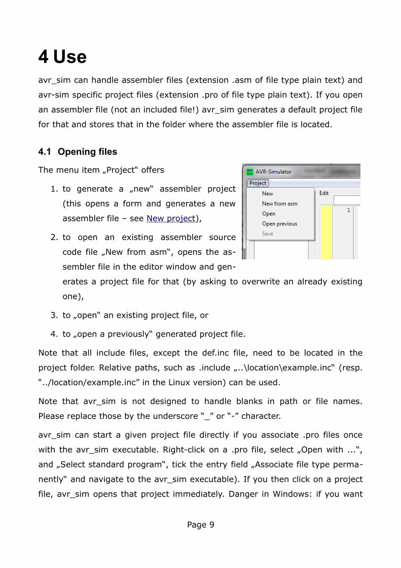
The menu item „Project“ offers
1. to generate a „new“ assembler project
(this opens a form and generates a new
assembler file – see New project),
2. to open an existing assembler source
code file „New from asm“, opens the as-
sembler file in the editor window and gen-
erates a project file for that (by asking to overwrite an already existing
one),
3. to „open“ an existing project file, or
4. to „open a previously“ generated project file.
Note that all include files, except the def.inc file, need to be located in the
project folder. Relative paths, such as .include „..\location\example.inc“ (resp.
“../location/example.inc” in the Linux version) can be used.
Note that avr_sim is not designed to handle blanks in path or file names.
Please replace those by the underscore “_” or “-” character.
avr_sim can start a given project file directly if you associate .pro files once
with the avr_sim executable. Right-click on a .pro file, select „Open with ...“,
and „Select standard program“, tick the entry field „Associate file type perma-
nently“ and navigate to the avr_sim executable). If you then click on a project
file, avr_sim opens that project immediately. Danger in Windows: if you want
Page 9
to associate .pro files with a different version of avr_sim, do not delete the
old executable! This would end up with a completely defective association. To
repair this you need to edit the Windows Registry file. Another work-around is
to rename the avr_sim.exe file to avr_sim_17.exe: by doing that you can asso-
ciate the .pro files with a certain version of avr_sim.
In the same manner avr_sim can be associated with .asm files. Either decide
to associate .asm files directly with avr_sim or, with a right-click, select „Open
with ...“ to start the .asm file with avr_sim. If a project file already exists you
are asked if you want to overwrite this. If yes, potential info in that is lost.
4.2 Device check and package selection
The device type is derived from the .include „xxxdef.inc“ directive in the source
code. In case that the device type is not included in the database of avr_sim, a
selection window opens with „0“ as device number.
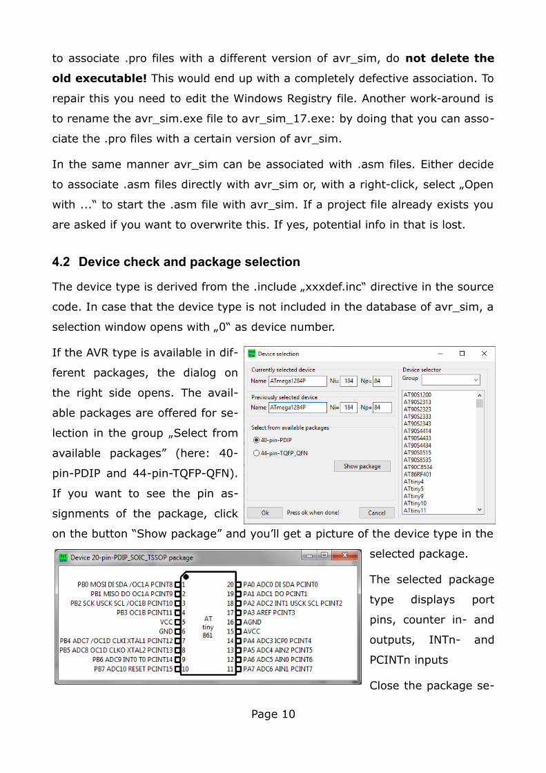
If the AVR type is available in dif-
ferent packages, the dialog on
the right side opens. The avail-
able packages are offered for se-
lection in the group „Select from
available packages” (here: 40-
pin-PDIP and 44-pin-TQFP-QFN).
If you want to see the pin as-
signments of the package, click
on the button “Show package” and you’ll get a picture of the device type in the
selected package.
The selected package
type displays port
pins, counter in- and
outputs, INTn- and
PCINTn inputs
Close the package se-
Page 10
lection with the OK button if your selection is finished.
The selected device and package type are stored in the .pro file, so you are
only asked once for the package. If you want to select another package type,
just click on “Target device:” in the project window or delete the respective line
from the .pro file with a text editor and the dialog re-appears at project start.
If you want to change the previously selected type and/or package, this can be
done with that dialog. Just enter the device name manually in the “name” edi-
tor field of the section “Currently selected device”. Devices with parts of the
currently edited name appear in the list, from which devices can also be se-
lected by clicking on them. If you want to extend the list, use the “Group”
drop-down-field above the list. Clicking selects the type and ends manual in-
put. If you are manually inputting the type and the edit field is yellow, hit the
return key to end editing. If you want to undo editing, just click into the
“Name” field below in the section “Previously selected device”, which restores
the previously selected device and package.
If you change the type of device, the .include line in the source code that de-
fines the type is also changed and the cursor of the editor is set to this line.
And, of course, the project file is rewritten and re-loaded.
4.3 Editing files
4.3.1 The editor
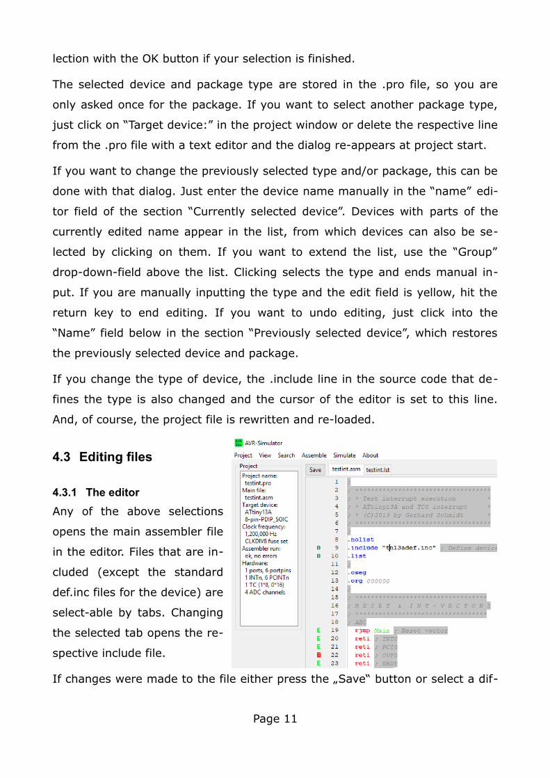
Any of the above selections
opens the main assembler file
in the editor. Files that are in-
cluded (except the standard
def.inc files for the device) are
select-able by tabs. Changing
the selected tab opens the re-
spective include file.
If changes were made to the file either press the „Save“ button or select a dif-
Page 11
ferent file and answer „Yes“ to save the file (if „No“, the changes are ignored).
Unlike other software, edited files in avr_sim are not kept internally. They are
reloaded whenever the tab changes. Therefore you are always asked if you
want to save the changes whenever you change a file’s content and you
change the tab. This allows to use external editors on files that are currently
not loaded into the editor window, such as included files (see chapter 4.3.4 for
more details).
4.3.2 The editor's functions
The editor allows to perform the following useful functions with those key as-
signments:
• Alt-Backspace or Strg-Z: undo the last change,
• Ctrl-C: copy the marked text to the clipboard,
• Ctrl-V: insert the text in the clipboard at the current cursor location,
• Ctrl-A: mark the whole text,
• Ctrl-X: cut out the marked text,
• Shift-key Ctrl-N: set the markers N (1..9),
• Ctrl-N: go to the markers 1 to 9,
• Ins: toggle between overwriting and inserting.
All key functions of the editor are displayed in a window if the function key F1
is pressed.
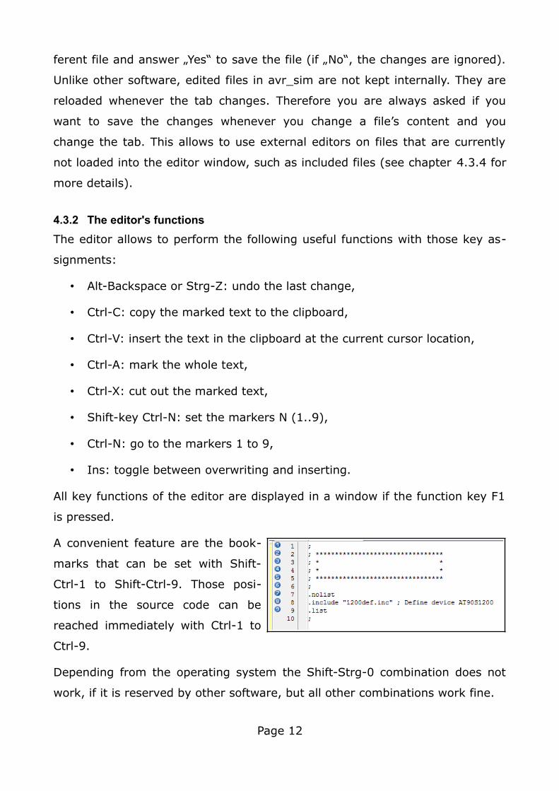
A convenient feature are the book-
marks that can be set with Shift-
Ctrl-1 to Shift-Ctrl-9. Those posi-
tions in the source code can be
reached immediately with Ctrl-1 to
Ctrl-9.
Depending from the operating system the Shift-Strg-0 combination does not
work, if it is reserved by other software, but all other combinations work fine.
Page 12
All edited files have their own bookmarks, those are stored in the project file
and are restored when the project is loaded.
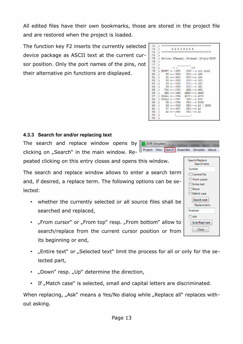
The function key F2 inserts the currently selected
device package as ASCII text at the current cur-
sor position. Only the port names of the pins, not
their alternative pin functions are displayed.
4.3.3 Search for and/or replacing text
The search and replace window opens by
clicking on „Search“ in the main window. Re-
peated clicking on this entry closes and opens this window.
The search and replace window allows to enter a search term
and, if desired, a replace term. The following options can be se-
lected:
• whether the currently selected or all source files shall be
searched and replaced,
• „From cursor“ or „From top“ resp. „From bottom“ allow to
search/replace from the current cursor position or from
its beginning or end,
• „Entire text“ or „Selected text“ limit the process for all or only for the se-
lected part,
• „Down“ resp. „Up“ determine the direction,
• If „Match case“ is selected, small and capital letters are discriminated.
When replacing, „Ask“ means a Yes/No dialog while „Replace all“ replaces with-
out asking.
Page 13
4.3.4 Working in parallel with an external editor
If you sometimes work with an external editor please consider the following:
• avr_sim's editor loads the current versions of files whenever the tab se-
lector changes. So having the editor displaying the list file, an external
editor can be used to change the .asm and any .inc files. After finishing
external work on files, just change back to the tab of the desired file and
the (externally changed) content is re-loaded. If large changes were
made it might be useful to re-load the whole project and to re-assemble.
This re-news the executable qualification of all files and ensures that
breakpoint setting and removal works correct.
• If you want to keep the current content of an edited file while temporar-
ily working on it externally, select the tab of this file and do the external
work. If finalized, you'll be asked if you want to reload the externally
changed file. If you answer No, the external changes are overwritten by
the version in avr_sim's editor.
• Note that the Studio assembler deletes, not by default but if selected,
the .lst file and, if enabled, overwrites the list file using a different for-
mat. Listings that were not generated by gavrasm are detected and re-
assembling with gavrasm is required.
The text editor used has to store plain text without additional formatting infor-
mation such as ANSI-escape-sequences for text colors, etc. Assembler source
code files shall only use 7-bit-ASCII characters, do not use any country-specific
character sets in your source code. The code that the editor produces shall be
ANSI, other text formats such as UTF8 or others are not working correct.
4.3.5 Syntax highlighting
From version 1.7 on the editor is able to highlight syntax elements in AVR as-
sembler language. That means that the editor can display specific elements of
the source code in select-able foreground and background colors as well as
with select-able text styles.
Page 14
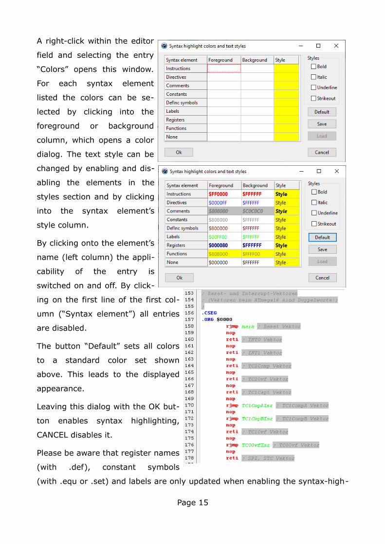
A right-click within the editor
field and selecting the entry
“Colors” opens this window.
For each syntax element
listed the colors can be se-
lected by clicking into the
foreground or background
column, which opens a color
dialog. The text style can be
changed by enabling and dis-
abling the elements in the
styles section and by clicking
into the syntax element’s
style column.
By clicking onto the element’s
name (left column) the appli-
cability of the entry is
switched on and off. By click-
ing on the first line of the first col-
umn (“Syntax element”) all entries
are disabled.
The button “Default” sets all colors
to a standard color set shown
above. This leads to the displayed
appearance.
Leaving this dialog with the OK but-
ton enables syntax highlighting,
CANCEL disables it.
Please be aware that register names
(with .def), constant symbols
(with .equ or .set) and labels are only updated when enabling the syntax-high-
Page 15
lighting. So, after larger changes to the source code switch syntax-highlighting
off and on to update these lists. The def.inc symbols are only updated during
project loading.
Syntax-highlighting is disabled by default, but if you press the “Save” button
and leave the dialog with “Ok” it writes the current color set to the avr_sim.cfg
file and avr_sim starts with that set and enables syntax-highlighting. If a color
set in avr_sim.cfg is available, you can read it with the “Load” button. If you
leave the dialog with the “Save” and “CANCEL” button, the entry in avr_sim.cfg
is deleted.
Each project also stores the current color and style set in its project file and re-
stores the color set when re-opening the project file. The settings in the
project file overwrite the settings in avr_sim.cfg, so each project can use its
own color and style set.
Please note that the bold style does not yet work as designed.
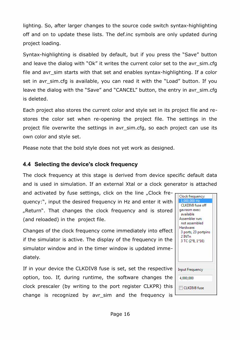
4.4 Selecting the device's clock frequency
The clock frequency at this stage is derived from device specific default data
and is used in simulation. If an external Xtal or a clock generator is attached
and activated by fuse settings, click on the line „Clock fre-
quency:“, input the desired frequency in Hz and enter it with
„Return“. That changes the clock frequency and is stored
(and reloaded) in the project file.
Changes of the clock frequency come immediately into effect
if the simulator is active. The display of the frequency in the
simulator window and in the timer window is updated imme-
diately.
If in your device the CLKDIV8 fuse is set, set the respective
option, too. If, during runtime, the software changes the
clock prescaler (by writing to the port register CLKPR) this
change is recognized by avr_sim and the frequency is
Page 16
changed during simulation.
If your screen resolution allows a larger form, the main window with the editor
can be re-sized. It then uses larger character fonts, too.
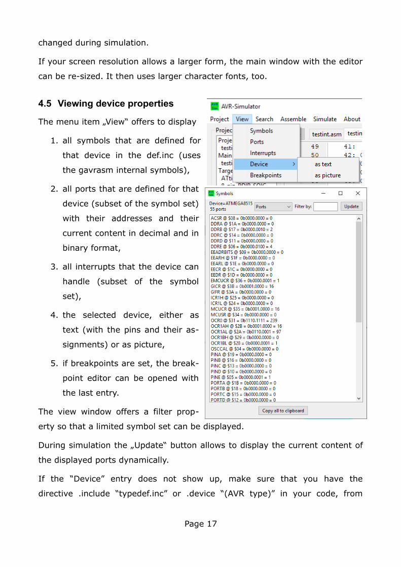
4.5 Viewing device properties
The menu item „View“ offers to display
1. all symbols that are defined for
that device in the def.inc (uses
the gavrasm internal symbols),
2. all ports that are defined for that
device (subset of the symbol set)
with their addresses and their
current content in decimal and in
binary format,
3. all interrupts that the device can
handle (subset of the symbol
set),
4. the selected device, either as
text (with the pins and their as-
signments) or as picture,
5. if breakpoints are set, the break-
point editor can be opened with
the last entry.
The view window offers a filter prop-
erty so that a limited symbol set can be displayed.
During simulation the „Update“ button allows to display the current content of
the displayed ports dynamically.
If the “Device” entry does not show up, make sure that you have the
directive .include “typedef.inc” or .device “(AVR type)” in your code, from
Page 17
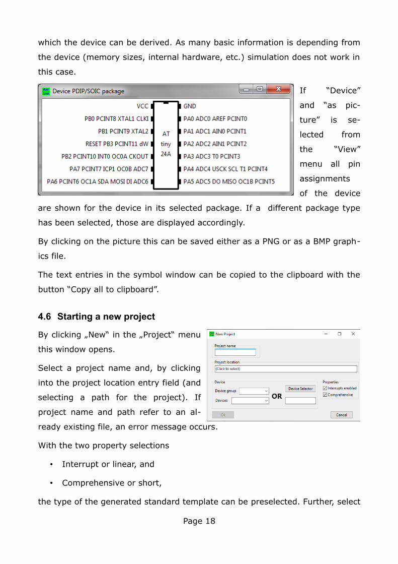
which the device can be derived. As many basic information is depending from
the device (memory sizes, internal hardware, etc.) simulation does not work in
this case.
If “Device”
and “as pic-
ture” is se-
lected from
the “View”
menu all pin
assignments
of the device
are shown for the device in its selected package. If a different package type
has been selected, those are displayed accordingly.
By clicking on the picture this can be saved either as a PNG or as a BMP graph-
ics file.
The text entries in the symbol window can be copied to the clipboard with the
button “Copy all to clipboard”.
4.6 Starting a new project
By clicking „New“ in the „Project“ menu
this window opens.
Select a project name and, by clicking
into the project location entry field (and
selecting a path for the project). If
project name and path refer to an al-
ready existing file, an error message occurs.
With the two property selections
• Interrupt or linear, and
• Comprehensive or short,
the type of the generated standard template can be preselected. Further, select
Page 18
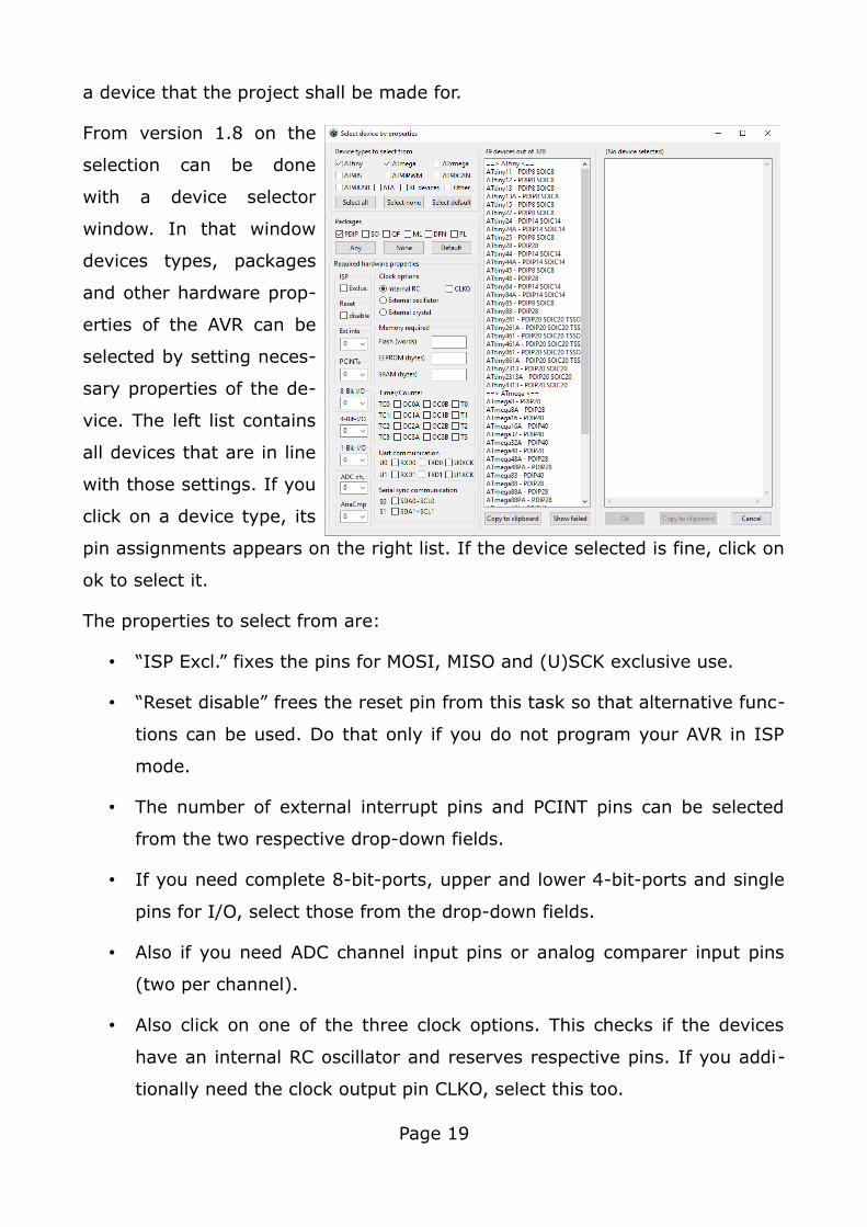
a device that the project shall be made for.
From version 1.8 on the
selection can be done
with a device selector
window. In that window
devices types, packages
and other hardware prop-
erties of the AVR can be
selected by setting neces-
sary properties of the de-
vice. The left list contains
all devices that are in line
with those settings. If you
click on a device type, its
pin assignments appears on the right list. If the device selected is fine, click on
ok to select it.
The properties to select from are:
• “ISP Excl.” fixes the pins for MOSI, MISO and (U)SCK exclusive use.
• “Reset disable” frees the reset pin from this task so that alternative func-
tions can be used. Do that only if you do not program your AVR in ISP
mode.
• The number of external interrupt pins and PCINT pins can be selected
from the two respective drop-down fields.
• If you need complete 8-bit-ports, upper and lower 4-bit-ports and single
pins for I/O, select those from the drop-down fields.
• Also if you need ADC channel input pins or analog comparer input pins
(two per channel).
• Also click on one of the three clock options. This checks if the devices
have an internal RC oscillator and reserves respective pins. If you addi-
tionally need the clock output pin CLKO, select this too.
Page 19
• If you need flash, EEPROM and/or SRAM memory of a certain size, input
these in the edit fields. Decimal as well as hexadecimal numbers (pre-
ceded by 0x or $) are accepted.
• Necessary pins for Timer/Counter output for TC0 to TC3 as well as input
pins T0 to T3 for the timers can also be selected.
• If you need asynchronous or synchronous serial communication, select
the necessary in- and output pins for that.
The list in the middle shows all device types that fulfill those hardware require-
ments in their respective package. The list can be copied to the clipboard. The
button “Show failed” opens a window with all devices that were excluded from
the list, with the main (and prioritized first) reason for exclusion. Package se-
lection lines can be removed with the button. This window also displays the se-
lection criteria in a short form. If you need these criteria, mark those lines and
copy those with Ctrl-C to the clipboard.
If a device is marked in the device list, its pin assignments appear in the win-
dow to the right. All pins that are assigned to one of the functions are listed
with their assignment and all alternative pin functions are removed. The as-
signed function is shown in lower-case characters, all unassigned pins remain
in capital letters. The window content can also be copied to the clipboard.
Clicking “Ok” selects the device, “Cancel” returns without selection. Both but-
tons close that window. This returns the control to the “New” dialog.
If you filled in all necessary details in the “New” dialog and error messages dis-
appear, press the OK button.
This opens the dialog for the package selection, if the selected device has more
than one available packages. The package dialog is described below.
The generated standard file can be edited, saved, assembled and simulated.
Page 20
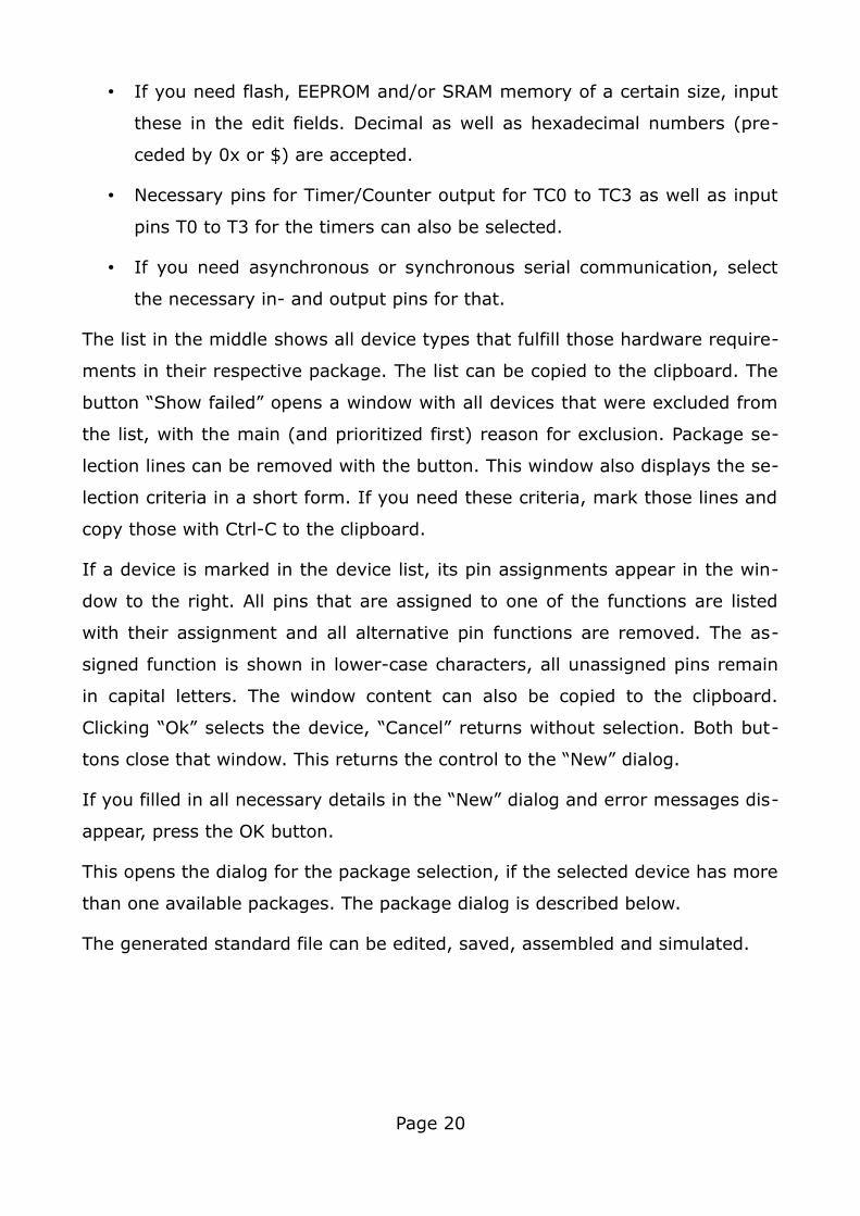
This is such a typical
source code file gen-
erated.
Note that if „Interrupts enabled“
and “Comprehensive” has been
chosen, the new file already holds
all reset and interrupt vectors of
the device.
4.7 Adding a new include file to an existing project
If a new include file shall be added place the cursor to the beginning of the line
where the include directive shall be added with the .include directive.
Then right-click with the mouse onto the editor field. Select “Add include” and,
in the opening dialog, a file name. The new file is generated in the folder where
the project resides. All included files that have an include directive entry (.in-
clude “[inc name]”) are recognized during the load process of the main file.
Those are added automatically to the tab entries and are directly accessible.
Excluded are *def.inc files which are used to identify the selected AVR type but
have no tab entry. Nested includes are possible to any depth.
Page 21
5 Assembling
5.1 Starting the assembly process
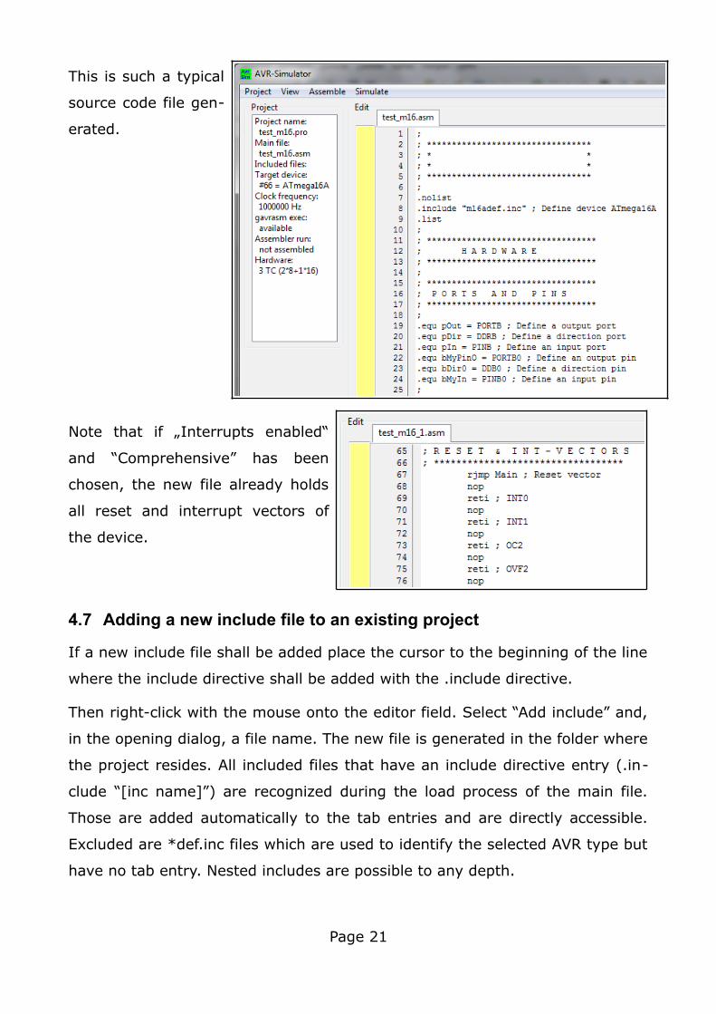
By pressing the menu item „Assemble“ the internal gavrasm assembles the
source file (and all associated include files). After gavrasm ended, a message
signals errors or success and the generated listing plus eventually the gener-
ated error file „.err“ is added to the editor tabs.
If you want to avoid the Warning 009: use the gavrasm-specific .device “[AVR
device” directive and remove the .nolist, the -.include “[device]def.inc” and the
.list directives. Note that this solution is incompatible with other assemblers. If
you want to use the simulator’s assembler gavrasm as well as other assem-
blers with the same source code file, then ask if a symbol with the device
name is defined (which gavrasm generates), then gavrasm is assembling. Use
Page 22
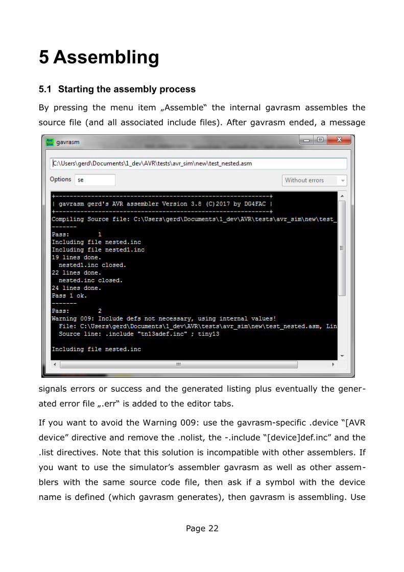
the following formulation to get it compatible in any case:
.ifdef ATmega8a ; defined if gavrasm is assembling
.device “ATmega8a” ; gavrasm is assembling
.else ; a different assembler is at work
.nolist
.include “m8adef.inc”
.list
.endif
If assembling found no errors, the list file is displayed in the editor window. If
you place the cursor into a line of the list file, the context menu offers to
change immediately to the line in the source file, where the list file entry re-
sults from.
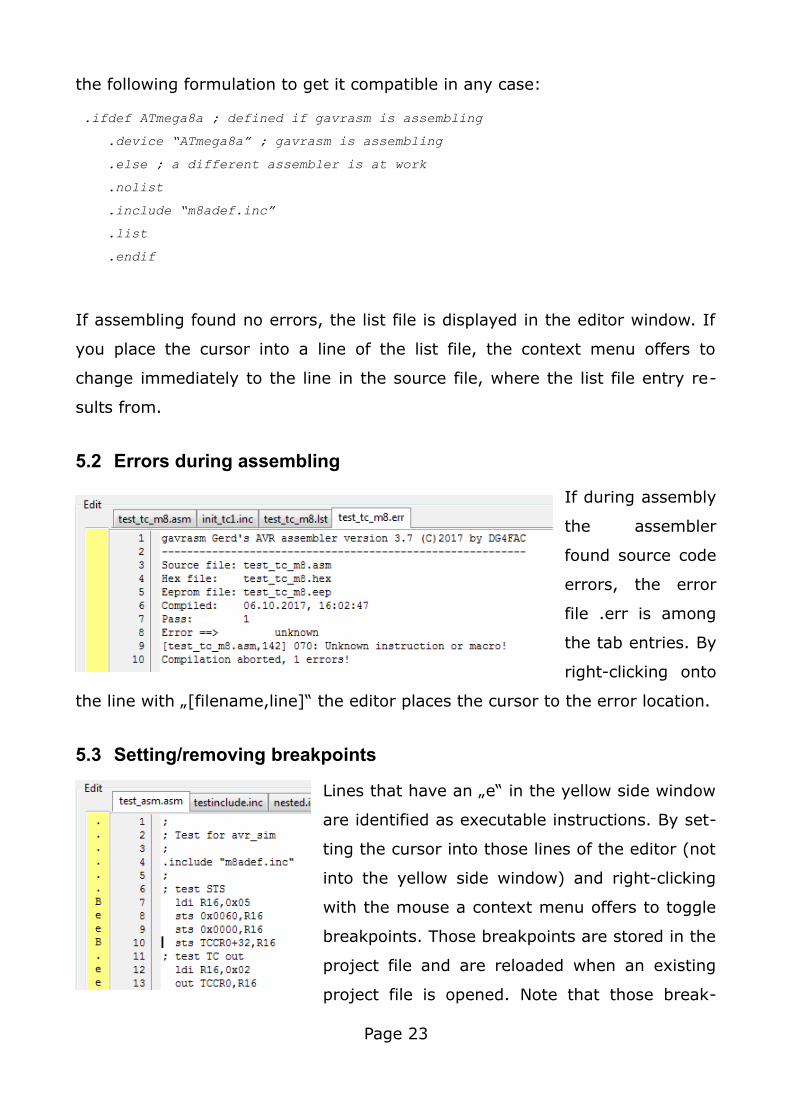
5.2 Errors during assembling
If during assembly
the assembler
found source code
errors, the error
file .err is among
the tab entries. By
right-clicking onto
the line with „[filename,line]“ the editor places the cursor to the error location.
5.3 Setting/removing breakpoints
Lines that have an „e“ in the yellow side window
are identified as executable instructions. By set-
ting the cursor into those lines of the editor (not
into the yellow side window) and right-clicking
with the mouse a context menu offers to toggle
breakpoints. Those breakpoints are stored in the
project file and are reloaded when an existing
project file is opened. Note that those break-
Page 23
points are only displayed after assembling the project.
Breakpoints are copied to the list file, that is also available as tab file following
assembling. In the list file breakpoints can be enabled and disabled as well,
those changes are copied to the original .asm and .inc files where they result
from.
Breakpoints can be changed “on the run” during an active simulation process
going on. The changes come immediately into effect.
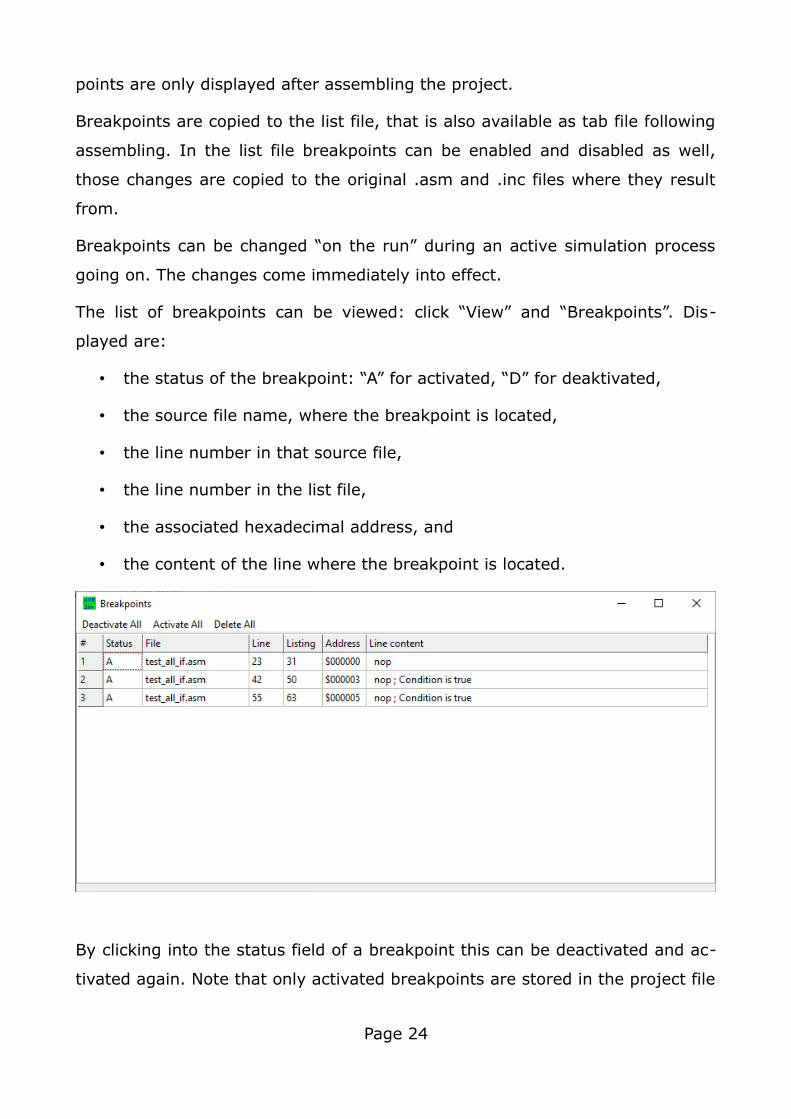
The list of breakpoints can be viewed: click “View” and “Breakpoints”. Dis-
played are:
• the status of the breakpoint: “A” for activated, “D” for deaktivated,
• the source file name, where the breakpoint is located,
• the line number in that source file,
• the line number in the list file,
• the associated hexadecimal address, and
• the content of the line where the breakpoint is located.
By clicking into the status field of a breakpoint this can be deactivated and ac-
tivated again. Note that only activated breakpoints are stored in the project file
Page 24
and are reloaded at project start.
Clicking into the number of the breakpoint (below the column header “#”)
deletes this breakpoint. Clicking into a breakpoint’s entry in the “Line” column
opens a dialog window that enables to move that breakpoint to another line in
the source code. Note that only lines that produce executable code (in the
source code file marked with an “e”, in the list file with a hexadecimal format-
ted instruction code). Erroneous setting to a different line throws an error mes-
sage and deactivates this breakpoint. Clicking onto one of the headers (except
for the line content) sorts the breakpoints by increasing content in that col-
umn.
The menu entries allow to activate (“Activate All”), deactivate (“Deactivate All”)
or delete (“Delete All”) all breakpoints. A maximum of 24 different breakpoints
can be handled.
All changes made come immediately in effect, even during a running simula-
tion.
When changes to the sources text are made, avr_sim tries to reflect those
changes, but the breakpoint allocation is not always correct. Following success-
ful re-assembling the breakpoints are checked. If errors occur the related
breakpoints are deactivated and can be manually corrected in the “View/Break-
points” window.
Page 25
6 Simulating
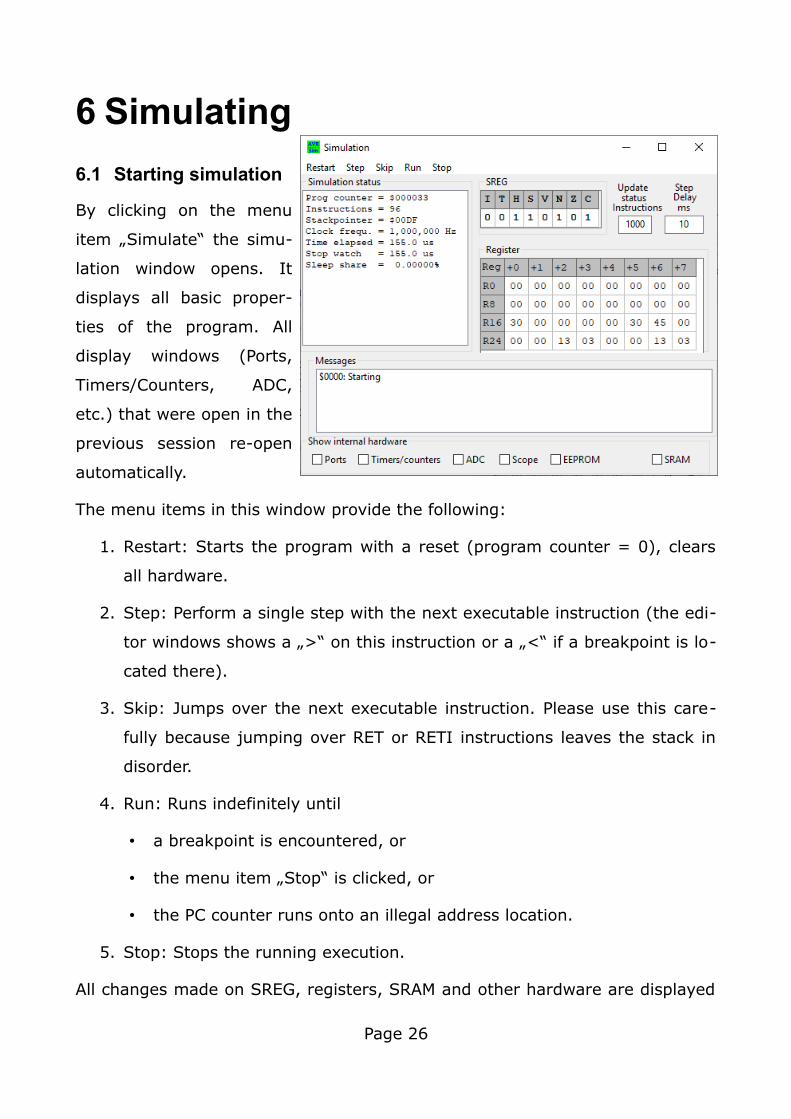
6.1 Starting simulation
By clicking on the menu
item „Simulate“ the simu-
lation window opens. It
displays all basic proper-
ties of the program. All
display windows (Ports,
Timers/Counters, ADC,
etc.) that were open in the
previous session re-open
automatically.
The menu items in this window provide the following:
1. Restart: Starts the program with a reset (program counter = 0), clears
all hardware.
2. Step: Perform a single step with the next executable instruction (the edi-
tor windows shows a „>“ on this instruction or a „<“ if a breakpoint is lo-
cated there).
3. Skip: Jumps over the next executable instruction. Please use this care-
fully because jumping over RET or RETI instructions leaves the stack in
disorder.
4. Run: Runs indefinitely until
• a breakpoint is encountered, or
• the menu item „Stop“ is clicked, or
• the PC counter runs onto an illegal address location.
5. Stop: Stops the running execution.
All changes made on SREG, registers, SRAM and other hardware are displayed
Page 26
during execution. Performing a single step clears all those marked changes.
The content of the registers can be manipulated by entering hexadecimal num-
bers into the register fields, followed by the return key. Only valid hex numbers
are accepted. Note that re-setting the simulation clears all register content.
In interrupt-controlled operating modes the share of SLEEP instructions per-
formed is displayed if at least one instruction has been performed.
Elapsed time, the stop watch and the SLEEP share are cleared if a right-click is
made on those entries. Please not that clearing elapsed time also clears the
scope event storage.
The edit field allows to input the number of instructions that trigger an update
to the display if a Run is active. Smaller numbers increase display update
speed, but also increase the time that is needed for simulation. The entry can
be changed on the fly and comes immediately into effect.
The edit field “Step delay” allows to add extra time to each simulation step
when running by setting it to numbers above 10 ms. Changes come into effect
immediately.
The message window provides information on unimplemented or illegal instruc-
tions. Identical messages at the same program counter address are displayed
only once.
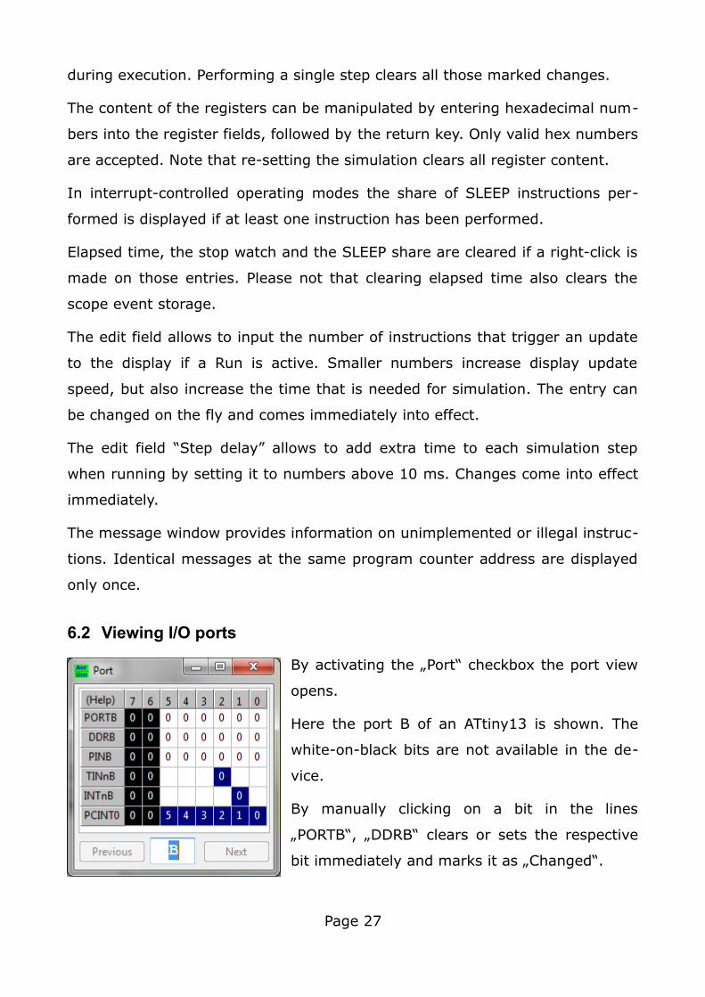
6.2 Viewing I/O ports
By activating the „Port“ checkbox the port view
opens.
Here the port B of an ATtiny13 is shown. The
white-on-black bits are not available in the de-
vice.
By manually clicking on a bit in the lines
„PORTB“, „DDRB“ clears or sets the respective
bit immediately and marks it as „Changed“.
Page 27
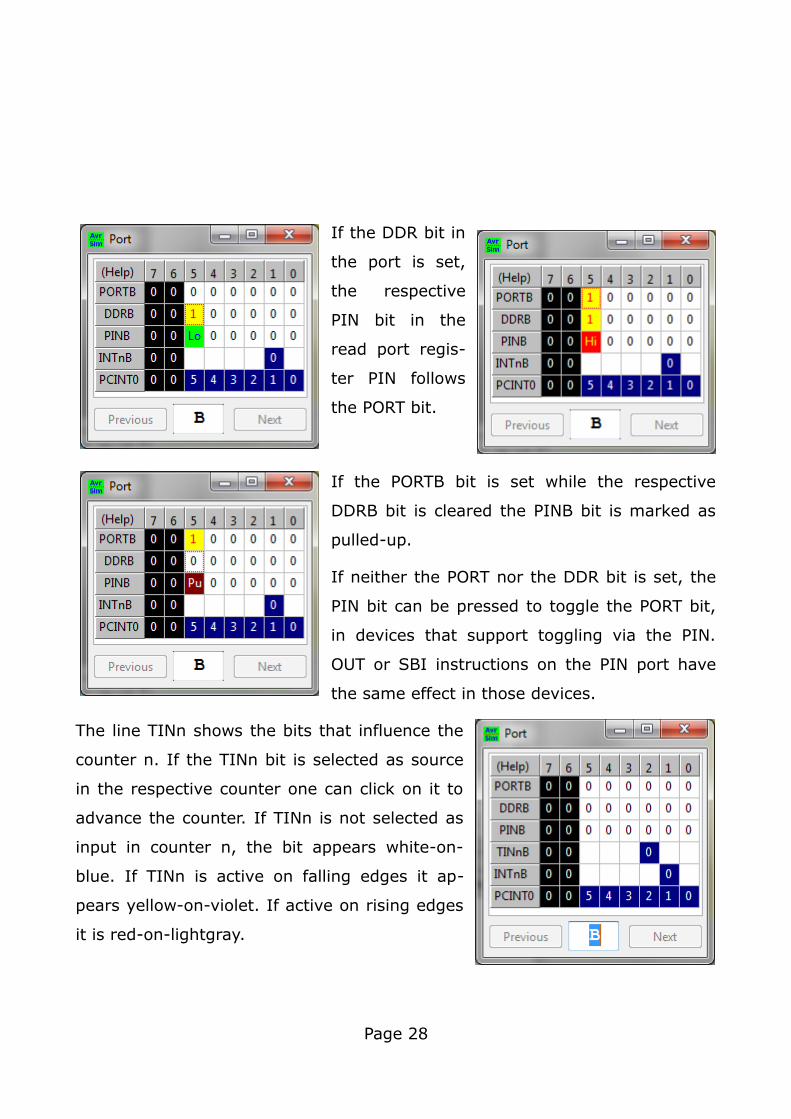
If the DDR bit in
the port is set,
the respective
PIN bit in the
read port regis-
ter PIN follows
the PORT bit.
If the PORTB bit is set while the respective
DDRB bit is cleared the PINB bit is marked as
pulled-up.
If neither the PORT nor the DDR bit is set, the
PIN bit can be pressed to toggle the PORT bit,
in devices that support toggling via the PIN.
OUT or SBI instructions on the PIN port have
the same effect in those devices.
The line TINn shows the bits that influence the
counter n. If the TINn bit is selected as source
in the respective counter one can click on it to
advance the counter. If TINn is not selected as
input in counter n, the bit appears white-on-
blue. If TINn is active on falling edges it ap-
pears yellow-on-violet. If active on rising edges
it is red-on-lightgray.
Page 28
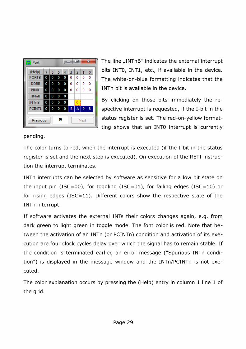
The line „INTnB“ indicates the external interrupt
bits INT0, INT1, etc., if available in the device.
The white-on-blue formatting indicates that the
INTn bit is available in the device.
By clicking on those bits immediately the re-
spective interrupt is requested, if the I-bit in the
status register is set. The red-on-yellow format-
ting shows that an INT0 interrupt is currently
pending.
The color turns to red, when the interrupt is executed (if the I bit in the status
register is set and the next step is executed). On execution of the RETI instruc-
tion the interrupt terminates.
INTn interrupts can be selected by software as sensitive for a low bit state on
the input pin (ISC=00), for toggling (ISC=01), for falling edges (ISC=10) or
for rising edges (ISC=11). Different colors show the respective state of the
INTn interrupt.
If software activates the external INTs their colors changes again, e.g. from
dark green to light green in toggle mode. The font color is red. Note that be-
tween the activation of an INTn (or PCINTn) condition and activation of its exe-
cution are four clock cycles delay over which the signal has to remain stable. If
the condition is terminated earlier, an error message (“Spurious INTn condi-
tion”) is displayed in the message window and the INTn/PCINTn is not exe-
cuted.
The color explanation occurs by pressing the (Help) entry in column 1 line 1 of
the grid.
Page 29
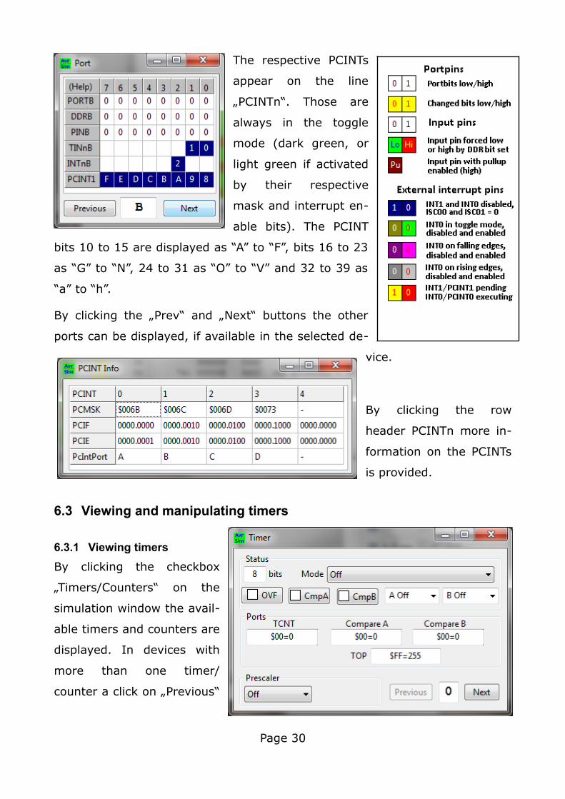
The respective PCINTs
appear on the line
„PCINTn“. Those are
always in the toggle
mode (dark green, or
light green if activated
by their respective
mask and interrupt en-
able bits). The PCINT
bits 10 to 15 are displayed as “A” to “F”, bits 16 to 23
as “G” to “N”, 24 to 31 as “O” to “V” and 32 to 39 as
“a” to “h”.
By clicking the „Prev“ and „Next“ buttons the other
ports can be displayed, if available in the selected de-
vice.
By clicking the row
header PCINTn more in-
formation on the PCINTs
is provided.
6.3 Viewing and manipulating timers
6.3.1 Viewing timers
By clicking the checkbox
„Timers/Counters“ on the
simulation window the avail-
able timers and counters are
displayed. In devices with
more than one timer/
counter a click on „Previous“
Page 30
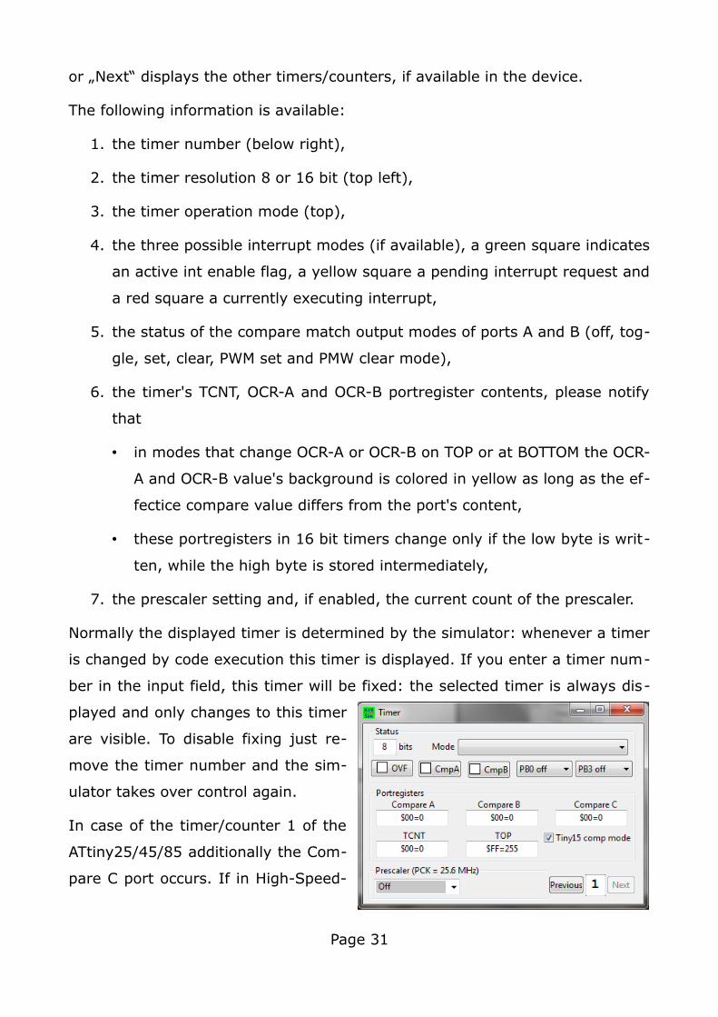
or „Next“ displays the other timers/counters, if available in the device.
The following information is available:
1. the timer number (below right),
2. the timer resolution 8 or 16 bit (top left),
3. the timer operation mode (top),
4. the three possible interrupt modes (if available), a green square indicates
an active int enable flag, a yellow square a pending interrupt request and
a red square a currently executing interrupt,
5. the status of the compare match output modes of ports A and B (off, tog-
gle, set, clear, PWM set and PMW clear mode),
6. the timer's TCNT, OCR-A and OCR-B portregister contents, please notify
that
• in modes that change OCR-A or OCR-B on TOP or at BOTTOM the OCR-
A and OCR-B value's background is colored in yellow as long as the ef-
fectice compare value differs from the port's content,
• these portregisters in 16 bit timers change only if the low byte is writ-
ten, while the high byte is stored intermediately,
7. the prescaler setting and, if enabled, the current count of the prescaler.
Normally the displayed timer is determined by the simulator: whenever a timer
is changed by code execution this timer is displayed. If you enter a timer num-
ber in the input field, this timer will be fixed: the selected timer is always dis-
played and only changes to this timer
are visible. To disable fixing just re-
move the timer number and the sim-
ulator takes over control again.
In case of the timer/counter 1 of the
ATtiny25/45/85 additionally the Com-
pare C port occurs. If in High-Speed-
Page 31
Mode (PLL switched on) the check field for Tiny15 compatibility mode occurs
which alters the PLL frequency. The prescaler field shows the frequency of the
source.
6.3.2 Changing timer values
In the Timer/Counter view the following items can be changed:
1. The values of TCCNT, Compare A, B, C and ICR can be changed if avail-
able in the device. Just click into the respective edit field, enter either
hexadecimal (preceded by a $, A to F in small or capital letters) or deci-
mal numbers and hit the return key. In case of an error (unreadable
number or number larger than allowed) the edit field turns red. The val-
ues entered change the respective port register values immediately, but
in case of the compare values A, B and ICR those might get effective
only later on if the counter reaches TOP, MAX or BOTTOM, depending
from the selected operation mode of the timer/counter.
2. The value of the prescaler. Just select the desired entry from the drop-
down field. Note that manually entered changes in the text field are ig-
nored.
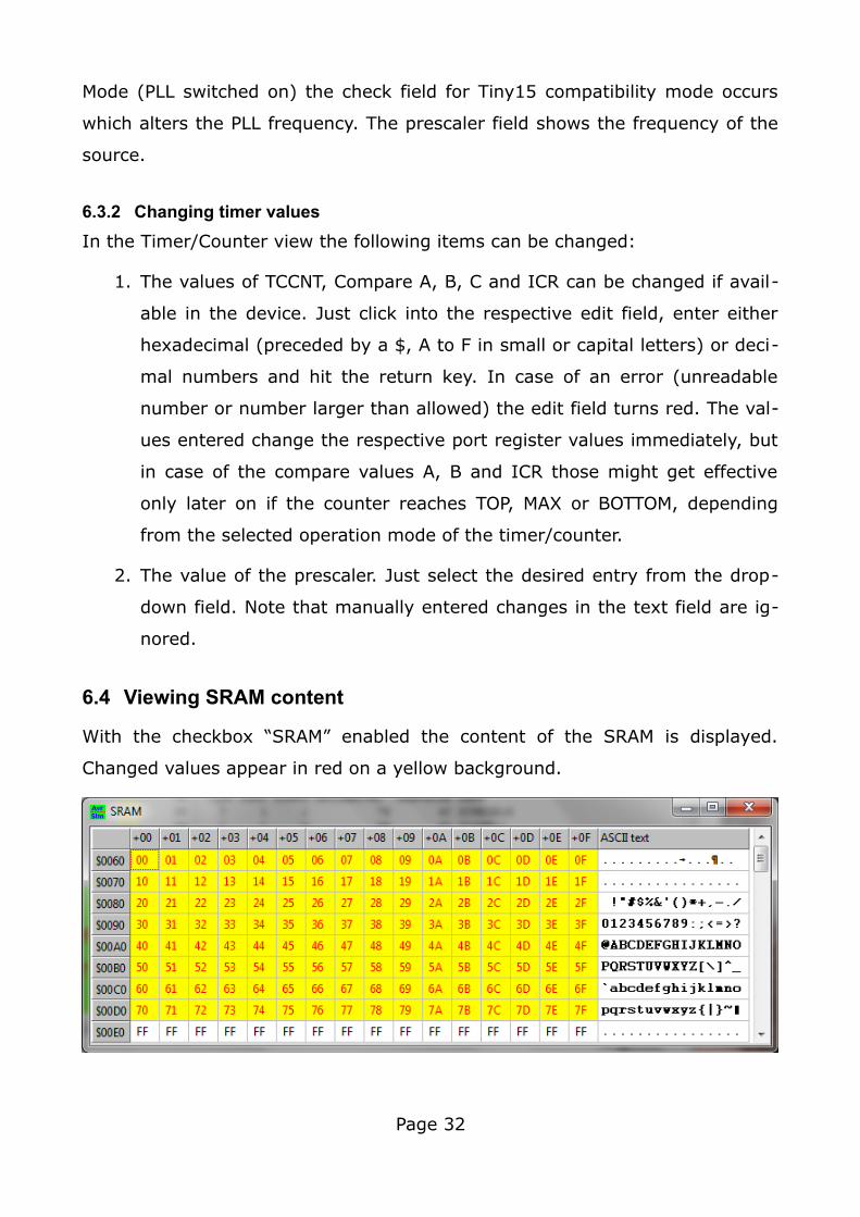
6.4 Viewing SRAM content
With the checkbox “SRAM” enabled the content of the SRAM is displayed.
Changed values appear in red on a yellow background.
Page 32
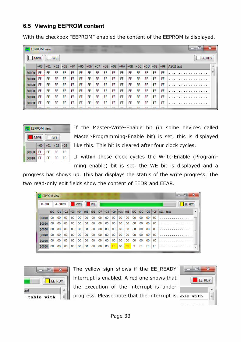
6.5 Viewing EEPROM content
With the checkbox “EEPROM” enabled the content of the EEPROM is displayed.
If the Master-Write-Enable bit (in some devices called
Master-Programming-Enable bit) is set, this is displayed
like this. This bit is cleared after four clock cycles.
If within these clock cycles the Write-Enable (Program-
ming enable) bit is set, the WE bit is displayed and a
progress bar shows up. This bar displays the status of the write progress. The
two read-only edit fields show the content of EEDR and EEAR.
The yellow sign shows if the EE_READY
interrupt is enabled. A red one shows that
the execution of the interrupt is under
progress. Please note that the interrupt is
Page 33
repeated as long as the interrupt enable bit in EECR is set and as no EEPROM
write is going on.
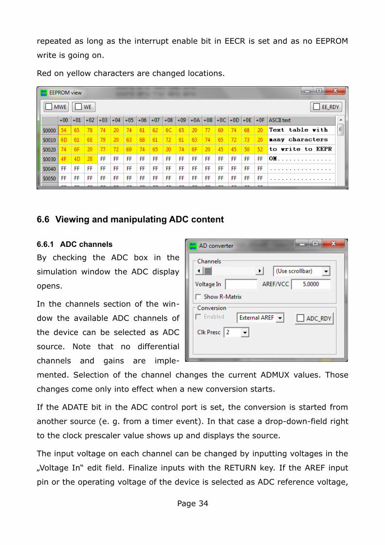
Red on yellow characters are changed locations.
6.6 Viewing and manipulating ADC content
6.6.1 ADC channels
By checking the ADC box in the
simulation window the ADC display
opens.
In the channels section of the win-
dow the available ADC channels of
the device can be selected as ADC
source. Note that no differential
channels and gains are imple-
mented. Selection of the channel changes the current ADMUX values. Those
changes come only into effect when a new conversion starts.
If the ADATE bit in the ADC control port is set, the conversion is started from
another source (e. g. from a timer event). In that case a drop-down-field right
to the clock prescaler value shows up and displays the source.
The input voltage on each channel can be changed by inputting voltages in the
„Voltage In“ edit field. Finalize inputs with the RETURN key. If the AREF input
pin or the operating voltage of the device is selected as ADC reference voltage,
Page 34
the respective voltage can be changed in the AREF/VCC edit field. All voltages
can be saved and are stored in the project file and are reloaded when the
project file is reloaded.
The results of the conversion are displayed in the read-only editor fields ADCH
and ADCL.
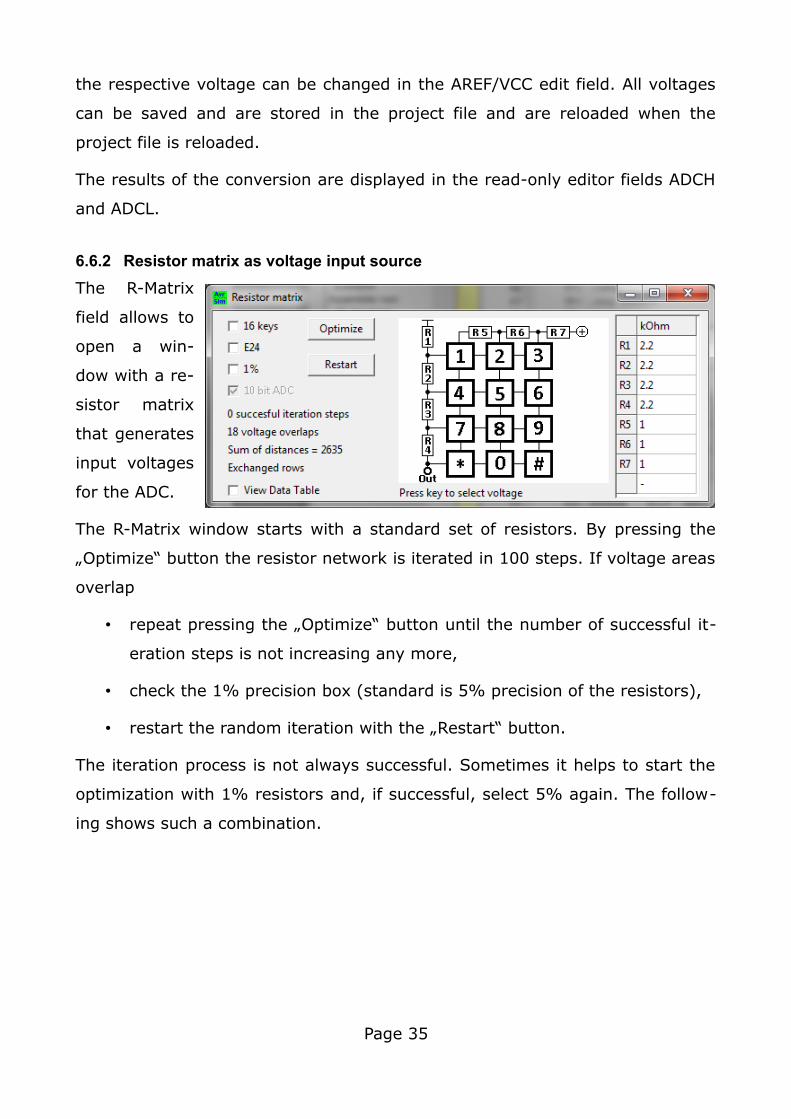
6.6.2 Resistor matrix as voltage input source
The R-Matrix
field allows to
open a win-
dow with a re-
sistor matrix
that generates
input voltages
for the ADC.
The R-Matrix window starts with a standard set of resistors. By pressing the
„Optimize“ button the resistor network is iterated in 100 steps. If voltage areas
overlap
• repeat pressing the „Optimize“ button until the number of successful it-
eration steps is not increasing any more,
• check the 1% precision box (standard is 5% precision of the resistors),
• restart the random iteration with the „Restart“ button.
The iteration process is not always successful. Sometimes it helps to start the
optimization with 1% resistors and, if successful, select 5% again. The follow-
ing shows such a combination.
Page 35
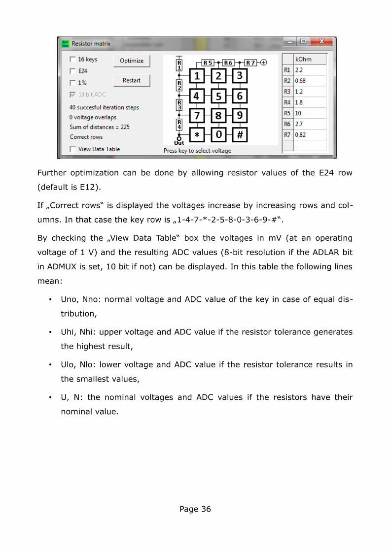
Further optimization can be done by allowing resistor values of the E24 row
(default is E12).
If „Correct rows“ is displayed the voltages increase by increasing rows and col-
umns. In that case the key row is „1-4-7-*-2-5-8-0-3-6-9-#“.
By checking the „View Data Table“ box the voltages in mV (at an operating
voltage of 1 V) and the resulting ADC values (8-bit resolution if the ADLAR bit
in ADMUX is set, 10 bit if not) can be displayed. In this table the following lines
mean:
• Uno, Nno: normal voltage and ADC value of the key in case of equal dis-
tribution,
• Uhi, Nhi: upper voltage and ADC value if the resistor tolerance generates
the highest result,
• Ulo, Nlo: lower voltage and ADC value if the resistor tolerance results in
the smallest values,
• U, N: the nominal voltages and ADC values if the resistors have their
nominal value.
Page 36
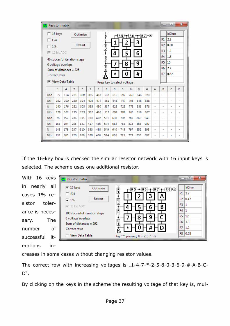
If the 16-key box is checked the similar resistor network with 16 input keys is
selected. The scheme uses one additional resistor.
With 16 keys
in nearly all
cases 1% re-
sistor toler-
ance is neces-
sary. The
number of
successful it-
erations in-
creases in some cases without changing resistor values.
The correct row with increasing voltages is „1-4-7-*-2-5-8-0-3-6-9-#-A-B-C-
D“.
By clicking on the keys in the scheme the resulting voltage of that key is, mul-
Page 37
tiplied by the VCC voltage, transferred to the ADC input voltage edit field.
6.6.3 Active AD conversion
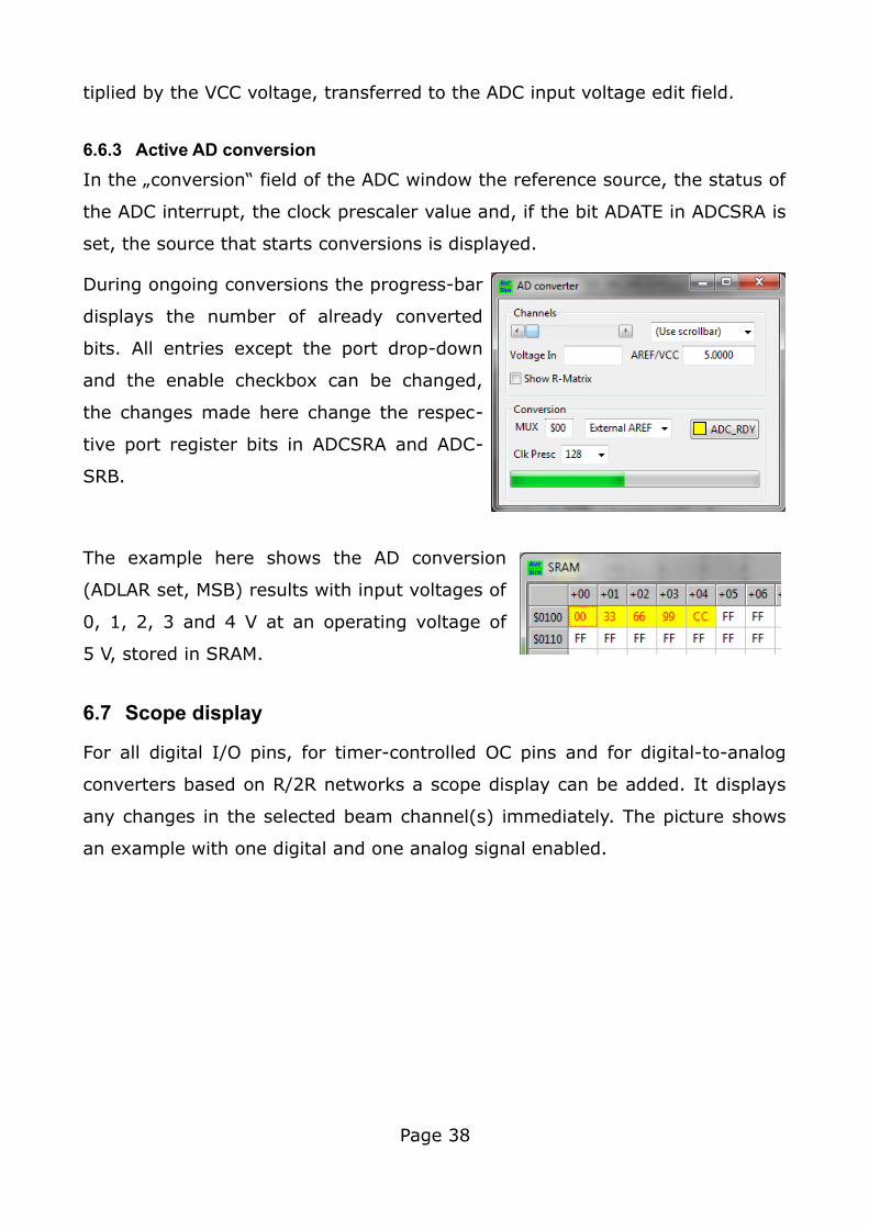
In the „conversion“ field of the ADC window the reference source, the status of
the ADC interrupt, the clock prescaler value and, if the bit ADATE in ADCSRA is
set, the source that starts conversions is displayed.
During ongoing conversions the progress-bar
displays the number of already converted
bits. All entries except the port drop-down
and the enable checkbox can be changed,
the changes made here change the respec-
tive port register bits in ADCSRA and ADC-
SRB.
The example here shows the AD conversion
(ADLAR set, MSB) results with input voltages of
0, 1, 2, 3 and 4 V at an operating voltage of
5 V, stored in SRAM.
6.7 Scope display
For all digital I/O pins, for timer-controlled OC pins and for digital-to-analog
converters based on R/2R networks a scope display can be added. It displays
any changes in the selected beam channel(s) immediately. The picture shows
an example with one digital and one analog signal enabled.
Page 38
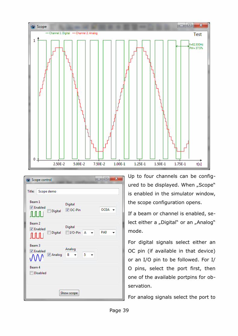
Up to four channels can be config-
ured to be displayed. When „Scope“
is enabled in the simulator window,
the scope configuration opens.
If a beam or channel is enabled, se-
lect either a „Digital“ or an „Analog“
mode.
For digital signals select either an
OC pin (if available in that device)
or an I/O pin to be followed. For I/
O pins, select the port first, then
one of the available portpins for ob-
servation.
For analog signals select the port to
Page 39
which the R/2R network is connected. From the available bits in this port select
the number of bits of the DAC (ranges from 2 to 8 if enough port bits are avail-
able in the selected port of the device).
Select the colors of the scope display for the channels by clicking on the small
windows below the „Enabled“ checkbox.
Input of the title is also required. If any one channel is selected and the title is
provided press „Show scope“ to open the scope display.
If you want to change the scope's properties during execution, stop the run-
ning execution and disable and enable „Scope“ again. Changes come into ef-
fect immediately, using the stored event data. If new channels have been
added, either click „Restart“ (the program restarts from scratch) or clear the
„Time elapsed“ in the status window (the event storage is cleared and starts
again without restarting program execution).
The displayed times are derived from „Time elapsed“ in the simulator window.
If this is cleared, or if simulation execution is restarted, the event storage is
cleared. Up to 1.000 events can be handled, beyond that an error message is
displayed.
Scope configuration is stored in the project's configuration file and is restored if
the project is re-loaded. The scope window then pops up automatically. If you
want to avoid that, open the scope control window, disable all beams and press
the “Discard” button. This clears the scope entries in the project file when clos-
ing the main window.
The displayed scope picture can be saved in PNG or BMP format by clicking on
it. Make sure that no Run is active.
Page 40
7 Not yet implemented, but under consideration
The following features are planned but are not yet implemented in the current
version, but are planned for future versions:
1. Manual changes to timer/counter modes are not yet implemented.
2. Devices with more than 128 kB flash memory are not yet implemented.
3. The AVR8 devices (ATtiny4 to 10) are not yet implemented.
4. ATxmega devices are implemented but no alternative pin functions are
assigned.
5. Older AVR types, such as the AT90S, are implemented, but are not yet
systematically tested for correct execution.
Page 41
8 Not implemented and not plannedThe following features are neither implemented nor planned:
1. Serial communication via Async Universial or Sync Serial modes is not
implemented and not planned.
2. Driving LCD displays is not and will not be implemented.
3. Those who generate enormous C code and convert it to even more volu-
minous asm source code will not be very happy with avr_sim and
gavrasm: from 10,000 lines of code on neither avr_sim nor gavrasm
work correct, just because the line numbers exceed their five-digit limit
and cause crashes and malfunctions. I do not plan to extend line num-
bers to whatever larger limit, instead I recommend: „Better learn a more
rational programming language instead of littering the world with ineffi-
cient and superfluous code lines!“.
Page 42
9 Changes introduced in version 1.9The following changes were introduced in this version.
9.1 Changes to the integrated assembler gavrasm
The internal assembler gavrasm was upgraded from version 4.5 to 4.6.
1. When using the term 1<<N, with an undefined value for N, the assem-
bler crashed. This has been corrected and replaced by an error message
(missing constant) in pass 2 of the assembler.
2. The terms 1<<N and 1>>N did not work correct for N>8, because of an
error in the FPC implementation of the SHL and SHR functions. In case of
N>8 the left-shifting was simply skipped after reaching 0x0100. This has
now been corrected, so that the range of N is not limited any more. In
case that the arithmetic range of INT64 is exceeded by left-shifting, a re-
spective error message occurs.
3. Support for the device types ATmega808/809/1608/1609 has been
added.
4. The error in the tn1634def.inc with the port registers OCR1BL/OCR1BH/
ICR1L/ICR1H has not been corrected in the latest Studio 7 version, so
the correction was made manually.
9.2 Changes concerning the editor
1. The editor and other components are now displayed only if a project is
activated.
2. All menu entries are now accessible via Ctrl keys. The associated keys
are displayed in the icons and, in sub-menus, by a text entry.
3. When marking text as block, overwrite did not work. A respective option
of the SynEdit component had not been set. This is now corrected.
4. When clicking on an error message in the .err file, the editor did not
Page 43
jump to the respective line in the source code. This is corrected.
5. The view of port registers under “View” and “Ports” was extended with a
binary representation of the content, to enable simpler identification of
certain port bits.
9.3 Changes concerning the simulator
1. All menu entries are now accessible with Ctrl keys, so that targeting of
the menu entry with the mouse is not necessary any more. The re-
spective Ctrl keys are displayed as icons.
2. Register content can be manipulated by entering hexadecimal numbers
into the respective register field, followed by the return key.
3. If a new project was generated with the options “Comprehensive” and
“Interrupts” enabled, the interrupt vectors were either not or falsely in-
serted in the source code (in parts caused by 3). This is corrected.
4. If a device with more than 32 kB of flash or more than 8 kB of SRAM
was defined, the enlarged memory sizes lead to a crash. This has been
fixed in this version.
5. Devices with more than 256 port registers crashed (too many portreg-
isters). This is corrected.
6. Devices with exactly 63 bytes EEPROM (ATtiny13) renamed the SREG
location, so the correct SREG port was not found. This could lead to se-
rious simulation faults if IN and OUT to SREG has been used.
7. The generation of a new project has been improved and errors were
fixed. So, e. g. the selection of the device type and package form had
been by-passed, which lead to an erroneous device type. The device
number is now displayed in two variations: Ni is the number of the in-
clude file *def.inc and points to the devices in the unit gavrdev, Np is
the number of the pin assignments of the devices and refers to the de-
vice groups in the unit avr_sim_deviceu.
8. The selection of devices with the device selector was buggy, so that
Page 44
several AVR types were not offered, even though those were correctly
implemented. (If you encounter this error in an older version, just edit
the .include line manually, save and reload the project.) The whole se-
lection algorithm has been improved and simplified (the unit avr_dev-
size has been removed and replaced by redundant information in the
unit gavrdev).
9. When selecting devices (menu “Project”, “New”, “Selector”) the row by
which 8-Bit I/O ports and INT pins are assigned was changed, so that
in an ATmega8515 four complete 8-bit I/O ports as well as INT2 could
be assigned, which is located in Port E.
10. Some older timer/counter hardware has been added. PWM2 in AT-
mega103 is added, PWM1B in ATtiny26 added.
11. Due to a programming bug the ADC reference voltage in devices with
only one reference bit (REFS0) had been set to 2.56 V and not to
1.1 V. This error has now been corrected.
12. The reason for a range check error when simulating larger devices has
been corrected.
13. The results of AD conversions now are displayed in the two small edit
fields ADCH and ADCL. Note that those are marked read-only, so man-
ual changes do not come into effect.
14. To allow simulation without any delay the delay input field has been
changed and can now be set to zero (as recommended by Michael Bel-
heur).
9.4 Changes of the handbook
1. The selection of device types and packages has been rewritten to reflect
the new opportunities in chapter 4.2.
Page 45
10 Known issuesThe Windows version, when used with a different screen resolution, does not
show sub-windows and their components as designed but incomplete. The rea-
son for this behavior is not understood by me. Hints on how this can be
avoided in the Lazarus environment are very welcome.
Even though I change the window designs in Linux I might have forgotten one
or two of these. If you want to make changes to the design use Lazarus and
the source code files.
Page 46