Embed Size (px)
Citation preview
SEA SYSTEMS S.R.L Control Panels, Push button panels and Prewired systems for lifts Street San Carlo 13 - 20010 Bareggio - Milano - ITALY Tel: +39 02 90 36 34 99 - Fax: +39 02 90 36 35 00 Internet: www.seasystems.it - e-mail: [email protected]
MSTK13-GB Rev.02 1/09/10
INSTALLATION AND USE
MANUAL
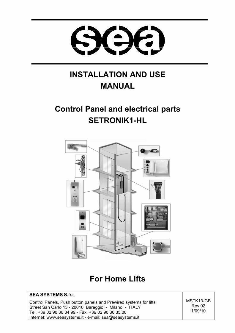
Control Panel and electrical parts SETRONIK1-HL
For Home Lifts
SEA SYSTEMS
INSTALLATION AND USE MANUAL Control Panel and electrical parts STK1-HL
For Home Lifts
MSTK13-GB Rev.02 1/09/10
SETRONIK1 Pagina 2 di 48
INTRODUCTION Our compliments for choosing the SETRONIK1-HL controller as the controller for your lift. Please carefully read this booklet so that you will be able to understand all the qualities of this device and its potential. The STK2-PM programmer allows to set a secret Access Code, know the conditions the lift is operating in, which and how many times failures and malfunctions have occurred, control the lift and doors motion and modify the operating characteristics of the lift itself. Several functions specific to a particular lift can be programmed without having to act on the Controller wiring. As far as the operating Diagnostics is concerned, help is provided by the failure and malfunction indications on the Programmer displays and by the indications supplied by the board LEDs.
WARNING Since our products are in constant evolution, all information contained in this manual can be modified by SEA SYSTEMS S.r.l. without notice. In the case of special lifts, any accessory documentation relating to additional or modified functions is provided..
SEA SYSTEMS
INSTALLATION AND USE MANUAL Control Panel and electrical parts STK1-HL
For Home Lifts
MSTK13-GB Rev.02 1/09/10
SETRONIK1 Pagina 3 di 48
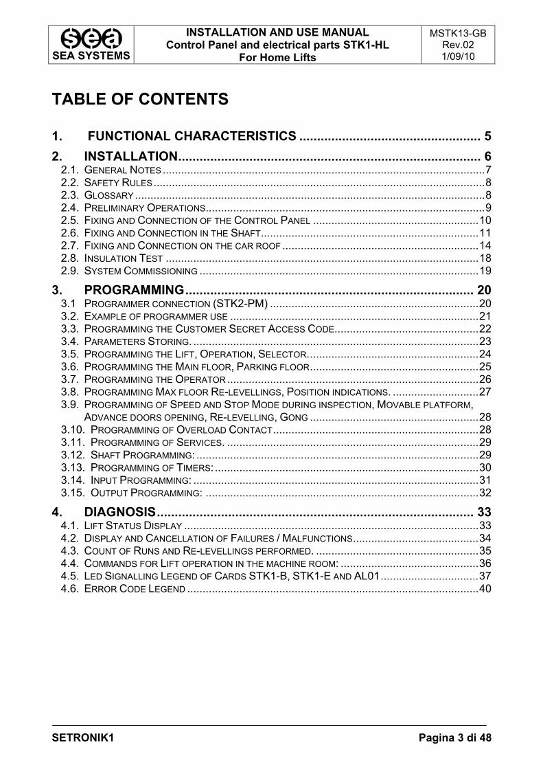
TABLE OF CONTENTS 1. FUNCTIONAL CHARACTERISTICS ................................................... 5
2. INSTALLATION..................................................................................... 6 2.1. GENERAL NOTES.........................................................................................................7 2.2. SAFETY RULES............................................................................................................8 2.3. GLOSSARY ..................................................................................................................8 2.4. PRELIMINARY OPERATIONS...........................................................................................9 2.5. FIXING AND CONNECTION OF THE CONTROL PANEL ......................................................10 2.6. FIXING AND CONNECTION IN THE SHAFT.......................................................................11 2.7. FIXING AND CONNECTION ON THE CAR ROOF ................................................................14 2.8. INSULATION TEST ......................................................................................................18 2.9. SYSTEM COMMISSIONING ...........................................................................................19
3. PROGRAMMING................................................................................. 20 3.1 PROGRAMMER CONNECTION (STK2-PM) ....................................................................20 3.2. EXAMPLE OF PROGRAMMER USE .................................................................................21 3.3. PROGRAMMING THE CUSTOMER SECRET ACCESS CODE...............................................22 3.4. PARAMETERS STORING. .............................................................................................23 3.5. PROGRAMMING THE LIFT, OPERATION, SELECTOR........................................................24 3.6. PROGRAMMING THE MAIN FLOOR, PARKING FLOOR.......................................................25 3.7. PROGRAMMING THE OPERATOR..................................................................................26 3.8. PROGRAMMING MAX FLOOR RE-LEVELLINGS, POSITION INDICATIONS. ............................27 3.9. PROGRAMMING OF SPEED AND STOP MODE DURING INSPECTION, MOVABLE PLATFORM,
ADVANCE DOORS OPENING, RE-LEVELLING, GONG .......................................................28 3.10. PROGRAMMING OF OVERLOAD CONTACT...................................................................28 3.11. PROGRAMMING OF SERVICES. ..................................................................................29 3.12. SHAFT PROGRAMMING: ............................................................................................29 3.13. PROGRAMMING OF TIMERS:......................................................................................30 3.14. INPUT PROGRAMMING: .............................................................................................31 3.15. OUTPUT PROGRAMMING: .........................................................................................32
4. DIAGNOSIS......................................................................................... 33 4.1. LIFT STATUS DISPLAY ................................................................................................33 4.2. DISPLAY AND CANCELLATION OF FAILURES / MALFUNCTIONS.........................................34 4.3. COUNT OF RUNS AND RE-LEVELLINGS PERFORMED. .....................................................35 4.4. COMMANDS FOR LIFT OPERATION IN THE MACHINE ROOM: .............................................36 4.5. LED SIGNALLING LEGEND OF CARDS STK1-B, STK1-E AND AL01................................37 4.6. ERROR CODE LEGEND ...............................................................................................40
SEA SYSTEMS
INSTALLATION AND USE MANUAL Control Panel and electrical parts STK1-HL
For Home Lifts
MSTK13-GB Rev.02 1/09/10
SETRONIK1 Pagina 4 di 48
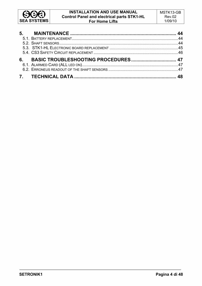
5. MAINTENANCE ................................................................................ 44 5.1. BATTERY REPLACEMENT.............................................................................................44 5.2. SHAFT SENSORS........................................................................................................44 5.3. STK1-HL ELECTRONIC BOARD REPLACEMENT ............................................................45 5.4. CS3 SAFETY CIRCUIT REPLACEMENT ..........................................................................46
6. BASIC TROUBLESHOOTING PROCEDURES.................................. 47 6.1. ALARMED CARD (ALL LED ON)....................................................................................47 6.2. ERRONEUS READOUT OF THE SHAFT SENSORS .............................................................47
7. TECHNICAL DATA ............................................................................. 48
SEA SYSTEMS
INSTALLATION AND USE MANUAL Control Panel and electrical parts STK1-HL
For Home Lifts
MSTK13-GB Rev.02 1/09/10
SETRONIK1 Pagina 5 di 48
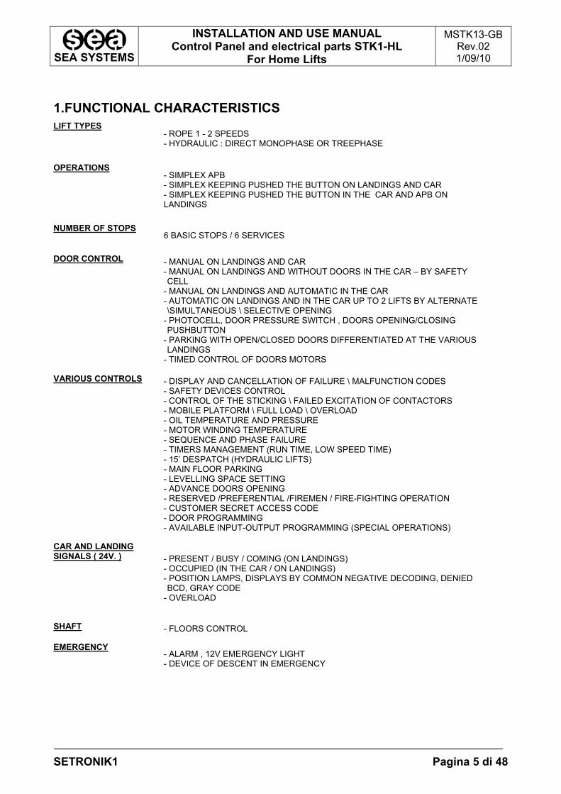
1.FUNCTIONAL CHARACTERISTICS LIFT TYPES
- ROPE 1 - 2 SPEEDS - HYDRAULIC : DIRECT MONOPHASE OR TREEPHASE
OPERATIONS
- SIMPLEX APB - SIMPLEX KEEPING PUSHED THE BUTTON ON LANDINGS AND CAR - SIMPLEX KEEPING PUSHED THE BUTTON IN THE CAR AND APB ON LANDINGS
NUMBER OF STOPS
6 BASIC STOPS / 6 SERVICES
DOOR CONTROL - MANUAL ON LANDINGS AND CAR
- MANUAL ON LANDINGS AND WITHOUT DOORS IN THE CAR – BY SAFETY CELL
- MANUAL ON LANDINGS AND AUTOMATIC IN THE CAR - AUTOMATIC ON LANDINGS AND IN THE CAR UP TO 2 LIFTS BY ALTERNATE \SIMULTANEOUS \ SELECTIVE OPENING
- PHOTOCELL, DOOR PRESSURE SWITCH , DOORS OPENING/CLOSING PUSHBUTTON
- PARKING WITH OPEN/CLOSED DOORS DIFFERENTIATED AT THE VARIOUS LANDINGS
- TIMED CONTROL OF DOORS MOTORS VARIOUS CONTROLS - DISPLAY AND CANCELLATION OF FAILURE \ MALFUNCTION CODES
- SAFETY DEVICES CONTROL - CONTROL OF THE STICKING \ FAILED EXCITATION OF CONTACTORS - MOBILE PLATFORM \ FULL LOAD \ OVERLOAD - OIL TEMPERATURE AND PRESSURE - MOTOR WINDING TEMPERATURE - SEQUENCE AND PHASE FAILURE - TIMERS MANAGEMENT (RUN TIME, LOW SPEED TIME) - 15’ DESPATCH (HYDRAULIC LIFTS) - MAIN FLOOR PARKING - LEVELLING SPACE SETTING - ADVANCE DOORS OPENING - RESERVED /PREFERENTIAL /FIREMEN / FIRE-FIGHTING OPERATION - CUSTOMER SECRET ACCESS CODE - DOOR PROGRAMMING - AVAILABLE INPUT-OUTPUT PROGRAMMING (SPECIAL OPERATIONS)
CAR AND LANDING SIGNALS ( 24V. )
- PRESENT / BUSY / COMING (ON LANDINGS) - OCCUPIED (IN THE CAR / ON LANDINGS) - POSITION LAMPS, DISPLAYS BY COMMON NEGATIVE DECODING, DENIED BCD, GRAY CODE
- OVERLOAD
SHAFT - FLOORS CONTROL EMERGENCY
- ALARM , 12V EMERGENCY LIGHT - DEVICE OF DESCENT IN EMERGENCY

SEA SYSTEMS
INSTALLATION AND USE MANUAL Control Panel and electrical parts STK1-HL
For Home Lifts
MSTK13-GB Rev.02 1/09/10
SETRONIK1 Pagina 6 di 48
2.INSTALLATION Fig.2.1. Pre-wiring Layout Drawing, including reference paragraphs for installation purposes
SHAFT: - Par. 2.6
CAR ROOF: - Par. 2.7
MACHINE ROOM: - Par. 2.5
SEA SYSTEMS
INSTALLATION AND USE MANUAL Control Panel and electrical parts STK1-HL
For Home Lifts
MSTK13-GB Rev.02 1/09/10
SETRONIK1 Pagina 7 di 48
2.1.GENERAL NOTES
NOTE Carefully read any warning information in the present operating instructions as
holding important safety, operating and service instructions. • Installation and service to be carried out in compliance with regulations in force, according to the manufacturer specifications and by authorised, trained and qualified personnel only.
• A wrong installation or an improper service could lead to damages to people, animals or objects, which the manufacturer is not liable for.
• Should the machine be sold or transferred to a different owner, check that the present operating instructions are always available, as to be duly used by the new owner or operator.
• Hereby listed documents are to be sued for a correct installation set-up: -Installation project drawing (not supplied by Sea); -Control Panel STK1: Installation and Maintenance Manual (this manual); -Control board programming and troubleshooting operating instructions; -Control Panel electric wiring; -Control Panel Installation electric wiring (in this manual).
•The installation manager must store any enclosed documents in a safe place, within reach, thus providing for a correct lift set-up and service. Operating instructions are an integral part to the installation and therefore they are not allowed to be damaged. Avoid tearing pages and when consulted, it is necessary to avoid damaging to provide for any possible future correct reference.
• Guarantee terms are on the product transportation document back. SEA SYSTEMS will support its products through the guarantee, in case of defects with a specified time period. Should the product not be correctly operated or its performance anyhow modified, differently from factory original specifications, the guarantee no longer applies.
• When necessary, get in touch with the company Service Department always providing for the installation serial number. The serial number is specified: - on the adhesive label on the outside of the control board unit; - On the first page of the board electric wiring; - On the Control board programming paper - On the Board Declaration of Conformity
• The serial number is to be always specified to identify the installation technical specifications. The safety department address and telephone number are available on the present operating instructions cover.
SEA SYSTEMS
INSTALLATION AND USE MANUAL Control Panel and electrical parts STK1-HL
For Home Lifts
MSTK13-GB Rev.02 1/09/10
SETRONIK1 Pagina 8 di 48
2.2.SAFETY RULES
•The unit can only be installed by qualified and authorised personnel, who is liable for the specific compliance to standards according to the technical best practice available.
•Before any cleaning or serve, cut the unit from the power supply by means of the installation cut-out switch.
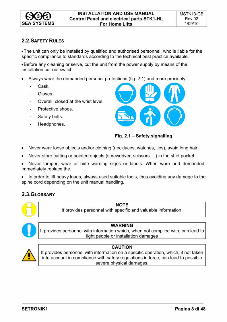
• Always wear the demanded personal protections (fig. 2.1),and more precisely: - Cask. - Gloves. - Overall, closed at the wrist level. - Protective shoes. - Safety belts. - Headphones.
Fig. 2.1 – Safety signalling • Never wear loose objects and/or clothing (necklaces, watches, ties), avoid long hair.
• Never store cutting or pointed objects (screwdriver, scissors …) in the shirt pocket.
• Never tamper, wear or hide warning signs or labels. When wore and demanded, immediately replace the.
• In order to lift heavy loads, always used suitable tools, thus avoiding any damage to the spine cord depending on the unit manual handling. 2.3.GLOSSARY
NOTE It provides personnel with specific and valuable information.
WARNING It provides personnel with information which, when not complied with, can lead to
light people or installation damages
CAUTION It provides personnel with information on a specific operation, which, if not taken into account in compliance with safety regulations in force, can lead to possible
severe physical damages.
SEA SYSTEMS
INSTALLATION AND USE MANUAL Control Panel and electrical parts STK1-HL
For Home Lifts
MSTK13-GB Rev.02 1/09/10
SETRONIK1 Pagina 9 di 48
2.4.PRELIMINARY OPERATIONS
Before starting the installation, check what follows: A)INSTALLATION PLACE SET UP
• Check the existing operating lighting.
• Check the unit and pit cleaning
• Check that the mains electric installation is connected to a suitable earthing (otherwise stop setting the installation up, until a suitable earthing or grounding is available).
• Check that the unit inlets are perfectly closed.
• A storage area next to the unit is to be available, easily accessible to operators and protected from any adverse weather condition.
• Check any cable tray and passing holes suitable for electric cabling, always to be easily inspected and well-refined.
B)MATERIAL UNLOADING AND WAREHOUSING
• Check the Control Panel specifications (Control Panel type, Contactors, Starting,…) must comply with demanded specifications on the order confirmation.
• Check the availability of any suitable material to be used during assembly, referring to the checklist accompanying the board documents.
• Check any unit and material condition when delivery to the site, to check possible damages which arrived during transportation. Immediately prevent SEA SYSTEMS Srl in the case of missing units or damages
• Store electric and electronic unit in a dry and cold room, in the original packaging.
• Should it not be possible, whatever reason, to immediately install the unit, periodically check stored units to avoid damages depending on a long storage under unfavourable conditions.
C)SCAFFOLDING
When setting the unit up, use standard scaffolding, exhibiting operating floors at any stop, at about 0.5 meter lower than the stop.
CAUTION Scaffolding completely or partially in metal, to be connected to a suitable
grounding, in compliance with safety regulations in force.
SEA SYSTEMS
INSTALLATION AND USE MANUAL Control Panel and electrical parts STK1-HL
For Home Lifts
MSTK13-GB Rev.02 1/09/10
SETRONIK1 Pagina 10 di 48
2.5.FIXING AND CONNECTION OF THE CONTROL PANEL
1. Drill the wall of the machine room, taking the locating holes of the angle bar provided as a reference, so that the height at which the panel hangs makes its use easy and convenient;
2. Anchor the angle bar to the upper section of the panel by means of appropriate bolts and cage nuts;
3. Fasten the angle bar to the wall of the machine room with corresponding wall plugs.
HIGHLIGHT Should the control panel be secured on premises other than the standard
machine room (ex: local cabinet, Pit, Shaft,...), the above procedure may be inappropriate. In this case, follow the instructions specified for the system.
4. Make sure that the QM master switch is set to OFF (DOWN position); 5. Connect the appliances to the control panel as per the installation diagrams in the
paragraph 2.8
SEA SYSTEMS
INSTALLATION AND USE MANUAL Control Panel and electrical parts STK1-HL
For Home Lifts
MSTK13-GB Rev.02 1/09/10
SETRONIK1 Pagina 11 di 48
2.6.FIXING AND CONNECTION IN THE SHAFT
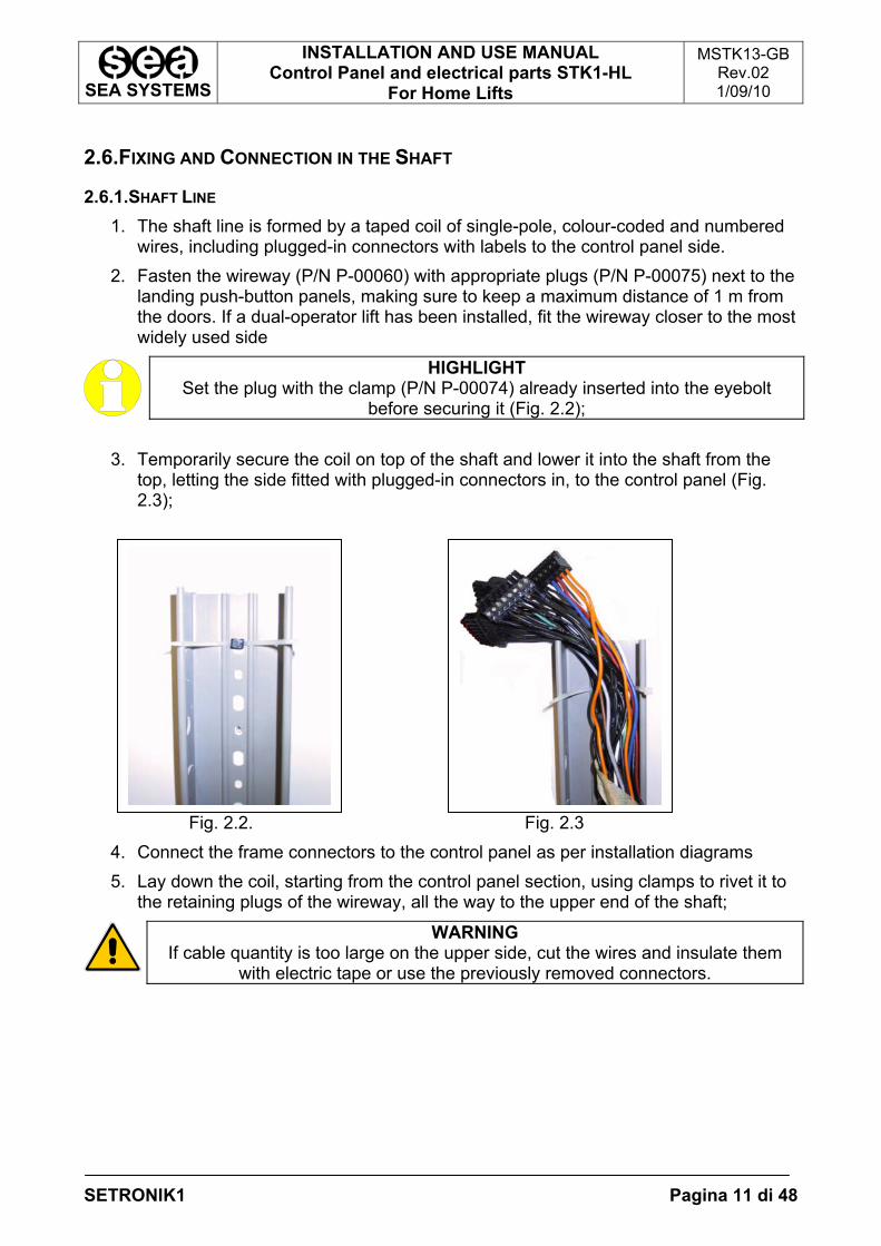
2.6.1.SHAFT LINE 1. The shaft line is formed by a taped coil of single-pole, colour-coded and numbered
wires, including plugged-in connectors with labels to the control panel side. 2. Fasten the wireway (P/N P-00060) with appropriate plugs (P/N P-00075) next to the
landing push-button panels, making sure to keep a maximum distance of 1 m from the doors. If a dual-operator lift has been installed, fit the wireway closer to the most widely used side
HIGHLIGHT Set the plug with the clamp (P/N P-00074) already inserted into the eyebolt
before securing it (Fig. 2.2);
3. Temporarily secure the coil on top of the shaft and lower it into the shaft from the top, letting the side fitted with plugged-in connectors in, to the control panel (Fig. 2.3);
Fig. 2.2. Fig. 2.3 4. Connect the frame connectors to the control panel as per installation diagrams 5. Lay down the coil, starting from the control panel section, using clamps to rivet it to
the retaining plugs of the wireway, all the way to the upper end of the shaft;
WARNING If cable quantity is too large on the upper side, cut the wires and insulate them
with electric tape or use the previously removed connectors.
SEA SYSTEMS
INSTALLATION AND USE MANUAL Control Panel and electrical parts STK1-HL
For Home Lifts
MSTK13-GB Rev.02 1/09/10
SETRONIK1 Pagina 12 di 48
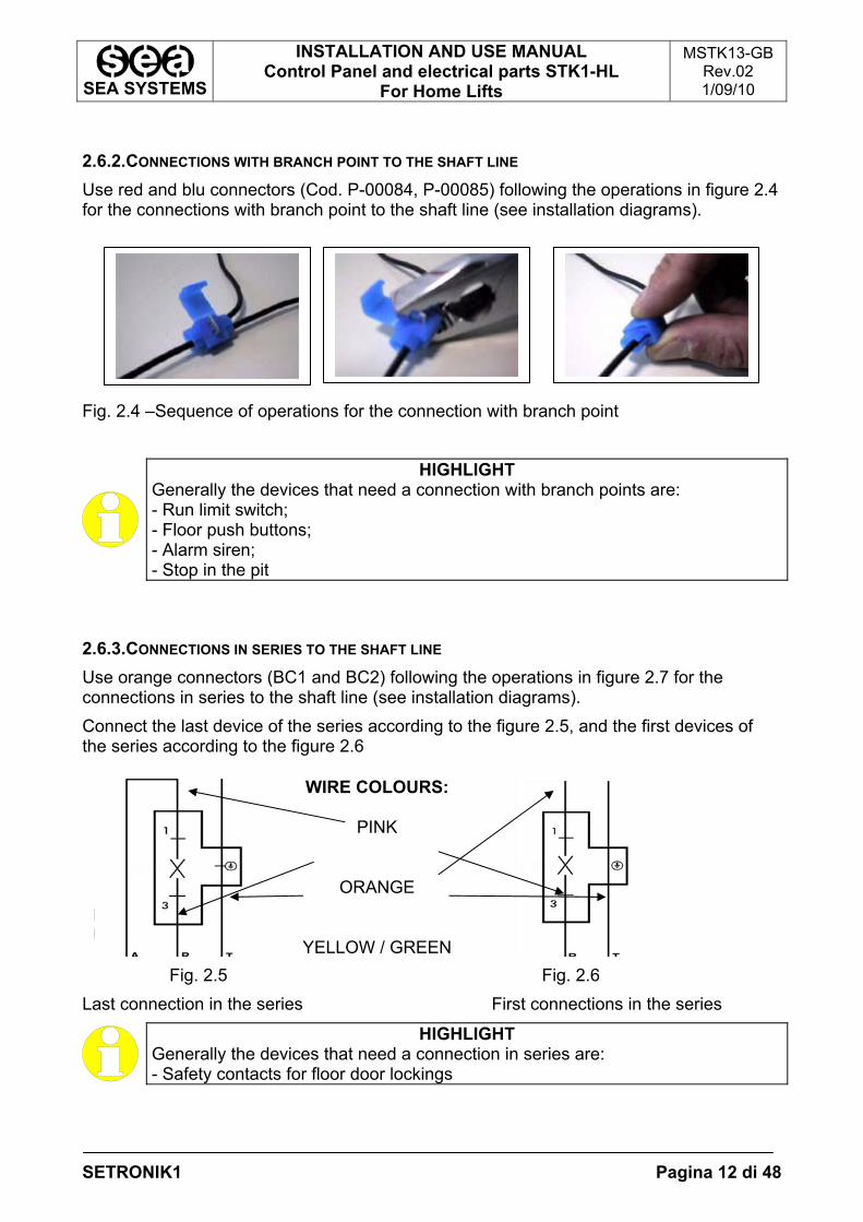
2.6.2.CONNECTIONS WITH BRANCH POINT TO THE SHAFT LINE Use red and blu connectors (Cod. P-00084, P-00085) following the operations in figure 2.4 for the connections with branch point to the shaft line (see installation diagrams). Fig. 2.4 –Sequence of operations for the connection with branch point
HIGHLIGHT Generally the devices that need a connection with branch points are: - Run limit switch; - Floor push buttons; - Alarm siren; - Stop in the pit
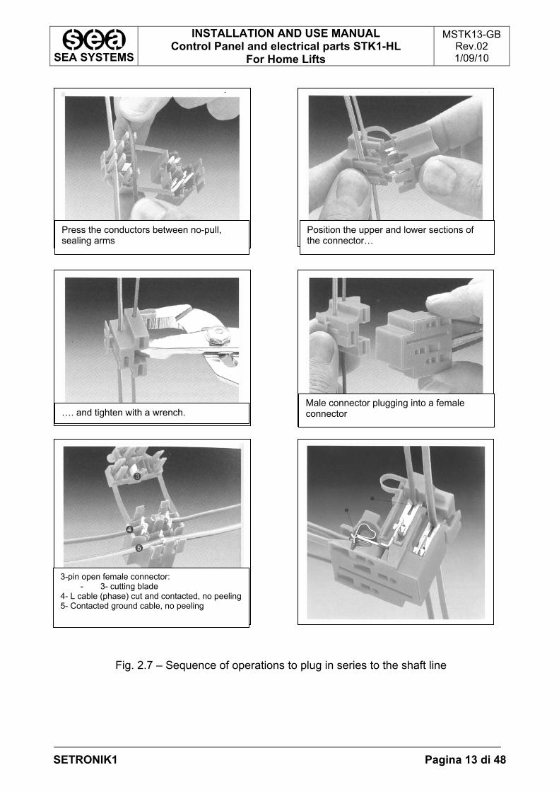
2.6.3.CONNECTIONS IN SERIES TO THE SHAFT LINE Use orange connectors (BC1 and BC2) following the operations in figure 2.7 for the connections in series to the shaft line (see installation diagrams). Connect the last device of the series according to the figure 2.5, and the first devices of the series according to the figure 2.6
Fig. 6.4.3Fig. 6.4.4 Upper End Landing ConnectorIntermediate Landings Connectors
Fig. 2.5 Fig. 2.6 Last connection in the series First connections in the series
HIGHLIGHT Generally the devices that need a connection in series are: - Safety contacts for floor door lockings
WIRE COLOURS:
PINK
ORANGE
YELLOW / GREEN
SEA SYSTEMS
INSTALLATION AND USE MANUAL Control Panel and electrical parts STK1-HL
For Home Lifts
MSTK13-GB Rev.02 1/09/10
SETRONIK1 Pagina 13 di 48
Fig. 2.7 – Sequence of operations to plug in series to the shaft line
Press the conductors between no-pull, sealing arms
Position the upper and lower sections of the connector…
…. and tighten with a wrench. Male connector plugging into a female connector
3-pin open female connector: - 3- cutting blade
4- L cable (phase) cut and contacted, no peeling 5- Contacted ground cable, no peeling
SEA SYSTEMS
INSTALLATION AND USE MANUAL Control Panel and electrical parts STK1-HL
For Home Lifts
MSTK13-GB Rev.02 1/09/10
SETRONIK1 Pagina 14 di 48
2.7.FIXING AND CONNECTION ON THE CAR ROOF
2.7.1.JUNCTION BOX FIXING AND FLEXIBLE CABLE CONNECTIONS: 1. Fasten the junction box with appropriate retaining screws; 2. Bring the flexible cables coil into the shaft pit; 3. Connect the flexible cables (ground side, with eyebolts) to the car box connectors as
per installation diagrams and secure them to the box with appropriate clamps (P/N P-00074);
4. Rivet the flexible cables to the car through the appropriate cable brackets (P/N P-00089) and plugs (P/N P-00102) on the roof and beneath the car (see fig. 2.1);
5. Connect the flexible cables (ground side, no eyebolts) to the control panel as per installation diagrams;
6. Fasten the wedge side bracket (P/N P-00086) to the shaft, about halfway, with appropriate plugs (P/N P-00102);
7. Anchor the flexible cables to the wedge side bracket in such a point that when the car has been lowered all the way down, the flexible cables box does not touch the bottom of the pit (see fig.2.1);
WARNING To solve the issue in connection with too big a box and too many flexible cables in the pit, shift the wedge side bracket upwards. Take into account that every time the bracket gets 1 meter higher, the box rises approximately by ½ meters.
8. Make sure that flexible cables are not entangled in the pit, otherwise, unplug the
connectors from the control panel, pull them straight and reconnect them; 9. Secure one of the cable brackets (P/N P-00089) to the pit wall, where flexible cables
start rising vertically along the shaft. 2.7.2.CAR PUSH BUTTON AND DOOR OPERATOR CONNECTION Connect the car push button and the operator according to the installation diagrams.
HIGHLIGHT In case it’s necessary to use the wireway (Cod. P-00087) to fit the cables on the car roof, fix it at the roof with screws (cod. P-00101)
SEA SYSTEMS
INSTALLATION AND USE MANUAL Control Panel and electrical parts STK1-HL
For Home Lifts
MSTK13-GB Rev.02 1/09/10
SETRONIK1 Pagina 15 di 48
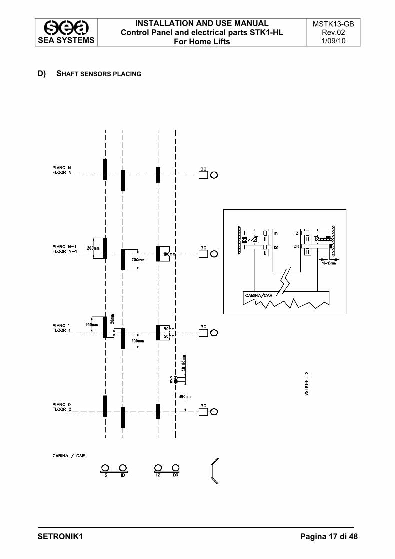
2.7.3.FIXING AND CONNECTION OF THE SHAFT SENSORS A) DESCRIPTION: It’s made with the following sensors: - bistable sensor DR for reset in downward - monostable sensor IS for stop and speed changing in upward - monostable sensor ID for stop and speed changing in downward - monostable sensor IZ for the safety circuit control B) FIXING AND CONNECTION OF THE SHAFT SENSORS:
1. Check the timer 4.12, for re-levelling zone, is set 0000. After done the following steps, it’s possible set a re-levelling zone explained al the paragraph 2.7.3.C.;
2. Fix the brackets with sensors IS, ID, IZ, DR on the car roof and the magnets directly on the guides as illustrated in the paragraph 2.7.3.C.
3. Connect the sensors according to the electric diagrams 4. Make some calls at the floors, going up and down verifying that the car stops with
the floor aligned at the landing floor.
HIGHLIGHT: Relevelling Zone Adjustment Should a levelling zone be required, follow the instructions in the Paragraph
2.7.3.C_Relevelling Zone Adjustment
SEA SYSTEMS
INSTALLATION AND USE MANUAL Control Panel and electrical parts STK1-HL
For Home Lifts
MSTK13-GB Rev.02 1/09/10
SETRONIK1 Pagina 16 di 48
C) RE-LEVELLING ZONE ADJUSTMENT FOR HYDRAULIC LIFTS
HIGHLIGHT: Relevelling Zone The Re-levelling Zone is the space in witch the car can move with open doors re-
levelling at the landing
1. Move down the IS magnet and move up the ID magnet. 2. Gradually increase the value of timer 4.12 so that, when upward and downward runs
are repeated, the car stops aligned with the floor sill. The timer value depends on the required speed and Re-levelling Zone.
WARNING The re-levelling control with open doors is permitted by the safety circuit (CS3 device and IS, ID, IZ sensors). When the led C and D of the CS3 device are on, the re-levelling control is permitted; if one or both of the leds are off the re-levelling control with open doors is interrupted.
SEA SYSTEMS
INSTALLATION AND USE MANUAL Control Panel and electrical parts STK1-HL
For Home Lifts
MSTK13-GB Rev.02 1/09/10
SETRONIK1 Pagina 17 di 48
D) SHAFT SENSORS PLACING
SEA SYSTEMS
INSTALLATION AND USE MANUAL Control Panel and electrical parts STK1-HL
For Home Lifts
MSTK13-GB Rev.02 1/09/10
SETRONIK1 Pagina 18 di 48
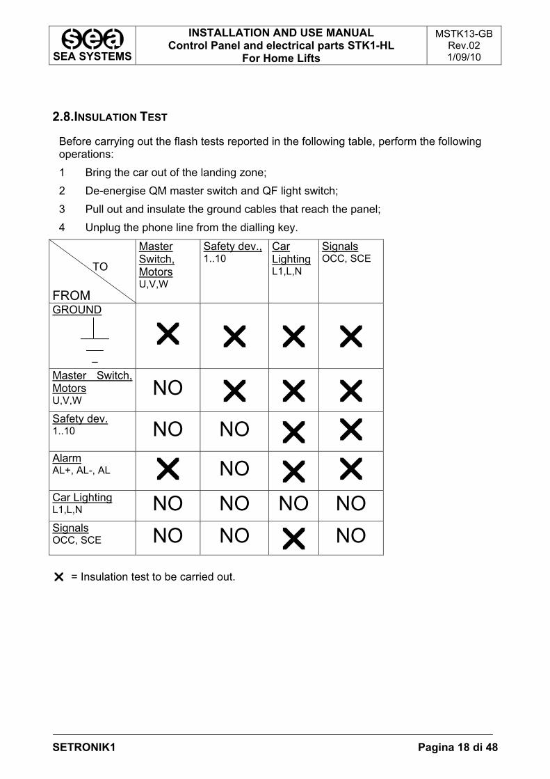
2.8.INSULATION TEST
Before carrying out the flash tests reported in the following table, perform the following operations: 1 Bring the car out of the landing zone; 2 De-energise QM master switch and QF light switch; 3 Pull out and insulate the ground cables that reach the panel; 4 Unplug the phone line from the dialling key.
TO FROM
Master Switch, Motors U,V,W
Safety dev., 1..10
Car Lighting L1,L,N
Signals OCC, SCE
GROUND _____ ___ _
Master Switch, Motors U,V,W
NO
Safety dev. 1..10 NO NO
Alarm AL+, AL-, AL NO
Car Lighting L1,L,N NO NO NO NOSignals OCC, SCE NO NO NO = Insulation test to be carried out.
SEA SYSTEMS
INSTALLATION AND USE MANUAL Control Panel and electrical parts STK1-HL
For Home Lifts
MSTK13-GB Rev.02 1/09/10
SETRONIK1 Pagina 19 di 48
2.9.SYSTEM COMMISSIONING
1. Turn ON the control panel and ascertain that the following leds are switched ON: 1, 2, 8, 10, CM, 01, +5 (in case of Hydraulic lift also TC);
2. Should any problems arise (ex: alarmed card: ALL leds ON), refer to Paragraph 6: Basic Troubleshooting Procedures.

SEA SYSTEMS
INSTALLATION AND USE MANUAL Control Panel and electrical parts STK1-HL
For Home Lifts
MSTK13-GB Rev.02 1/09/10
SETRONIK1 Pagina 20 di 48
3.PROGRAMMING 3.1PROGRAMMER CONNECTION (STK2-PM)
1. Check that the ON\OFF switch of the Keyboard is in the OFF position. 2. Insert the connection cable in connector FC3 on the STK1-HL board. 3. Bring the ON\OFF switch in the ON position. 4. All the 7 displays show the number 8 for about 2”: this function is used to check that
all displays are working correctly. 5. After the 2”, the displays show 0.00.XXXX (X indicates any number), or 0.00.0000
with the last four digits flashing. In this second case it means that an access code has been stored and that it is therefore necessary to enter the digits of the access code in the last 4 displays (DG3..DG6) and then to press .
A b
D e f g c a= Displays indicating the Parameter Code, marked as DG0, DG1 and DG2. b= Displays indicating the Parameter Value, marked DG3, DG4, DG5, DG6. c= DIN guide release d= ON\OFF switch. e= Connection cable to connector FC3 on the STK1-HL board. f= Pushbutton to select the display from DG0 to DG6, scrolling from left to right
whenever it is pressed. The selected display flashes. g= Pushbuttons , to modify the number of the display previously selected. (Please refer to ‘Example of programmer use’ Par. 3.2)
SEA SYSTEMS
INSTALLATION AND USE MANUAL Control Panel and electrical parts STK1-HL
For Home Lifts
MSTK13-GB Rev.02 1/09/10
SETRONIK1 Pagina 21 di 48
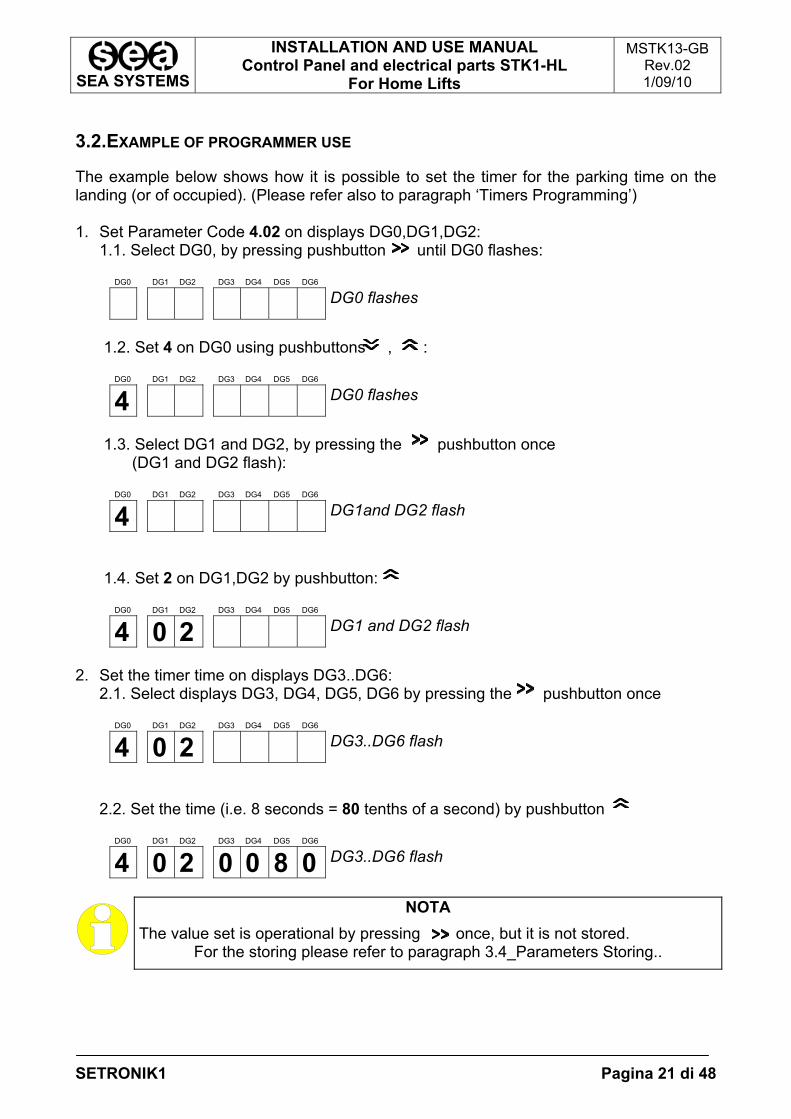
3.2.EXAMPLE OF PROGRAMMER USE
The example below shows how it is possible to set the timer for the parking time on the landing (or of occupied). (Please refer also to paragraph ‘Timers Programming’) 1. Set Parameter Code 4.02 on displays DG0,DG1,DG2:
1.1. Select DG0, by pressing pushbutton until DG0 flashes:
DG0 DG1 DG2 DG3 DG4 DG5 DG6
DG0 flashes
1.2. Set 4 on DG0 using pushbuttons , :
DG0 DG1 DG2 DG3 DG4 DG5 DG6
4 DG0 flashes
1.3. Select DG1 and DG2, by pressing the pushbutton once
(DG1 and DG2 flash):
DG0 DG1 DG2 DG3 DG4 DG5 DG6
4 DG1and DG2 flash
1.4. Set 2 on DG1,DG2 by pushbutton:
DG0 DG1 DG2 DG3 DG4 DG5 DG6
4 0 2 DG1 and DG2 flash
2. Set the timer time on displays DG3..DG6:
2.1. Select displays DG3, DG4, DG5, DG6 by pressing the pushbutton once
DG0 DG1 DG2 DG3 DG4 DG5 DG6
4 0 2 DG3..DG6 flash
2.2. Set the time (i.e. 8 seconds = 80 tenths of a second) by pushbutton
DG0 DG1 DG2 DG3 DG4 DG5 DG6
4 0 2 0 0 8 0 DG3..DG6 flash
NOTA The value set is operational by pressing once, but it is not stored.
For the storing please refer to paragraph 3.4_Parameters Storing..
SEA SYSTEMS
INSTALLATION AND USE MANUAL Control Panel and electrical parts STK1-HL
For Home Lifts
MSTK13-GB Rev.02 1/09/10
SETRONIK1 Pagina 22 di 48
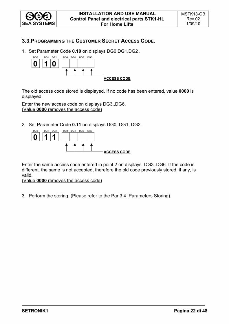
3.3.PROGRAMMING THE CUSTOMER SECRET ACCESS CODE.
1. Set Parameter Code 0.10 on displays DG0,DG1,DG2 . DG0 DG1 DG2 DG3 DG4 DG5 DG6
0 1 0
ACCESS CODE The old access code stored is displayed. If no code has been entered, value 0000 is displayed. Enter the new access code on displays DG3..DG6. (Value 0000 removes the access code) 2. Set Parameter Code 0.11 on displays DG0, DG1, DG2.
DG0 DG1 DG2 DG3 DG4 DG5 DG6
0 1 1
ACCESS CODE Enter the same access code entered in point 2 on displays DG3..DG6. If the code is different, the same is not accepted, therefore the old code previously stored, if any, is valid. (Value 0000 removes the access code) 3. Perform the storing. (Please refer to the Par.3.4_Parameters Storing).
SEA SYSTEMS
INSTALLATION AND USE MANUAL Control Panel and electrical parts STK1-HL
For Home Lifts
MSTK13-GB Rev.02 1/09/10
SETRONIK1 Pagina 23 di 48
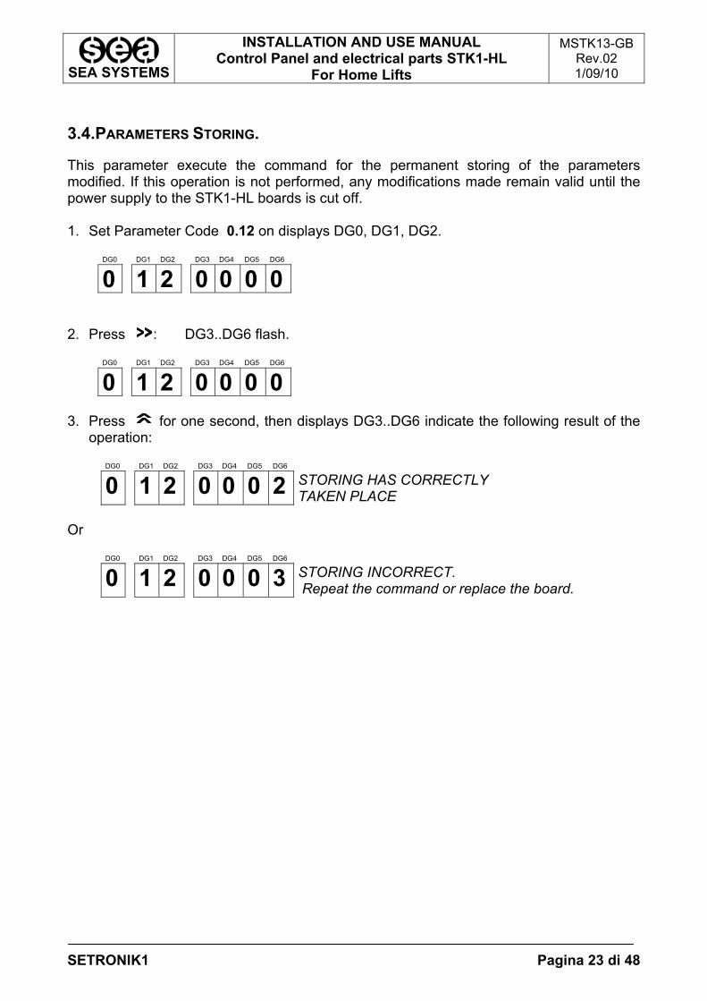
3.4.PARAMETERS STORING.
This parameter execute the command for the permanent storing of the parameters modified. If this operation is not performed, any modifications made remain valid until the power supply to the STK1-HL boards is cut off. 1. Set Parameter Code 0.12 on displays DG0, DG1, DG2.
DG0 DG1 DG2 DG3 DG4 DG5 DG6
0 1 2 0 0 0 0 2. Press : DG3..DG6 flash.
DG0 DG1 DG2 DG3 DG4 DG5 DG6
0 1 2 0 0 0 0 3. Press for one second, then displays DG3..DG6 indicate the following result of the
operation:
DG0 DG1 DG2 DG3 DG4 DG5 DG6
0 1 2 0 0 0 2 STORING HAS CORRECTLY TAKEN PLACE
Or
DG0 DG1 DG2 DG3 DG4 DG5 DG6
0 1 2 0 0 0 3 STORING INCORRECT. Repeat the command or replace the board.
SEA SYSTEMS
INSTALLATION AND USE MANUAL Control Panel and electrical parts STK1-HL
For Home Lifts
MSTK13-GB Rev.02 1/09/10
SETRONIK1 Pagina 24 di 48
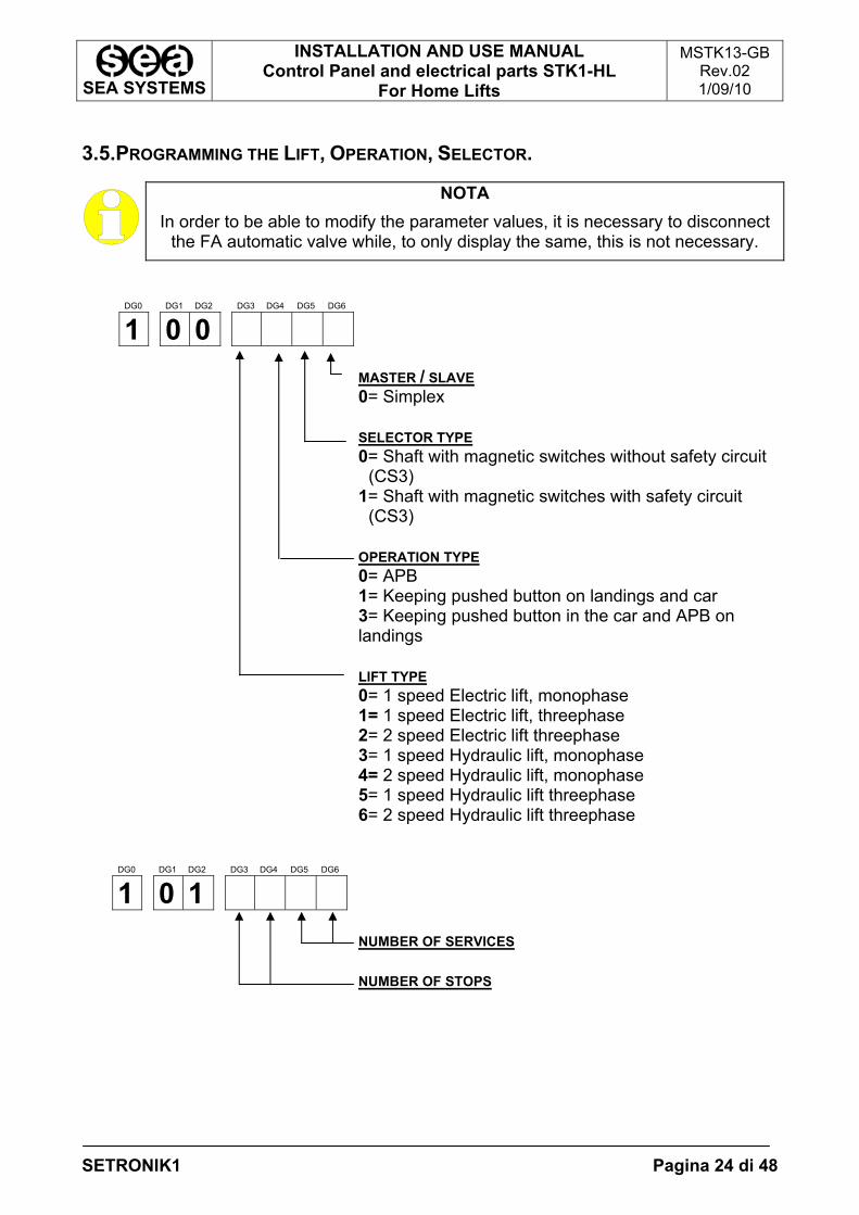
3.5.PROGRAMMING THE LIFT, OPERATION, SELECTOR.
NOTA In order to be able to modify the parameter values, it is necessary to disconnect
the FA automatic valve while, to only display the same, this is not necessary.
DG0 DG1 DG2 DG3 DG4 DG5 DG6
1 0 0
MASTER / SLAVE 0= Simplex SELECTOR TYPE 0= Shaft with magnetic switches without safety circuit
(CS3) 1= Shaft with magnetic switches with safety circuit
(CS3) OPERATION TYPE 0= APB 1= Keeping pushed button on landings and car 3= Keeping pushed button in the car and APB on landings LIFT TYPE 0= 1 speed Electric lift, monophase 1= 1 speed Electric lift, threephase 2= 2 speed Electric lift threephase 3= 1 speed Hydraulic lift, monophase 4= 2 speed Hydraulic lift, monophase 5= 1 speed Hydraulic lift threephase 6= 2 speed Hydraulic lift threephase
DG0 DG1 DG2 DG3 DG4 DG5 DG6
1 0 1
NUMBER OF SERVICES NUMBER OF STOPS
SEA SYSTEMS
INSTALLATION AND USE MANUAL Control Panel and electrical parts STK1-HL
For Home Lifts
MSTK13-GB Rev.02 1/09/10
SETRONIK1 Pagina 25 di 48
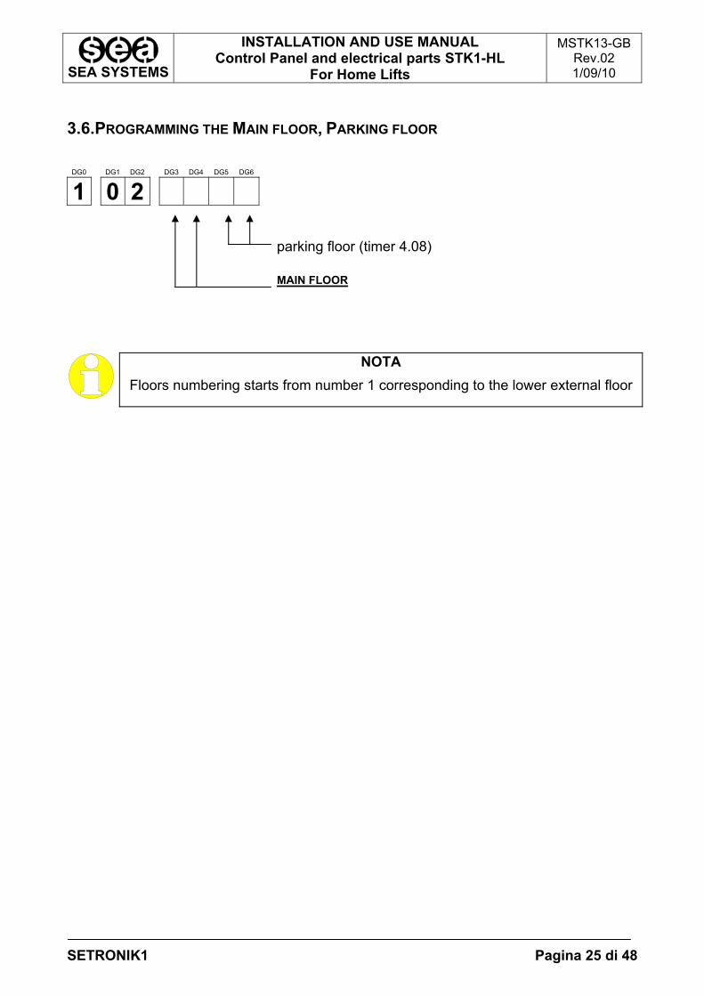
3.6.PROGRAMMING THE MAIN FLOOR, PARKING FLOOR
DG0 DG1 DG2 DG3 DG4 DG5 DG6
1 0 2
parking floor (timer 4.08) MAIN FLOOR
NOTA Floors numbering starts from number 1 corresponding to the lower external floor
SEA SYSTEMS
INSTALLATION AND USE MANUAL Control Panel and electrical parts STK1-HL
For Home Lifts
MSTK13-GB Rev.02 1/09/10
SETRONIK1 Pagina 26 di 48
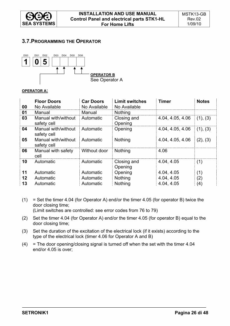
3.7.PROGRAMMING THE OPERATOR
DG0 DG1 DG2 DG3 DG4 DG5 DG6
1 0 5
OPERATOR B See Operator A
OPERATOR A: Floor Doors Car Doors Limit switches Timer Notes 00 No Available No Available No Available 01 Manual Manual Nothing 03 Manual with/without
safety cell Automatic Closing and
Opening 4.04, 4.05, 4.06 (1), (3)
04 Manual with/without safety cell
Automatic Opening 4.04, 4.05, 4.06 (1), (3)
05 Manual with/without safety cell
Automatic Nothing 4.04, 4.05, 4.06 (2), (3)
06 Manual with safety cell
Without door Nothing 4.06
10 Automatic Automatic Closing and Opening
4.04, 4.05 (1)
11 Automatic Automatic Opening 4.04, 4.05 (1) 12 Automatic Automatic Nothing 4.04, 4.05 (2) 13 Automatic Automatic Nothing 4.04, 4.05 (4) (1) = Set the timer 4.04 (for Operator A) end/or the timer 4.05 (for operator B) twice the
door closing time; (Limit switches are controlled: see error codes from 76 to 79)
(2) Set the timer 4.04 (for Operator A) end/or the timer 4.05 (for operator B) equal to the door closing time;
(3) Set the duration of the excitation of the electrical lock (if it exists) according to the type of the electrical lock (timer 4.06 for Operator A and B)
(4) = The door opening/closing signal is turned off when the set with the timer 4.04 end/or 4.05 is over;
SEA SYSTEMS
INSTALLATION AND USE MANUAL Control Panel and electrical parts STK1-HL
For Home Lifts
MSTK13-GB Rev.02 1/09/10
SETRONIK1 Pagina 27 di 48
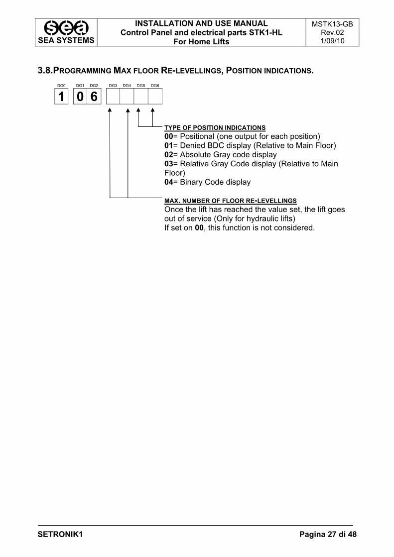
3.8.PROGRAMMING MAX FLOOR RE-LEVELLINGS, POSITION INDICATIONS.
DG0 DG1 DG2 DG3 DG4 DG5 DG6
1 0 6
TYPE OF POSITION INDICATIONS 00= Positional (one output for each position) 01= Denied BDC display (Relative to Main Floor) 02= Absolute Gray code display 03= Relative Gray Code display (Relative to Main Floor) 04= Binary Code display MAX. NUMBER OF FLOOR RE-LEVELLINGS Once the lift has reached the value set, the lift goes out of service (Only for hydraulic lifts) If set on 00, this function is not considered.
SEA SYSTEMS
INSTALLATION AND USE MANUAL Control Panel and electrical parts STK1-HL
For Home Lifts
MSTK13-GB Rev.02 1/09/10
SETRONIK1 Pagina 28 di 48
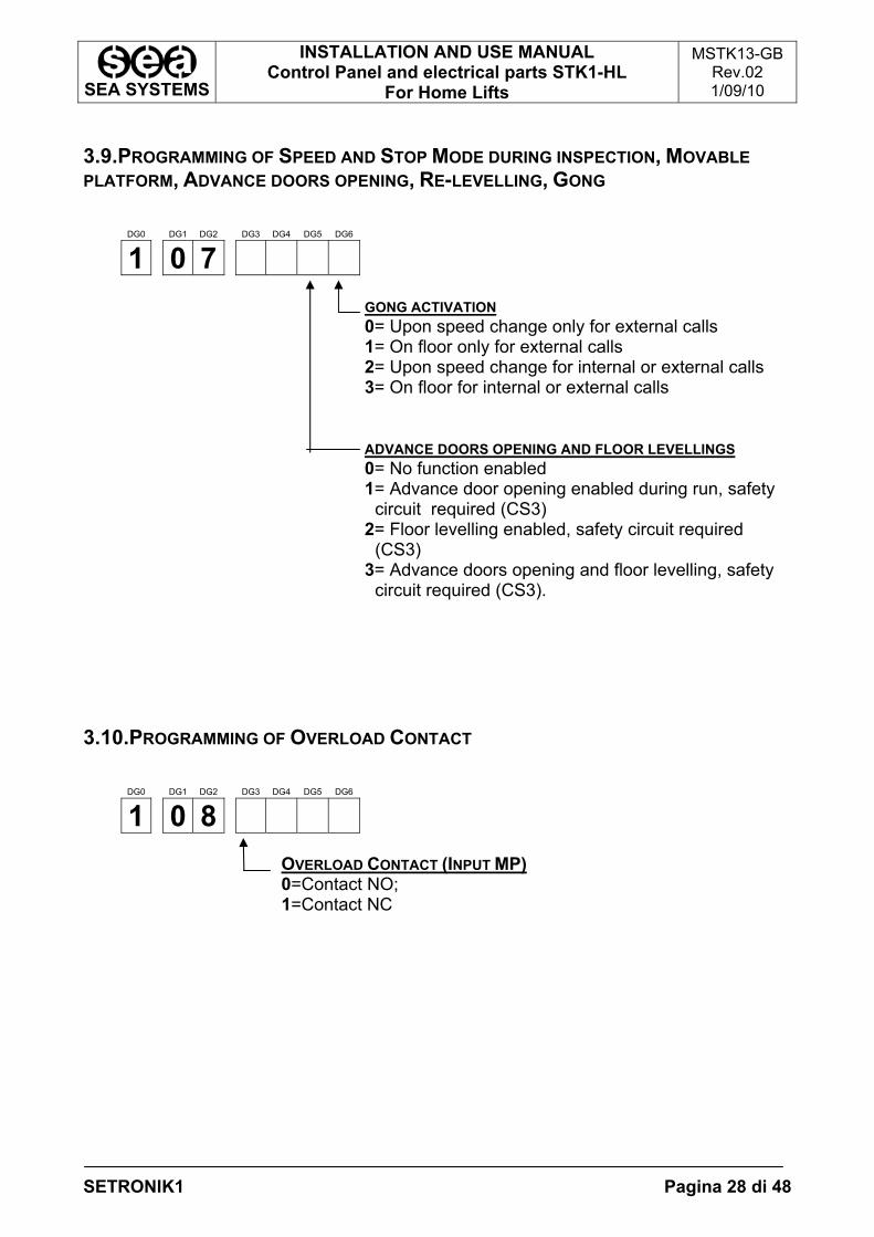
3.9.PROGRAMMING OF SPEED AND STOP MODE DURING INSPECTION, MOVABLE PLATFORM, ADVANCE DOORS OPENING, RE-LEVELLING, GONG
DG0 DG1 DG2 DG3 DG4 DG5 DG6
1 0 7
GONG ACTIVATION 0= Upon speed change only for external calls 1= On floor only for external calls 2= Upon speed change for internal or external calls 3= On floor for internal or external calls ADVANCE DOORS OPENING AND FLOOR LEVELLINGS 0= No function enabled 1= Advance door opening enabled during run, safety
circuit required (CS3) 2= Floor levelling enabled, safety circuit required
(CS3) 3= Advance doors opening and floor levelling, safety
circuit required (CS3).
3.10.PROGRAMMING OF OVERLOAD CONTACT
DG0 DG1 DG2 DG3 DG4 DG5 DG6
1 0 8
OVERLOAD CONTACT (INPUT MP) 0=Contact NO; 1=Contact NC
SEA SYSTEMS
INSTALLATION AND USE MANUAL Control Panel and electrical parts STK1-HL
For Home Lifts
MSTK13-GB Rev.02 1/09/10
SETRONIK1 Pagina 29 di 48
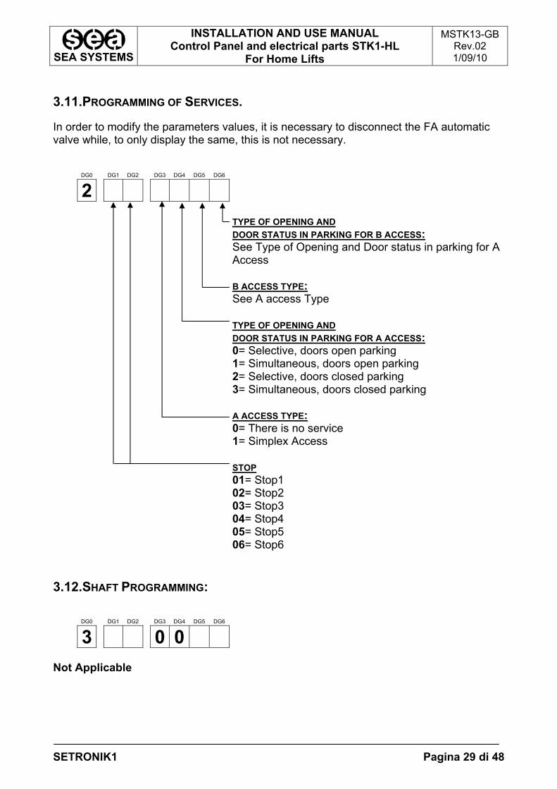
3.11.PROGRAMMING OF SERVICES.
In order to modify the parameters values, it is necessary to disconnect the FA automatic valve while, to only display the same, this is not necessary.
DG0 DG1 DG2 DG3 DG4 DG5 DG6
2
TYPE OF OPENING AND DOOR STATUS IN PARKING FOR B ACCESS: See Type of Opening and Door status in parking for A Access B ACCESS TYPE: See A access Type TYPE OF OPENING AND DOOR STATUS IN PARKING FOR A ACCESS: 0= Selective, doors open parking 1= Simultaneous, doors open parking 2= Selective, doors closed parking 3= Simultaneous, doors closed parking A ACCESS TYPE: 0= There is no service 1= Simplex Access STOP 01= Stop1 02= Stop2 03= Stop3 04= Stop4 05= Stop5 06= Stop6
3.12.SHAFT PROGRAMMING:
DG0 DG1 DG2 DG3 DG4 DG5 DG6
3 0 0 Not Applicable
SEA SYSTEMS
INSTALLATION AND USE MANUAL Control Panel and electrical parts STK1-HL
For Home Lifts
MSTK13-GB Rev.02 1/09/10
SETRONIK1 Pagina 30 di 48
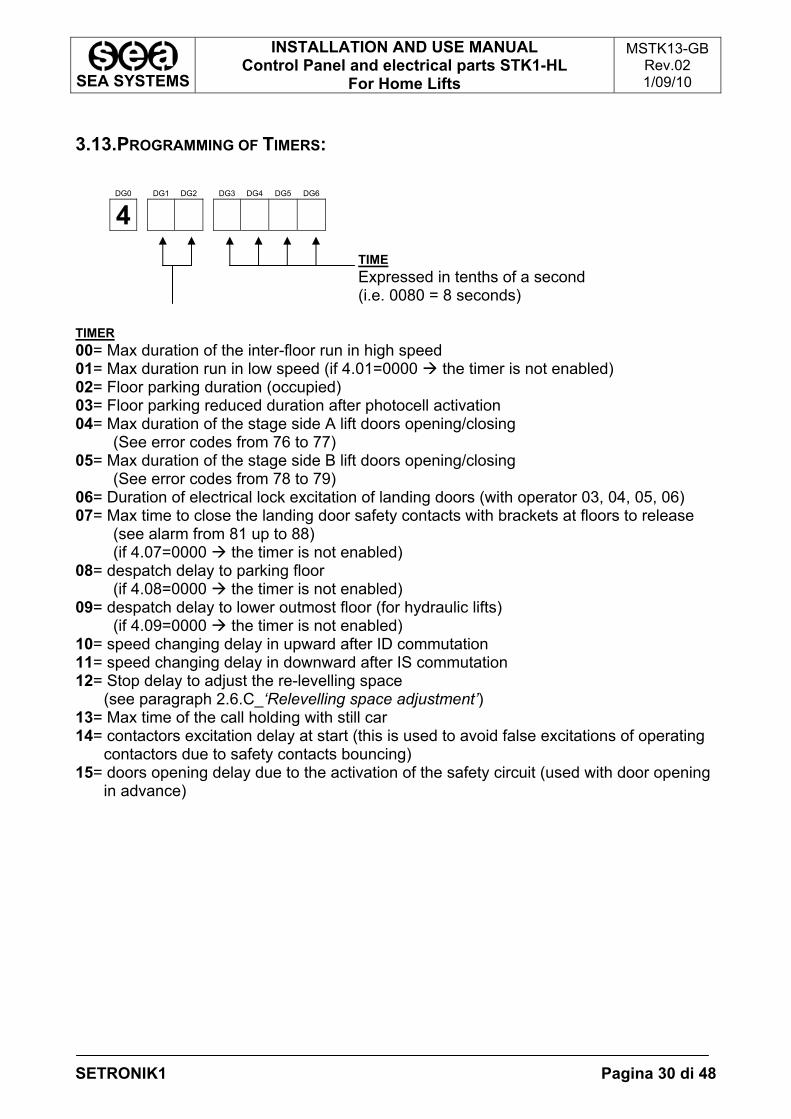
3.13.PROGRAMMING OF TIMERS:
DG0 DG1 DG2 DG3 DG4 DG5 DG6
4
TIME Expressed in tenths of a second (i.e. 0080 = 8 seconds)
TIMER 00= Max duration of the inter-floor run in high speed 01= Max duration run in low speed (if 4.01=0000 the timer is not enabled) 02= Floor parking duration (occupied) 03= Floor parking reduced duration after photocell activation 04= Max duration of the stage side A lift doors opening/closing
(See error codes from 76 to 77) 05= Max duration of the stage side B lift doors opening/closing
(See error codes from 78 to 79) 06= Duration of electrical lock excitation of landing doors (with operator 03, 04, 05, 06) 07= Max time to close the landing door safety contacts with brackets at floors to release
(see alarm from 81 up to 88) (if 4.07=0000 the timer is not enabled)
08= despatch delay to parking floor (if 4.08=0000 the timer is not enabled)
09= despatch delay to lower outmost floor (for hydraulic lifts) (if 4.09=0000 the timer is not enabled)
10= speed changing delay in upward after ID commutation 11= speed changing delay in downward after IS commutation 12= Stop delay to adjust the re-levelling space
(see paragraph 2.6.C_‘Relevelling space adjustment’) 13= Max time of the call holding with still car 14= contactors excitation delay at start (this is used to avoid false excitations of operating
contactors due to safety contacts bouncing) 15= doors opening delay due to the activation of the safety circuit (used with door opening
in advance)
SEA SYSTEMS
INSTALLATION AND USE MANUAL Control Panel and electrical parts STK1-HL
For Home Lifts
MSTK13-GB Rev.02 1/09/10
SETRONIK1 Pagina 31 di 48
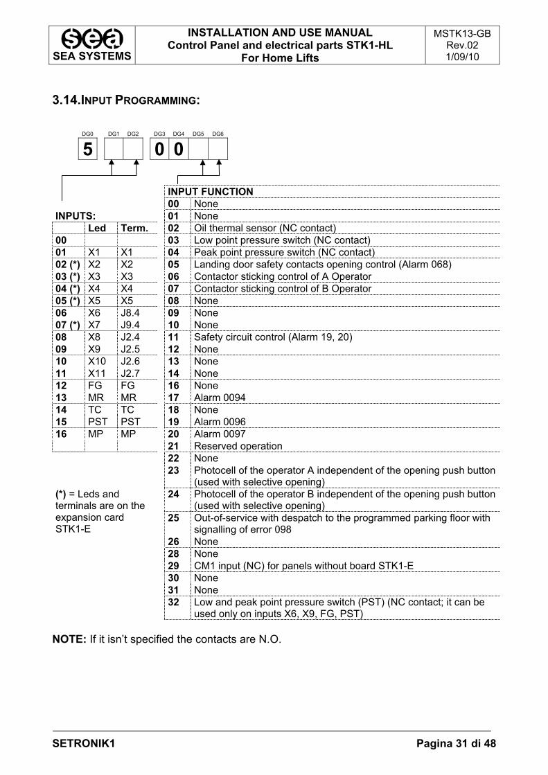
3.14.INPUT PROGRAMMING:
DG0 DG1 DG2 DG3 DG4 DG5 DG6
5 0 0 INPUT FUNCTION 00 None INPUTS: 01 None Led Term. 02 Oil thermal sensor (NC contact) 00 03 Low point pressure switch (NC contact) 01 X1 X1 04 Peak point pressure switch (NC contact) 02 (*) X2 X2 05 Landing door safety contacts opening control (Alarm 068) 03 (*) X3 X3 06 Contactor sticking control of A Operator 04 (*) X4 X4 07 Contactor sticking control of B Operator 05 (*) X5 X5 08 None 06 X6 J8.4 09 None 07 (*) X7 J9.4 10 None 08 X8 J2.4 11 Safety circuit control (Alarm 19, 20) 09 X9 J2.5 12 None 10 X10 J2.6 13 None 11 X11 J2.7 14 None 12 FG FG 16 None 13 MR MR 17 Alarm 0094 14 TC TC 18 None 15 PST PST 19 Alarm 0096 16 MP MP 20 Alarm 0097 21 Reserved operation 22 None 23 Photocell of the operator A independent of the opening push button
(used with selective opening) 24 Photocell of the operator B independent of the opening push button
(used with selective opening) 25 Out-of-service with despatch to the programmed parking floor with
signalling of error 098
(*) = Leds and terminals are on the expansion card STK1-E
26 None 28 None 29 CM1 input (NC) for panels without board STK1-E 30 None 31 None 32 Low and peak point pressure switch (PST) (NC contact; it can be
used only on inputs X6, X9, FG, PST) NOTE: If it isn’t specified the contacts are N.O.
SEA SYSTEMS
INSTALLATION AND USE MANUAL Control Panel and electrical parts STK1-HL
For Home Lifts
MSTK13-GB Rev.02 1/09/10
SETRONIK1 Pagina 32 di 48
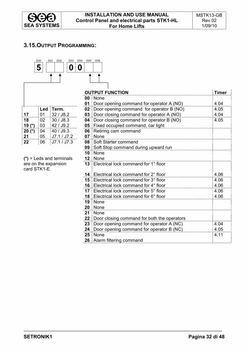
3.15.OUTPUT PROGRAMMING:
DG0 DG1 DG2 DG3 DG4 DG5 DG6
5 0 0 OUTPUT FUNCTION Timer 00 None 01 Door opening command for operator A (NO) 4.04 Led Term. 02 Door opening command for operator B (NO) 4.05 17 01 32 / J8.2 03 Door closing command for operator A (NO) 4.04 18 02 30 / J8.3 04 Door closing command for operator B (NO) 4.05 19 (*) 03 42 / J9.2 05 Fixed occupied command, car light 20 (*) 04 40 / J9.3 06 Retiring cam command 21 05 J7.1 / J7.2 07 None 22 06 J7.1 / J7.3 08 Soft Starter command 09 Soft Stop command during upward run 10 None
12 None (*) = Leds and terminals are on the expansion card STK1-E
13 Electrical lock command for 1° floor
14 Electrical lock command for 2° floor 4.06 15 Electrical lock command for 3° floor 4.06 16 Electrical lock command for 4° floor 4.06 17 Electrical lock command for 5° floor 4.06 18 Electrical lock command for 6° floor 4.06 19 None 20 None 21 None 22 Door closing command for both the operators 23 Door opening command for operator A (NC) 4.04 24 Door opening command for operator B (NC) 4.05 25 None 4.11 26 Alarm filtering command
SEA SYSTEMS
INSTALLATION AND USE MANUAL Control Panel and electrical parts STK1-HL
For Home Lifts
MSTK13-GB Rev.02 1/09/10
SETRONIK1 Pagina 33 di 48
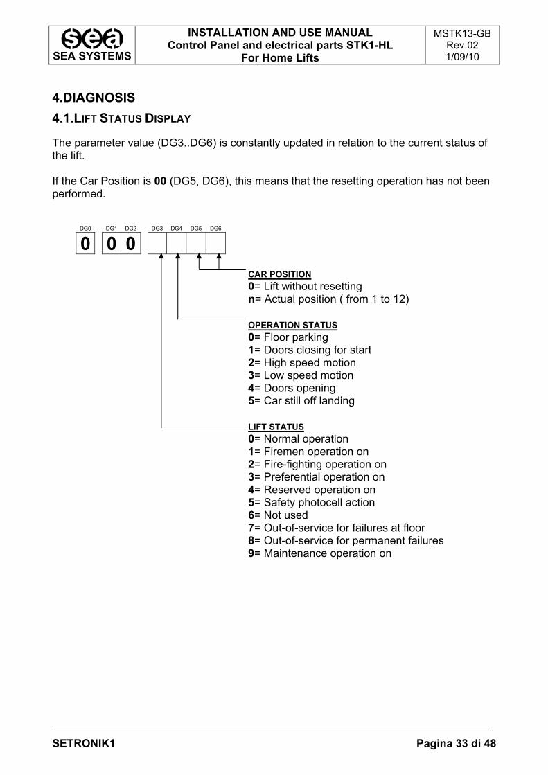
4.DIAGNOSIS 4.1.LIFT STATUS DISPLAY
The parameter value (DG3..DG6) is constantly updated in relation to the current status of the lift. If the Car Position is 00 (DG5, DG6), this means that the resetting operation has not been performed.
DG0 DG1 DG2 DG3 DG4 DG5 DG6
0 0 0
CAR POSITION 0= Lift without resetting n= Actual position ( from 1 to 12) OPERATION STATUS 0= Floor parking 1= Doors closing for start 2= High speed motion 3= Low speed motion 4= Doors opening 5= Car still off landing LIFT STATUS 0= Normal operation 1= Firemen operation on 2= Fire-fighting operation on 3= Preferential operation on 4= Reserved operation on 5= Safety photocell action 6= Not used 7= Out-of-service for failures at floor 8= Out-of-service for permanent failures 9= Maintenance operation on
SEA SYSTEMS
INSTALLATION AND USE MANUAL Control Panel and electrical parts STK1-HL
For Home Lifts
MSTK13-GB Rev.02 1/09/10
SETRONIK1 Pagina 34 di 48
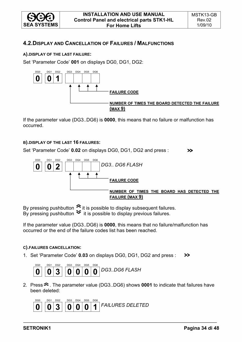
4.2.DISPLAY AND CANCELLATION OF FAILURES / MALFUNCTIONS
A).DISPLAY OF THE LAST FAILURE: Set ‘Parameter Code’ 001 on displays DG0, DG1, DG2:
DG0 DG1 DG2 DG3 DG4 DG5 DG6
0 0 1
FAILURE CODE NUMBER OF TIMES THE BOARD DETECTED THE FAILURE (MAX 9)
If the parameter value (DG3..DG6) is 0000, this means that no failure or malfunction has occurred. B).DISPLAY OF THE LAST 16 FAILURES: Set ‘Parameter Code’ 0.02 on displays DG0, DG1, DG2 and press :
DG0 DG1 DG2 DG3 DG4 DG5 DG6
0 0 2 DG3.. DG6 FLASH
FAILURE CODE NUMBER OF TIMES THE BOARD HAS DETECTED THE FAILURE (MAX 9)
By pressing pushbutton it is possible to display subsequent failures. By pressing pushbutton it is possible to display previous failures. If the parameter value (DG3..DG6) is 0000, this means that no failure/malfunction has occurred or the end of the failure codes list has been reached. C).FAILURES CANCELLATION: 1. Set ‘Parameter Code’ 0.03 on displays DG0, DG1, DG2 and press :
DG0 DG1 DG2 DG3 DG4 DG5 DG6
0 0 3 0 0 0 0 DG3..DG6 FLASH
2. Press . The parameter value (DG3..DG6) shows 0001 to indicate that failures have
been deleted:
DG0 DG1 DG2 DG3 DG4 DG5 DG6
0 0 3 0 0 0 1 FAILURES DELETED
SEA SYSTEMS
INSTALLATION AND USE MANUAL Control Panel and electrical parts STK1-HL
For Home Lifts
MSTK13-GB Rev.02 1/09/10
SETRONIK1 Pagina 35 di 48
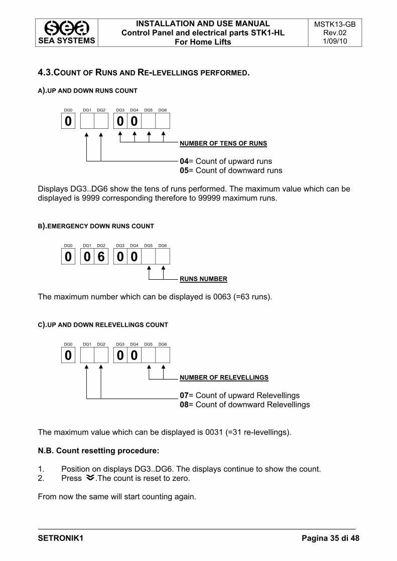
4.3.COUNT OF RUNS AND RE-LEVELLINGS PERFORMED.
A).UP AND DOWN RUNS COUNT
DG0 DG1 DG2 DG3 DG4 DG5 DG6
0 0 0
NUMBER OF TENS OF RUNS 04= Count of upward runs 05= Count of downward runs
Displays DG3..DG6 show the tens of runs performed. The maximum value which can be displayed is 9999 corresponding therefore to 99999 maximum runs. B).EMERGENCY DOWN RUNS COUNT
DG0 DG1 DG2 DG3 DG4 DG5 DG6
0 0 6 0 0
RUNS NUMBER The maximum number which can be displayed is 0063 (=63 runs). C).UP AND DOWN RELEVELLINGS COUNT
DG0 DG1 DG2 DG3 DG4 DG5 DG6
0 0 0
NUMBER OF RELEVELLINGS 07= Count of upward Relevellings 08= Count of downward Relevellings
The maximum value which can be displayed is 0031 (=31 re-levellings). N.B. Count resetting procedure: 1. Position on displays DG3..DG6. The displays continue to show the count. 2. Press .The count is reset to zero. From now the same will start counting again.
SEA SYSTEMS
INSTALLATION AND USE MANUAL Control Panel and electrical parts STK1-HL
For Home Lifts
MSTK13-GB Rev.02 1/09/10
SETRONIK1 Pagina 36 di 48
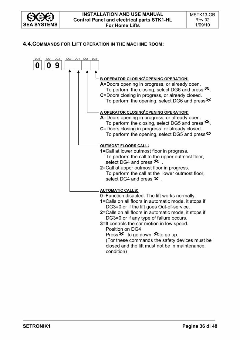
4.4.COMMANDS FOR LIFT OPERATION IN THE MACHINE ROOM:
DG0 DG1 DG2 DG3 DG4 DG5 DG6
0 0 9
B OPERATOR CLOSING\OPENING OPERATION: A=Doors opening in progress, or already open.
To perform the closing, select DG6 and press . C=Doors closing in progress, or already closed.
To perform the opening, select DG6 and press A OPERATOR CLOSING\OPENING OPERATION: A=Doors opening in progress, or already open.
To perform the closing, select DG5 and press . C=Doors closing in progress, or already closed.
To perform the opening, select DG5 and press OUTMOST FLOORS CALL: 1=Call at lower outmost floor in progress.
To perform the call to the upper outmost floor, select DG4 and press .
2=Call at upper outmost floor in progress. To perform the call at the lower outmost floor, select DG4 and press .
AUTOMATIC CALLS: 0=Function disabled. The lift works normally. 1=Calls on all floors in automatic mode, it stops if
DG3=0 or if the lift goes Out-of-service. 2=Calls on all floors in automatic mode, it stops if
DG3=0 or if any type of failure occurs. 3=It controls the car motion in low speed.
Position on DG4 Press to go down, to go up. (For these commands the safety devices must be closed and the lift must not be in maintenance condition)
SEA SYSTEMS
INSTALLATION AND USE MANUAL Control Panel and electrical parts STK1-HL
For Home Lifts
MSTK13-GB Rev.02 1/09/10
SETRONIK1 Pagina 37 di 48
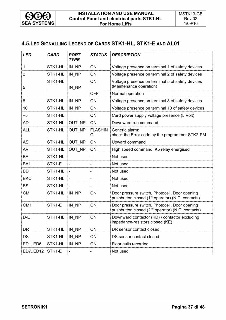
4.5.LED SIGNALLING LEGEND OF CARDS STK1-HL, STK1-E AND AL01
LED CARD PORT TYPE
STATUS DESCRIPTION
1 STK1-HL IN_NP ON Voltage presence on terminal 1 of safety devices
2 STK1-HL IN_NP ON Voltage presence on terminal 2 of safety devices
ON Voltage presence on terminal 5 of safety devices (Maintenance operation) 5
STK1-HL IN_NP
OFF Normal operation
8 STK1-HL IN_NP ON Voltage presence on terminal 8 of safety devices
10 STK1-HL IN_NP ON Voltage presence on terminal 10 of safety devices
+5 STK1-HL ON Card power supply voltage presence (5 Volt)
AD STK1-HL OUT_NP ON Downward run command
ALL STK1-HL OUT_NP FLASHING
Generic alarm: check the Error code by the programmer STK2-PM
AS STK1-HL OUT_NP ON Upward command
AV STK1-HL OUT_NP ON High speed command: K5 relay energised
BA STK1-HL - - Not used
BA1 STK1-E - - Not used
BD STK1-HL - - Not used
BKC STK1-HL - - Not used
BS STK1-HL - - Not used
CM STK1-HL IN_NP ON Door pressure switch, Photocell, Door opening pushbutton closed (1st operator) (N.C. contacts)
CM1 STK1-E IN_NP ON Door pressure switch, Photocell, Door opening pushbutton closed (2nd operator) (N.C. contacts)
D-E STK1-HL IN_NP ON Downward contactor (KD) \ contactor excluding impedance-resistors closed (KE)
DR STK1-HL IN_NP ON DR sensor contact closed
DS STK1-HL IN_NP ON DS sensor contact closed
ED1..ED6 STK1-HL IN_NP ON Floor calls recorded
ED7..ED12 STK1-E - - Not used
SEA SYSTEMS
INSTALLATION AND USE MANUAL Control Panel and electrical parts STK1-HL
For Home Lifts
MSTK13-GB Rev.02 1/09/10
SETRONIK1 Pagina 38 di 48
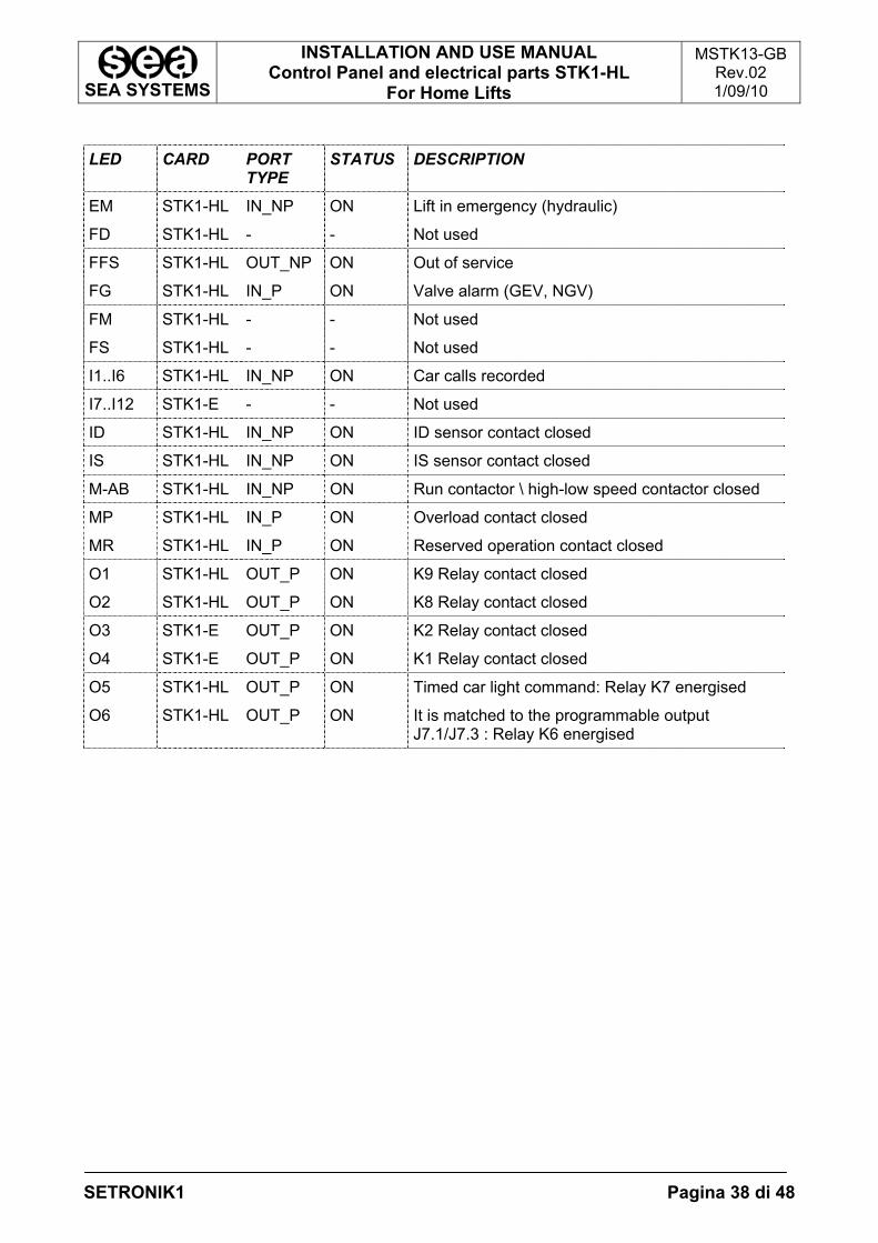
LED CARD PORT
TYPE STATUS DESCRIPTION
EM STK1-HL IN_NP ON Lift in emergency (hydraulic)
FD STK1-HL - - Not used
FFS STK1-HL OUT_NP ON Out of service
FG STK1-HL IN_P ON Valve alarm (GEV, NGV)
FM STK1-HL - - Not used
FS STK1-HL - - Not used
I1..I6 STK1-HL IN_NP ON Car calls recorded
I7..I12 STK1-E - - Not used
ID STK1-HL IN_NP ON ID sensor contact closed
IS STK1-HL IN_NP ON IS sensor contact closed
M-AB STK1-HL IN_NP ON Run contactor \ high-low speed contactor closed
MP STK1-HL IN_P ON Overload contact closed
MR STK1-HL IN_P ON Reserved operation contact closed
O1 STK1-HL OUT_P ON K9 Relay contact closed
O2 STK1-HL OUT_P ON K8 Relay contact closed
O3 STK1-E OUT_P ON K2 Relay contact closed
O4 STK1-E OUT_P ON K1 Relay contact closed
O5 STK1-HL OUT_P ON Timed car light command: Relay K7 energised
O6 STK1-HL OUT_P ON It is matched to the programmable output J7.1/J7.3 : Relay K6 energised
SEA SYSTEMS
INSTALLATION AND USE MANUAL Control Panel and electrical parts STK1-HL
For Home Lifts
MSTK13-GB Rev.02 1/09/10
SETRONIK1 Pagina 39 di 48
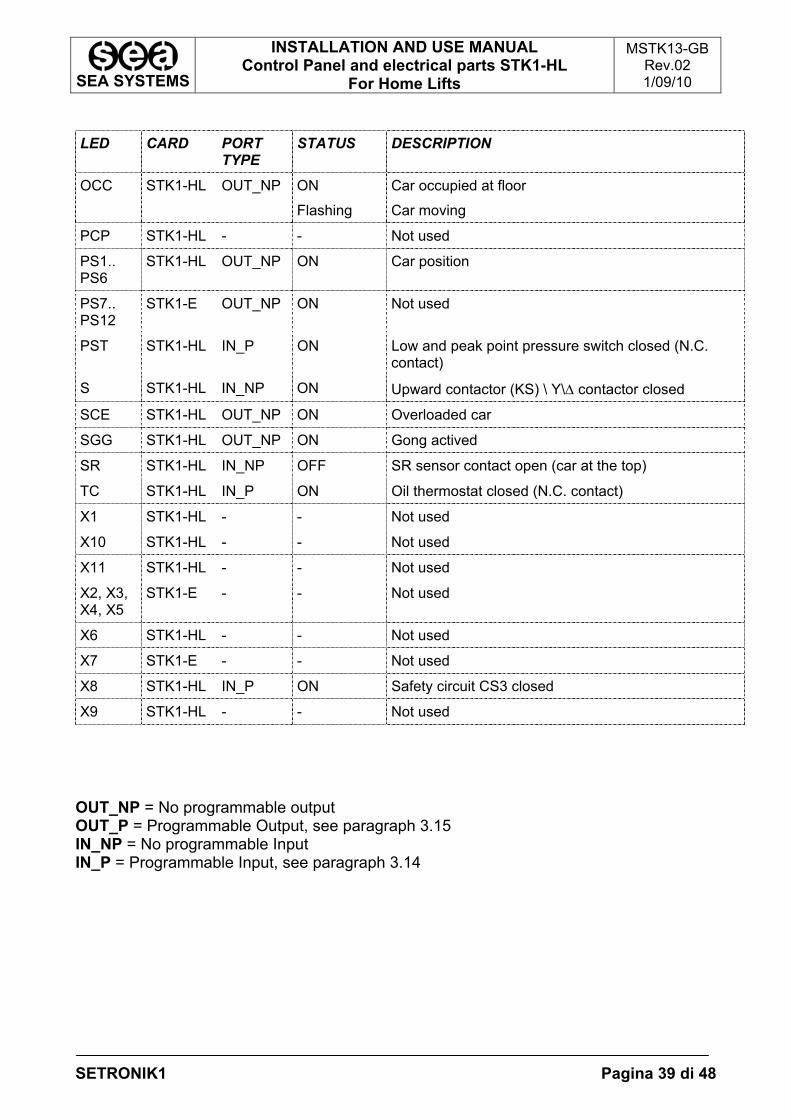
LED CARD PORT
TYPE STATUS DESCRIPTION
OCC STK1-HL OUT_NP ON
Flashing
Car occupied at floor
Car moving
PCP STK1-HL - - Not used
PS1.. PS6
STK1-HL OUT_NP ON Car position
PS7.. PS12
STK1-E OUT_NP ON Not used
PST STK1-HL IN_P ON Low and peak point pressure switch closed (N.C. contact)
S STK1-HL IN_NP ON Upward contactor (KS) \ Y\∆ contactor closed
SCE STK1-HL OUT_NP ON Overloaded car
SGG STK1-HL OUT_NP ON Gong actived
SR STK1-HL IN_NP OFF SR sensor contact open (car at the top)
TC STK1-HL IN_P ON Oil thermostat closed (N.C. contact)
X1 STK1-HL - - Not used
X10 STK1-HL - - Not used
X11 STK1-HL - - Not used
X2, X3, X4, X5
STK1-E - - Not used
X6 STK1-HL - - Not used
X7 STK1-E - - Not used
X8 STK1-HL IN_P ON Safety circuit CS3 closed
X9 STK1-HL - - Not used OUT_NP = No programmable output OUT_P = Programmable Output, see paragraph 3.15 IN_NP = No programmable Input IN_P = Programmable Input, see paragraph 3.14
SEA SYSTEMS
INSTALLATION AND USE MANUAL Control Panel and electrical parts STK1-HL
For Home Lifts
MSTK13-GB Rev.02 1/09/10
SETRONIK1 Pagina 40 di 48
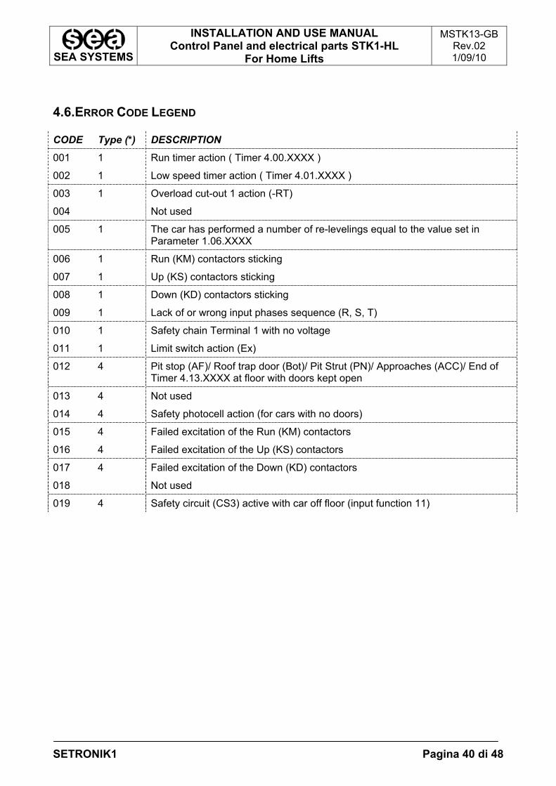
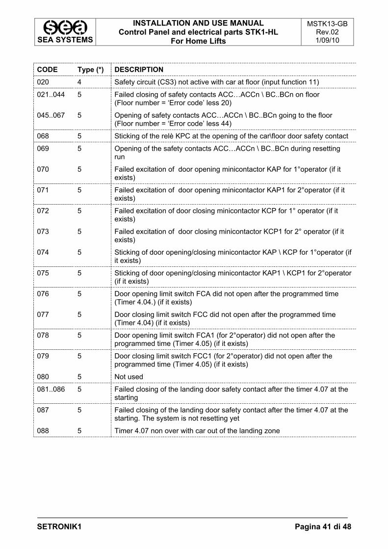
4.6.ERROR CODE LEGEND
CODE Type (*) DESCRIPTION 001 1 Run timer action ( Timer 4.00.XXXX )
002 1 Low speed timer action ( Timer 4.01.XXXX )
003 1 Overload cut-out 1 action (-RT)
004 Not used
005 1 The car has performed a number of re-levelings equal to the value set in Parameter 1.06.XXXX
006 1 Run (KM) contactors sticking
007 1 Up (KS) contactors sticking
008 1 Down (KD) contactors sticking
009 1 Lack of or wrong input phases sequence (R, S, T)
010 1 Safety chain Terminal 1 with no voltage
011 1 Limit switch action (Ex)
012 4 Pit stop (AF)/ Roof trap door (Bot)/ Pit Strut (PN)/ Approaches (ACC)/ End of Timer 4.13.XXXX at floor with doors kept open
013 4 Not used
014 4 Safety photocell action (for cars with no doors)
015 4 Failed excitation of the Run (KM) contactors
016 4 Failed excitation of the Up (KS) contactors
017 4 Failed excitation of the Down (KD) contactors
018 Not used
019 4 Safety circuit (CS3) active with car off floor (input function 11)
SEA SYSTEMS
INSTALLATION AND USE MANUAL Control Panel and electrical parts STK1-HL
For Home Lifts
MSTK13-GB Rev.02 1/09/10
SETRONIK1 Pagina 41 di 48
CODE Type (*) DESCRIPTION
020 4 Safety circuit (CS3) not active with car at floor (input function 11)
021..044 5 Failed closing of safety contacts ACC…ACCn \ BC..BCn on floor (Floor number = ‘Error code’ less 20)
045..067 5 Opening of safety contacts ACC…ACCn \ BC..BCn going to the floor (Floor number = ‘Error code’ less 44)
068 5 Sticking of the relè KPC at the opening of the car\floor door safety contact
069 5 Opening of the safety contacts ACC…ACCn \ BC..BCn during resetting run
070 5 Failed excitation of door opening minicontactor KAP for 1°operator (if it exists)
071 5 Failed excitation of door opening minicontactor KAP1 for 2°operator (if it exists)
072 5 Failed excitation of door closing minicontactor KCP for 1° operator (if it exists)
073 5 Failed excitation of door closing minicontactor KCP1 for 2° operator (if it exists)
074 5 Sticking of door opening/closing minicontactor KAP \ KCP for 1°operator (if it exists)
075 5 Sticking of door opening/closing minicontactor KAP1 \ KCP1 for 2°operator (if it exists)
076 5 Door opening limit switch FCA did not open after the programmed time (Timer 4.04.) (if it exists)
077 5 Door closing limit switch FCC did not open after the programmed time (Timer 4.04) (if it exists)
078 5 Door opening limit switch FCA1 (for 2°operator) did not open after the programmed time (Timer 4.05) (if it exists)
079 5 Door closing limit switch FCC1 (for 2°operator) did not open after the programmed time (Timer 4.05) (if it exists)
080 5 Not used
081..086 5 Failed closing of the landing door safety contact after the timer 4.07 at the starting
087 5 Failed closing of the landing door safety contact after the timer 4.07 at the starting. The system is not resetting yet
088 5 Timer 4.07 non over with car out of the landing zone
SEA SYSTEMS
INSTALLATION AND USE MANUAL Control Panel and electrical parts STK1-HL
For Home Lifts
MSTK13-GB Rev.02 1/09/10
SETRONIK1 Pagina 42 di 48
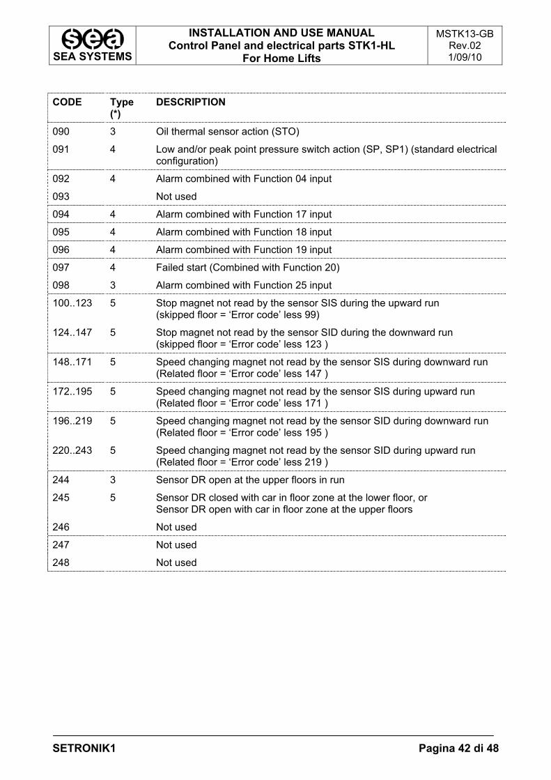
CODE Type
(*) DESCRIPTION
090 3 Oil thermal sensor action (STO)
091 4 Low and/or peak point pressure switch action (SP, SP1) (standard electrical configuration)
092 4 Alarm combined with Function 04 input
093 Not used
094 4 Alarm combined with Function 17 input
095 4 Alarm combined with Function 18 input
096 4 Alarm combined with Function 19 input
097 4 Failed start (Combined with Function 20)
098 3 Alarm combined with Function 25 input
100..123 5 Stop magnet not read by the sensor SIS during the upward run (skipped floor = ‘Error code’ less 99)
124..147 5 Stop magnet not read by the sensor SID during the downward run (skipped floor = ‘Error code’ less 123 )
148..171 5 Speed changing magnet not read by the sensor SIS during downward run (Related floor = ‘Error code’ less 147 )
172..195 5 Speed changing magnet not read by the sensor SIS during upward run (Related floor = ‘Error code’ less 171 )
196..219 5 Speed changing magnet not read by the sensor SID during downward run (Related floor = ‘Error code’ less 195 )
220..243 5 Speed changing magnet not read by the sensor SID during upward run (Related floor = ‘Error code’ less 219 )
244 3 Sensor DR open at the upper floors in run
245 5 Sensor DR closed with car in floor zone at the lower floor, or Sensor DR open with car in floor zone at the upper floors
246 Not used
247 Not used
248 Not used
SEA SYSTEMS
INSTALLATION AND USE MANUAL Control Panel and electrical parts STK1-HL
For Home Lifts
MSTK13-GB Rev.02 1/09/10
SETRONIK1 Pagina 43 di 48
(*) Alarm type legend 1 = Permanent alarm that put the system out of order. It’s request a manual reset 2 = Permanent alarm that put the system out of order with car at floor. It’s request a manual reset. 3 = Temporary alarm that put the system out of order with car at floor or anyway still. 4 = Temporary alarm that put the system immediately out of order. 5 = alarm that don’t put the system out of order, but the are stored.
HIGHLIGHT The diagnosing of the system is done not only with the STK2-PM device but also
with the leds on the STK1-HL board
SEA SYSTEMS
INSTALLATION AND USE MANUAL Control Panel and electrical parts STK1-HL
For Home Lifts
MSTK13-GB Rev.02 1/09/10
SETRONIK1 Pagina 44 di 48
5.MAINTENANCE Before carrying out any cleaning or maintenance operations, unplug the appliance from the power supply unit by turning OFF the master switch. While maintenance procedures are in progress, refer to the safety regulations set out in paragraph 2. In no event shall SEA SYSTEMS Srl be liable for any damages whatsoever arising out of the inability to comply with the above instructions and of any improvements as regards configuration, fastening and connections in the originally supplied apparatus. 5.1.BATTERY REPLACEMENT
The control panel is fitted with 2 batteries:
• 12v 1,1Ah The battery lasts approximately 3 years provided it remains charged. Check out its condition on a yearly basis and replace it with one featuring the same characteristics if needed.
5.2.SHAFT SENSORS
Shaft indicators are formed by monostable and/or bistable sensors and their corresponding magnets to enable switching. In order to ensure that sensors switch over properly when placed opposite their corresponding magnets, check out on a yearly basis that: - The distance between the sensor and its corresponding magnet is kept 1 cm apart,
including during machining stress; - Sensors travel the same axis as the magnets; - Magnets have no metal bodies attached; - The brackets for both the sensors and magnets are steadily fastened to the car roof
and the guides.
SEA SYSTEMS
INSTALLATION AND USE MANUAL Control Panel and electrical parts STK1-HL
For Home Lifts
MSTK13-GB Rev.02 1/09/10
SETRONIK1 Pagina 45 di 48
5.3.STK1-HL ELECTRONIC BOARD REPLACEMENT
WARNING The STK1-HL card accommodates circuits connected to the chain of safety devices in compliance with harmonised standards EN81. Should the card be removed for replacement, abide by the instructions reported below, so as not to jeopardise its safe operation.
1. Before carrying out any operations, make sure that the control panel is de-energised; 2. Visually check that the supporting structure and the card are in suitable conditions,
i.e., that they show no dents that could result in short-circuits; 3. To secure the card and prevent it from being damaged, use M3X8 type of screws only
and a suitable cross tip screwdriver; 4. Engage all the retaining screws for the card to be tightly anchored to the frame; 5. Insert all the connectors retrieved from the control panel wiring board; 6. When peeling the wires for connection purposes, turn them towards the outside of the
cabinet to avoid ejecting copper wires towards the card; 7. Visually check the card and make sure that there are no foreign bodies, such as
flakes of dry plaster, pieces of electric wire or conduction material; 8. While tightening the removable jumpers screws on the lower side of the card, use an
appropriate screwdriver to avoid card damage in the process.
WARNING The STK1-HL is built exclusively for Home-Lifts. Don’t replace it with STK1-b card
SEA SYSTEMS
INSTALLATION AND USE MANUAL Control Panel and electrical parts STK1-HL
For Home Lifts
MSTK13-GB Rev.02 1/09/10
SETRONIK1 Pagina 46 di 48
5.4.CS3 SAFETY CIRCUIT REPLACEMENT
WARNING The Safety Circuit CS1 has not electronic components with contact function, so it is not a safety component according to the 95/16 directive. Should the card be removed for replacement, abide by the instructions reported below, so as not to jeopardise its safe operation.
1. Before carrying out any operations, make sure that the control panel is de-energised. 2. The CS3 safety circuit is anchored to a DIN guide, driven into the control panel; to
remove the device from the DIN guide, use an appropriate screwdriver to loosen the upper tab of the device.
WARNING Do not open the casing covering the CS3 device.
3. Use an appropriate screwdriver to disconnect/reconnect the CS3 device to/from the
control panel.
HIGHLIGHT In order to avoid making erroneous connections to the CS3 device, we
recommend that you identify each connector with the name of the corresponding jumper on the CS3 device before carrying out any connections.
4. Visually inspect the circuit and look out for possible short-circuits between the jumpers.
SEA SYSTEMS
INSTALLATION AND USE MANUAL Control Panel and electrical parts STK1-HL
For Home Lifts
MSTK13-GB Rev.02 1/09/10
SETRONIK1 Pagina 47 di 48
6.BASIC TROUBLESHOOTING PROCEDURES 6.1.ALARMED CARD (ALL LED ON)
If the card is alarmed (ALL leds ON), locate the error code through the PM programmer (see paragraph 4.6_Alarm Code Legend);
HIGHLIGHT If alarm 9 is displayed (reversed input phases), switch OFF the control panel (QM set to OFF), reverse 2 input phases and switch the panel ON again. If the motor jogs in the opposite direction, reverse 2 panel output phases.
6.2.ERRONEUS READOUT OF THE SHAFT SENSORS
Refer to Paragraph 5.2.
SEA SYSTEMS
INSTALLATION AND USE MANUAL Control Panel and electrical parts STK1-HL
For Home Lifts
MSTK13-GB Rev.02 1/09/10
SETRONIK1 Pagina 48 di 48
7.TECHNICAL DATA Input voltages 110 to 440 Vac (Single-phase and Three-phase)
Operating voltage 48 Vdc
Cam, electro-valves, operators voltages
ON DEMAND
Position, arrows, out-of-service signalling outputs
24 Vdc – 4.5W Max. Each (note *)
Coming, booking, Gong, Overload signalling outputs
24 Vdc – 2.4W Max. Each
Occupied signalling outputs 24 Vdc – 36W Max.
Safety devices inputs OPTO-ISOLATED (Conforming with EN 81 ED.98)
Operating temperature 0 ÷ 40 °C
Logic type MICROPROCESSOR CONTROLLED
Data storage PERMANENT
Re-chargeable battery 12vdc, 2 ÷ 7.5 ah (3 years life if constantly under charge)
HIGHLIGHT If it’s required a power upper than 4,5W, it’s necessary use STK1-RO card