Embed Size (px)
Citation preview
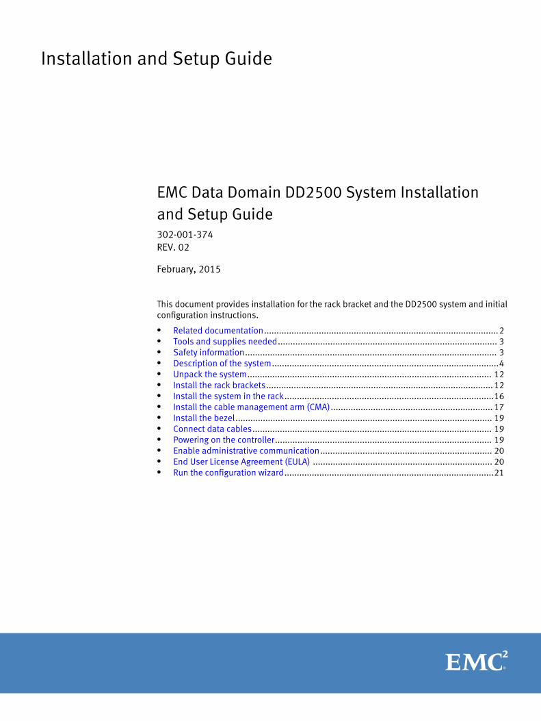
Installation and Setup Guide
EMC Data Domain DD2500 System Installationand Setup Guide302-001-374REV. 02
February, 2015
This document provides installation for the rack bracket and the DD2500 system and initialconfiguration instructions.
l Related documentation..............................................................................................2l Tools and supplies needed........................................................................................ 3l Safety information..................................................................................................... 3l Description of the system...........................................................................................4l Unpack the system.................................................................................................. 12l Install the rack brackets...........................................................................................12l Install the system in the rack....................................................................................16l Install the cable management arm (CMA)................................................................. 17l Install the bezel....................................................................................................... 19l Connect data cables................................................................................................ 19l Powering on the controller....................................................................................... 19l Enable administrative communication..................................................................... 20l End User License Agreement (EULA) ........................................................................ 20l Run the configuration wizard....................................................................................21
Related documentationEMC provides a variety of document types to support our products. End-user documentsinclude user guides, hardware installation guides, administrator guides, software guides,part replacement guides, release notes, and others. Integration documents describe howto integrate Data Domain systems with third party backup applications, and compatibilitymatrices show which components are compatible with each other.
This document refers to other EMC documents by title. To locate a referenced document,go to the EMC Support website at https://support.emc.com, enter the document title inthe search box, and click the search button.
Note
Hard copies of a document may be out of date. Always check for the current version of adocument before you start an upgrade or begin a significant configuration change.
Viewing Data Domain documentsProcedure
1. Log into the EMC Online support site at: https://support.emc.com.
2. To view user documents, click Product Documentation and then perform the followingsteps:
a. Select the Data Domain model from the Platform list and click View.
b. On the row for the correct Data Domain operating system (DD OS) version, clickView under Documentation.
c. Click the desired title.
3. To view integration-related documents, perform the following steps:
a. Click Integration Documentation.
b. Select the vendor from the Vendor dropdown list.
c. Select the desired title from the list.
4. To view compatibility matrices, perform the following steps:
a. Click Compatibility Matrices.
b. Select the desired title from the Current Releases list.
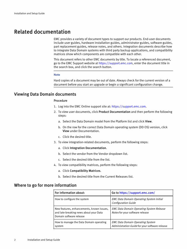
Where to go for more information
For information about: Go to https://support.emc.com/
How to configure the system EMC Data Domain Operating System InitialConfiguration Guide
New features, enhancements, known issues,and late-breaking news about your DataDomain software release
EMC Data Domain Operating System ReleaseNotes for your software release
How to manage the Data Domain operatingsystem
EMC Data Domain Operating SystemAdministration Guide for your software release
Installation and Setup Guide
2 Installation and Setup Guide
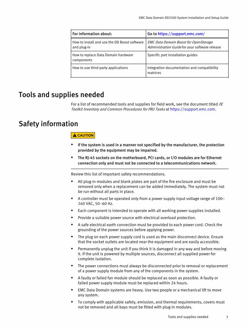
For information about: Go to https://support.emc.com/
How to install and use the DD Boost softwareand plug-in
EMC Data Domain Boost for OpenStorageAdministration Guide for your software release
How to replace Data Domain hardwarecomponents
Specific part installation guides
How to use third-party applications Integration documentation and compatibilitymatrices
Tools and supplies neededFor a list of recommended tools and supplies for field work, see the document titled FEToolkit Inventory and Common Procedures for FRU Tasks at https://support.emc.com.
Safety informationCAUTION
l If the system is used in a manner not specified by the manufacturer, the protectionprovided by the equipment may be impaired.
l The RJ-45 sockets on the motherboard, PCI cards, or I/O modules are for Ethernetconnection only and must not be connected to a telecommunications network.
Review this list of important safety recommendations.
l All plug-in modules and blank plates are part of the fire enclosure and must beremoved only when a replacement can be added immediately. The system must notbe run without all parts in place.
l A controller must be operated only from a power supply input voltage range of 100–240 VAC, 50–60 Hz.
l Each component is intended to operate with all working power supplies installed.
l Provide a suitable power source with electrical overload protection.
l A safe electrical earth connection must be provided to each power cord. Check thegrounding of the power sources before applying power.
l The plug on each power supply cord is used as the main disconnect device. Ensurethat the socket outlets are located near the equipment and are easily accessible.
l Permanently unplug the unit if you think it is damaged in any way and before movingit. If the unit is powered by multiple sources, disconnect all supplied power forcomplete isolation.
l The power connections must always be disconnected prior to removal or replacementof a power supply module from any of the components in the system.
l A faulty or failed fan module should be replaced as soon as possible. A faulty orfailed power supply module must be replaced within 24 hours.
l EMC Data Domain systems are heavy. Use two people or a mechanical lift to moveany system.
l To comply with applicable safety, emission, and thermal requirements, covers mustnot be removed and all bays must be fitted with plug-in modules.
EMC Data Domain DD2500 System Installation and Setup Guide
Tools and supplies needed 3
l Load the rack beginning at the bottom to prevent the rack from becoming top-heavy.
l For ESD protection, EMC Data Domain recommends that you wear a suitable antistaticwrist or ankle strap. Observe all conventional ESD precautions when handling plug-inmodules and components.
l Do not extend components on slide rails until you have loaded at least three or moresimilarly weighted items in the rack, or unless the rack is bolted to the floor oroverhead structure to prevent tipping.
Description of the systemThis section includes site requirements, product specifications, and descriptions of frontand rear panels.
Site requirementsThe site requirements are:
l The system requires 2U of vertical space in a standard 19”, four-post rack. Do not usea two-post rack.
l Use air conditioning that can cope with the maximum BTU/hour thermal rating.
l Temperature control required with a gradient (change) not to exceed 30° C in an hour.
l In a closed or multi-unit rack, ensure that the unit has adequate airflow through thefront bezel and back panel and that ambient temperature requirements are met.
l Ensure that the front bezel and back panel clearances are met.
l Ensure that cables at rear of unit do not obstruct exhaust airflow.
l If installing in a closed cabinet, ensure that the front and rear doors have at least65% open area to ensure adequate airflow for cooling.
l Front bezel requires 1.56 inches (4.0 cm) of unobstructed clearance.
l Back panel requires 5 inches (12.7 cm) of unobstructed clearance.
l AC power outlets must be provided with an earth ground conductor (safety ground). Asafe electrical earth connection must be provided to each power cord.
l Required voltage: 100-120 V~ or 200-240 V~. Frequency: 50 to 60 Hz.
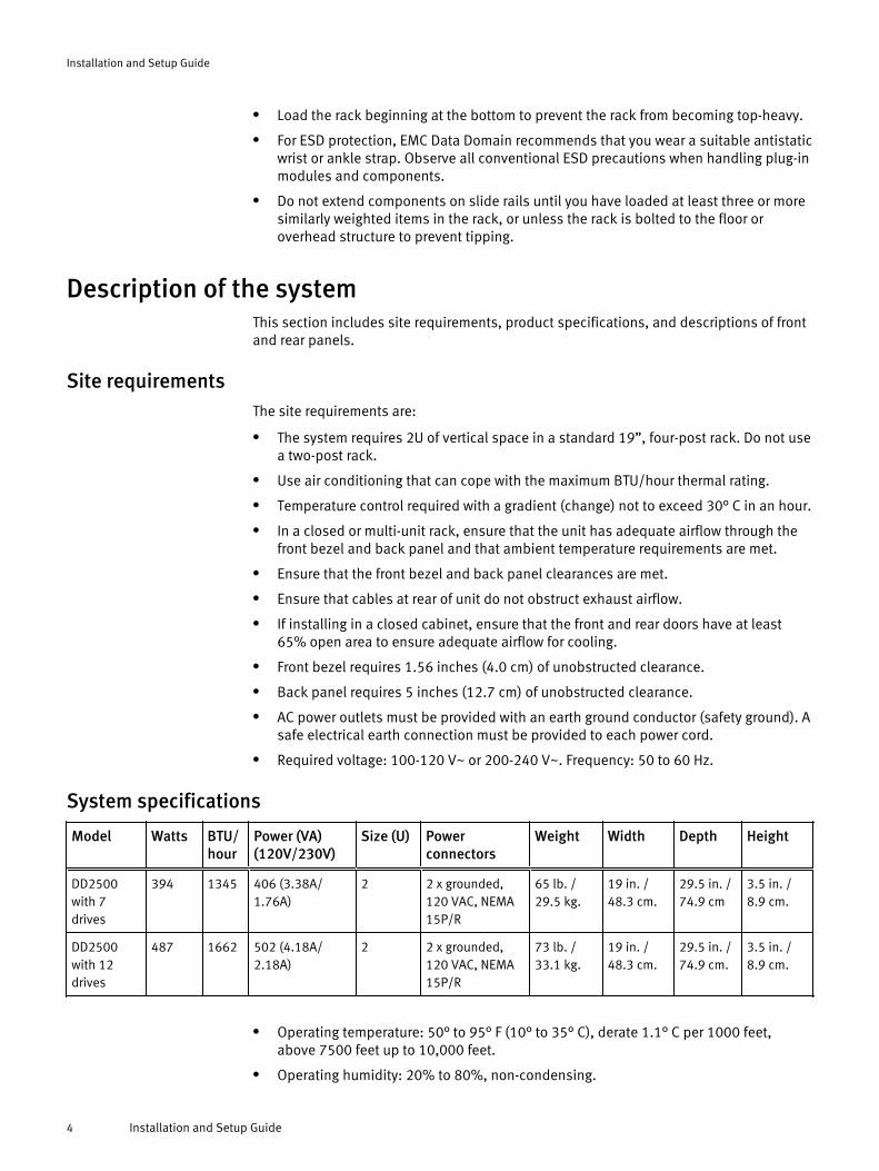
System specifications
Model Watts BTU/hour
Power (VA)(120V/230V)
Size (U) Powerconnectors
Weight Width Depth Height
DD2500with 7drives
394 1345 406 (3.38A/1.76A)
2 2 x grounded,120 VAC, NEMA15P/R
65 lb. /29.5 kg.
19 in. /48.3 cm.
29.5 in. /74.9 cm
3.5 in. /8.9 cm.
DD2500with 12drives
487 1662 502 (4.18A/2.18A)
2 2 x grounded,120 VAC, NEMA15P/R
73 lb. /33.1 kg.
19 in. /48.3 cm.
29.5 in. /74.9 cm.
3.5 in. /8.9 cm.
l Operating temperature: 50° to 95° F (10° to 35° C), derate 1.1° C per 1000 feet,above 7500 feet up to 10,000 feet.
l Operating humidity: 20% to 80%, non-condensing.
Installation and Setup Guide
4 Installation and Setup Guide
l Non-operating temperature: -40° to +149° F (-40° to +65° C).
l Operating acoustic noise: Sound power, LWAd, is 7.52 bels. Sound pressure, LpAm,is 56.4 dB. (Declared noise emission per ISO 9296.)
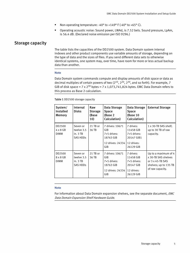
Storage capacityThe table lists the capacities of the DD2500 system. Data Domain system internalindexes and other product components use variable amounts of storage, depending onthe type of data and the sizes of files. If you send different data sets to otherwiseidentical systems, one system may, over time, have room for more or less actual backupdata than another.
Note
Data Domain system commands compute and display amounts of disk space or data asdecimal multiples of certain powers of two (210, 220, 230, and so forth). For example, 7GiB of disk space = 7 x 230 bytes = 7 x 1,073,741,824 bytes. EMC Data Domain refers tothis process as Base 2 calculation.
Table 1 DD2500 storage capacity
System/InstalledMemory
InternalDisks
RawStorage(Base10)
Data StorageSpace(Base 2Calculation)
Data StorageSpace(Base 10Calculation)
External Storage
DD25004 x 8 GBDIMM
Seven ortwelve 3.5in. 3 TBSAS HDDs
21 TB or36 TB
7 drives: 10671GiB7+5 drives:18763 GiB
12 drives: 24334GiB
7 drives:11458 GiB7+5 drives:20147 GiB1
12 drives:26129 GiB
1 x 30-TB SAS shelf;up to 30 TB of rawcapacity.
DD25008 x 8 GBDIMM
Seven ortwelve 3.5in. 3 TBSAS HDDs
21 TB or36 TB
7 drives: 10671GiB7+5 drives:18763 GiB
12 drives: 24334GiB
7 drives:11458 GiB7+5 drives:20147 GiB
12 drives:26129 GiB
Up to a maximum of 4x 30-TB SAS shelvesor 3 x 45-TB SASshelves; up to 135 TBof raw capacity.
Note
For information about Data Domain expansion shelves, see the separate document, EMCData Domain Expansion Shelf Hardware Guide.
EMC Data Domain DD2500 System Installation and Setup Guide
Storage capacity 5
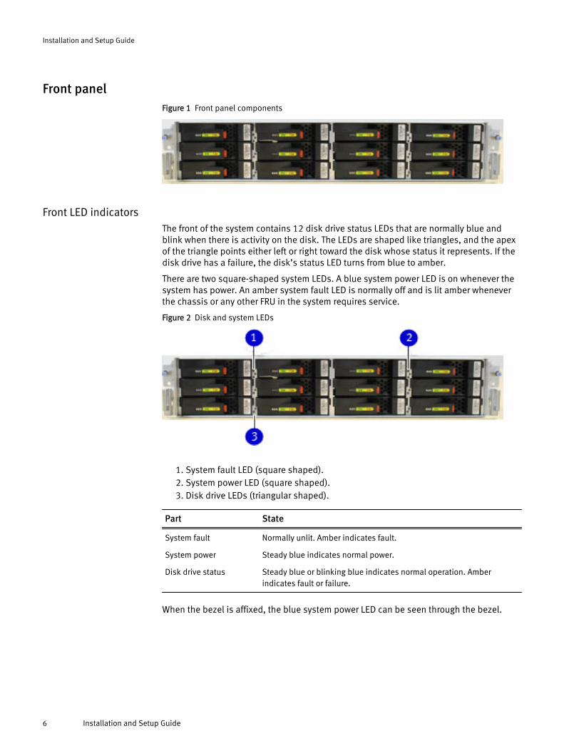
Front panelFigure 1 Front panel components
Front LED indicatorsThe front of the system contains 12 disk drive status LEDs that are normally blue andblink when there is activity on the disk. The LEDs are shaped like triangles, and the apexof the triangle points either left or right toward the disk whose status it represents. If thedisk drive has a failure, the disk’s status LED turns from blue to amber.
There are two square-shaped system LEDs. A blue system power LED is on whenever thesystem has power. An amber system fault LED is normally off and is lit amber wheneverthe chassis or any other FRU in the system requires service.
Figure 2 Disk and system LEDs
1. System fault LED (square shaped).2. System power LED (square shaped).3. Disk drive LEDs (triangular shaped).
Part State
System fault Normally unlit. Amber indicates fault.
System power Steady blue indicates normal power.
Disk drive status Steady blue or blinking blue indicates normal operation. Amberindicates fault or failure.
When the bezel is affixed, the blue system power LED can be seen through the bezel.
Installation and Setup Guide
6 Installation and Setup Guide
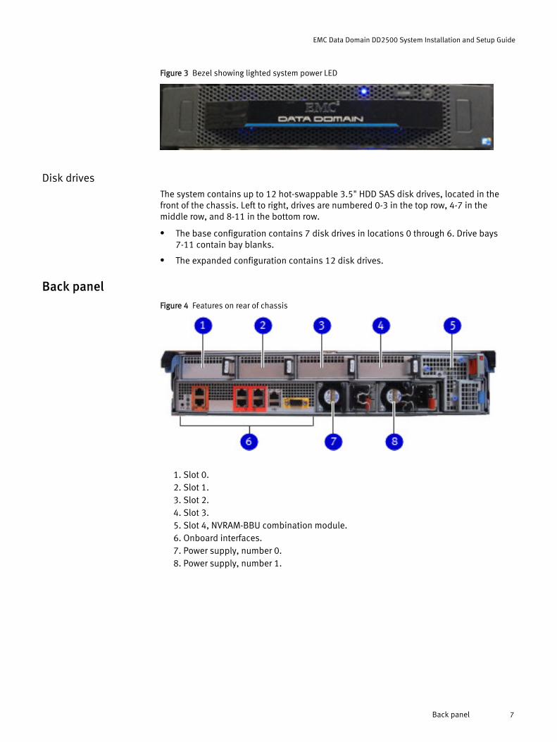
Figure 3 Bezel showing lighted system power LED
Disk drivesThe system contains up to 12 hot-swappable 3.5" HDD SAS disk drives, located in thefront of the chassis. Left to right, drives are numbered 0-3 in the top row, 4-7 in themiddle row, and 8-11 in the bottom row.
l The base configuration contains 7 disk drives in locations 0 through 6. Drive bays7-11 contain bay blanks.
l The expanded configuration contains 12 disk drives.
Back panelFigure 4 Features on rear of chassis
1. Slot 0.2. Slot 1.3. Slot 2.4. Slot 3.5. Slot 4, NVRAM-BBU combination module.6. Onboard interfaces.7. Power supply, number 0.8. Power supply, number 1.
EMC Data Domain DD2500 System Installation and Setup Guide
Back panel 7
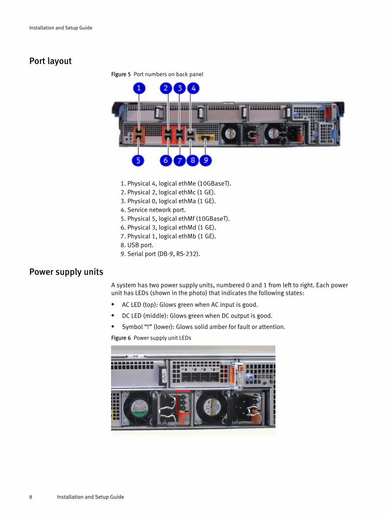
Port layoutFigure 5 Port numbers on back panel
1. Physical 4, logical ethMe (10GBaseT).2. Physical 2, logical ethMc (1 GE).3. Physical 0, logical ethMa (1 GE).4. Service network port.5. Physical 5, logical ethMf (10GBaseT).6. Physical 3, logical ethMd (1 GE).7. Physical 1, logical ethMb (1 GE).8. USB port.9. Serial port (DB-9, RS-232).
Power supply unitsA system has two power supply units, numbered 0 and 1 from left to right. Each powerunit has LEDs (shown in the photo) that indicates the following states:
l AC LED (top): Glows green when AC input is good.
l DC LED (middle): Glows green when DC output is good.
l Symbol “!” (lower): Glows solid amber for fault or attention.
Figure 6 Power supply unit LEDs
Installation and Setup Guide
8 Installation and Setup Guide
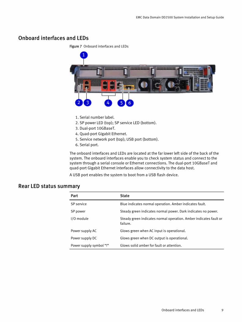
Onboard interfaces and LEDsFigure 7 Onboard interfaces and LEDs
1. Serial number label.2. SP power LED (top); SP service LED (bottom).3. Dual-port 10GBaseT.4. Quad-port Gigabit Ethernet.5. Service network port (top); USB port (bottom).6. Serial port.
The onboard interfaces and LEDs are located at the far lower left side of the back of thesystem. The onboard interfaces enable you to check system status and connect to thesystem through a serial console or Ethernet connections. The dual-port 10GBaseT andquad-port Gigabit Ethernet interfaces allow connectivity to the data host.
A USB port enables the system to boot from a USB flash device.
Rear LED status summary
Part State
SP service Blue indicates normal operation. Amber indicates fault.
SP power Steady green indicates normal power. Dark indicates no power.
I/O module Steady green indicates normal operation. Amber indicates fault orfailure.
Power supply AC Glows green when AC input is operational.
Power supply DC Glows green when DC output is operational.
Power supply symbol “!” Glows solid amber for fault or attention.
EMC Data Domain DD2500 System Installation and Setup Guide
Onboard interfaces and LEDs 9
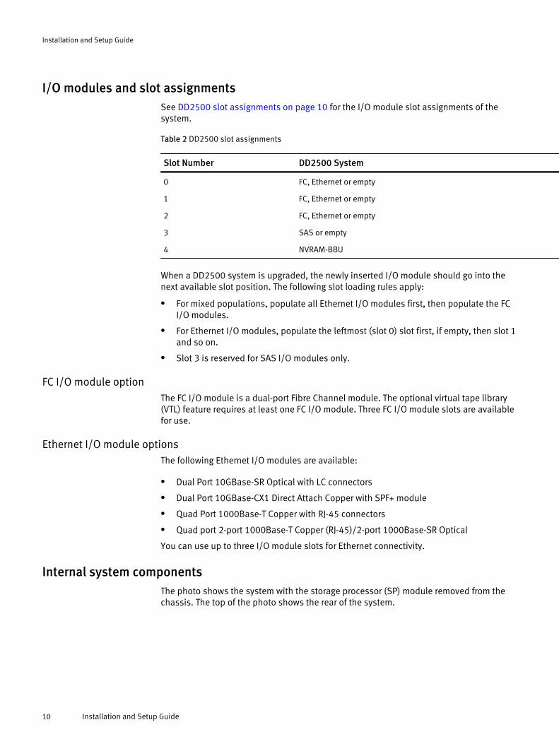
I/O modules and slot assignmentsSee DD2500 slot assignments on page 10 for the I/O module slot assignments of thesystem.
Table 2 DD2500 slot assignments
Slot Number DD2500 System
0 FC, Ethernet or empty
1 FC, Ethernet or empty
2 FC, Ethernet or empty
3 SAS or empty
4 NVRAM-BBU
When a DD2500 system is upgraded, the newly inserted I/O module should go into thenext available slot position. The following slot loading rules apply:
l For mixed populations, populate all Ethernet I/O modules first, then populate the FCI/O modules.
l For Ethernet I/O modules, populate the leftmost (slot 0) slot first, if empty, then slot 1and so on.
l Slot 3 is reserved for SAS I/O modules only.
FC I/O module optionThe FC I/O module is a dual-port Fibre Channel module. The optional virtual tape library(VTL) feature requires at least one FC I/O module. Three FC I/O module slots are availablefor use.
Ethernet I/O module optionsThe following Ethernet I/O modules are available:
l Dual Port 10GBase-SR Optical with LC connectors
l Dual Port 10GBase-CX1 Direct Attach Copper with SPF+ module
l Quad Port 1000Base-T Copper with RJ-45 connectors
l Quad port 2-port 1000Base-T Copper (RJ-45)/2-port 1000Base-SR Optical
You can use up to three I/O module slots for Ethernet connectivity.
Internal system componentsThe photo shows the system with the storage processor (SP) module removed from thechassis. The top of the photo shows the rear of the system.
Installation and Setup Guide
10 Installation and Setup Guide
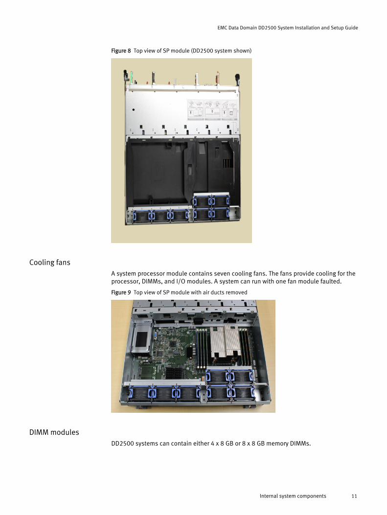
Figure 8 Top view of SP module (DD2500 system shown)
Cooling fansA system processor module contains seven cooling fans. The fans provide cooling for theprocessor, DIMMs, and I/O modules. A system can run with one fan module faulted.
Figure 9 Top view of SP module with air ducts removed
DIMM modulesDD2500 systems can contain either 4 x 8 GB or 8 x 8 GB memory DIMMs.
EMC Data Domain DD2500 System Installation and Setup Guide
Internal system components 11
Unpack the system1. Open the “Open Me First” box.
2. Remove the accessories and rack-mount kit from the shipping packages.
3. Remove the controller and bezel from the shipping packages.
Install the rack bracketsData Domain systems are installed into racks using the rack bracket hardware.
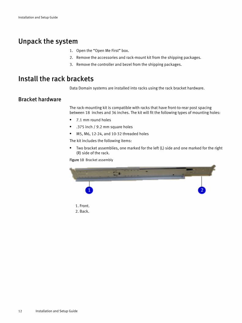
Bracket hardwareThe rack-mounting kit is compatible with racks that have front-to-rear post spacingbetween 18 inches and 36 inches. The kit will fit the following types of mounting holes:
l 7.1 mm round holes
l .375 inch / 9.2 mm square holes
l M5, M6, 12-24, and 10-32 threaded holes
The kit includes the following items:
l Two bracket assemblies, one marked for the left (L) side and one marked for the right(R) side of the rack.
Figure 10 Bracket assembly
1. Front.2. Back.
Installation and Setup Guide
12 Installation and Setup Guide
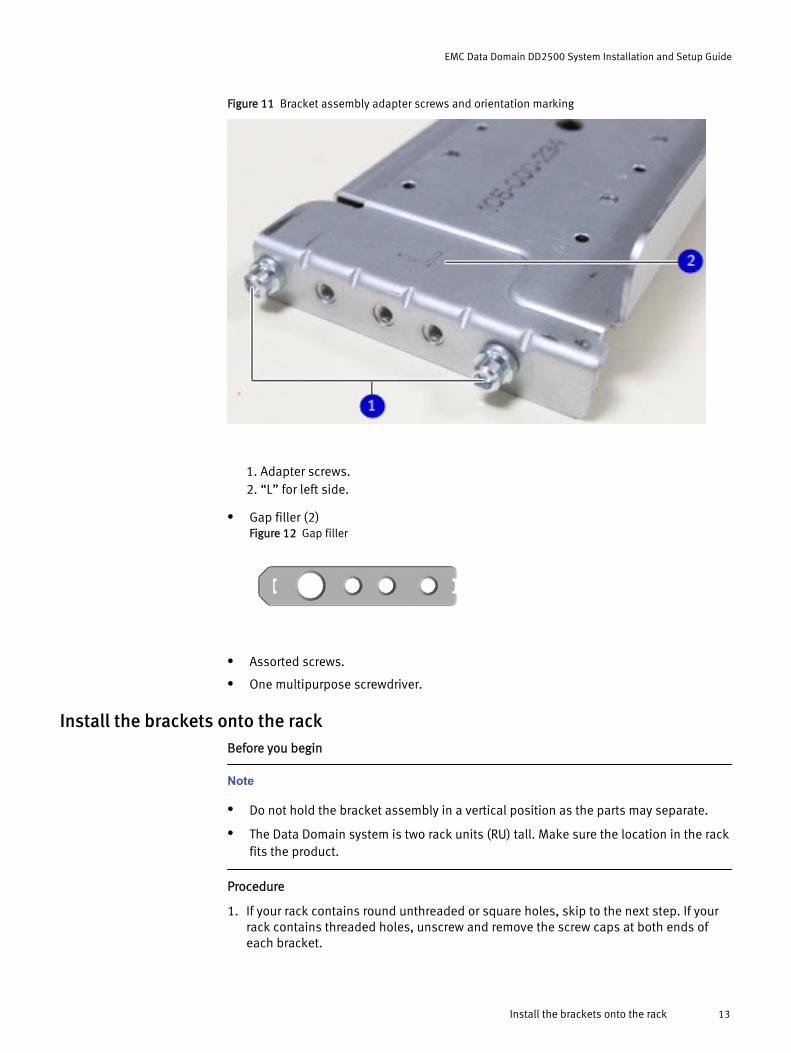
Figure 11 Bracket assembly adapter screws and orientation marking
1. Adapter screws.2. “L” for left side.
l Gap filler (2)Figure 12 Gap filler
l Assorted screws.
l One multipurpose screwdriver.
Install the brackets onto the rackBefore you begin
Note
l Do not hold the bracket assembly in a vertical position as the parts may separate.
l The Data Domain system is two rack units (RU) tall. Make sure the location in the rackfits the product.
Procedure
1. If your rack contains round unthreaded or square holes, skip to the next step. If yourrack contains threaded holes, unscrew and remove the screw caps at both ends ofeach bracket.
EMC Data Domain DD2500 System Installation and Setup Guide
Install the brackets onto the rack 13
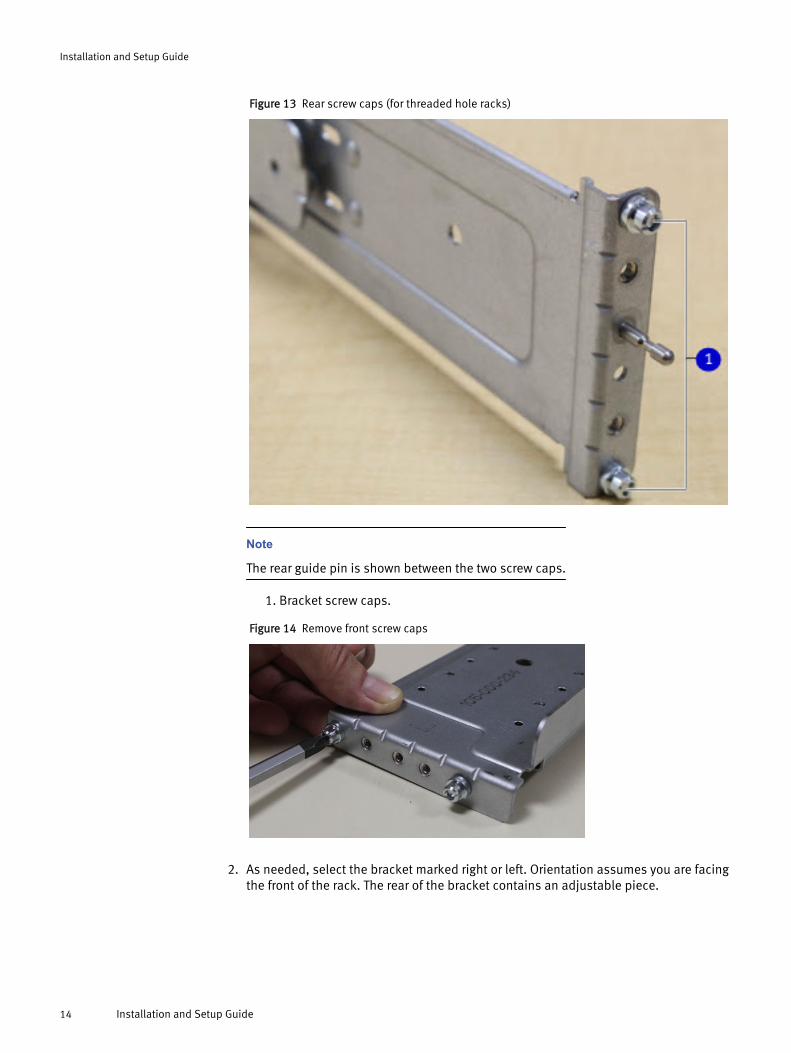
Figure 13 Rear screw caps (for threaded hole racks)
Note
The rear guide pin is shown between the two screw caps.
1. Bracket screw caps.
Figure 14 Remove front screw caps
2. As needed, select the bracket marked right or left. Orientation assumes you are facingthe front of the rack. The rear of the bracket contains an adjustable piece.
Installation and Setup Guide
14 Installation and Setup Guide
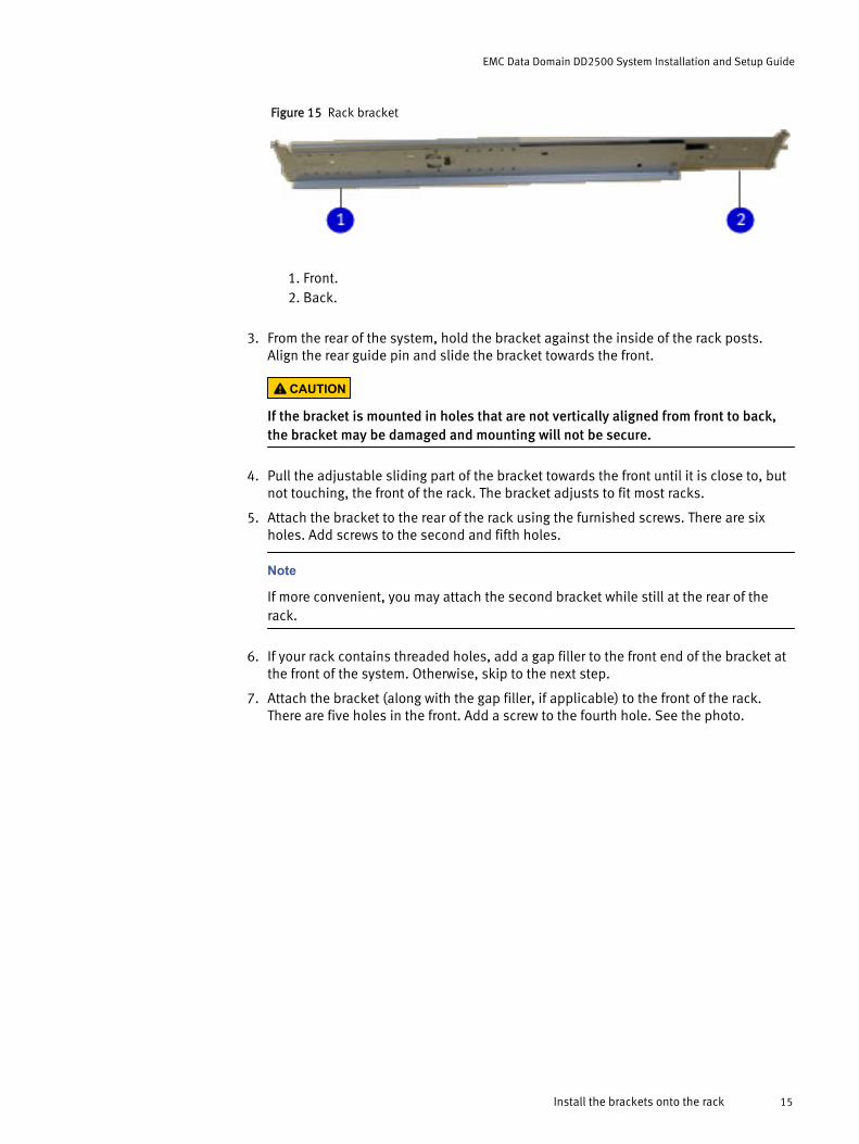
Figure 15 Rack bracket
1. Front.2. Back.
3. From the rear of the system, hold the bracket against the inside of the rack posts.Align the rear guide pin and slide the bracket towards the front.
CAUTION
If the bracket is mounted in holes that are not vertically aligned from front to back,the bracket may be damaged and mounting will not be secure.
4. Pull the adjustable sliding part of the bracket towards the front until it is close to, butnot touching, the front of the rack. The bracket adjusts to fit most racks.
5. Attach the bracket to the rear of the rack using the furnished screws. There are sixholes. Add screws to the second and fifth holes.
Note
If more convenient, you may attach the second bracket while still at the rear of therack.
6. If your rack contains threaded holes, add a gap filler to the front end of the bracket atthe front of the system. Otherwise, skip to the next step.
7. Attach the bracket (along with the gap filler, if applicable) to the front of the rack.There are five holes in the front. Add a screw to the fourth hole. See the photo.
EMC Data Domain DD2500 System Installation and Setup Guide
Install the brackets onto the rack 15
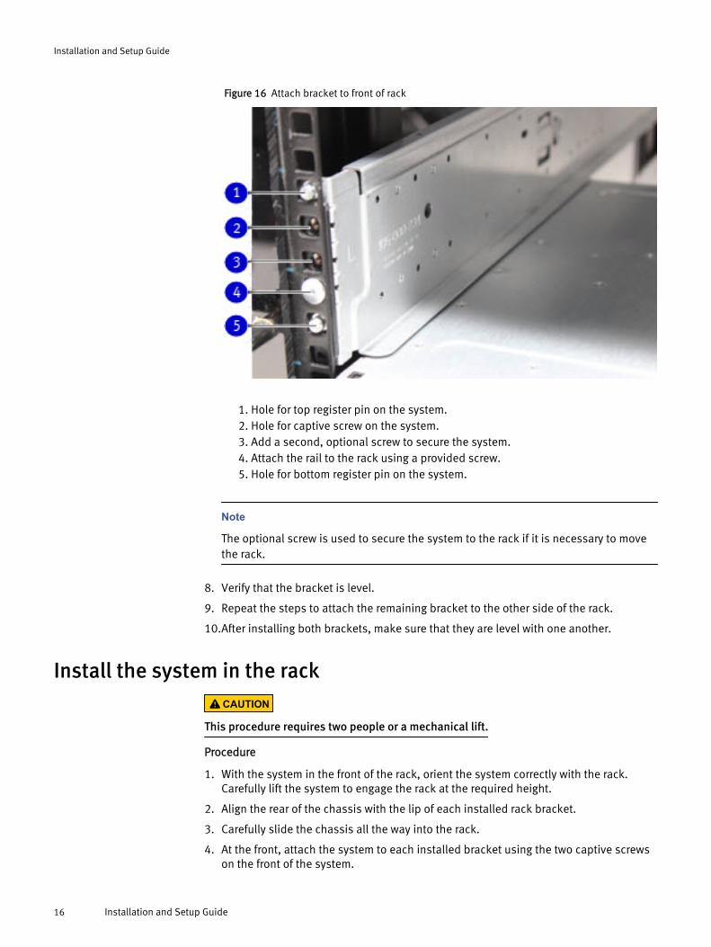
Figure 16 Attach bracket to front of rack
1. Hole for top register pin on the system.2. Hole for captive screw on the system.3. Add a second, optional screw to secure the system.4. Attach the rail to the rack using a provided screw.5. Hole for bottom register pin on the system.
Note
The optional screw is used to secure the system to the rack if it is necessary to movethe rack.
8. Verify that the bracket is level.
9. Repeat the steps to attach the remaining bracket to the other side of the rack.
10.After installing both brackets, make sure that they are level with one another.
Install the system in the rackCAUTION
This procedure requires two people or a mechanical lift.
Procedure
1. With the system in the front of the rack, orient the system correctly with the rack.Carefully lift the system to engage the rack at the required height.
2. Align the rear of the chassis with the lip of each installed rack bracket.
3. Carefully slide the chassis all the way into the rack.
4. At the front, attach the system to each installed bracket using the two captive screwson the front of the system.
Installation and Setup Guide
16 Installation and Setup Guide
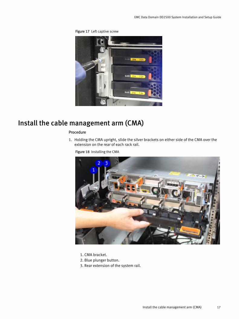
Figure 17 Left captive screw
Install the cable management arm (CMA)Procedure
1. Holding the CMA upright, slide the silver brackets on either side of the CMA over theextension on the rear of each rack rail.
Figure 18 Installing the CMA
1. CMA bracket.2. Blue plunger button.3. Rear extension of the system rail.
EMC Data Domain DD2500 System Installation and Setup Guide
Install the cable management arm (CMA) 17
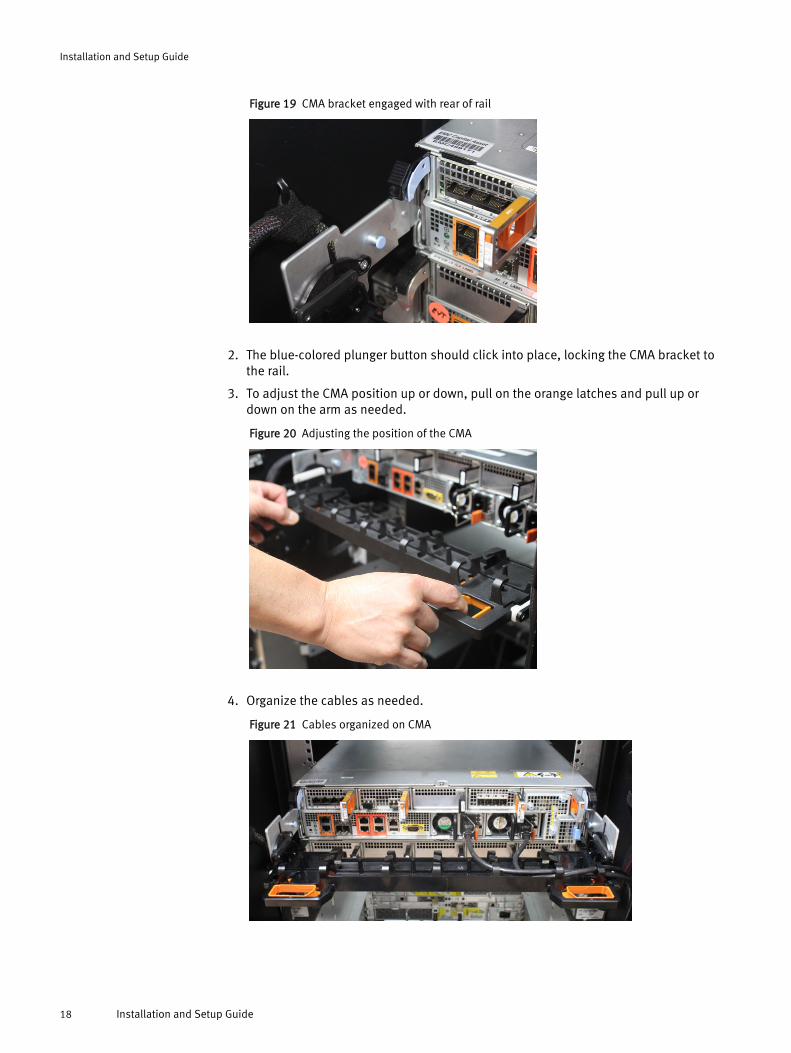
Figure 19 CMA bracket engaged with rear of rail
2. The blue-colored plunger button should click into place, locking the CMA bracket tothe rail.
3. To adjust the CMA position up or down, pull on the orange latches and pull up ordown on the arm as needed.
Figure 20 Adjusting the position of the CMA
4. Organize the cables as needed.
Figure 21 Cables organized on CMA
Installation and Setup Guide
18 Installation and Setup Guide
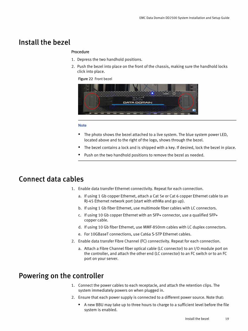
Install the bezelProcedure
1. Depress the two handhold positions.
2. Push the bezel into place on the front of the chassis, making sure the handhold locksclick into place.
Figure 22 Front bezel
Note
l The photo shows the bezel attached to a live system. The blue system power LED,located above and to the right of the logo, shows through the bezel.
l The bezel contains a lock and is shipped with a key. If desired, lock the bezel in place.
l Push on the two handhold positions to remove the bezel as needed.
Connect data cables1. Enable data transfer Ethernet connectivity. Repeat for each connection.
a. If using 1 Gb copper Ethernet, attach a Cat 5e or Cat 6 copper Ethernet cable to anRJ-45 Ethernet network port (start with ethMa and go up).
b. If using 1 Gb fiber Ethernet, use multimode fiber cables with LC connectors.
c. If using 10 Gb copper Ethernet with an SFP+ connector, use a qualified SFP+copper cable.
d. If using 10 Gb fiber Ethernet, use MMF-850nm cables with LC duplex connectors.
e. For 10GBaseT connections, use Cat6a S-STP Ethernet cables.
2. Enable data transfer Fibre Channel (FC) connectivity. Repeat for each connection.
a. Attach a Fibre Channel fiber optical cable (LC connector) to an I/O module port onthe controller, and attach the other end (LC connector) to an FC switch or to an FCport on your server.
Powering on the controller1. Connect the power cables to each receptacle, and attach the retention clips. The
system immediately powers on when plugged in.
2. Ensure that each power supply is connected to a different power source. Note that:
l A new BBU may take up to three hours to charge to a sufficient level before the filesystem is enabled.
EMC Data Domain DD2500 System Installation and Setup Guide
Install the bezel 19
l If the battery is good, but the system will not boot, or if the battery is failing tocharge, contact EMC Data Domain Technical Support.
Enable administrative communication
Note
See the DD2500 back panel on page 7 for the locations of the onboard interfaces.
1. Connect an administrative console to the serial port on the back panel of the system.
2. Launch a terminal emulation program from your computer and configure the followingcommunication settings:
Setting Value
Baud rate 9600
Data bits 8
Stop bits 1
Parity None
Flow control None
Emulation VT-100
3. Log into the CLI as the sysadmin user.
localhost.localdomain login: sysadminPassword: <system_serial_number>
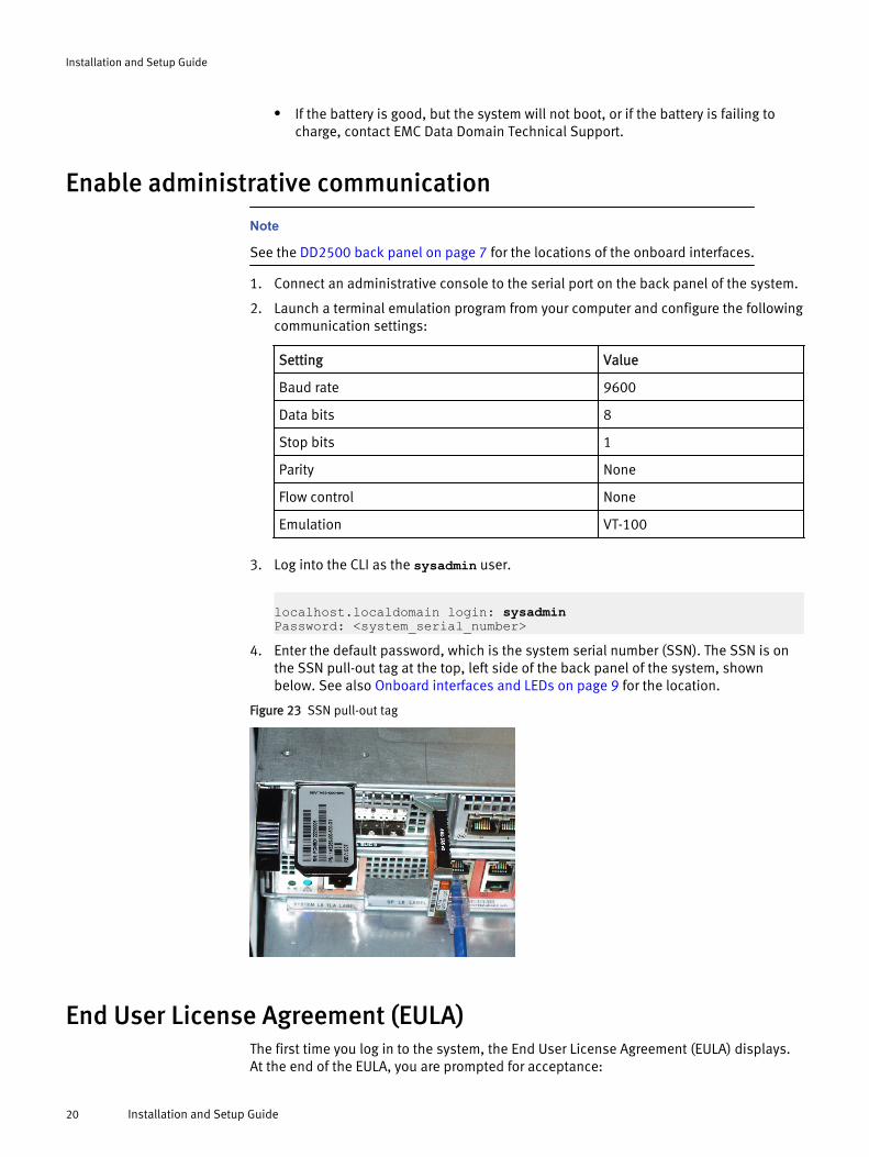
4. Enter the default password, which is the system serial number (SSN). The SSN is onthe SSN pull-out tag at the top, left side of the back panel of the system, shownbelow. See also Onboard interfaces and LEDs on page 9 for the location.
Figure 23 SSN pull-out tag
End User License Agreement (EULA)The first time you log in to the system, the End User License Agreement (EULA) displays.At the end of the EULA, you are prompted for acceptance:
Installation and Setup Guide
20 Installation and Setup Guide
Press any key then hit enter to acknowledge the receipt of EULA information:
Customer acceptance is required.
Note
An EMC representative should not accept the agreement. If a customer is not present toaccept the EULA, press Ctrl-C to exit from the EULA acceptance screen and continue theinstallation. Later, the customer can enter the system show eula command toredisplay the EULA and accept it.
Run the configuration wizardThe CLI configuration wizard starts automatically the first time the system boots. Thewizard prompts you through a series of questions that provide just enough informationfor initial system configuration and basic network connectivity.
Note
You can initiate the CLI configuration wizard manually by entering the config setupcommand.
Configuring the networkProcedure
1. Enter yes to begin configuring the system.
Do you want to configure system using GUI wizard (yes|no) [no]: yes
Answering yes initiates a shortened version of the CLI configuration wizard thatprovides enough information to configure the system for network access. Afterward,you can use the GUI (Data Domain System Manager) for additional configuration.Answering no initiates a longer, more robust, version of the CLI configuration wizard.
2. Enter yes and change the password.
Note
If you are an EMC internal resource or partner, do not change the password unlessspecifically directed to do so by the customer.
Change the 'sysadmin' password at this time? (yes|no):3. Enter yes to configure the system for network connectivity.
Network ConfigurationConfigure Network at this time (yes|no) [no]: yes
4. Enter yes to configure DHCP to obtain network parameters (such as, the hostname,domain name, and IP addresses) dynamically from a DHCP server. Or enter no toconfigure the parameters manually.
Use DHCPUse DHCP for hostname, domainname, default gateway andDNS servers? (At least one interface needs to be configuredusing DHCP) (yes|no|?)
EMC Data Domain DD2500 System Installation and Setup Guide
Run the configuration wizard 21
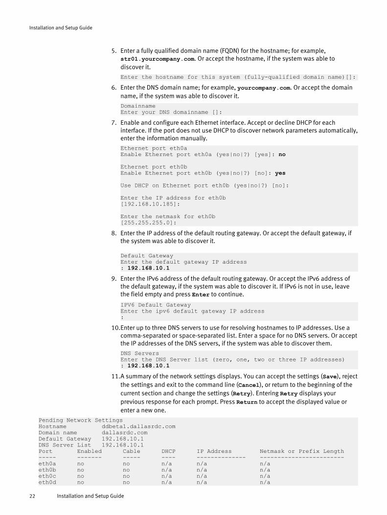
5. Enter a fully qualified domain name (FQDN) for the hostname; for example,str01.yourcompany.com. Or accept the hostname, if the system was able todiscover it.
Enter the hostname for this system (fully-qualified domain name)[]:6. Enter the DNS domain name; for example, yourcompany.com. Or accept the domain
name, if the system was able to discover it.
DomainnameEnter your DNS domainname []:
7. Enable and configure each Ethernet interface. Accept or decline DHCP for eachinterface. If the port does not use DHCP to discover network parameters automatically,enter the information manually.
Ethernet port eth0aEnable Ethernet port eth0a (yes|no|?) [yes]: no
Ethernet port eth0bEnable Ethernet port eth0b (yes|no|?) [no]: yes
Use DHCP on Ethernet port eth0b (yes|no|?) [no]: Enter the IP address for eth0b[192.168.10.185]:
Enter the netmask for eth0b[255.255.255.0]:
8. Enter the IP address of the default routing gateway. Or accept the default gateway, ifthe system was able to discover it.
Default GatewayEnter the default gateway IP address: 192.168.10.1
9. Enter the IPv6 address of the default routing gateway. Or accept the IPv6 address ofthe default gateway, if the system was able to discover it. If IPv6 is not in use, leavethe field empty and press Enter to continue.
IPV6 Default GatewayEnter the ipv6 default gateway IP address:
10.Enter up to three DNS servers to use for resolving hostnames to IP addresses. Use acomma-separated or space-separated list. Enter a space for no DNS servers. Or acceptthe IP addresses of the DNS servers, if the system was able to discover them.
DNS ServersEnter the DNS Server list (zero, one, two or three IP addresses): 192.168.10.1
11.A summary of the network settings displays. You can accept the settings (Save), rejectthe settings and exit to the command line (Cancel), or return to the beginning of thecurrent section and change the settings (Retry). Entering Retry displays yourprevious response for each prompt. Press Return to accept the displayed value orenter a new one.
Pending Network SettingsHostname ddbeta1.dallasrdc.comDomain name dallasrdc.com Default Gateway 192.168.10.1 DNS Server List 192.168.10.1 Port Enabled Cable DHCP IP Address Netmask or Prefix Length----- ------- ----- ---- -------------- ------------------------eth0a no no n/a n/a n/a eth0b no no n/a n/a n/a eth0c no no n/a n/a n/a eth0d no no n/a n/a n/a
Installation and Setup Guide
22 Installation and Setup Guide
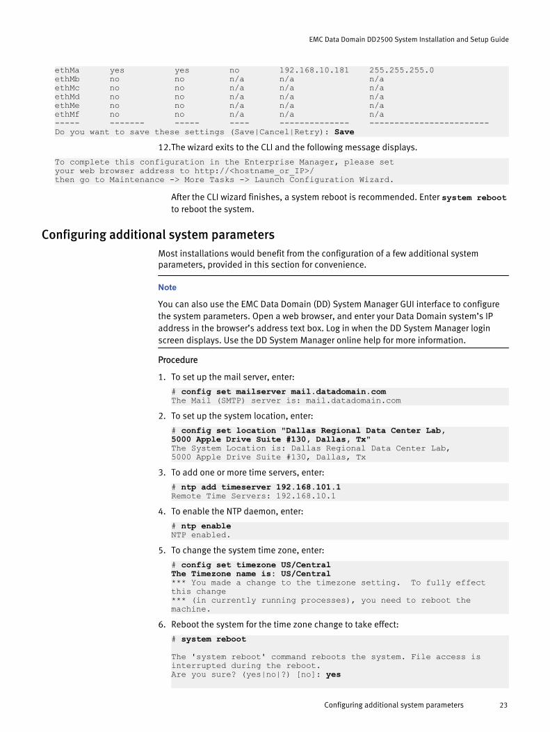
ethMa yes yes no 192.168.10.181 255.255.255.0 ethMb no no n/a n/a n/a ethMc no no n/a n/a n/a ethMd no no n/a n/a n/a ethMe no no n/a n/a n/a ethMf no no n/a n/a n/a ----- ------- ----- ---- -------------- ------------------------Do you want to save these settings (Save|Cancel|Retry): Save
12.The wizard exits to the CLI and the following message displays.
To complete this configuration in the Enterprise Manager, please set your web browser address to http://<hostname_or_IP>/ then go to Maintenance -> More Tasks -> Launch Configuration Wizard.
After the CLI wizard finishes, a system reboot is recommended. Enter system rebootto reboot the system.
Configuring additional system parametersMost installations would benefit from the configuration of a few additional systemparameters, provided in this section for convenience.
Note
You can also use the EMC Data Domain (DD) System Manager GUI interface to configurethe system parameters. Open a web browser, and enter your Data Domain system’s IPaddress in the browser’s address text box. Log in when the DD System Manager loginscreen displays. Use the DD System Manager online help for more information.
Procedure
1. To set up the mail server, enter:
# config set mailserver mail.datadomain.comThe Mail (SMTP) server is: mail.datadomain.com
2. To set up the system location, enter:
# config set location "Dallas Regional Data Center Lab,5000 Apple Drive Suite #130, Dallas, Tx"The System Location is: Dallas Regional Data Center Lab,5000 Apple Drive Suite #130, Dallas, Tx
3. To add one or more time servers, enter:
# ntp add timeserver 192.168.101.1Remote Time Servers: 192.168.10.1
4. To enable the NTP daemon, enter:
# ntp enableNTP enabled.
5. To change the system time zone, enter:
# config set timezone US/CentralThe Timezone name is: US/Central*** You made a change to the timezone setting. To fully effect this change *** (in currently running processes), you need to reboot the machine.
6. Reboot the system for the time zone change to take effect:
# system reboot
The 'system reboot' command reboots the system. File access is interrupted during the reboot.Are you sure? (yes|no|?) [no]: yes
EMC Data Domain DD2500 System Installation and Setup Guide
Configuring additional system parameters 23

ok, proceeding.The system is going down for reboot.
7. After the system completes the reboot, login again as sysadmin using the serialnumber as a password. Press Ctrl-C to get through the EULA, sysadmin passwordprompt, and config setup wizard.
8. Generate an autosupport sent to yourself to use as ACG input
# autosupport send [email protected]: Message sent.
9. Generate an ACG using the produced ASUP.
Installation and Setup Guide
24 Installation and Setup Guide

Copyright © 2014-2015 EMC Corporation. All rights reserved. Published in USA.
Published February, 2015
EMC believes the information in this publication is accurate as of its publication date. The information is subject to change withoutnotice.
The information in this publication is provided as is. EMC Corporation makes no representations or warranties of any kind withrespect to the information in this publication, and specifically disclaims implied warranties of merchantability or fitness for aparticular purpose. Use, copying, and distribution of any EMC software described in this publication requires an applicable softwarelicense.
EMC², EMC, and the EMC logo are registered trademarks or trademarks of EMC Corporation in the United States and other countries.All other trademarks used herein are the property of their respective owners.
For the most up-to-date regulatory document for your product line, go to EMC Online Support (https://support.emc.com).
EMC Data Domain DD2500 System Installation and Setup Guide
Configuring additional system parameters 25