Embed Size (px)
Citation preview
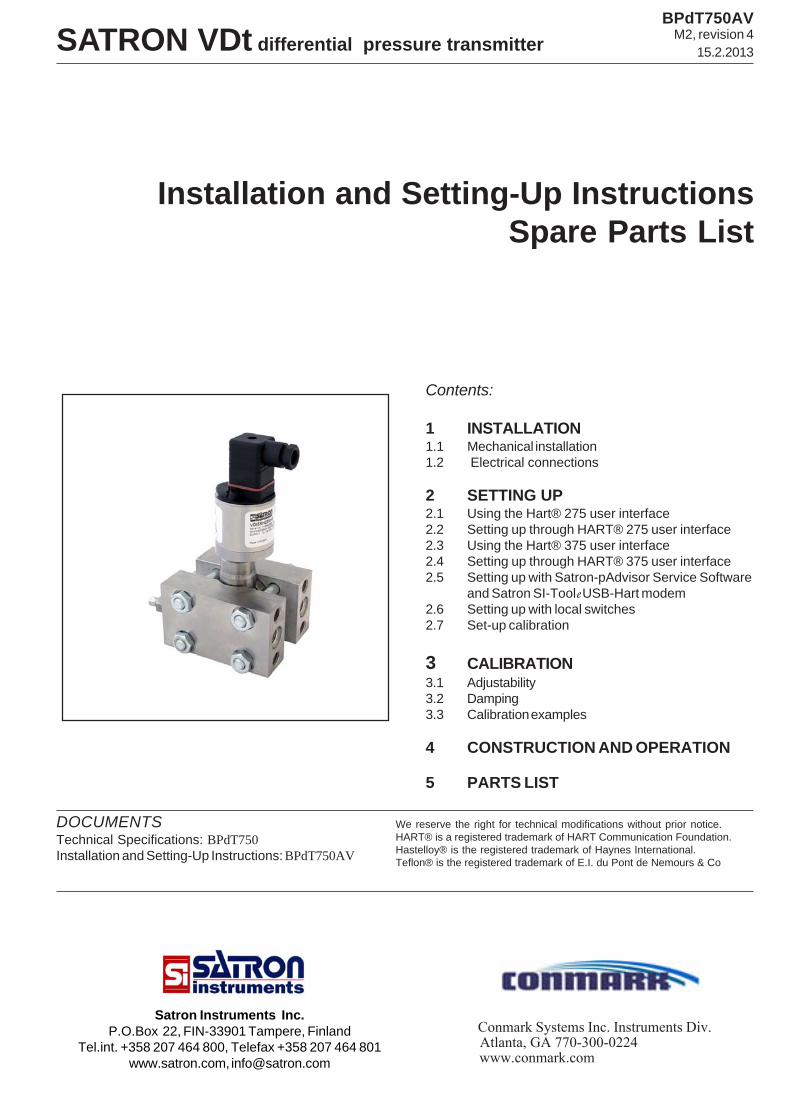
SATRON VDt differential pressure transmitter
Installation and Setting-Up InstructionsSpare Parts List
Contents:
1 INSTALLATION1.1 Mechanical installation1.2 Electrical connections
2 SETTING UP2.1 Using the Hart® 275 user interface2.2 Setting up through HART® 275 user interface2.3 Using the Hart® 375 user interface2.4 Setting up through HART® 375 user interface2.5 Setting up with Satron-pAdvisor Service Software
and Satron SI-Toole USB-Hart modem2.6 Setting up with local switches2.7 Set-up calibration
3 CALIBRATION3.1 Adjustability3.2 Damping3.3 Calibration examples
4 CONSTRUCTION AND OPERATION
5 PARTS LIST
DOCUMENTSTechnical Specifications: BPdT750Installation and Setting-Up Instructions: BPdT750AV
BPdT750AVM2, revision 4
15.2.2013
We reserve the right for technical modifications without prior notice.HART® is a registered trademark of HART Communication Foundation.Hastelloy® is the registered trademark of Haynes International.Teflon® is the registered trademark of E.I. du Pont de Nemours & Co
Satron Instruments Inc.P.O.Box 22, FIN-33901 Tampere, Finland
Tel.int. +358 207 464 800, Telefax +358 207 464 801www.satron.com, [email protected]
Conmark Systems Inc. Instruments Div. Atlanta, GA 770-300-0224www.conmark.com
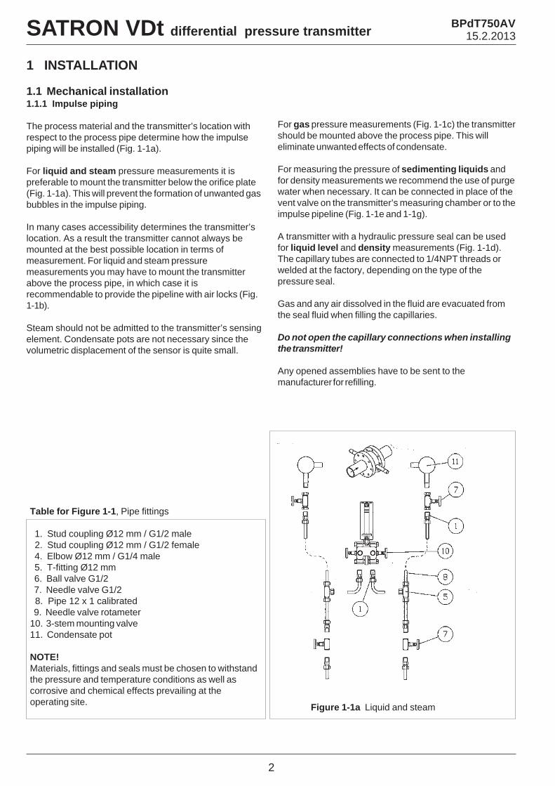
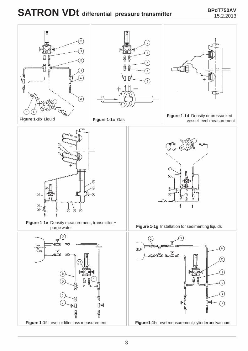
For gas pressure measurements (Fig. 1-1c) the transmittershould be mounted above the process pipe. This willeliminate unwanted effects of condensate.
For measuring the pressure of sedimenting liquids andfor density measurements we recommend the use of purgewater when necessary. It can be connected in place of thevent valve on the transmitter’s measuring chamber or to theimpulse pipeline (Fig. 1-1e and 1-1g).
A transmitter with a hydraulic pressure seal can be usedfor liquid level and density measurements (Fig. 1-1d).The capillary tubes are connected to 1/4NPT threads orwelded at the factory, depending on the type of thepressure seal.
Gas and any air dissolved in the fluid are evacuated fromthe seal fluid when filling the capillaries.
Do not open the capillary connections when installingthe transmitter!
Any opened assemblies have to be sent to themanufacturer for refilling.
2
Table for Figure 1-1, Pipe fittings
1. Stud coupling Ø12 mm / G1/2 male 2. Stud coupling Ø12 mm / G1/2 female 4. Elbow Ø12 mm / G1/4 male 5. T-fitting Ø12 mm 6. Ball valve G1/2 7. Needle valve G1/2 8. Pipe 12 x 1 calibrated 9. Needle valve rotameter10. 3-stem mounting valve11. Condensate pot
NOTE!Materials, fittings and seals must be chosen to withstandthe pressure and temperature conditions as well ascorrosive and chemical effects prevailing at theoperating site. Figure 1-1a Liquid and steam
1 INSTALLATION
1.1 Mechanical installation1.1.1 Impulse piping
The process material and the transmitter’s location withrespect to the process pipe determine how the impulsepiping will be installed (Fig. 1-1a).
For liquid and steam pressure measurements it ispreferable to mount the transmitter below the orifice plate(Fig. 1-1a). This will prevent the formation of unwanted gasbubbles in the impulse piping.
In many cases accessibility determines the transmitter’slocation. As a result the transmitter cannot always bemounted at the best possible location in terms ofmeasurement. For liquid and steam pressuremeasurements you may have to mount the transmitterabove the process pipe, in which case it isrecommendable to provide the pipeline with air locks (Fig.1-1b).
Steam should not be admitted to the transmitter’s sensingelement. Condensate pots are not necessary since thevolumetric displacement of the sensor is quite small.
SATRON VDt differential pressure transmitter BPdT750AV15.2.2013
3
Figure 1-1b Liquid Figure 1-1c GasFigure 1-1d Density or pressurized vessel level measurement
Figure 1-1g Installation for sedimenting liquidsFigure 1-1e Density measurement, transmitter +
purge water
Figure 1-1f Level or filter loss measurement Figure 1-1h Level measurement, cylinder and vacuum
SATRON VDt differential pressure transmitter BPdT750AV15.2.2013
Ø18.5
2.5
14.5
1/4-18 NPSF
A - A
0+0.3
0+0.5
A A
4
SATRON VDt differential pressure transmitter BPdT750AV15.2.2013
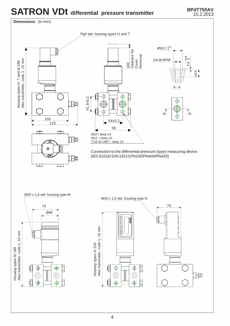
Dimensions (in mm)
100125
Pg9 std. housing types H and T
96
54±0,2
41,3
±0,2
M10 / deep 14M12 / deep 147/16-20 UNF / deep 14
Hou
sing
type
s H
, T a
nd M
188
Ate
x tra
nsm
itter
, cod
e 1,
15
mm
100
Cle
arac
e fo
rC
over
Rem
oval
Hou
sing
type
s M
188
Ate
x tra
nsm
itter
, cod
e 1,
15
mm
Hou
sing
type
s N
218
Ate
x tra
nsm
itter
, cod
e 1,
15
mm
75
Ø48
70
M20 x 1,5 std. housing type MM20 x 1,5 std. housing type N
Esc
Enter
Connection to the differential pressure (type) measuring device(IEC 61518 / DIN 19213 PN100/PN400/PN420)
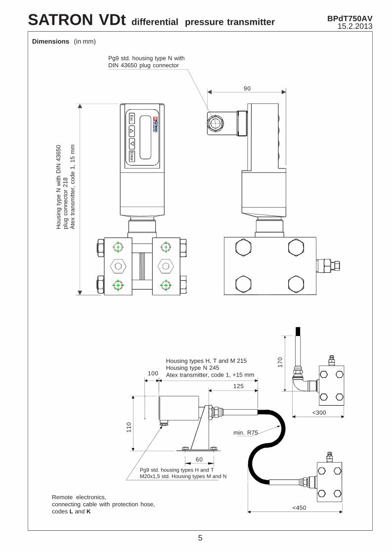
Remote electronics,connecting cable with protection hose,codes L and K
Pg9 std. housing types H and TM20x1,5 std. Housing types M and N
60
100
125
<450
<300
min. R75
Housing types H, T and M 215Housing type N 245Atex transmitter, code 1, +15 mm
110
170
Dimensions (in mm)
90
Pg9 std. housing type N withDIN 43650 plug connector
Hou
sing
type
N w
ith D
IN 4
3650
plug
con
nect
or 2
18A
tex
trans
mitt
er, c
ode
1, 1
5 m
m
EscEnter
BPdT750AV15.2.2013SATRON VDt differential pressure transmitter
5
6
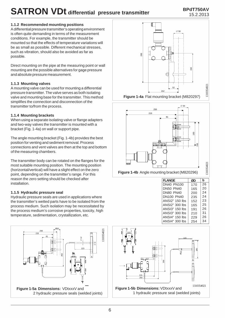
Figure 1-4a Flat mounting bracket (M820297)
1.1.2 Recommended mounting positionsA differential pressure transmitter’s operating environmentis often quite demanding in terms of the measurementconditions. For example, the transmitter should bemounted so that the effects of temperature variations willbe as small as possible. Different mechanical stresses,such as vibration, should also be avoided as far aspossible.
Direct mounting on the pipe at the measuring point or wallmounting are the possible alternatives for gage pressureand absolute pressure measurement.
1.1.3 Mounting valvesA mounting valve can be used for mounting a differentialpressure transmitter. The valve serves as both isolatingvalve and mounting base for the transmitter. This methodsimplifies the connection and disconnection of thetransmitter to/from the process.
1.1.4 Mounting bracketsWhen using a separate isolating valve or flange adaptersand two-way valves the transmitter is mounted with abracket (Fig. 1-4a) on wall or support pipe.
The angle mounting bracket (Fig. 1-4b) provides the bestposition for venting and sediment removal. Processconnections and vent valves are then at the top and bottomof the measuring chambers.
The transmitter body can be rotated on the flanges for themost suitable mounting position. The mounting position(horizontal/vertical) will have a slight effect on the zeropoint, depending on the transmitter’s range. For thisreason the zero setting should be checked afterinstallation.
1.1.5 Hydraulic pressure sealHydraulic pressure seals are used in applications wherethe transmitter’s wetted parts have to be isolated from theprocess medium. Such isolation may be necessitated bythe process medium’s corrosive properties, toxicity, hightemperature, sedimentation, crystallization, etc.
Figure 1-4b Angle mounting bracket (M820296)
Figure 1-5a Dimensions: VDtxxxV and 2 hydraulic pressure seals (welded joints)
Figure 1-5b Dimensions: VDtxxxV and 1 hydraulic pressure seal (welded joints)
FLANGEDN40 PN100DN50 PN40DN80 PN40DN100 PN40ANSI2" 150 lbsANSI2" 300 lbsANSI3" 150 lbsANSI3" 300 lbsANSI4" 150 lbsANSI4" 300 lbs
ØD170165200235152165191210229254
b26202424232526312634
SATRON VDt differential pressure transmitter BPdT750AV15.2.2013
1310
3540
2113
1035
4021
1310
3540
21
1310354021
250
215
250
∅ 50
81
150
52
150
152
285
∅ 50
∅ 1
2
∅ D
b
123
250215
250
81
Ø50
250215
250
123
b
ØD
Ø12
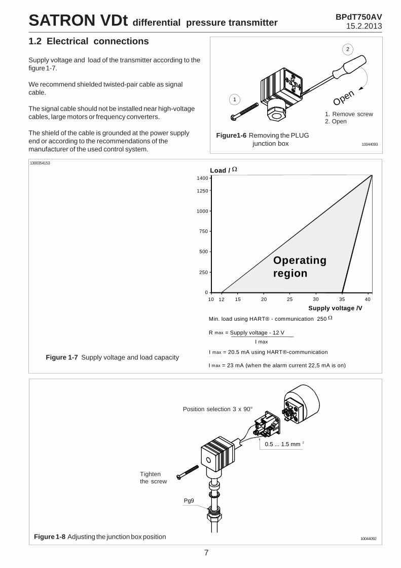
Figure 1-7 Supply voltage and load capacity
Figure 1-8 Adjusting the junction box position
Position selection 3 x 90°
Tightenthe screw
1.2 Electrical connections
Supply voltage and load of the transmitter according to thefigure 1-7.
We recommend shielded twisted-pair cable as signalcable.
The signal cable should not be installed near high-voltagecables, large motors or frequency converters.
The shield of the cable is grounded at the power supplyend or according to the recommendations of themanufacturer of the used control system.
1. Remove screw2. Open
Figure1-6 Removing the PLUG junction box
1
2
Open
0.5 ... 1.5 mm 2
Pg9
10044093
10044092
10 12 15 20 25 30 350
250
500
750
1000
1400
Supply voltage /V
Load / Ω
40
1250
Operatingregion
Min. load using HART® - communication 250 Ω
R max = Supply voltage - 12 V I max
I max = 20.5 mA using HART®-communication
I max = 23 mA (when the alarm current 22,5 mA is on)
1300354153
7
SATRON VDt differential pressure transmitter BPdT750AV15.2.2013
8
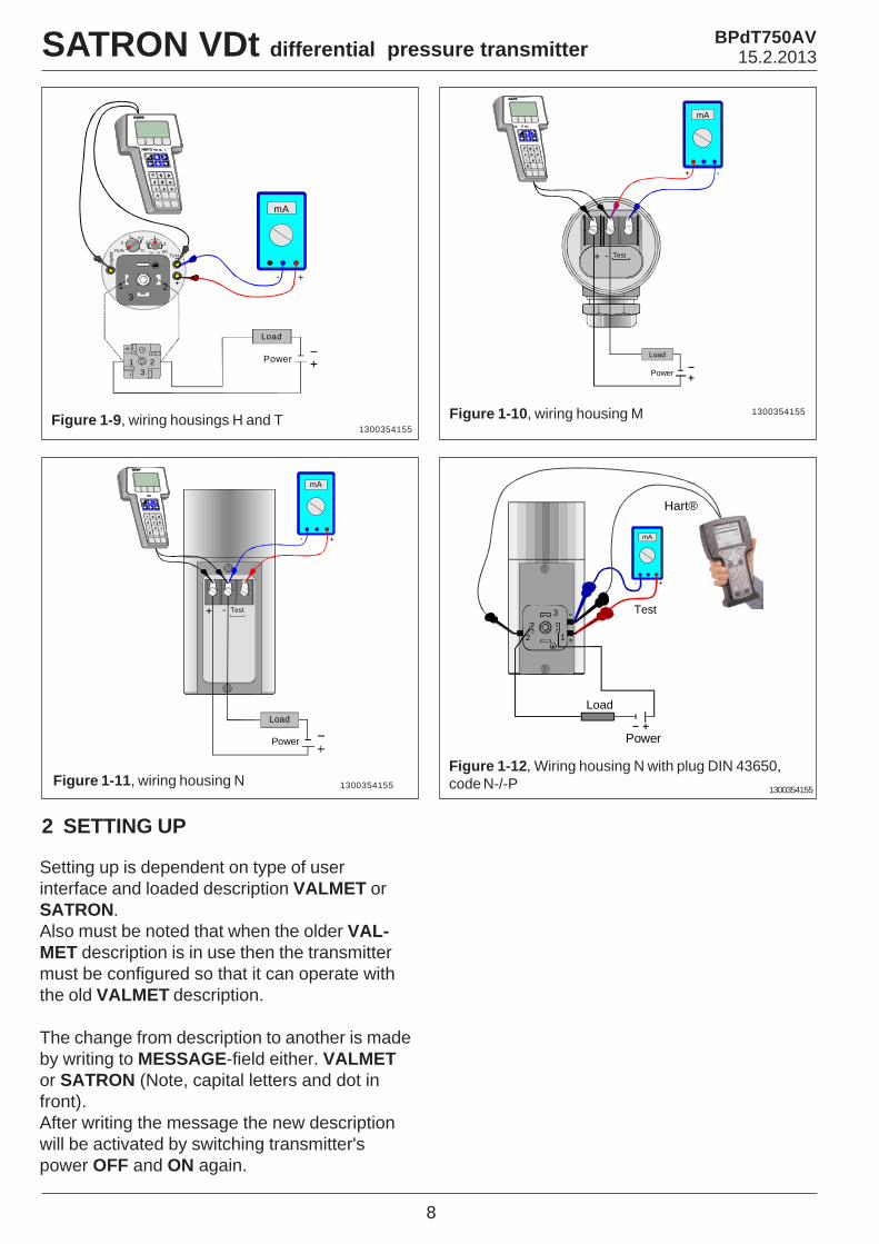
Figure 1-9, wiring housings H and T Figure 1-10, wiring housing M
Figure 1-11, wiring housing N
1300354155
1300354155
1300354155
+ - Test
mA
+ -
Power
Load
Har
t® Test
321
13
60
.5
DN UP
PZ
DRUN
ZS
13
21
2
Power
Load
mA
+-
SATRON VDt differential pressure transmitter BPdT750AV15.2.2013
2 SETTING UP
Setting up is dependent on type of userinterface and loaded description VALMET orSATRON.Also must be noted that when the older VAL-MET description is in use then the transmittermust be configured so that it can operate withthe old VALMET description.
The change from description to another is madeby writing to MESSAGE-field either. VALMETor SATRON (Note, capital letters and dot infront).After writing the message the new descriptionwill be activated by switching transmitter'spower OFF and ON again.
Figure 1-12, Wiring housing N with plug DIN 43650,code N-/-P 1300354155
+ - Test
Power
Load
mA
+-
Power
Load
12
3 Test
mA
+-
Hart®
2.2 Setting up through HART® 275 userinterface
After installing and connecting the transmitter, connect theuser interface to the transmitter. The following menu isdisplayed:
1 Measurement2 Configuration3 Information4 Diagnostics
To change the measuring range, unit damping time constantto output mode (linear/square-root), select Configuration.
The following menu is then displayed:
1 Range values2 Detailed config
To change the measuring range, select Range values.
The selection displays the following menu:1 LRV (lower range value)2 URV (upper range value)3 LSL (lower sensor limit)4 USL (upper sensor limit)5 Min span (minimum span)6 Apply values
To change the measurement unit, damping time constant oroutput mode, select Detailed config from the Configura-tion menu.
The selection displays the following menu:1 Damping2 Pres. unit3 Tempr. unit4 Alarm current5 Write protect6 Lin. func7 Diff El status8 Burst mode9 Burst option Poll addr Tag User function User funct. setup
After these activities or if the transmitter is supplied with theready configuration you must correct a zero error of thetransmitter in a final installation position.
Press Diagnostics and PV Zero calibr.
The selection displays the following menu: Give correctvalue for Zero pressure in ...
The current zero point will be shown in display and the finalzero error correction can be done.
9
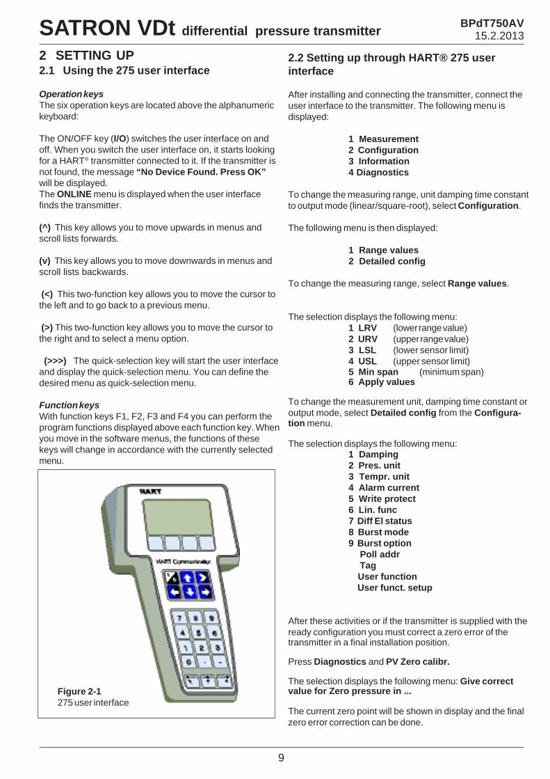
2 SETTING UP2.1 Using the 275 user interface
Operation keysThe six operation keys are located above the alphanumerickeyboard:
The ON/OFF key (I/O) switches the user interface on andoff. When you switch the user interface on, it starts lookingfor a HART® transmitter connected to it. If the transmitter isnot found, the message “No Device Found. Press OK”will be displayed.The ONLINE menu is displayed when the user interfacefinds the transmitter.
(^) This key allows you to move upwards in menus andscroll lists forwards.
(v) This key allows you to move downwards in menus andscroll lists backwards.
(<) This two-function key allows you to move the cursor tothe left and to go back to a previous menu.
(>) This two-function key allows you to move the cursor tothe right and to select a menu option.
(>>>) The quick-selection key will start the user interfaceand display the quick-selection menu. You can define thedesired menu as quick-selection menu.
Function keysWith function keys F1, F2, F3 and F4 you can perform theprogram functions displayed above each function key. Whenyou move in the software menus, the functions of thesekeys will change in accordance with the currently selectedmenu.
Figure 2-1275 user interface
SATRON VDt differential pressure transmitter BPdT750AV15.2.2013
10
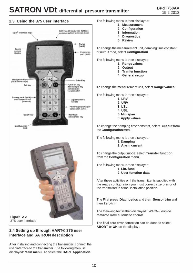
2.4 Setting up through HART® 375 userinterface and SATRON description
After installing and connecting the transmitter, connect theuser interface to the transmitter. The following menu isdisplayed: Main menu. To select the HART Application.
Figure 2-2375 user interface
2.3 Using the 375 user interface The following menu is then displayed:1 Measurement2 Configuration3 Information4 Diagnostics5 Review
To change the measurement unit, damping time constantor output mod, select Configuration.
The following menu is then displayed:1 Range values2 Output3 Tranfer function4 General setup
To change the measurement unit, select Range values.
The following menu is then displayed:1 LRV2 URV3 LSL4 USL5 Min span6 Apply values
To change the damping time constant, select Output fromthe Configuration menu.
The following menu is then displayed:1 Damping2 Alarm current
To change the output mode, select Transfer functionfrom the Configuration menu.
The following menu is then displayed:1 Lin. func2 User function data
After these activities or if the transmitter is supplied withthe ready configuration you must correct a zero error ofthe transmitter in a final installation position.
The First press Diagnostics and then Sensor trim andthen Zero trim
The following text is then displayed : WARN-Loop beremoved from automatic control
The final zero error correction can be done to selectABORT or OK on the display .
BPdT750AV15.2.2013SATRON VDt differential pressure transmitter
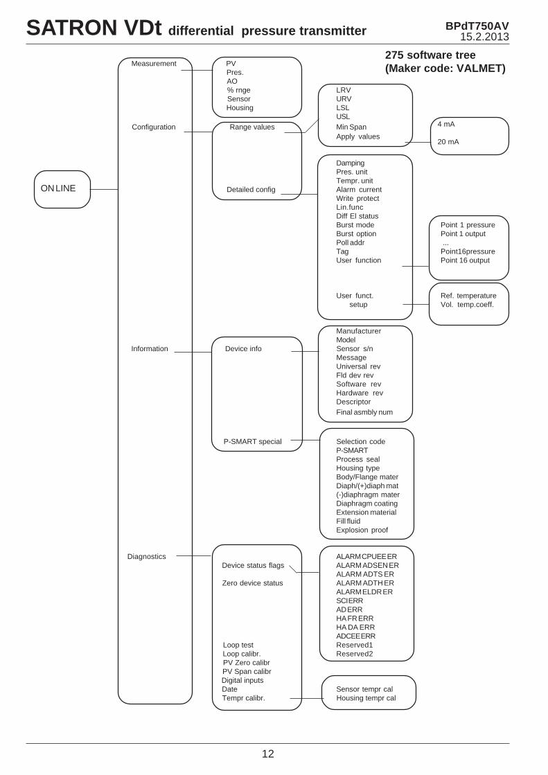
2.6 Setting-up with local switches
The additional instruction of display menus is enclosed tothis manual.
Figure 2-4 VDt differential pressure transmitter with display 1300354154
Keyboard :Esc = Press Esc move back towards the top of the main menu.
= Use the UP arrow key to move up on the current menulevel or to increase the selected parameter value.
= Use the DOWN arrow key to move down on the currentmenu level or to decrease the selected parameter value.
Enter = Press ENTER to move to a lower level in a menu or toaccept a command or parameter value.
SATRON VDt differential pressure transmitter
11
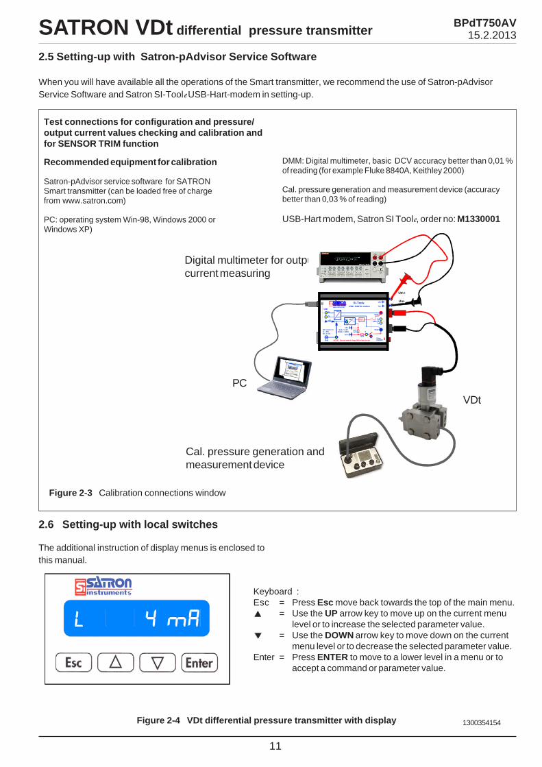
2.5 Setting-up with Satron-pAdvisor Service Software
When you will have available all the operations of the Smart transmitter, we recommend the use of Satron-pAdvisorService Software and Satron SI-Toole USB-Hart-modem in setting-up.
Figure 2-3 Calibration connections window
Test connections for configuration and pressure/output current values checking and calibration andfor SENSOR TRIM function
Recommended equipment for calibration
Satron-pAdvisor service software for SATRONSmart transmitter (can be loaded free of chargefrom www.satron.com)
PC: operating system Win-98, Windows 2000 orWindows XP)
DMM: Digital multimeter, basic DCV accuracy better than 0,01 %of reading (for example Fluke 8840A, Keithley 2000)
Cal. pressure generation and measurement device (accuracybetter than 0,03 % of reading)
USB-Hart modem, Satron SI Toole, order no: M1330001
PC
Cal. pressure generation andmeasurement device
VDt
Digital multimeter for outputcurrent measuring
BPdT750AV15.2.2013
Rx
Rx
Tx
Tx+5V
Ext. power in 9... 30VDC or AC
USBUSB
HA RT + 24V -
Pwr OKHART
Vsup+
Vsup-
VsupON/OFF
Um-
I100R0.01%
Um+L
150R
Si-Toolewww.satron.com
4mA = 0.4V 20mA = 2VDC
R
USB / HART modemR Um-
Um+
NOTE! Do not switch Vsup ON in live circuitIP40
28mA
Um+
Um-
Measurement PV Pres. AO % rnge LRV Sensor URV Housing LSL
USL Configuration Range values Min Span
Apply values
DampingPres. unitTempr. unit
Detailed config Alarm currentWrite protectLin.funcDiff El statusBurst mode Point 1 pressureBurst option Point 1 outputPoll addr ...Tag Point16pressureUser function Point 16 output
User funct. Ref. temperature setup Vol. temp.coeff.
ManufacturerModel
Information Device info Sensor s/nMessageUniversal revFld dev revSoftware revHardware revDescriptorFinal asmbly num
P-SMART special Selection codeP-SMARTProcess sealHousing typeBody/Flange materDiaph/(+)diaph mat(-)diaphragm materDiaphragm coatingExtension materialFill fluidExplosion proof
Diagnostics ALARM CPUEE ER Device status flags ALARM ADSEN ER
ALARM ADTS ER Zero device status ALARM ADTH ER
ALARM ELDR ERSCI ERRAD ERRHA FR ERRHA DA ERRADCEE ERR
Loop test Reserved1 Loop calibr. Reserved2 PV Zero calibr PV Span calibr Digital inputs Date Sensor tempr cal Tempr calibr. Housing tempr cal
12
4 mA
20 mA
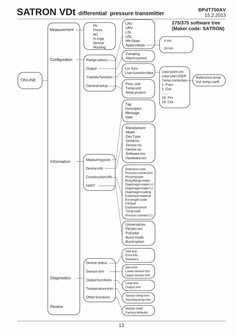
ON LINE
275 software tree(Maker code: VALMET)
SATRON VDt differential pressure transmitter BPdT750AV15.2.2013
13
4 mA
20 mA
275/375 software tree(Maker code: SATRON)
ON LINE
Measurement
Configuration
Information
Diagnostics
Review
PVPressAO% rngeSensorHousing
Range values
Output
Transfer function
General setup
LRVURVLSLUSLMin SpanApply values
DampingAlarm current
Lin. funcUser function data
Pres. unitTemp unitWrite protect
User point cntUser unit USERTemp correction1. Pres1. Out......16. Prs16. Out
Reference tempVol. temp coeff.
Measuring point
Device info
Construction info
HART
TagDescriptorMessageDate
ManufacturerModelDev TypeSerial no.Sensor no.Device no.Software revHardware rev
Selection codeProcess connectionHousing typeBody/flange materDiaphragm mater (+)Diaphragm mater (-)Diaphragm coatingExtension materialExt lenght codeFill fluidExplosion proofTemp codeProcess connect (-)
Universal revFld dev revPoll addrBurst modeBurst option
Device status
Sensor trim
Output functions
Temperature trim
Other functions
Self testError infoStatistics
Zero trimLower sensor trimUpper sensor trim
Loop testOutput trim
Sensor temp trimHousing temp trim
Master resetFactory defaults
SATRON VDt differential pressure transmitter BPdT750AV15.2.2013
Housing with PLUG-connector, code T
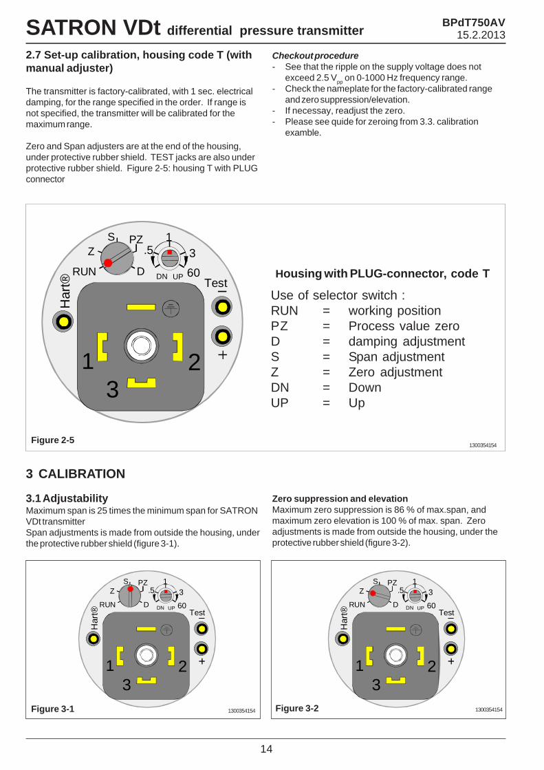
2.7 Set-up calibration, housing code T (withmanual adjuster)
The transmitter is factory-calibrated, with 1 sec. electricaldamping, for the range specified in the order. If range isnot specified, the transmitter will be calibrated for themaximum range.
Zero and Span adjusters are at the end of the housing,under protective rubber shield. TEST jacks are also underprotective rubber shield. Figure 2-5: housing T with PLUGconnector
Checkout procedure- See that the ripple on the supply voltage does not
exceed 2.5 Vpp on 0-1000 Hz frequency range.- Check the nameplate for the factory-calibrated range
and zero suppression/elevation.- If necessay, readjust the zero.- Please see quide for zeroing from 3.3. calibration
examble.
14
3 CALIBRATION
3.1 AdjustabilityMaximum span is 25 times the minimum span for SATRONVDt transmitterSpan adjustments is made from outside the housing, underthe protective rubber shield (figure 3-1).
Use of selector switch :RUN = working positionPZ = Process value zeroD = damping adjustmentS = Span adjustmentZ = Zero adjustmentDN = DownUP = Up
Figure 2-51300354154
Zero suppression and elevationMaximum zero suppression is 86 % of max.span, andmaximum zero elevation is 100 % of max. span. Zeroadjustments is made from outside the housing, under theprotective rubber shield (figure 3-2).
Figure 3-1 Figure 3-21300354154 1300354154
Har
t® Test
321
13
60
.5
DN UP
PZ
DRUN
ZS
Har
t® Test
321
13
60
.5
DN UP
PZ
DRUN
ZS
Har
t® Test
321
13
60
.5
DN UP
PZ
DRUN
ZS
SATRON VDt differential pressure transmitter BPdT750AV15.2.2013
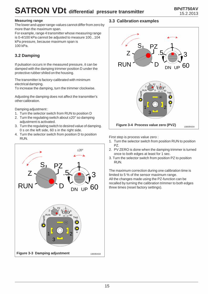
3.2 Damping
If pulsation occurs in the measured pressure, it can bedamped with the damping trimmer position D under theprotective rubber shiled on the housing.
Measuring rangeThe lower and upper range-values cannot differ from zero bymore than the maximum span.For example, range 4 transmitter whose measuring rangeis 0-4/100 kPa cannot be adjusted to measure 100...104kPa pressure, because maximum span is100 kPa.
The transmitter is factory-calibrated with minimumelectrical damping.To increase the damping, turn the trimmer clockwise.
Adjusting the damping does not affect the transmitter'sother calibration.
Damping adjustment :1. Turn the selector switch from RUN to position D2. Turn the regulating switch about ±20° so damping
adjustment is activated.3. Turn the regulating switch to desired value of damping.
0 s on the left side, 60 s in the right side.4. Turn the selector switch from position D to position
RUN.
Figure 3-4 Process value zero (PVZ)
3.3 Calibration examples
First step is process value zero :1. Turn the selector switch from position RUN to position
PZ.2. PV ZERO is done when the damping trimmer is turned
once to both edges at least for 1 sec.3. Turn the selector switch from position PZ to position
RUN.
The maximum correction during one calibration time islimited to 5 % of the sensor maximum range.All the changes made using the PZ-function can berecalled by turning the calibration trimmer to both edgesthree times (reset factory settings).
1300354154
Har
t® Test
321
13
60
.5
DN UP
PZ
DRUN
ZS
13
60
.5
DN UP
PZ
DRUN
ZS
15
Figure 3-3 Damping adjustment 1300354154
±20°
Har
t® Test
321
13
60
.5
DN UP
PZ
DRUN
ZS
13
60
.5
DN UP
PZ
DRUN
ZS
SATRON VDt differential pressure transmitter BPdT750AV15.2.2013
16
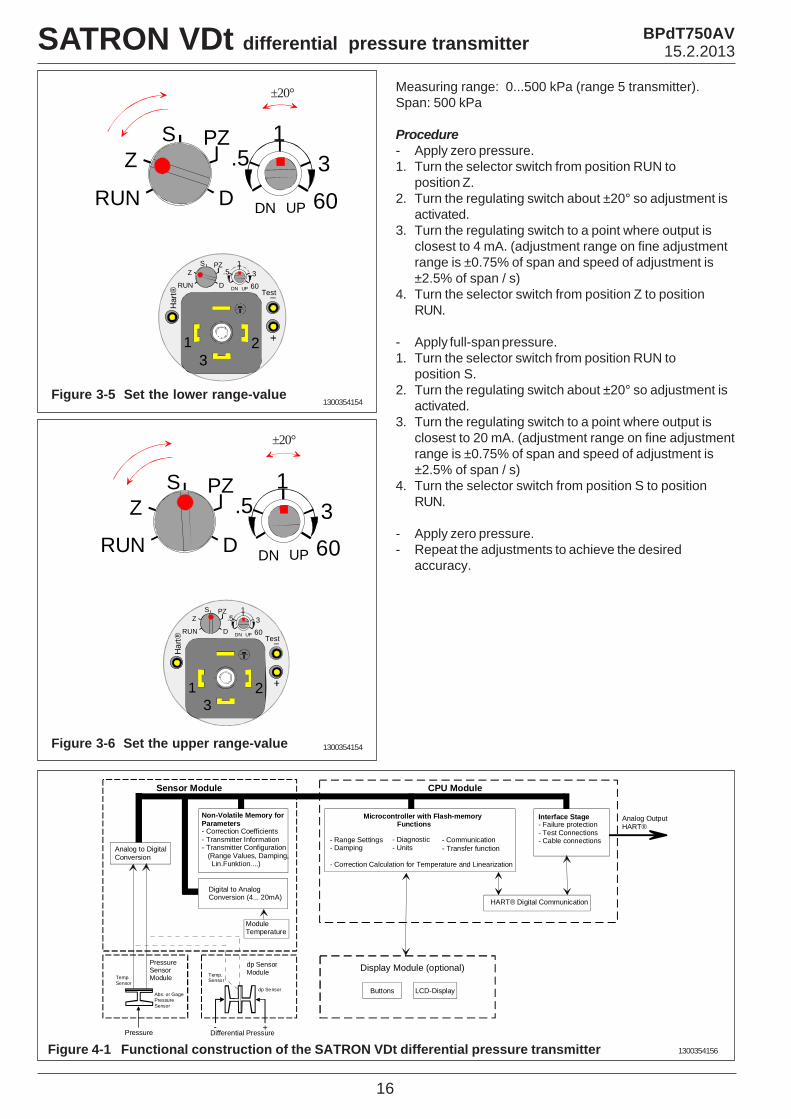
Measuring range: 0...500 kPa (range 5 transmitter).Span: 500 kPa
Procedure- Apply zero pressure.1. Turn the selector switch from position RUN to
position Z.2. Turn the regulating switch about ±20° so adjustment is
activated.3. Turn the regulating switch to a point where output is
closest to 4 mA. (adjustment range on fine adjustmentrange is ±0.75% of span and speed of adjustment is±2.5% of span / s)
4. Turn the selector switch from position Z to positionRUN.
- Apply full-span pressure.1. Turn the selector switch from position RUN to
position S.2. Turn the regulating switch about ±20° so adjustment is
activated.3. Turn the regulating switch to a point where output is
closest to 20 mA. (adjustment range on fine adjustmentrange is ±0.75% of span and speed of adjustment is±2.5% of span / s)
4. Turn the selector switch from position S to positionRUN.
- Apply zero pressure.- Repeat the adjustments to achieve the desired
accuracy.
Figure 3-5 Set the lower range-value1300354154
±20°
Har
t® Test
321
13
60
.5
DN UP
PZ
DRUN
ZS
13
60
.5
DN UP
PZ
DRUN
ZS
Figure 3-6 Set the upper range-value 1300354154
±20°
Har
t® Test
321
1360
.5
DN UP
PZ
DRUN
ZS
13
60
.5
DN UP
PZ
DRUN
ZS
Figure 4-1 Functional construction of the SATRON VDt differential pressure transmitter 1300354156
SATRON VDt differential pressure transmitter BPdT750AV15.2.2013
Sensor Module
Analog to DigitalConversion
Non-Volatile Memory forParameters- Correction Coefficients- Transmitter Information- Transmitter Configuration (Range Values, Damping, Lin.Funktion....)
CPU Module
Microcontroller with Flash-memory Functions
- Range Settings - Damping
- Correction Calculation for Temperature and Linearization
- Diagnostic- Units
- Communication
Buttons LCD-Display
Interface Stage- Failure protection- Test Connections- Cable connections
Pressure
Temp.Sensor
- Transfer function
Module Temperature
HART® Digital Communication
Analog OutputHART®
Digital to AnalogConversion (4... 20mA)
Display Module (optional)
Abs. or GagePressureSensor
PressureSensorModule Temp.
Sensor
dp Sensor
dp SensorModule
Differential Pressure - +
4. CONSTRUCTION ANDOPERATIONSensor ModuleThe piezoresistive sensor, which has a silicone oil fill, isisolated from the process with a diaphragm. Sensorpressure and temperature are measured with a 24-bit ADconverter. Linearity and temperature effects are digitallycorrected with an internal microprocessor connected to thesensor module.The sensor converts pressure to electrical signal. Theconversion is carried out through a Wheatstone bridgesupplied with direct current. The elastic displacementproduced in the bridge by the pressure causes bridgeunbalance which is measured as a DC voltage signal.
Compensation includes temperature compensation andlinearization. Each sensor is calibrated individuallythrough a resistance network connection. The temperatureinformation required by compensation is derived from atemperature measuring element located by theWheatstone bridge.
Electronics ModuleThe electronics module converts the process pressuresignal from the sensor module to 4-20 mA output signal.The conversion can be made in linear, square root orinverted mode, or it can be done through user-selectablepressure/output point pairs (2-16 points).
Transmitters provided with own display (code N) isequipped with operating keys that allow you to define thetransmitter’s all functions.The active functions required for signal shapingare in a customized IC which is divided into two sub-blocks: amplifier block and standard-signal shaping block.The standard-signal shaping block also includes zero,span and damping adjustments.
The interface stage includes failure protections toensure the transmitter's operation and nonfailure inpossible failure conditions. This stage also includes theTEST and cable connections
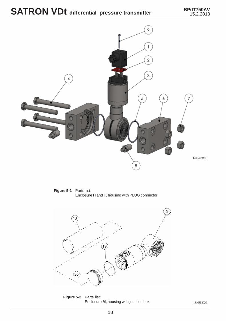
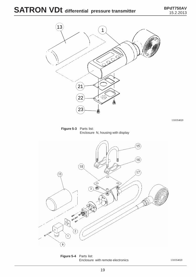
5. PARTS LISTWhen ordering spares, please quote this document’snumber BPdT750AV and date 15.2.2013, the name and
order number of the required part, and the transmitter’sserial number. Parts indicated with asterisk (*) as well asscrews, nuts and seals (packings) are spare parts.
17
SATRON VDt differential pressure transmitter
Name
Wiring box GDM3009,DIN43650Seal GDM3-17, siliconeSensing elementHex bolt, M10x90 DIN931 A4Hex bolt, M10x90 DIN9318.8 Zne (PN420)
Seal 46/50x1.7 PTFEFlange (PN420, M10)Flange (PN400, M12)
Hex nut, M10 SFS2067 A4Hex nut, M10 SFS2067m 8.8 Zne (PN420)Vent/drain valve, ¼-NPTCylinder-head screw S M3x35SFS2179 A4
Name
* 13
* 13
* 15* 16
17* 18
19* 20
21* 22
23
T1300295
T1300400
T544953T54322356022800T105000980013800T1300256T1300387T1300391T1325347
NumberNumber Order number
Protection cup, housing H, Mand TProtection cup, housing N
Mounting clampSupport plateHex nut M8 SFS2067 A4Mounting bracket SO-ring, 42x2 FPM (Viton®)Cover MSeal, Silicone rubberBack plate VFastening screw, M4
* 1
234
5* 6
7
* 89
Order number
72900111
72900116
54228190
54228191
T1310219T1310217T1310217-M12
56022810
56022817
T53187351723053
BPdT750AV15.2.2013
18
Figure 5-1 Parts list:Enclosure H and T, housing with PLUG connector
Figure 5-2 Parts list:Enclosure M, housing with junction box
SATRON VDt differential pressure transmitter BPdT750AV15.2.2013
1310354020
1310354020
19
Figure 5-4 Parts list:Enclosure with remote electronics
Figure 5-3 Parts list:Enclosure N, housing with display
SATRON VDt differential pressure transmitter BPdT750AV15.2.2013
1310354020
1310354020
21
22
1
23
13

20
SATRON VDt differential pressure transmitter BPdT750AV15.2.2013
Satron Instruments Inc.P.O.Box 22, FIN-33901 Tampere, Finland
Tel.int. +358 207 464 800, Telefax +358 207 464 801www.satron.com, [email protected]
Conmark Systems Inc. Instruments Div. Atlanta, GA 770-300-0224www.conmark.com