Embed Size (px)
Citation preview

NSW (Head Office)7 Columbia CourtNorwest Business ParkBaulkham Hills NSW 2153
Ph: (02) 9899-4155Fax: (02) 9899-4156
QLD16 Lucy StMoorookaQld 4104
Ph: (07) 3892-6444Fax: (07) 3892-6455
VICUnit 2 297 Ingles StPort MelbourneVic 3207
Ph: (03) 9681-9929Fax: (03) 9681-9930
Notifier Inertia Pty Ltd (A.C.N 002 692 962)
A PITTWAY COMPANYA PITTWAY COMPANYwww.inertia.com.au
INSTALLATION AND PROGRAMMING MANUAL
AFP-300/400
INTELLIGENT FIREDETECTION ANDALARM SYSTEM
SOFTWARE VERSION 2.2REVISION AUS 3
Technical Manuals Online! - http://www.tech-man.com
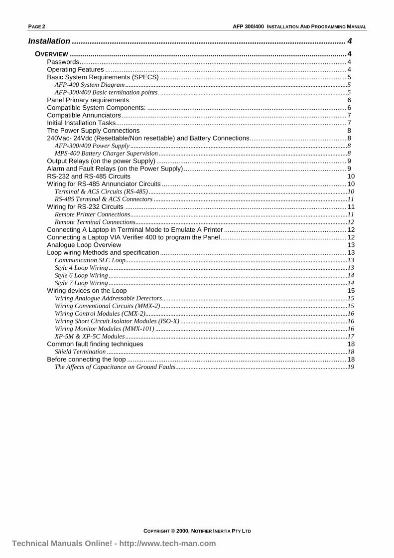
PAGE 2 AFP 300/400 INSTALLATION AND PROGRAMMING MANUAL
COPYRIGHT © 2000, NOTIFIER INERTIA PTY LTD
Installation ........................................................................................................................... 4
OVERVIEW ......................................................................................................................................4Passwords.................................................................................................................................................. 4Operating Features .................................................................................................................................... 4Basic System Requirements (SPECS) ...................................................................................................... 5
AFP-400 System Diagram.....................................................................................................................................5AFP-300/400 Basic termination points. ................................................................................................................5
Panel Primary requirements 6Compatible System Components: ............................................................................................................. 6Compatible Annunciators........................................................................................................................... 7Initial Installation Tasks.............................................................................................................................. 7The Power Supply Connections 8240Vac- 24Vdc (Resettable/Non resettable) and Battery Connections..................................................... 8
AFP-300/400 Power Supply ..................................................................................................................................8MPS-400 Battery Charger Supervision .................................................................................................................8
Output Relays (on the power Supply) ........................................................................................................ 9Alarm and Fault Relays (on the Power Supply) ......................................................................................... 9RS-232 and RS-485 Circuits 10Wiring for RS-485 Annunciator Circuits ..................................................................................................... 10
Terminal & ACS Circuits (RS-485) .......................................................................................................................10RS-485 Terminal & ACS Connectors ....................................................................................................................11
Wiring for RS-232 Circuits ......................................................................................................................... 11Remote Printer Connections..................................................................................................................................11Remote Terminal Connections...............................................................................................................................12
Connecting A Laptop in Terminal Mode to Emulate A Printer ................................................................... 12Connecting a Laptop VIA Verifier 400 to program the Panel..................................................................... 12Analogue Loop Overview 13Loop wiring Methods and specification ...................................................................................................... 13
Communication SLC Loop.....................................................................................................................................13Style 4 Loop Wiring ...............................................................................................................................................13Style 6 Loop Wiring ...............................................................................................................................................14Style 7 Loop Wiring ...............................................................................................................................................14
Wiring devices on the Loop 15Wiring Analogue Addressable Detectors...............................................................................................................15Wiring Conventional Circuits (MMX-2)................................................................................................................15Wiring Control Modules (CMX-2).........................................................................................................................16Wiring Short Circuit Isolator Modules (ISO-X) ....................................................................................................16Wiring Monitor Modules (MMX-101) ...................................................................................................................16XP-5M & XP-5C Modules .....................................................................................................................................17
Common fault finding techniques 18Shield Termination ................................................................................................................................................18
Before connecting the loop ........................................................................................................................ 18The Affects of Capacitance on Ground Faults.......................................................................................................19
Technical Manuals Online! - http://www.tech-man.com
AFP 300/400 INSTALLATION AND PROGRAMMING MANUAL PAGE 3
COPYRIGHT © 2000, NOTIFIER INERTIA PTY LTD
Programming....................................................................................................................... 20
OVERVIEW ......................................................................................................................................20Turning the Panel on for the first Time 20How to enter a ‘Default’ Program............................................................................................................... 20Program Mode Screen............................................................................................................................... 21Clear Program............................................................................................................................................ 21Autoprogram .............................................................................................................................................. 21
Duplicate (Dual) Addressing.................................................................................................................................22Default Autoprogram Screen.................................................................................................................................23Autoprogram Defaults ...........................................................................................................................................23
Autoprogram- Device no longer needed.................................................................................................... 24Installing a Device ...................................................................................................................................... 24Edit a Point................................................................................................................................................. 24Modifying a Point........................................................................................................................................ 24Editing Multi Detector Mode....................................................................................................................... 25
Programming Cooperative Multi-Detector ...........................................................................................................25Delete a Point............................................................................................................................................. 26Password ................................................................................................................................................... 26Message - Change the “SYSTEM NORMAL MESSAGE” ......................................................................... 26Zone Labels ............................................................................................................................................... 27Special Zones ............................................................................................................................................ 27
F5-F6 (TIME CONTROL) .....................................................................................................................................28F7 (Holiday) ..........................................................................................................................................................28
System Functions 29Annunciator selection 30Annunciator Groups ................................................................................................................................... 30
Annunciator Group 1.............................................................................................................................................30Annunciator Group 2.............................................................................................................................................31Annunciator Group 3-5 .........................................................................................................................................31Annunciator Group 6 – 8.......................................................................................................................................31
System Check Function ............................................................................................................................. 32Status Change 32Isolate a Device or Zone ............................................................................................................................ 33Change Sensitivity ..................................................................................................................................... 33Clear Verification Counters ........................................................................................................................ 33Clear History .............................................................................................................................................. 34Time and Date............................................................................................................................................ 34Walk Test ................................................................................................................................................... 34Type Codes (ID’s) 35Monitor Module’s........................................................................................................................................ 35
Type Codes for Monitor Modules ..........................................................................................................................35Control Module’s ........................................................................................................................................ 36
Type Codes for Control Modules...........................................................................................................................36Panel’s Monitored Output Circuits ............................................................................................................. 36Control-By-Event Programming 37
CBE Equation........................................................................................................................................................37Automatically Change sensitivity ..........................................................................................................................37
Nominal Detector Sensitivity 38Self Optimising Pre-Alarm ....................................................................................................................................38
Sensitivity Levels for the AFP-400: (Graph)............................................................................................... 39Sensitivity Levels- Autoprogram Default Tables: ..................................................................................................40
Technical Manuals Online! - http://www.tech-man.com

PAGE 4 AFP 300/400 INSTALLATION AND PROGRAMMING MANUAL
COPYRIGHT © 2000, NOTIFIER INERTIA PTY LTD
InstallationOverviewThe AFP-400 is a modular, intelligent Fire Alarm Control Panel (FACP) with an extensive list ofpowerful features. The CPU module, power supply module, and cabinet combine to create acomplete fire control system for most applications such as commercial, residential and industrialbuildings. Optional modules mount to the chassis to provide additional output circuits.
Unlike conventional fire control panels, the AFP-300/400 intelligently communicates with eachdetector and Input/Output module on the entire system. Thus providing accurate information asto the exact point of alarm and the ability to operate specific outputs using programmable logicfunctions. The method of communication with field devices is a high-speed proprietary protocolcapable of supporting up to 99 detectors and 99 modules per two-wire loop.
The AFP-300 panel is capable of 1 loop and the AFP-400 is capable of 2 loops. Each of thepanels can also accommodate up to 10 Annunciators, each can provide 32 x fullyprogrammable LED indications, 16 x single pushbutton functions, 8 x relay outputs, remote LCDdisplays etc.
These systems due to their immense flexibility require a firm understanding of the totaloperation of the system for their correct operation. Please ensure that the following document isread in its entirety before making any attempt to operate the system.
Passwords
As the program in the system is critical to the correct operation during fire alarm conditions, it isprotected from modification by a five-digit password. All other features are available withoutpassword protection.Please ensure the password is recorded and stored in a safe place as it remains unique andyour key to future system modification.
Operating FeaturesAlarm Verification selection per point, with tally.Silence Inhibit timer and Auto Silence timer.Automatic time-of-day and day-of-week controls functions, with holiday option.User-defined password and key-protected nonvolatile memory.AWACS (Advanced Warning Addressable Combustion Sensing) with nine field-adjustable Pre-Alarm levels with programmable Control-by-Event (CBE)Operate automatic smoke or heat detector sounder base on action Pre-Alarm level, with generalevacuation on alarm level.Programmable Control-by-Event control of outputs from individual alarm addressable devices.
Technical Manuals Online! - http://www.tech-man.com
AFP 300/400 INSTALLATION AND PROGRAMMING MANUAL PAGE 5
COPYRIGHT © 2000, NOTIFIER INERTIA PTY LTD
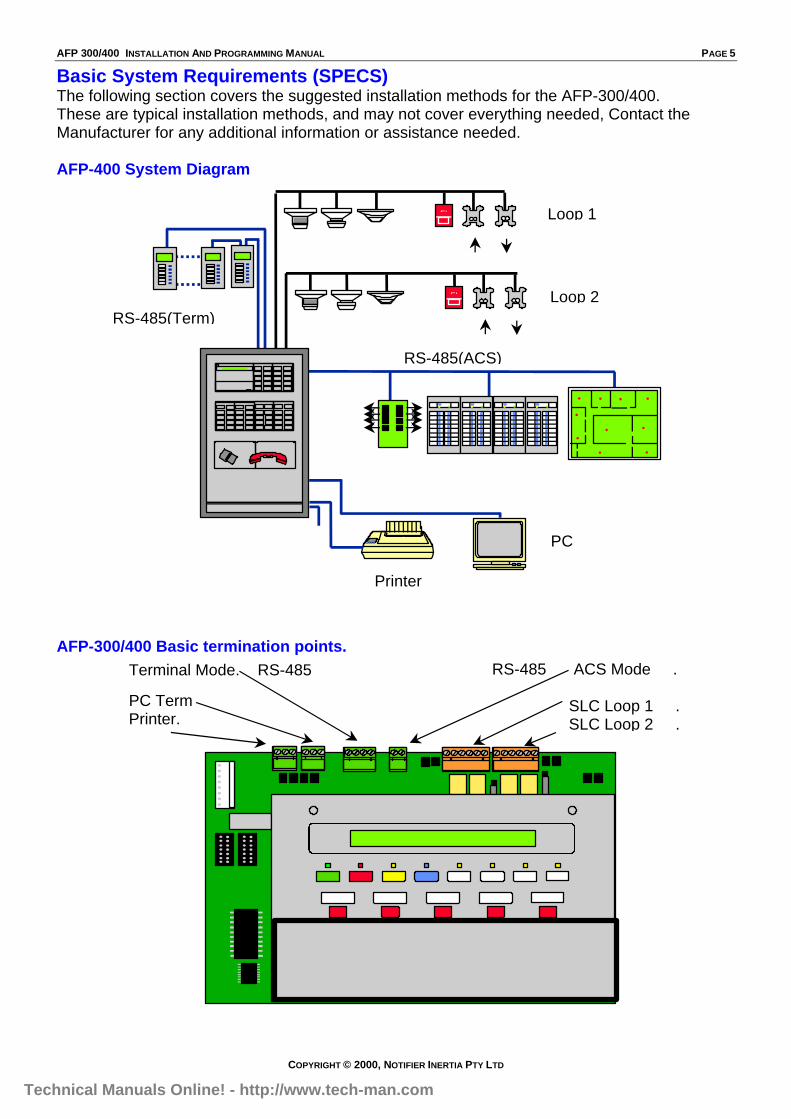
Terminal Mode. RS-485
PC Term Printer.
RS-485 ACS Mode .
SLC Loop 1 .SLC Loop 2 .
Basic System Requirements (SPECS)The following section covers the suggested installation methods for the AFP-300/400.These are typical installation methods, and may not cover everything needed, Contact theManufacturer for any additional information or assistance needed.
AFP-400 System Diagram
AFP-300/400 Basic termination points.
NCSGraphicsOptional
Printer
PC
RS-485(Term)
Loop 1
Loop 2FI
FI
RS-485(ACS)
Technical Manuals Online! - http://www.tech-man.com
PAGE 6 AFP 300/400 INSTALLATION AND PROGRAMMING MANUAL
COPYRIGHT © 2000, NOTIFIER INERTIA PTY LTD
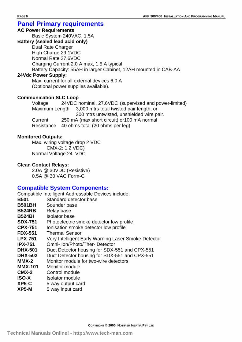
Panel Primary requirementsAC Power Requirements
Basic System 240VAC, 1.5ABattery (sealed lead acid only)
Dual Rate ChargerHigh Charge 29.1VDCNormal Rate 27.6VDCCharging Current 2.0 A max, 1.5 A typicalBattery Capacity: 55AH in larger Cabinet, 12AH mounted in CAB-AA
24Vdc Power Supply:Max. current for all external devices 6.0 A(Optional power supplies available).
Communication SLC LoopVoltage 24VDC nominal, 27.6VDC (supervised and power-limited)Maximum Length 3,000 mtrs total twisted pair length, or
300 mtrs untwisted, unshielded wire pair.Current 250 mA (max short circuit) or100 mA normalResistance 40 ohms total (20 ohms per leg)
Monitored Outputs:Max. wiring voltage drop 2 VDC
CMX-2: 1.2 VDC)Normal Voltage 24 VDC
Clean Contact Relays:2.0A @ 30VDC (Resistive)0.5A @ 30 VAC Form-C
Compatible System Components:Compatible Intelligent Addressable Devices include;B501 Standard detector baseB501BH Sounder baseB524RB Relay baseB524BI Isolator baseSDX-751 Photoelectric smoke detector low profileCPX-751 Ionisation smoke detector low profileFDX-551 Thermal SensorLPX-751 Very Intelligent Early Warning Laser Smoke DetectorIPX-751 Omni- Ion/Photo/Ther- DetectorDHX-501 Duct Detector housing for SDX-551 and CPX-551DHX-502 Duct Detector housing for SDX-551 and CPX-551MMX-2 Monitor module for two-wire detectorsMMX-101 Monitor moduleCMX-2 Control moduleISO-X Isolator moduleXP5-C 5 way output cardXP5-M 5 way input card
Technical Manuals Online! - http://www.tech-man.com

AFP 300/400 INSTALLATION AND PROGRAMMING MANUAL PAGE 7
COPYRIGHT © 2000, NOTIFIER INERTIA PTY LTD
Compatible AnnunciatorsACM-16AT - Contains 16 red alarm and 16 yellow LEDs, and a local piezo sounder,
Includes 16 switches for control panel functions.AEM-16AT - Expands the ACM-16AT by 16 system points per unit, up to a maximum of 64
points per address.ACM-32A - Contains 32 red alarm LEDs, and a local piezo sounder with silence/acknowledge
switch.AEM-32A - Expands the ACM-32A by 32 pointsACM-8R- Provides eight Clean contact (Form-C) relays with 5A contactsLDM-32- Provides 32 Led driver outputs for connection to a custom graphic Mimic.
Programmable for 32 alarm only outputs, or 16 alarm and 16 fault outputs.LDM-E32- Expands the LDM-32 by 32 points up to a maximum of 64 points.LDM-R32- Converts the open collector outputs of an LDM-32 or LDM-E32 to Form-A
(normally open) contacts.LCD-80- Alphanumeric display Mimic Panel
Initial Installation TasksCheck AC Power –
Apply AC power to the MPS-400, but do not connect batteries at this time.Silence the audible fault sounder by pushing the Acknowledge switch on the Keypad.
The Panel should indicate:The Green AC power LED onSystem Fault indicator because of no batteriesThe yellow fault indicator may come on after 10 seconds.
Program the AFP-400 (See Programming)Connect the BatteriesCarry out common fault finding techniques (Page 19)Test the System.
Technical Manuals Online! - http://www.tech-man.com
PAGE 8 AFP 300/400 INSTALLATION AND PROGRAMMING MANUAL
COPYRIGHT © 2000, NOTIFIER INERTIA PTY LTD
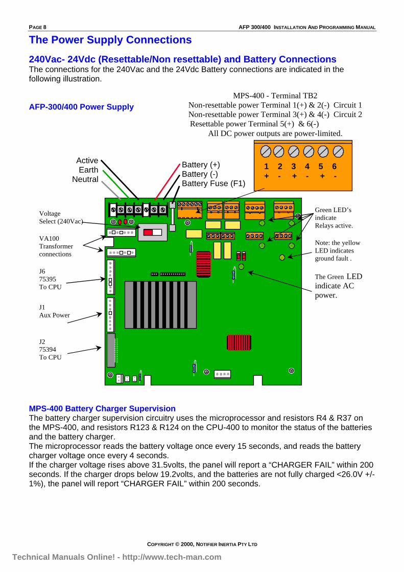
The Power Supply Connections
240Vac- 24Vdc (Resettable/Non resettable) and Battery ConnectionsThe connections for the 240Vac and the 24Vdc Battery connections are indicated in thefollowing illustration.
AFP-300/400 Power Supply
MPS-400 Battery Charger SupervisionThe battery charger supervision circuitry uses the microprocessor and resistors R4 & R37 onthe MPS-400, and resistors R123 & R124 on the CPU-400 to monitor the status of the batteriesand the battery charger.The microprocessor reads the battery voltage once every 15 seconds, and reads the batterycharger voltage once every 4 seconds.If the charger voltage rises above 31.5volts, the panel will report a “CHARGER FAIL” within 200seconds. If the charger drops below 19.2volts, and the batteries are not fully charged <26.0V +/-1%), the panel will report “CHARGER FAIL” within 200 seconds.
MPS-400 - Terminal TB2Non-resettable power Terminal 1(+) & 2(-) Circuit 1Non-resettable power Terminal 3(+) & 4(-) Circuit 2
Resettable power Terminal 5(+) & 6(-)All DC power outputs are power-limited.
VoltageSelect (240Vac)
VA100Transformerconnections
J675395To CPU
J1Aux Power
J275394To CPU
Green LED’sindicateRelays active.
Note: the yellowLED indicatesground fault .
The Green LEDindicate ACpower.
BBEA HN
ActiveEarth
Neutral
Battery (+)Battery (-)Battery Fuse (F1)
1 2 3 4 5 6+ - + - + -
Technical Manuals Online! - http://www.tech-man.com
AFP 300/400 INSTALLATION AND PROGRAMMING MANUAL PAGE 9
COPYRIGHT © 2000, NOTIFIER INERTIA PTY LTD
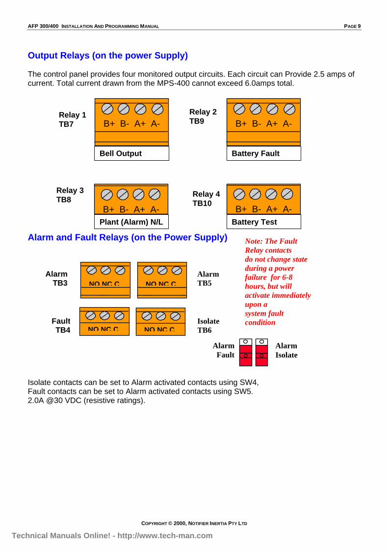
Output Relays (on the power Supply)
The control panel provides four monitored output circuits. Each circuit can Provide 2.5 amps ofcurrent. Total current drawn from the MPS-400 cannot exceed 6.0amps total.
Alarm and Fault Relays (on the Power Supply)
Isolate contacts can be set to Alarm activated contacts using SW4,Fault contacts can be set to Alarm activated contacts using SW5.2.0A @30 VDC (resistive ratings).
NO NC C NO NC C
NO NC C NO NC C
AlarmTB3
AlarmTB5
FaultTB4
IsolateTB6
AlarmFault
AlarmIsolate
Note: The FaultRelay contactsdo not change stateduring a powerfailure for 6-8hours, but willactivate immediatelyupon asystem faultcondition
Relay 1TB7 B+ B- A+ A-B+ B- A+ A-
B+ B- A+ A-B+ B- A+ A-
Relay 2TB9
Relay 3TB8
Relay 4TB10
Battery FaultBell Output
Plant (Alarm) N/L Battery Test
Technical Manuals Online! - http://www.tech-man.com
PAGE 10 AFP 300/400 INSTALLATION AND PROGRAMMING MANUAL
COPYRIGHT © 2000, NOTIFIER INERTIA PTY LTD
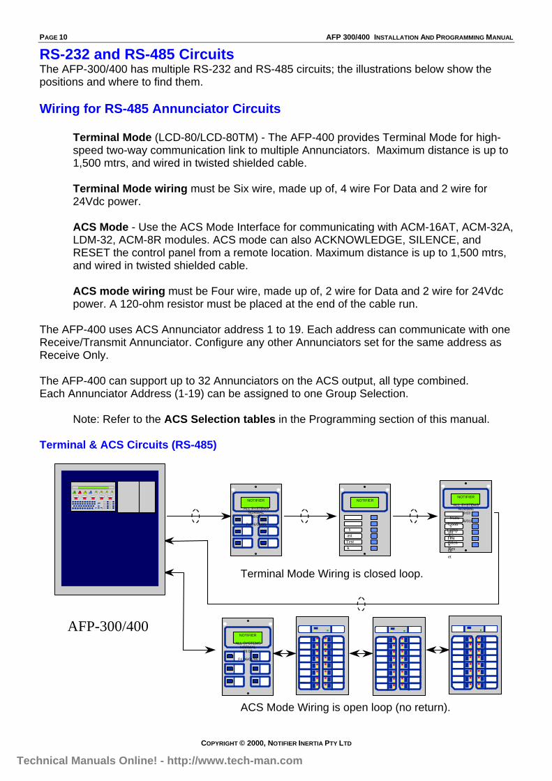
RS-232 and RS-485 CircuitsThe AFP-300/400 has multiple RS-232 and RS-485 circuits; the illustrations below show thepositions and where to find them.
Wiring for RS-485 Annunciator Circuits
Terminal Mode (LCD-80/LCD-80TM) - The AFP-400 provides Terminal Mode for high-speed two-way communication link to multiple Annunciators. Maximum distance is up to1,500 mtrs, and wired in twisted shielded cable.
Terminal Mode wiring must be Six wire, made up of, 4 wire For Data and 2 wire for24Vdc power.
ACS Mode - Use the ACS Mode Interface for communicating with ACM-16AT, ACM-32A,LDM-32, ACM-8R modules. ACS mode can also ACKNOWLEDGE, SILENCE, andRESET the control panel from a remote location. Maximum distance is up to 1,500 mtrs,and wired in twisted shielded cable.
ACS mode wiring must be Four wire, made up of, 2 wire for Data and 2 wire for 24Vdcpower. A 120-ohm resistor must be placed at the end of the cable run.
The AFP-400 uses ACS Annunciator address 1 to 19. Each address can communicate with oneReceive/Transmit Annunciator. Configure any other Annunciators set for the same address asReceive Only.
The AFP-400 can support up to 32 Annunciators on the ACS output, all type combined.Each Annunciator Address (1-19) can be assigned to one Group Selection.
Note: Refer to the ACS Selection tables in the Programming section of this manual.
Terminal & ACS Circuits (RS-485)
AFP-300/400
NOTIFIER
ALL SYSTEMSNORMAL
09:03
Fri 06/01/95Statu
sContr
astLamp
TestAc
kSilen
ceRes
et
NOTIFIER
sastTestk
NOTIFIER
ALL SYSTEMSNORMAL
09:03
Fri 06/01/95
NOTIFIER
ALL SYSTEMSNORMAL
09:03
Fri 06/01/95
Terminal Mode Wiring is closed loop.
ACS Mode Wiring is open loop (no return).
Technical Manuals Online! - http://www.tech-man.com

AFP 300/400 INSTALLATION AND PROGRAMMING MANUAL PAGE 11
COPYRIGHT © 2000, NOTIFIER INERTIA PTY LTD
RS-485 Terminal & ACS Connectors
AFP400 to LCD-80 Terminal Mode ConnectionsAFP 400 End (TB3 Terminal Mode Output) LCD-80(TM) End (TB2)RS 485 IN + RS 485 OUT + (Terminal 1)RS 485 IN - RS 485 OUT – (Terminal 3)RS 485 OUT + RS 485 IN + (Terminal 2)RS 485 OUT - RS 485 IN – (Terminal 4)
Wiring for RS-232 CircuitsRS-232 circuits used for printer’s etc, wired outside of the Panel, are to be wired in TwistedShielded wiring and not to exceed 15 mtrs in length. The shield must be earthed at the Panelend, to the nearest earth point immediately inside the Panel.
The following illustrations indicate the connection points for RS-232 circuits.
Remote Printer Connections
TX RX REFPRINTER
TX RX REFPC/TERMINAL
TB1 TB2 TB3
RS485 RS485TERM IN TERM OUT
PRN DB-9 PRN DB-25 AFP400(TB1)TX (Pin 2) TX (Pin 3) TB1-1RX (Pin 3) RX (Pin 2) TB1-2REF (Pin 5) REF (Pin 7) TB1-3
DB-25 connector
+ -
EIA-
Return + -
Output+ - + -
LCD-80 Terminal ModeConnections ACS EIA-485 Connections
Technical Manuals Online! - http://www.tech-man.com
PAGE 12 AFP 300/400 INSTALLATION AND PROGRAMMING MANUAL
COPYRIGHT © 2000, NOTIFIER INERTIA PTY LTD
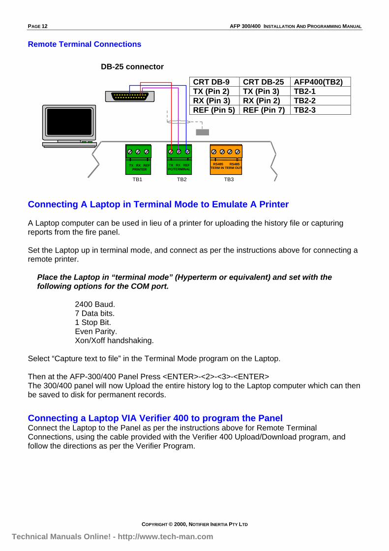
Remote Terminal Connections
Connecting A Laptop in Terminal Mode to Emulate A Printer
A Laptop computer can be used in lieu of a printer for uploading the history file or capturingreports from the fire panel.
Set the Laptop up in terminal mode, and connect as per the instructions above for connecting aremote printer.
Place the Laptop in “terminal mode” (Hyperterm or equivalent) and set with thefollowing options for the COM port.
2400 Baud.7 Data bits.1 Stop Bit.Even Parity.Xon/Xoff handshaking.
Select “Capture text to file” in the Terminal Mode program on the Laptop.
Then at the AFP-300/400 Panel Press <ENTER>-<2>-<3>-<ENTER>The 300/400 panel will now Upload the entire history log to the Laptop computer which can thenbe saved to disk for permanent records.
Connecting a Laptop VIA Verifier 400 to program the PanelConnect the Laptop to the Panel as per the instructions above for Remote TerminalConnections, using the cable provided with the Verifier 400 Upload/Download program, andfollow the directions as per the Verifier Program.
TX RX REFPRINTER
TX RX REFPC/TERMINAL
TB1 TB2 TB3
RS485 RS485TERM IN TERM OUT
CRT DB-9 CRT DB-25 AFP400(TB2)TX (Pin 2) TX (Pin 3) TB2-1RX (Pin 3) RX (Pin 2) TB2-2REF (Pin 5) REF (Pin 7) TB2-3
DB-25 connector
Technical Manuals Online! - http://www.tech-man.com
AFP 300/400 INSTALLATION AND PROGRAMMING MANUAL PAGE 13
COPYRIGHT © 2000, NOTIFIER INERTIA PTY LTD
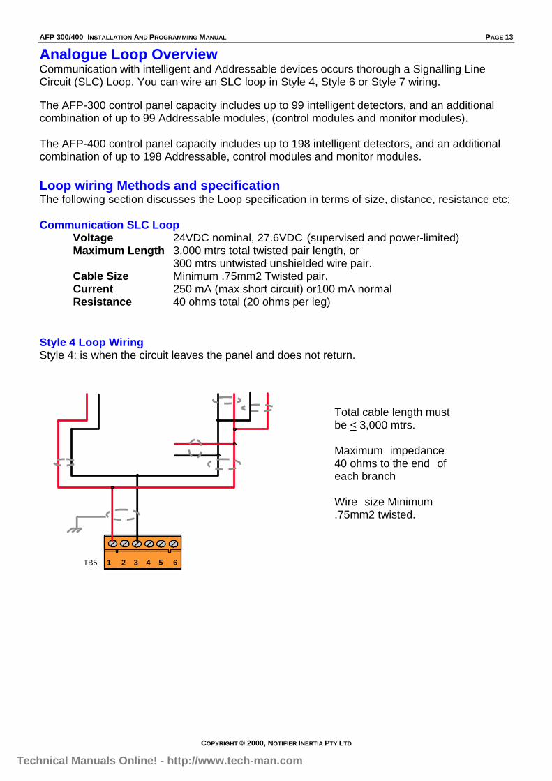
Analogue Loop OverviewCommunication with intelligent and Addressable devices occurs thorough a Signalling LineCircuit (SLC) Loop. You can wire an SLC loop in Style 4, Style 6 or Style 7 wiring.
The AFP-300 control panel capacity includes up to 99 intelligent detectors, and an additionalcombination of up to 99 Addressable modules, (control modules and monitor modules).
The AFP-400 control panel capacity includes up to 198 intelligent detectors, and an additionalcombination of up to 198 Addressable, control modules and monitor modules.
Loop wiring Methods and specificationThe following section discusses the Loop specification in terms of size, distance, resistance etc;
Communication SLC LoopVoltage 24VDC nominal, 27.6VDC (supervised and power-limited)Maximum Length 3,000 mtrs total twisted pair length, or
300 mtrs untwisted unshielded wire pair.Cable Size Minimum .75mm2 Twisted pair.Current 250 mA (max short circuit) or100 mA normalResistance 40 ohms total (20 ohms per leg)
Style 4 Loop WiringStyle 4: is when the circuit leaves the panel and does not return.
1 2 3 4 5 6TB5
Total cable length mustbe < 3,000 mtrs.
Maximum impedance40 ohms to the end ofeach branch
Wire size Minimum.75mm2 twisted.
Technical Manuals Online! - http://www.tech-man.com
PAGE 14 AFP 300/400 INSTALLATION AND PROGRAMMING MANUAL
COPYRIGHT © 2000, NOTIFIER INERTIA PTY LTD
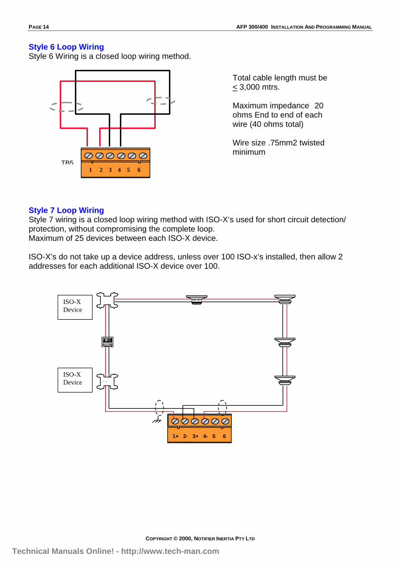
Style 6 Loop WiringStyle 6 Wiring is a closed loop wiring method.
Style 7 Loop WiringStyle 7 wiring is a closed loop wiring method with ISO-X‘s used for short circuit detection/protection, without compromising the complete loop.Maximum of 25 devices between each ISO-X device.
ISO-X’s do not take up a device address, unless over 100 ISO-x’s installed, then allow 2addresses for each additional ISO-X device over 100.
1+ 2- 3+ 4- 5 6
IS
IS
Total cable length must be< 3,000 mtrs.
Maximum impedance 20ohms End to end of eachwire (40 ohms total)
Wire size .75mm2 twistedminimum
TB51 2 3 4 5 6
ISO-XDevice
ISO-XDevice
Technical Manuals Online! - http://www.tech-man.com

AFP 300/400 INSTALLATION AND PROGRAMMING MANUAL PAGE 15
COPYRIGHT © 2000, NOTIFIER INERTIA PTY LTD
Wiring devices on the Loop
Please Note; Some of the wiring methods used in this manual only apply to the AFP-300/400,do not adopt these methods on other systems.
Wiring Analogue Addressable Detectors
Note:If optional shield used, do not connect to the spare terminal on the detector base, join the shieldand insulate it from the other cables.
Wiring Conventional Circuits (MMX-2)The MMX-2 utilises the 24Vdc Resettable power supply, and the Conventional circuit isterminated to terminal 6 & 7, with a 3.9k EOL Resistor fitted.
Note:You must use resettable power on MMX-2’s on an AFP400.You cannot have AVF on an MMX-2 Module.
Technical Manuals Online! - http://www.tech-man.com
PAGE 16 AFP 300/400 INSTALLATION AND PROGRAMMING MANUAL
COPYRIGHT © 2000, NOTIFIER INERTIA PTY LTD
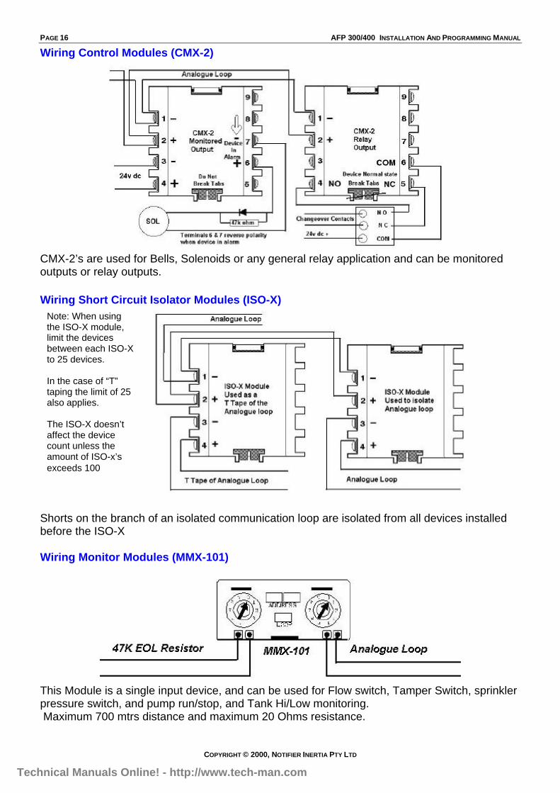
Wiring Control Modules (CMX-2)
CMX-2’s are used for Bells, Solenoids or any general relay application and can be monitoredoutputs or relay outputs.
Wiring Short Circuit Isolator Modules (ISO-X)
Shorts on the branch of an isolated communication loop are isolated from all devices installedbefore the ISO-X
Wiring Monitor Modules (MMX-101)
This Module is a single input device, and can be used for Flow switch, Tamper Switch, sprinklerpressure switch, and pump run/stop, and Tank Hi/Low monitoring. Maximum 700 mtrs distance and maximum 20 Ohms resistance.
Note: When usingthe ISO-X module,limit the devicesbetween each ISO-Xto 25 devices.
In the case of “T”taping the limit of 25also applies.
The ISO-X doesn’taffect the devicecount unless theamount of ISO-x’sexceeds 100
Technical Manuals Online! - http://www.tech-man.com
AFP 300/400 INSTALLATION AND PROGRAMMING MANUAL PAGE 17
COPYRIGHT © 2000, NOTIFIER INERTIA PTY LTD
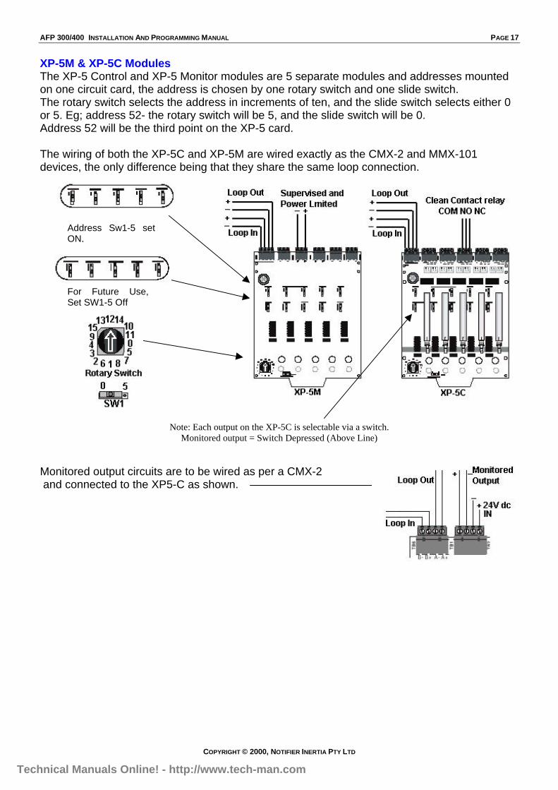
XP-5M & XP-5C ModulesThe XP-5 Control and XP-5 Monitor modules are 5 separate modules and addresses mountedon one circuit card, the address is chosen by one rotary switch and one slide switch.The rotary switch selects the address in increments of ten, and the slide switch selects either 0or 5. Eg; address 52- the rotary switch will be 5, and the slide switch will be 0.Address 52 will be the third point on the XP-5 card.
The wiring of both the XP-5C and XP-5M are wired exactly as the CMX-2 and MMX-101devices, the only difference being that they share the same loop connection.
Note: Each output on the XP-5C is selectable via a switch.Monitored output = Switch Depressed (Above Line)
Monitored output circuits are to be wired as per a CMX-2 and connected to the XP5-C as shown.
Address Sw1-5 setON,
For Future Use,Set SW1-5 Off
Technical Manuals Online! - http://www.tech-man.com

PAGE 18 AFP 300/400 INSTALLATION AND PROGRAMMING MANUAL
COPYRIGHT © 2000, NOTIFIER INERTIA PTY LTD
Common fault finding techniques
For a Loop that is wired in Twisted Shielded Pair:
Shield Termination
If Using optional shielded twisted pair cable to minimise radiated emissions of radiofrequency energy, do not allow the shield drain wire to enter the cabinet. Connect the drainwire to the outside of the cabinet via an earth type connector. Maintain the continuity of theshield wire throughout the loop but do not connect to any devices, do not allow the shield tobecome grounded and only earth one end.
Before connecting the loopCarry out the following tests;
1. Check continuity of loop wiring, by placing a short on one end and reading the short with amultimeter at the other end.
2. Check the loop resistance, same as above (be sure to set the multimeter to ohms), the loopresistance cannot exceed 40 ohms, which is 20 ohms per leg.
3. Check for devices incorrectly wired, set the multimeter to diode Test, and place the leads onthe cable, the reading should be approx .645,- reverse the leads- now the reading should beapprox 1.2 or higher, if both readings read low- this indicates a device incorrectly wired, or ashort on the wiring.
Note: (Each device has a diode installed)
4. Voltage reading, set the multimeter to D.C. volts and read the voltage at the loop card beforeconnecting the loop, the reading should be approx. 24 volts, now connect the loop, thereading should now be 15-16 volts. If the voltage goes down low this could indicate a shorton the line, or there is a device incorrectly wired (possible Reverse polarity), find the deviceand correct the loop connections at that device.
5. Earth Fault test, Select ohms on the multimeter and check between each leg of the loop andearth, if the reading falls below 50,000 ohms, an earth fault will appear on the loop whenconnected, find the cause of the earth fault and rectify. (Possible causes of an earth fault aremoisture, inadequate insulation from surrounding building, equipment or materials).
NOTE:Loop Resistance Measurement when ISO-X devices are present and when power is removedfrom the Loop, the positive side of the circuit is opened at each ISO-X isolation module. Tomeasure the Loop resistance, temporarily place a jumper between Terminals 2 and 4 oneach ISO-X while taking measurements. Remember to remove all the jumpers and test allisolator modules when you have finished taking the readings.
Loop+
Loop -
Connect to EnclosurePrior to connection,check withVOM for externalgrounds.
Technical Manuals Online! - http://www.tech-man.com

AFP 300/400 INSTALLATION AND PROGRAMMING MANUAL PAGE 19
COPYRIGHT © 2000, NOTIFIER INERTIA PTY LTD
The Affects of Capacitance on Ground FaultsCapacitance can be a major cause of induced ground faults. If the capacitance between theconductors and earth ground exceed a certain value, the capacitive reactance (Xc) will fallbelow the ground fault circuit threshold, and a ground fault condition will occur. When usingshielded cable for the SLC loop wiring, it is important to realise that since a conductor is runningin close proximity to the shield for a long distance, it is basically a large capacitor. If thecapacitive value is known, the capacitive reactance can be calculated by using this formula:
Xc = 1 2”fCWhere “F” is the frequency 0.5Hz, and “C” is the measured capacitive value in Microfarads. Ifthe capacitive reactance is below 50,000 ohms, a ground fault will result.
Technical Manuals Online! - http://www.tech-man.com
PAGE 20 AFP 300/400 INSTALLATION AND PROGRAMMING MANUAL
COPYRIGHT © 2000, NOTIFIER INERTIA PTY LTD
Programming
OverviewThe AFP-300/400 is 100% field programmable, and has the added versatility of theAutoprogram feature, the Panel can also be programmed using a Laptop Computer.
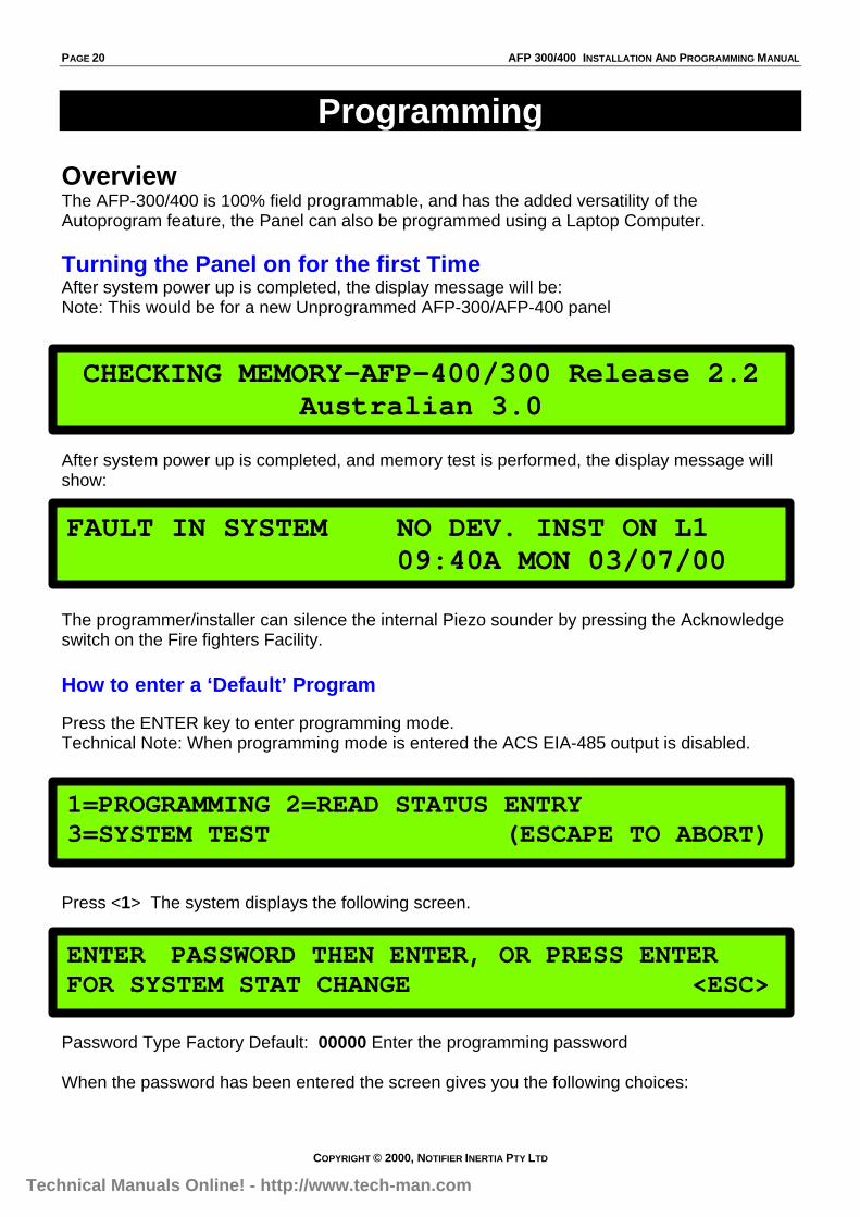
Turning the Panel on for the first TimeAfter system power up is completed, the display message will be:Note: This would be for a new Unprogrammed AFP-300/AFP-400 panel
After system power up is completed, and memory test is performed, the display message willshow:
The programmer/installer can silence the internal Piezo sounder by pressing the Acknowledgeswitch on the Fire fighters Facility.
How to enter a ‘Default’ Program
Press the ENTER key to enter programming mode.Technical Note: When programming mode is entered the ACS EIA-485 output is disabled.
Press <1> The system displays the following screen.
Password Type Factory Default: 00000 Enter the programming password
When the password has been entered the screen gives you the following choices:
CHECKING MEMORY-AFP-400/300 Release 2.2Australian 3.0
FAULT IN SYSTEM NO DEV. INST ON L1 09:40A MON 03/07/00
1=PROGRAMMING 2=READ STATUS ENTRY3=SYSTEM TEST (ESCAPE TO ABORT)
ENTER PASSWORD THEN ENTER, OR PRESS ENTERFOR SYSTEM STAT CHANGE <ESC> *****
Technical Manuals Online! - http://www.tech-man.com

AFP 300/400 INSTALLATION AND PROGRAMMING MANUAL PAGE 21
COPYRIGHT © 2000, NOTIFIER INERTIA PTY LTD
Program Mode Screen
(This is the Program Mode Screen, referred to often in this section of the manual).
In program mode, the control panel:• Activates the fault relay• Shuts off the piezo• Flashes the System Fault LED
To continue programming, select an option. To exit press backspace.
Clear ProgramFrom the Program Mode screen, Press <0> (0=CLR) and this screen appears;
Press the <Enter> Key to clear the entire program upon initial system startup.
AutoprogramFrom the Program Mode screen, Press <1> (1=AUTO) and this screen appears;
Autoprogram identifies all installed devices, determines if new (un-programmed) devices arepresent, and presents any new devices to the user for editing and acceptance. It also loadsdefault program information for new devices. When autoprogramming is first used, it also setsup default values for all system parameters.
An AFP-400 can be autoprogrammed with no devices connected to Loop #2, but there must beat least one device on Loop #1 or the system will display this fault message.
0=CLR 1=AUTO 2=POINT 3=PASSWD 4=MESSAGE5=ZONES 6=SPL ZONES 7=SYS 8=CHECK PRG
PRESS ENTER TO CLEAR ENTIRE PROGRAMOR ESCAPE TO ABORT
AUTOPROGRAM PLEASE WAIT
FAULT IN SYSTEM NO DEV. INSTON L1
Technical Manuals Online! - http://www.tech-man.com

PAGE 22 AFP 300/400 INSTALLATION AND PROGRAMMING MANUAL
COPYRIGHT © 2000, NOTIFIER INERTIA PTY LTD
If devices are installed and are programmed into the Panel, when the Autoprogram function iscompleted the screen will display the following;
L1:, L2: = the number of detectors and modules connected to each LoopPanel outputs: -- (Not Used)BELLS: = the number of panel bell circuits always equal to “04”.
To accept the default autoprogrammed devices, press <ENTER>.
All Default values and devices are now set in memory. Note: For double addressing see the following;
Duplicate (Dual) AddressingWhen the <ENTER> key is pressed to load default values, the AFP-300/400 does not detectduplicate detector address’s
If the programmer/installer wished to immediately check for duplicate detectors, carry out thefollowing:Select 1=AUTO a second time, after AUTOPROGAM is completed, and the <ENTER> key hadbeen pressed, the display would indicate any Dual Detector Address’sPlease Note: for this particular function Do not clear the program.
If a dual address is found, the screen will show the following:
Press <ENTER> to accept the Function.Then proceed to rectify the dual address.
L1:02 Dets, 02 Mods L2:00 Dets, 00 ModsPanel Outputs: -- Bells: 04
ACCEPT ALL DEVICES Please Wait!
Dual Address at Detector D102
Technical Manuals Online! - http://www.tech-man.com
AFP 300/400 INSTALLATION AND PROGRAMMING MANUAL PAGE 23
COPYRIGHT © 2000, NOTIFIER INERTIA PTY LTD
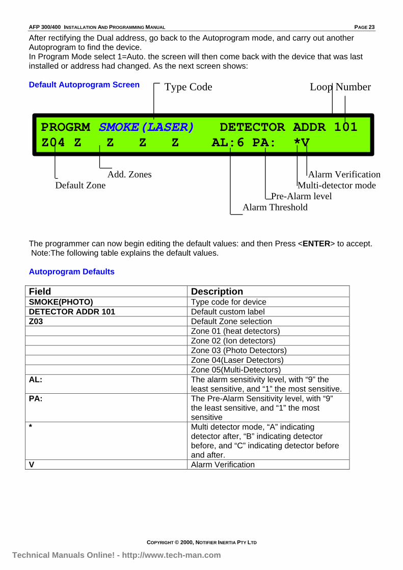
After rectifying the Dual address, go back to the Autoprogram mode, and carry out anotherAutoprogram to find the device.In Program Mode select 1=Auto. the screen will then come back with the device that was lastinstalled or address had changed. As the next screen shows:
Default Autoprogram Screen
The programmer can now begin editing the default values: and then Press <ENTER> to accept. Note:The following table explains the default values.
Autoprogram Defaults
Field DescriptionSMOKE(PHOTO) Type code for deviceDETECTOR ADDR 101 Default custom labelZ03 Default Zone selection
Zone 01 (heat detectors)Zone 02 (Ion detectors)Zone 03 (Photo Detectors)Zone 04(Laser Detectors)Zone 05(Multi-Detectors)
AL: The alarm sensitivity level, with “9” theleast sensitive, and “1” the most sensitive.
PA: The Pre-Alarm Sensitivity level, with “9”the least sensitive, and “1” the mostsensitive
* Multi detector mode, “A” indicatingdetector after, “B” indicating detectorbefore, and “C” indicating detector beforeand after.
V Alarm Verification
PROGRM SSMMOOKKEE((LLAASSEERR)) DETECTOR ADDR 101Z04 Z Z Z Z AL:6 PA: *V
Type Code Loop Number
Add. Zones Alarm Verification Default Zone Multi-detector mode Pre-Alarm level Alarm Threshold
Technical Manuals Online! - http://www.tech-man.com

PAGE 24 AFP 300/400 INSTALLATION AND PROGRAMMING MANUAL
COPYRIGHT © 2000, NOTIFIER INERTIA PTY LTD
Autoprogram- Device no longer neededIf a detector exists in the control panel program, but is missing (no response from the device),the control panel will display the following:
To delete the device, press <ENTER>To keep the device, press <ESC>
Installing a DeviceAddress the device to a spare address and connect to the loop, then carry out an Autoprogramfunction to find the device. Modify the default values to suit. See Autoprogram Section above.
Edit a PointSelect 2=POINT. From the Program Mode screen.You can now modify or delete a point. To modify a point for a detector, module, or output circuit,press <1> to display the Modify Point screen, or press <2> to display the Delete Point screen.
PLEASE NOTE:For information on Type Code’s please see the section Type Code (ID’s)
Modifying a PointPress <1> to modify a point the screen will now show:
Press the Detector key, then enter the address of the detector you wish to edit, and press<ENTER> :Once a Device is selected the screen will now show:
You can now change the Type Code, the detectors description, the Zones mapped to thatdetector, the alarm level, the pre-alarm level, the multi-mode function and the Verification.
PLEASE NOTE:For information on Type Code’s please see the section Type Code (ID’s)
* multi detector mode described next.
POINT PROG. 1=MODIFY POINT2=DELETE POINT
POINT PROG. ENTER: DETECTOR=*,AAA.EMODULE=#,AAA,E
PROGRM SSMMOOKKEE((LLAASSEERR)) DETECTOR ADDR 101Z04 Z Z Z Z AL:6 PA: *V D101
PROGRM SMOKE(PHOTO) DETECTOR ADDR 133DEVICE NOT ANSWERING DELETE FR MEM? D133
Technical Manuals Online! - http://www.tech-man.com
AFP 300/400 INSTALLATION AND PROGRAMMING MANUAL PAGE 25
COPYRIGHT © 2000, NOTIFIER INERTIA PTY LTD
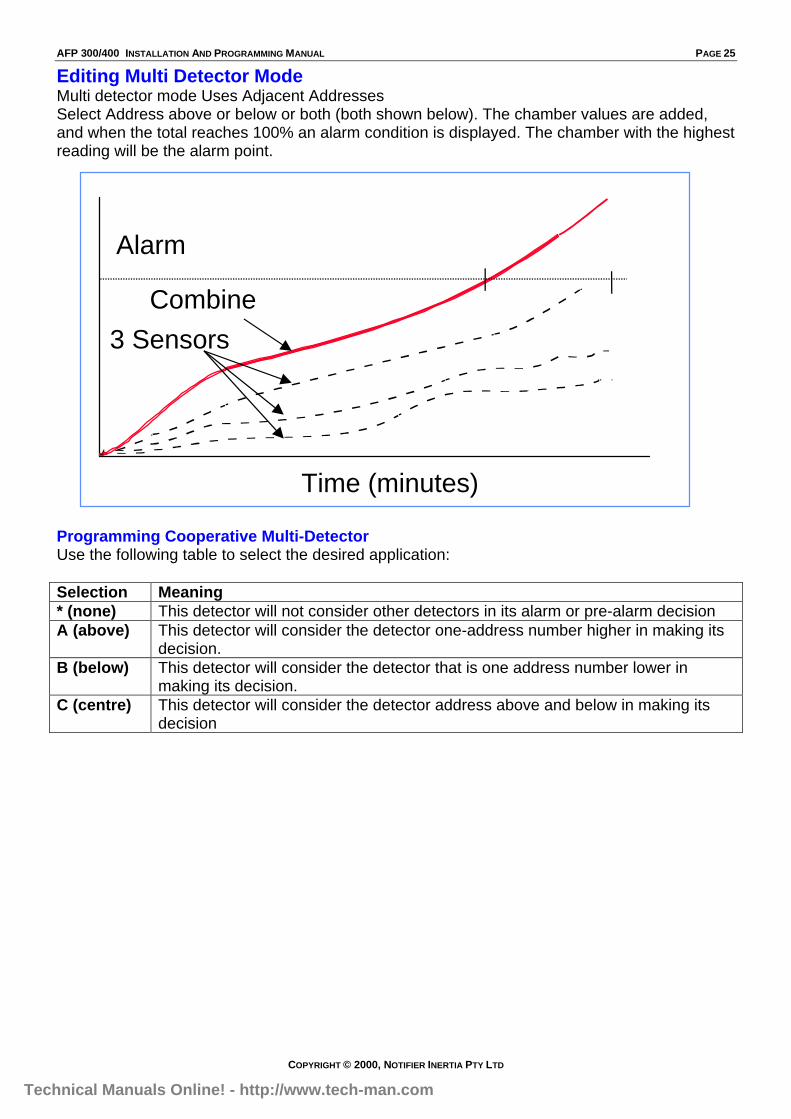
Editing Multi Detector ModeMulti detector mode Uses Adjacent AddressesSelect Address above or below or both (both shown below). The chamber values are added,and when the total reaches 100% an alarm condition is displayed. The chamber with the highestreading will be the alarm point.
Programming Cooperative Multi-DetectorUse the following table to select the desired application:
Selection Meaning* (none) This detector will not consider other detectors in its alarm or pre-alarm decisionA (above) This detector will consider the detector one-address number higher in making its
decision.B (below) This detector will consider the detector that is one address number lower in
making its decision.C (centre) This detector will consider the detector address above and below in making its
decision
Alarm
Combine
Time (minutes)
3 Sensors
Technical Manuals Online! - http://www.tech-man.com
PAGE 26 AFP 300/400 INSTALLATION AND PROGRAMMING MANUAL
COPYRIGHT © 2000, NOTIFIER INERTIA PTY LTD
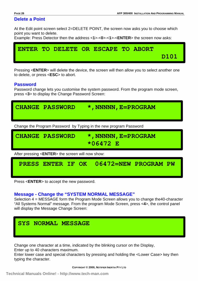
Delete a Point
At the Edit point screen select 2=DELETE POINT, the screen now asks you to choose whichpoint you want to delete.Example: Press Detector then the address <1>-<0>-<1>-<ENTER> the screen now asks:
Pressing <ENTER> will delete the device, the screen will then allow you to select another oneto delete, or press <ESC> to abort.
PasswordPassword change lets you customise the system password. From the program mode screen,press <3> to display the Change Password Screen:
Change the Program Password by Typing in the new program Password
After pressing <ENTER> the screen will now show:
Press <ENTER> to accept the new password.
Message - Change the “SYSTEM NORMAL MESSAGE”Selection 4 = MESSAGE form the Program Mode Screen allows you to change the40-character“All Systems Normal” message. From the program Mode Screen, press <4>, the control panelwill display the Message Change Screen:
Change one character at a time, indicated by the blinking cursor on the Display,Enter up to 40 characters maximum.Enter lower case and special characters by pressing and holding the <Lower Case> key thentyping the character.
ENTER TO DELETE OR ESCAPE TO ABORTD101
CHANGE PASSWORD *,NNNNN,E=PROGRAM
CHANGE PASSWORD *,NNNNN,E=PROGRAM*06472 E
PRESS ENTER IF OK 06472=NEW PROGRAM PW
SYS NORMAL MESSAGE
Technical Manuals Online! - http://www.tech-man.com
AFP 300/400 INSTALLATION AND PROGRAMMING MANUAL PAGE 27
COPYRIGHT © 2000, NOTIFIER INERTIA PTY LTD
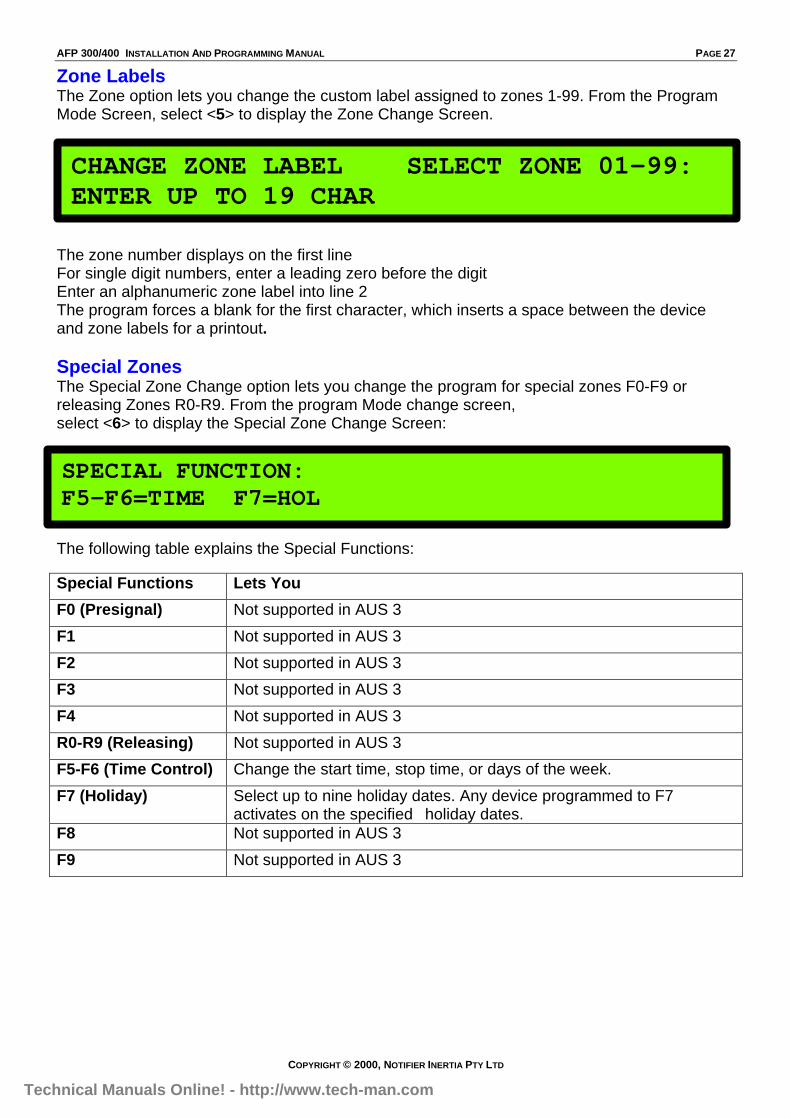
Zone LabelsThe Zone option lets you change the custom label assigned to zones 1-99. From the ProgramMode Screen, select <5> to display the Zone Change Screen.
The zone number displays on the first lineFor single digit numbers, enter a leading zero before the digitEnter an alphanumeric zone label into line 2The program forces a blank for the first character, which inserts a space between the deviceand zone labels for a printout.
Special ZonesThe Special Zone Change option lets you change the program for special zones F0-F9 orreleasing Zones R0-R9. From the program Mode change screen,select <6> to display the Special Zone Change Screen:
The following table explains the Special Functions:
Special Functions Lets You
F0 (Presignal) Not supported in AUS 3
F1 Not supported in AUS 3
F2 Not supported in AUS 3
F3 Not supported in AUS 3
F4 Not supported in AUS 3
R0-R9 (Releasing) Not supported in AUS 3
F5-F6 (Time Control) Change the start time, stop time, or days of the week.
F7 (Holiday) Select up to nine holiday dates. Any device programmed to F7activates on the specified holiday dates.
F8 Not supported in AUS 3
F9 Not supported in AUS 3
CHANGE ZONE LABEL SELECT ZONE 01-99:ENTER UP TO 19 CHAR
SPECIAL FUNCTION:F5-F6=TIME F7=HOL
Technical Manuals Online! - http://www.tech-man.com
PAGE 28 AFP 300/400 INSTALLATION AND PROGRAMMING MANUAL
COPYRIGHT © 2000, NOTIFIER INERTIA PTY LTD
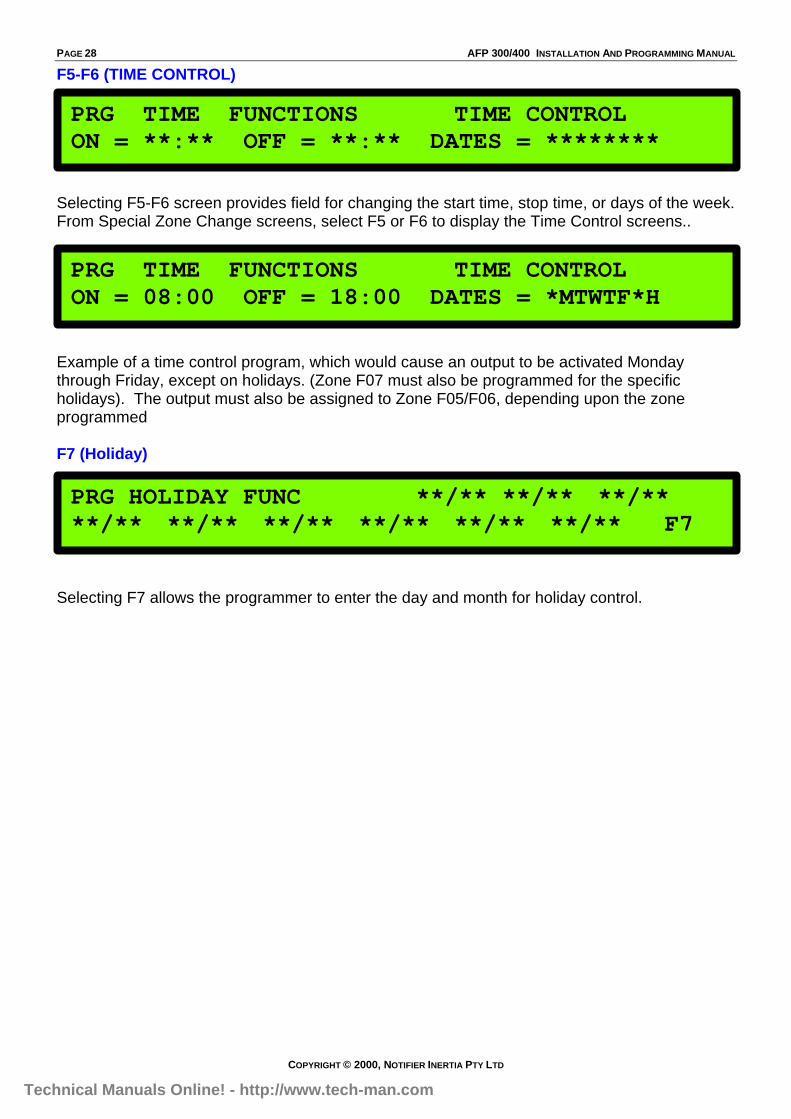
F5-F6 (TIME CONTROL)
Selecting F5-F6 screen provides field for changing the start time, stop time, or days of the week.From Special Zone Change screens, select F5 or F6 to display the Time Control screens..
Example of a time control program, which would cause an output to be activated Mondaythrough Friday, except on holidays. (Zone F07 must also be programmed for the specificholidays). The output must also be assigned to Zone F05/F06, depending upon the zoneprogrammed
F7 (Holiday)
Selecting F7 allows the programmer to enter the day and month for holiday control.
PRG TIME FUNCTIONS TIME CONTROLON = **:** OFF = **:** DATES = ********
F05
PRG TIME FUNCTIONS TIME CONTROLON = 08:00 OFF = 18:00 DATES = *MTWTF*H
PRG HOLIDAY FUNC **/** **/** **/****/** **/** **/** **/** **/** **/** F7
Technical Manuals Online! - http://www.tech-man.com

AFP 300/400 INSTALLATION AND PROGRAMMING MANUAL PAGE 29
COPYRIGHT © 2000, NOTIFIER INERTIA PTY LTD
System FunctionsThe System option lets you set general system functions. From the program mode screen,select <7> to display the System Functions screen:
System Function Setting DefaultSIL INH 0 to 300 seconds 0AUTO 0 = none, 600 to 900 seconds 0VERIFY 0 to 30 seconds 0AUS TIME USA TIME (with Next/Previous keys). AUS TIME
European time format changes to 24-hour time, and places the day beforethe month
TERM_SUPERV NO or YES NOLoc T Loc M (Local-Terminal Mode)
Rem T (Remote Terminal Status)Loc T
BLINK=Y Set to Blink=N (no blink) Blink=YST=4 ST=6 (Style 6 wiring) ST=4ACS N or Y ACS=N
ACS =N ( Annunciators are discussed in the next section).
SIL INH=000 AUTO=000 VERIFY=30 AUS TIMETERM_SUPERV=NO LocT BLINK=Y ST=4 ACS=N
Technical Manuals Online! - http://www.tech-man.com
PAGE 30 AFP 300/400 INSTALLATION AND PROGRAMMING MANUAL
COPYRIGHT © 2000, NOTIFIER INERTIA PTY LTD
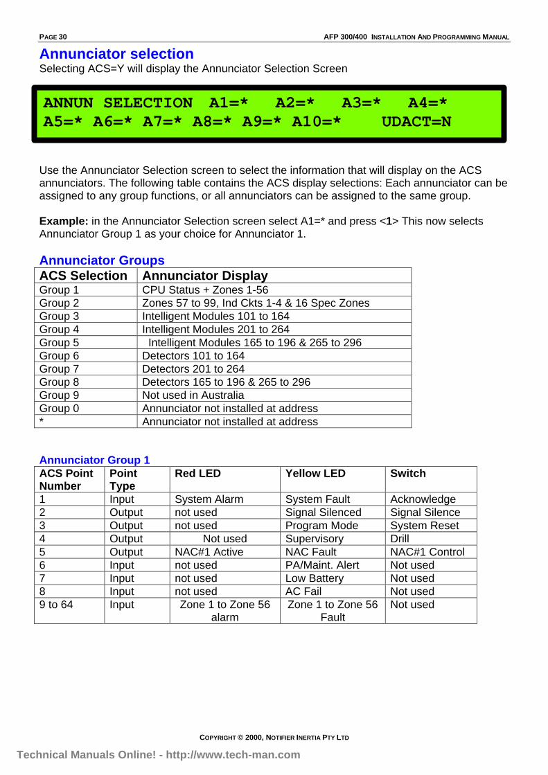
Annunciator selectionSelecting ACS=Y will display the Annunciator Selection Screen
Use the Annunciator Selection screen to select the information that will display on the ACSannunciators. The following table contains the ACS display selections: Each annunciator can beassigned to any group functions, or all annunciators can be assigned to the same group.
Example: in the Annunciator Selection screen select A1=* and press <1> This now selectsAnnunciator Group 1 as your choice for Annunciator 1.
Annunciator GroupsACS Selection Annunciator DisplayGroup 1 CPU Status + Zones 1-56Group 2 Zones 57 to 99, Ind Ckts 1-4 & 16 Spec ZonesGroup 3 Intelligent Modules 101 to 164Group 4 Intelligent Modules 201 to 264Group 5 Intelligent Modules 165 to 196 & 265 to 296Group 6 Detectors 101 to 164Group 7 Detectors 201 to 264Group 8 Detectors 165 to 196 & 265 to 296Group 9 Not used in AustraliaGroup 0 Annunciator not installed at address* Annunciator not installed at address
Annunciator Group 1ACS PointNumber
PointType
Red LED Yellow LED Switch
1 Input System Alarm System Fault Acknowledge2 Output not used Signal Silenced Signal Silence3 Output not used Program Mode System Reset4 Output Not used Supervisory Drill5 Output NAC#1 Active NAC Fault NAC#1 Control6 Input not used PA/Maint. Alert Not used7 Input not used Low Battery Not used8 Input not used AC Fail Not used9 to 64 Input Zone 1 to Zone 56
alarmZone 1 to Zone 56
FaultNot used
ANNUN SELECTION A1=* A2=* A3=* A4=*A5=* A6=* A7=* A8=* A9=* A10=* UDACT=N
Technical Manuals Online! - http://www.tech-man.com

AFP 300/400 INSTALLATION AND PROGRAMMING MANUAL PAGE 31
COPYRIGHT © 2000, NOTIFIER INERTIA PTY LTD
Annunciator Group 2ACS PointNumber
PointType
Red LED Yellow LED Switch
1 to 43 Input Zone 57 to 99Active
Zone 57 to 99Fault
Not used
44 to 52 Output Zones F1 to F9Active
Zones F1 to F9Fault
Not used
53 to 60 Output Zones R0 to R7Active
Zones R0 to R7Fault
Not used
6162
OutputOutput
NAC 1 ActiveNAC 2 Active
NAC 1 FaultNAC 2 Fault
NAC 1 ControlNAC 2 Control
6364
OutputOutput
NAC 3 ActiveNAC 4 Active
NAC 3 FaultNAC 4 Fault
NAC 3 ControlNAC 4 Control
Annunciator Group 3-5ACS PointNumber
PointType
Red LED Yellow LED Switch
Group 31 to 64
Input orOutput
Modules 101 to 164Active
Modules 101 to164 Fault
Control ModuleOperation
Group 41 to 64AFP-400
Input orOutputOnly
Modules 201 to 264Active
Modules 201 to264 Fault
Control ModuleOperation
Group 51 to 32
Input orOutput
Modules 165 to 196Active
Modules 165 to196 Fault
Control ModuleOperation
Group 533 to 64AFP-400
Input orOutputOnly
Modules 265 to 296Active
Modules 265 to296 Fault
Control ModuleOperation
Annunciator Group 6 – 8ACS PointNumber
PointType
Red LED Yellow LED Switch
Group 61 to 64
Input Detectors 101 to 164Alarm
Detectors 101 to164 Fault
Not used
Group 71 to 64AFP-400
Input
Only
Detectors 201 to 264Alarm
Detectors 201 to264 Fault
Not used
Group 81 to 32
Input Detectors 165 to 196Alarm
Detectors 165 to196 Fault
Not used
Group 833 to 64AFP-400
Input
Only
Detectors 265 to 296Alarm
Detectors 265 to296 Fault
Not used
Technical Manuals Online! - http://www.tech-man.com
PAGE 32 AFP 300/400 INSTALLATION AND PROGRAMMING MANUAL
COPYRIGHT © 2000, NOTIFIER INERTIA PTY LTD
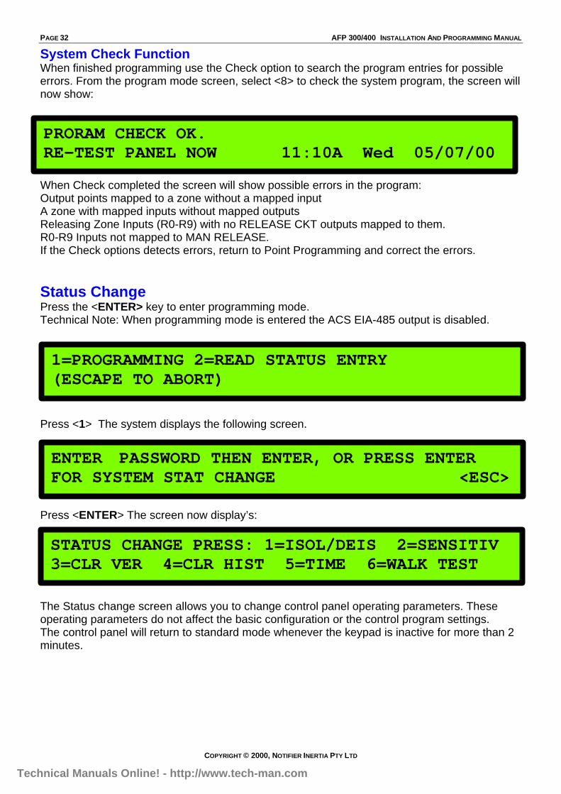
System Check FunctionWhen finished programming use the Check option to search the program entries for possibleerrors. From the program mode screen, select <8> to check the system program, the screen willnow show:
When Check completed the screen will show possible errors in the program:Output points mapped to a zone without a mapped inputA zone with mapped inputs without mapped outputsReleasing Zone Inputs (R0-R9) with no RELEASE CKT outputs mapped to them.R0-R9 Inputs not mapped to MAN RELEASE.If the Check options detects errors, return to Point Programming and correct the errors.
Status ChangePress the <ENTER> key to enter programming mode.Technical Note: When programming mode is entered the ACS EIA-485 output is disabled.
Press <1> The system displays the following screen.
Press <ENTER> The screen now display’s:
The Status change screen allows you to change control panel operating parameters. Theseoperating parameters do not affect the basic configuration or the control program settings.The control panel will return to standard mode whenever the keypad is inactive for more than 2minutes.
PRORAM CHECK OK.RE-TEST PANEL NOW 11:10A Wed 05/07/00
STATUS CHANGE PRESS: 1=ISOL/DEIS 2=SENSITIV3=CLR VER 4=CLR HIST 5=TIME 6=WALK TEST
1=PROGRAMMING 2=READ STATUS ENTRY(ESCAPE TO ABORT)
ENTER PASSWORD THEN ENTER, OR PRESS ENTERFOR SYSTEM STAT CHANGE <ESC> *****
Technical Manuals Online! - http://www.tech-man.com

AFP 300/400 INSTALLATION AND PROGRAMMING MANUAL PAGE 33
COPYRIGHT © 2000, NOTIFIER INERTIA PTY LTD
Isolate a Device or ZoneSelect <1> from the Status Change screen to display the ISO/DE-ISO Screen
Enter the address of the point, then press <ENTER>. Example:- Select the point type: * fordetectors Then Press <1>-<0>-<1>-<ENTER> A sample display is:
You can Isolate or De-isolate a point by pressing the next button this will change the ‘Blinkingstatus banner’.Please Note; The same can be done for Modules and Zones.
Change SensitivitySelect <2> from the Status Change screen to display the Detector Sensitivity screen.
Enter the address of an installed detector and the control panel displays the following screen:
The values for Alarm Level are 1-9, 1 most sensitiveThe values for Pre-Alarm are 0-9, 1 most sensitive, 0 no pre-alarm.
Note: For nominal Sensitivity levels after an Autoprogram see Pages 39-41.Or to automatically change Seneitivity levels at a given time see ‘Automatically
Change sensitivity’ on page 38
Clear Verification CountersSelect <3> from the Status Change screen to clear all verification tally counters for detectorsselected for alarm verifications.
Pressing <ENTER> will clear the all verification countersPressing <ESC> to return to the Status Change screen without clearing.
ZONE=Z,AA,E DETECTOR=*,AAA,EMODULE=#,AAA,E
ISOLATE SMOKE(PHOTO) DETECTOR ADDR 101Z01 Z02 Z03 Z04 Z05 AL:5
** D101
PRESS ENTER TO CLEAR VERIFICATION COUNTS OR ESCAPE TO ABORT
DET. SENS & COMP. ENTER POINTS:AAA,E
PROGRM SMOKE (PHOTO) DETECTOR ADDR 101Z03 Z04 Z05 Z06 Z85 AL:5 PA:7 ** D101
Technical Manuals Online! - http://www.tech-man.com
PAGE 34 AFP 300/400 INSTALLATION AND PROGRAMMING MANUAL
COPYRIGHT © 2000, NOTIFIER INERTIA PTY LTD
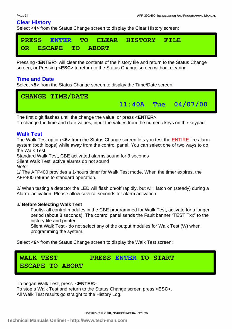
Clear HistorySelect <4> from the Status Change screen to display the Clear History screen:
Pressing <ENTER> will clear the contents of the history file and return to the Status Changescreen, or Pressing <ESC> to return to the Status Change screen without clearing.
Time and DateSelect <5> from the Status Change screen to display the Time/Date screen:
The first digit flashes until the change the value, or press <ENTER>.To change the time and date values, input the values from the numeric keys on the keypad
Walk TestThe Walk Test option <6> from the Status Change screen lets you test the ENTIRE fire alarmsystem (both loops) while away from the control panel. You can select one of two ways to dothe Walk Test.Standard Walk Test, CBE activated alarms sound for 3 secondsSilent Walk Test, active alarms do not soundNote:1/ The AFP400 provides a 1-hours timer for Walk Test mode. When the timer expires, theAFP400 returns to standard operation.
2/ When testing a detector the LED will flash on/off rapidly, but will latch on (steady) during aAlarm activation. Please allow several seconds for alarm activation.
3/ Before Selecting Walk TestFaults- all control modules in the CBE programmed for Walk Test, activate for a longerperiod (about 8 seconds). The control panel sends the Fault banner “TEST Txx” to thehistory file and printer.Silent Walk Test - do not select any of the output modules for Walk Test (W) whenprogramming the system.
Select <6> from the Status Change screen to display the Walk Test screen:
To began Walk Test, press <ENTER>.To stop a Walk Test and return to the Status Change screen press <ESC>.All Walk Test results go straight to the History Log.
PRESS ENTER TO CLEAR HISTORY FILEOR ESCAPE TO ABORT
CHANGE TIME/DATE 11:40A Tue 04/07/00
WALK TEST PRESS ENTER TO STARTESCAPE TO ABORT
Technical Manuals Online! - http://www.tech-man.com
AFP 300/400 INSTALLATION AND PROGRAMMING MANUAL PAGE 35
COPYRIGHT © 2000, NOTIFIER INERTIA PTY LTD
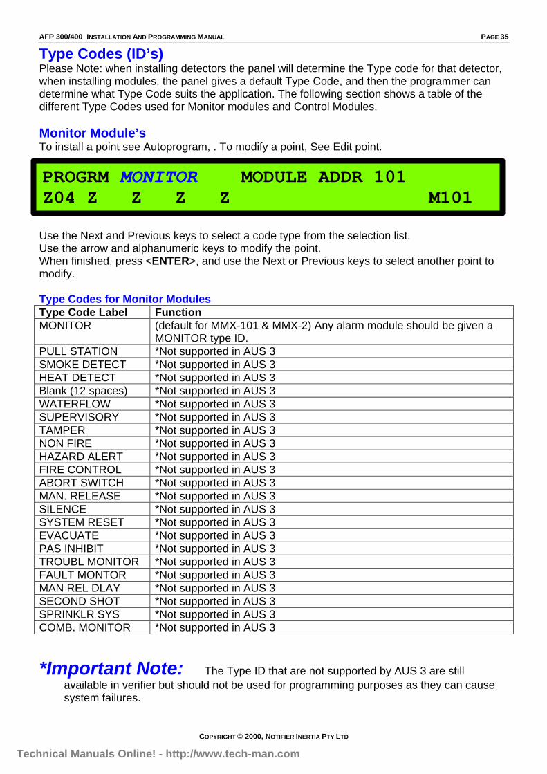
Type Codes (ID’s)Please Note: when installing detectors the panel will determine the Type code for that detector,when installing modules, the panel gives a default Type Code, and then the programmer candetermine what Type Code suits the application. The following section shows a table of thedifferent Type Codes used for Monitor modules and Control Modules.
Monitor Module’sTo install a point see Autoprogram, . To modify a point, See Edit point.
Use the Next and Previous keys to select a code type from the selection list.Use the arrow and alphanumeric keys to modify the point.When finished, press <ENTER>, and use the Next or Previous keys to select another point tomodify.
Type Codes for Monitor ModulesType Code Label FunctionMONITOR (default for MMX-101 & MMX-2) Any alarm module should be given a
MONITOR type ID.PULL STATION *Not supported in AUS 3SMOKE DETECT *Not supported in AUS 3HEAT DETECT *Not supported in AUS 3Blank (12 spaces) *Not supported in AUS 3WATERFLOW *Not supported in AUS 3SUPERVISORY *Not supported in AUS 3TAMPER *Not supported in AUS 3NON FIRE *Not supported in AUS 3HAZARD ALERT *Not supported in AUS 3FIRE CONTROL *Not supported in AUS 3ABORT SWITCH *Not supported in AUS 3MAN. RELEASE *Not supported in AUS 3SILENCE *Not supported in AUS 3SYSTEM RESET *Not supported in AUS 3EVACUATE *Not supported in AUS 3PAS INHIBIT *Not supported in AUS 3TROUBL MONITOR *Not supported in AUS 3FAULT MONTOR *Not supported in AUS 3MAN REL DLAY *Not supported in AUS 3SECOND SHOT *Not supported in AUS 3SPRINKLR SYS *Not supported in AUS 3COMB. MONITOR *Not supported in AUS 3
*Important Note: The Type ID that are not supported by AUS 3 are stillavailable in verifier but should not be used for programming purposes as they can causesystem failures.
PROGRM MONITOR MODULE ADDR 101Z04 Z Z Z Z M101
Technical Manuals Online! - http://www.tech-man.com
PAGE 36 AFP 300/400 INSTALLATION AND PROGRAMMING MANUAL
COPYRIGHT © 2000, NOTIFIER INERTIA PTY LTD
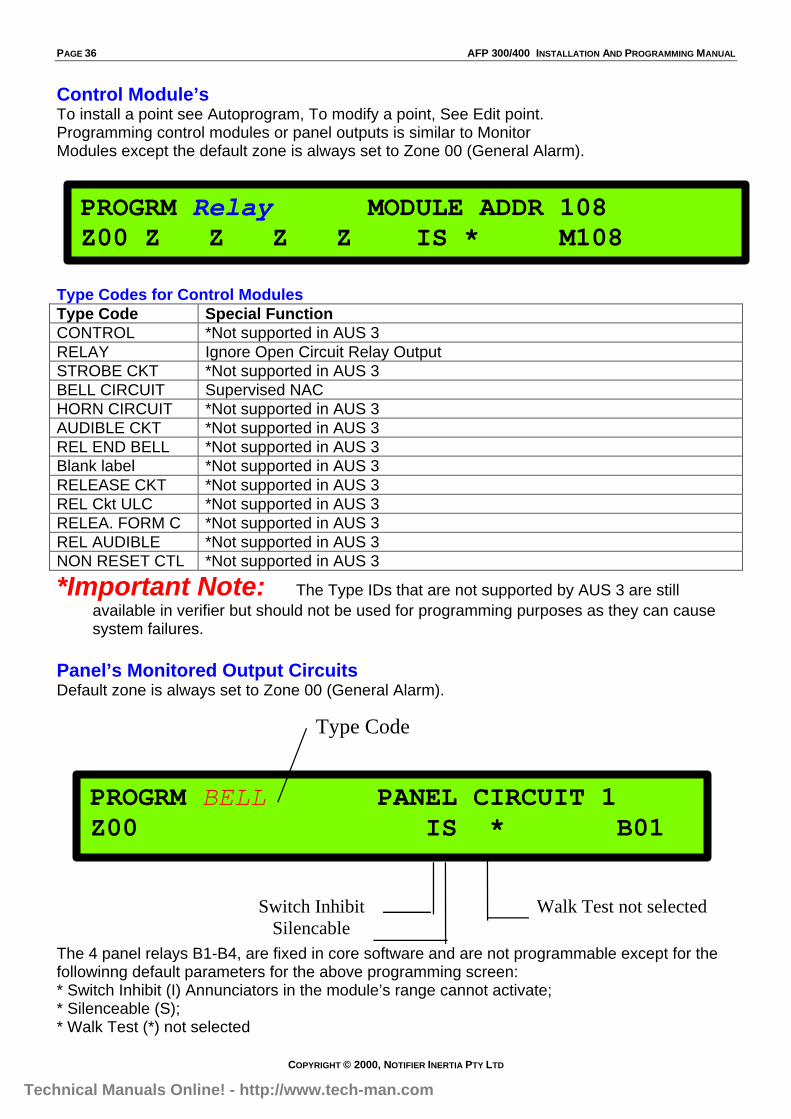
Control Module’sTo install a point see Autoprogram, To modify a point, See Edit point.Programming control modules or panel outputs is similar to MonitorModules except the default zone is always set to Zone 00 (General Alarm).
Type Codes for Control ModulesType Code Special FunctionCONTROL *Not supported in AUS 3RELAY Ignore Open Circuit Relay OutputSTROBE CKT *Not supported in AUS 3BELL CIRCUIT Supervised NACHORN CIRCUIT *Not supported in AUS 3AUDIBLE CKT *Not supported in AUS 3REL END BELL *Not supported in AUS 3Blank label *Not supported in AUS 3RELEASE CKT *Not supported in AUS 3REL Ckt ULC *Not supported in AUS 3RELEA. FORM C *Not supported in AUS 3REL AUDIBLE *Not supported in AUS 3NON RESET CTL *Not supported in AUS 3
*Important Note: The Type IDs that are not supported by AUS 3 are stillavailable in verifier but should not be used for programming purposes as they can causesystem failures.
Panel’s Monitored Output CircuitsDefault zone is always set to Zone 00 (General Alarm).
The 4 panel relays B1-B4, are fixed in core software and are not programmable except for thefollowinng default parameters for the above programming screen:* Switch Inhibit (I) Annunciators in the module’s range cannot activate;* Silenceable (S);* Walk Test (*) not selected
PROGRM Relay MODULE ADDR 108Z00 Z Z Z Z IS * M108
PROGRM BELL PANEL CIRCUIT 1Z00 IS * B01
Type Code
Switch Inhibit Walk Test not selected Silencable
Technical Manuals Online! - http://www.tech-man.com

AFP 300/400 INSTALLATION AND PROGRAMMING MANUAL PAGE 37
COPYRIGHT © 2000, NOTIFIER INERTIA PTY LTD
Control-By-Event ProgrammingCBE EquationEach input can be assigned up to five different software zones (1-99 or SPL Zones). All inputsare also assigned to Z00 (General Alarm Bus), which insure that any Fire Alarm Device willactivate a Fire Alarm condition. Note that all inputs have default zone assignments.Each output can be assigned from one to five different software zones (1-99 or SPL Zones).A zone can have no input/output assigned, or unlimited inputs/outputs may be assigned to onezone. Note that zone status is also transmitted on the EIA-485 circuits to ACS Group 1, P9-P64
Automatically Change sensitivityEach input can be assigned up to five different zones, including special zones. If theprogrammer wanted the CPU-400 to automatically adjust a detector sensitivity to the lowestselection (9) during a specific time period/day, he would assign that detector to Zone F05/F06,and define the time or day period in Zone F05/F06 programming.
ZoneInput Output
ZoneF05/06Detector
Technical Manuals Online! - http://www.tech-man.com
PAGE 38 AFP 300/400 INSTALLATION AND PROGRAMMING MANUAL
COPYRIGHT © 2000, NOTIFIER INERTIA PTY LTD
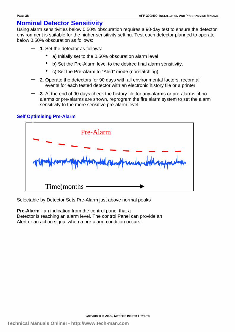
Nominal Detector SensitivityUsing alarm sensitivities below 0.50% obscuration requires a 90-day test to ensure the detectorenvironment is suitable for the higher sensitivity setting. Test each detector planned to operatebelow 0.50% obscuration as follows:
– 1. Set the detector as follows:
• a) Initially set to the 0.50% obscuration alarm level
• b) Set the Pre-Alarm level to the desired final alarm sensitivity.
• c) Set the Pre-Alarm to “Alert” mode (non-latching)
– 2. Operate the detectors for 90 days with all environmental factors, record all events for each tested detector with an electronic history file or a printer.
– 3. At the end of 90 days check the history file for any alarms or pre-alarms, if noalarms or pre-alarms are shown, reprogram the fire alarm system to set the alarmsensitivity to the more sensitive pre-alarm level.
Self Optimising Pre-Alarm
Selectable by Detector Sets Pre-Alarm just above normal peaks
Pre-Alarm - an indication from the control panel that aDetector is reaching an alarm level. The control Panel can provide anAlert or an action signal when a pre-alarm condition occurs.
Time(months)
Pre-AlarmThreshold
Technical Manuals Online! - http://www.tech-man.com

AFP 300/400 INSTALLATION AND PROGRAMMING MANUAL PAGE 39
COPYRIGHT © 2000, NOTIFIER INERTIA PTY LTD
Sensitivity Levels for the AFP-400: (Graph)
Photo Optical Pre-Alarm Sensitivity
PRE-AL:9
PRE-AL;8
PRE-AL;7
PRE-AL;6
PRE-AL;5
PRE-AL;4
PRE-AL;3
PRE-AL;2
PRE-AL;1
Photo Optical Detector.49%
1.6%
.67%
1.0%
2.5%
3.3%
4.2%
5.0%
Auto- The control panel selects a suitable Pre-Alarm level for a detector.
Photo Optical Alarm Sensitivity
AL:9
AL;8
AL;7
AL;6
AL;5
AL;4
AL;3
AL;2
AL;1
Photo Optical Detector
0.6%
1.6%
4.1%
2.5%
3.3%
4.9%
5.8%
6.6%
7.8%
Technical Manuals Online! - http://www.tech-man.com
PAGE 40 AFP 300/400 INSTALLATION AND PROGRAMMING MANUAL
COPYRIGHT © 2000, NOTIFIER INERTIA PTY LTD
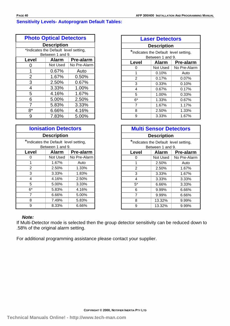
Sensitivity Levels- Autoprogram Default Tables:
Photo Optical DetectorsDescription
*Indicates the Default level setting,Between 1 and 9.
Level Alarm Pre-alarm0 Not Used No Pre-Alarm
1 0.67% Auto2 1.67% 0.50%3 2.50% 0.67%4 3.33% 1.00%5 4.16% 1.67%6 5.00% 2.50%7 5.83% 3.33%8* 6.66% 4.16%9 7.83% 5.00%
Ionisation DetectorsDescription
*Indicates the Default level setting,Between 1 and 9.
Level Alarm Pre-alarm0 Not Used No Pre-Alarm1 1.67% Auto2 2.50% 1.33%3 3.33% 1.83%4 4.16% 2.50%5 5.00% 3.33%6* 5.83% 4.16%7 6.66% 5.00%8 7.49% 5.83%9 8.33% 6.66%
Laser DetectorsDescription
*Indicates the Default level setting,Between 1 and 9.
Level Alarm Pre-alarm0 Not Used No Pre-Alarm1 0.10% Auto2 0.17% 0.07%3 0.33% 0.10%4 0.67% 0.17%5 1.00% 0.33%6* 1.33% 0.67%7 1.67% 1.17%8 2.50% 1.33%9 3.33% 1.67%
Multi Sensor DetectorsDescription
*Indicates the Default level setting,Between 1 and 9.
Level Alarm Pre-alarm0 Not Used No Pre-Alarm1 2.50% Auto2 2.50% 1.67%3 3.33% 1.67%4 3.33% 3.33%5* 6.66% 3.33%6 9.99% 6.66%7 9.99% 6.66%8 13.32% 9.99%9 13.32% 9.99%
Note:If Multi-Detector mode is selected then the group detector sensitivity can be reduced down to.58% of the original alarm setting.
For additional programming assistance please contact your supplier.
Technical Manuals Online! - http://www.tech-man.com