Embed Size (px)
Citation preview
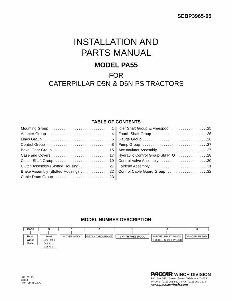
INSTALLATION AND PARTS MANUAL
MODEL PA55 FOR
CATERPILLAR D5N & D6N PS TRACTORS
TABLE OF CONTENTSMounting Group . . . . . . . . . . . . . . . . . . . . . . . . . . . . . .1Adapter Group . . . . . . . . . . . . . . . . . . . . . . . . . . . . . . .4Lines Group . . . . . . . . . . . . . . . . . . . . . . . . . . . . . . . . .5Control Group . . . . . . . . . . . . . . . . . . . . . . . . . . . . . . .8Bevel Gear Group . . . . . . . . . . . . . . . . . . . . . . . . . . .15Case and Covers . . . . . . . . . . . . . . . . . . . . . . . . . . . .17Clutch Shaft Group . . . . . . . . . . . . . . . . . . . . . . . . . .19Clutch Assembly (Slotted Housing) . . . . . . . . . . . . . .21Brake Assembly (Slotted Housing) . . . . . . . . . . . . . .22Cable Drum Group . . . . . . . . . . . . . . . . . . . . . . . . . .23
Idler Shaft Group w/Freespool . . . . . . . . . . . . . . . . .25Fourth Shaft Group . . . . . . . . . . . . . . . . . . . . . . . . . .26Gauge Group . . . . . . . . . . . . . . . . . . . . . . . . . . . . . . .26Pump Group . . . . . . . . . . . . . . . . . . . . . . . . . . . . . . .27Accumulator Assembly . . . . . . . . . . . . . . . . . . . . . . .27Hydraulic Control Group-Std PTO . . . . . . . . . . . . . . .28Control Valve Assembly . . . . . . . . . . . . . . . . . . . . . . .30Fairlead Assembly . . . . . . . . . . . . . . . . . . . . . . . . . . .31Control Cable Guard Group . . . . . . . . . . . . . . . . . . .32
PACR WINCH DIVISION
www.paccarwinch.com
P.O. Box 547 Broken Arrow, Oklahoma 74013PHONE: (918) 251-8511 FAX: (918) 259-1575
E-2.79:1Model
0 0
0-FOUR SHAFT WINCH 0-NO FAIRLEAD1-THREE SHAFT WINCH
1-WITH FREESPOOLWinch Gear Ratio
D-2.11:1
1
Basic Bevel 0-OVERWIND 0-STANDARD BRAKE
PA55 0 0D
MODEL NUMBER DESCRIPTION
SEBP3965-05
LIT2126 R57/2010PRINTED IN U.S.A.

MODEL PA55MOUNTING GROUPD5N & D6N
ITEM PART NO. DESCRIPTION QTY11 224-1118 PILOT, PTO 112 8S-5654 O-RING 313 5P-2228 CAPSCREW, HEX HD (1/2 - 13 UNC x 1.00, GD 8, Z) 414 8T-4223 WASHER, HARD, Z (1/2) 415 120-7671 RETAINING RING 216 224-1144 SHAFT, PTO 117 118-6539 COUPLING 118 8T-6430 CAPSCREW, HEX HD (M20 X 2.5 X 50, GD 10.9, Z) 1419 8T-3282 WASHER, HARD, Z (M20) 1420 188-7404 GUARD 121 5P-2566 CAPSCREW, HEX HD (1/2 -13 NC X 1 1/2, GD 8, Z) 422 5P-1076 WASHER, HARD, Z (1/2) 4
1

MODEL PA55MOUNTING GROUP
D5N & D6N
2
NOTES
1. PTO rotation is CCW as viewed from rear of tractor.2. PTO pilot, (11) is used in several applications, usu-
ally only one o-ring (12) will engage and seal in thetractor PTO opening.
3. Ensure that installation instructions are completedbefore the Loc-tite thread locking compound hard-ens.
4. Remove paint, rust, dirt and oil from mounting sur-faces of winch, tractor and winch adapters. If nec-essary, clean tapped holes in tractor rear face toensure full thread engagement.
5. All fasteners that will be installed with thread lock-ing compound must be thoroughly cleaned with sol-vent to remove all traces of oil.
INSTRUCTIONS1. Remove the transmission filter group and mounting
brackets and fuel drain group from rear of tractor.The winch mounting brackets must be installed onthe tractor and the revised transmission filter groupinstalled onto the winch mounting brackets prior toinstalling the winch.
2. Apply Loc-tite 242, 243 or equivalent to the cleandry threads of capscrews (18). Lift the mountingbrackets into position and install capscrews withwashers (18 & 19). Tighten capscrews only handtight at this time. Capscrews will be tightened to fulltorque after winch is installed on brackets.
3. Install the transmission filter and fuel drain groups(ref. 189-3144 for D5N and 200-6975 for D6N) ontowinch mounting brackets as shown.
4. Apply Loc-tite 271 or equivalent to approximately1.5 in. (38 mm) of bracket-end of studs (6). Installstuds into top holes of mounting brackets (1, 2) to aprojection height of 3.75 in. (95.3 mm).
5. Install spacers (3) onto studs as shown.6. Install o-rings (12) onto PTO pilot (11) and coat with
general purpose grease.7. Apply moly-type grease to the splines of the PTO
shaft (16) and install shaft into bevel pinion gear inwinch.
8. Install retaining rings (15) into grooves inside PTOcoupling (17). Install coupling onto PTO shaftinstalled in step 7, above. Install coupling withchamfered edge toward tractor.
9. Install o-rings (12) onto PTO pilot (11) and coat withgeneral purpose grease.
10. Lift winch into position and carefully align the winchPTO coupling with tractor PTO shaft. It may be nec-essary to turn the winch bevel gears by hand toassist alignment of the winch and tractor shafts.Remove the winch top cover to gain access to thebevel gears. Adjust winch position to minimize ver-tical and horizontal loads on PTO pilot.
11. Apply Loc-tite 242 or equivalent to the threads ofthe studs. Loosely install hardened flat washers andnuts (7, 8) onto studs.
12. Install spacers (3, 4) and angle bracket (5) betweenwinch case and mounting brackets.
13. Apply Loc-tite 242 or equivalent to the threads ofcapscrews (9) and install with washers (10) intowinch case.
14. Tighten nuts (7) to 600 lb-ft (815 N-m) and cap-screws (9) to 680 lb-ft (920 N-m) torque.
15. Evenly tighten capscrews (18) to 390 lb.-ft. (530 N-m) torque.
16. Fill winch to proper level with recommended oilbefore starting tractor. Refer to Operation &Preventive Maintenance Manual or Service Manualfor recommended oil.
Mounting brackets weigh approximately 140 pounds(64 kg). Make certain lifting equipment has adequatecapacity. Failure to use adequate lifting equipmentmay result in inury.
CAUTION
Winch weighs approximately 2,200 lb (1000 kg).Make certain lifting equipment has adequate capac-ity. Failure to use adequate lifting equipment mayresult in property damage, injury or death.

MODEL PA55ADAPTER GROUPD5N & D6N
3
ITEM PART NO. DESCRIPTION QTY1 224-1718 BRACKET, WINCH MOUNTING, RH 12 224-1719 BRACKET, WINCH MOUNTING, LH 13 224-1119 BLOCK, SPACER (1.00 THICK) 34 224-1725 BLOCK, SPACER (5/8 THICK) 15 188-7402 BRACKET 16 133-9225 STUD, ALL THREAD (1 1/8 - 7 UNC X 5.75, GD B7) 47 7X-0450 NUT, HEX (1 1/8 - 7 UNC, GD 8, Z) 48 7X-0531 WASHER, HARD, Z (1 1/8) 49 8T-8927 CAPSCREW, HEX HEAD (1-8 UNC X 3.75, GD 8, Z) 410 8T-5361 WASHER, HARD, Z (1 in.) 4

CATERPILLAR PA55 Winches on CATERPILLAR D5N/D6N Tractors
NOTE: Effective March 2004, CATERPILLAR has made a change to the transmission filterarrangement on the D5N and D6N tractors that will not allow for correct installation of theCATERPILLAR PA55 towing winches.
The new Filter Group, CATERPILLAR P/N 238-6809, must be replaced with the previousFilter Group, CATERPILLAR P/N 178-0568, to allow for correct fit and clearances for thewinch installation. Filter Group 178-0568 can be obtained through your local CATERPILLARdealer.
Beginning serial numbers on “non-winch ready” tractors shipped with the new filters are:ALH00347 D6N FTC XLAKM0676 D6N D/S XLALR00324 D6N FTC LGPALY00706 D6N D/S LGPAGG00700 D5N XLAKD00663 D5N LGP
“Winch-ready” tractors are factory-equipped with the correct filter assembly properly located,and do not require any additional changes.
4
MODEL PA55MOUNTING GROUP
D5N & D6N

10
18 23
9 20 14
1
1
16
7
4 2222
2430
13
31
12
11
MODEL PA55LINES GROUPD5N & D6N
5
165
282526
2X
1920
14
22
1
26
27
252X
3035 831 2
28
19
1723
29 30
D5N
18
18
33
3034 23
23
914
20
13
2
31
32
32
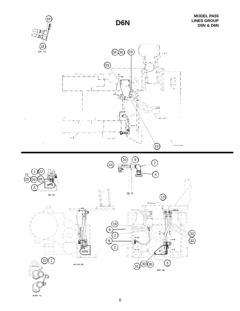
MODEL PA55LINES GROUP
D5N & D6ND6N
6
221
282625
5
2X
7
4
330 35
198
28
22 1

ITEM PART NO. DESCRIPTION QTY1 7K-1181 STRAP, CABLE 42 5P-4961 CLAMP-HOSE 23 237-7168 BRACKET 14 104861 * DRAIN VALVE 15 118-7809 PLATE 16 119-3450 SPACER 17 106-2105 ELBOW 18 164-5562 CONNECTOR ASSEMBLY 29 169-5863 ADAPTER ASSEMBLY 110 188-7397 BRACKET 111 188-7398 HOSE ASSEMBLY 112 188-7401 HOSE ASSEMBLY 113 196-2695 HARNESS ASSEMBLY 114 213-3745 ELBOW - 90° ORFS 116 148-8335 CONNECTOR ASSEMBLY 217 155-2026 UNION ASSEMBLY 118 164-5577 ELBOW ASSEMBLY 219 168-1969 ADAPTER ASSEMBLY 120 2P-1279 LOCKNUT (9/16 - 18) 122 4P-7428 CLIP 323 6V-9172 NUT, BULKHEAD 224 7X-0325 BOLT (1/2-13 X 2 1/2 GD 8 ZINC PLATED) 125 8T-4121 WASHER-HARD (M10) 426 8T-4133 NUT (M10 X 1.5) 227 8T-4136 BOLT (M10 X 1.5 X 25 GD 10.9 ZINC PLATED) 128 8T-4137 BOLT (M10 X 1.5 X 20 GD 10.9 ZINC PLATED) 129 8T-4139 BOLT (M12 X 1.75 X 30 GD 10.9 ZINC PLATED) 430 8T-4223 WASHER-HARD (1/2) 531 5P-1442 HOSE 132 201-0499 HOSE ASSEMBLY 233 201-0500 BRACKET 134 8T-4192 BOLT (M12 X 1.75 X 25 GD 10.9 ZINC PLATED) 435 8T-4910 BOLT (M12 X 1.75 X 60 GD 10.9 ZINC PLATED) 3
* PACCAR Winch part number. Caterpillar part number was not available at time of printing.
MODEL PA55LINES GROUPD5N & D6N
7

ITEM PART NO. DESCRIPTION QTY.1 123-4432 CONTROL, DUAL AXIS 12 225-8020 CONTROL, SINGLE AXIS (FREESPOOL) 13 179-0588 BRACKET, CONTROL 14 188-2825 COVER 15 137-4398 CAPSCREW, BUTTON HD (M6 x 1.0 x 25 mm) 66 5C-2890 HEX NUT (M6 x 1.0) 57 8T-4205 WASHER (1/4) 88 138-9289 CAPSCREW, BUTTON HD (M6 x 1.0 x 55 mm) 29 180-8518 GASKET 110 137-4402 CAPSCREW, BUTTON HD (M10 x 1.5 x 25 mm) 311 8T-4896 WASHER (3/8) 314 123-4424 CONTROL CABLE, BRAKE, CLUTCH, FREESPOOL (90 in. - 2286 mm) 1
8
MODEL PA55CONTROL GROUP
D5N & D6N
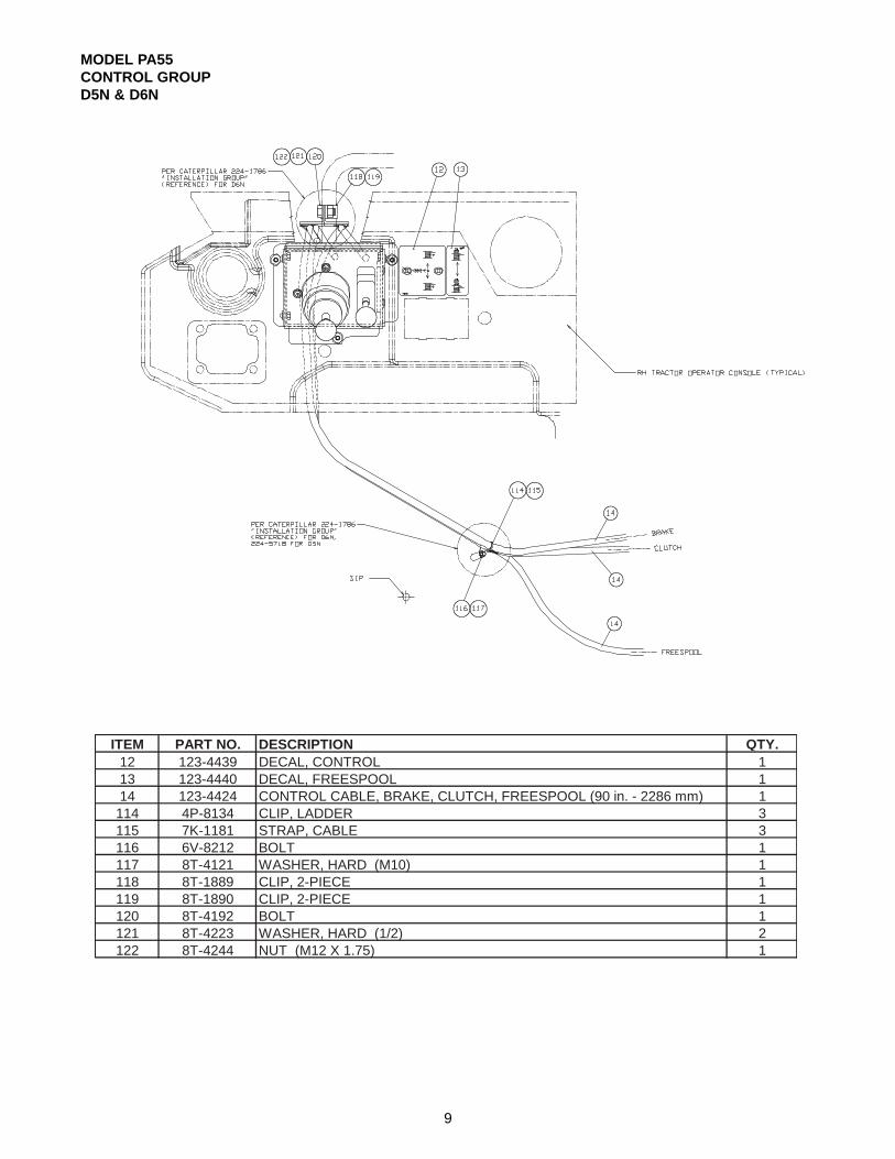
MODEL PA55CONTROL GROUPD5N & D6N
ITEM PART NO. DESCRIPTION QTY.12 123-4439 DECAL, CONTROL 113 123-4440 DECAL, FREESPOOL 114 123-4424 CONTROL CABLE, BRAKE, CLUTCH, FREESPOOL (90 in. - 2286 mm) 1114 4P-8134 CLIP, LADDER 3115 7K-1181 STRAP, CABLE 3116 6V-8212 BOLT 1117 8T-4121 WASHER, HARD (M10) 1118 8T-1889 CLIP, 2-PIECE 1119 8T-1890 CLIP, 2-PIECE 1120 8T-4192 BOLT 1121 8T-4223 WASHER, HARD (1/2) 2122 8T-4244 NUT (M12 X 1.75) 1
9

10
MODEL PA55CONTROL GROUP
D5N & D6N
FREESPOOL CONTROL
DUAL AXIS CONTROL

11
QTY.ITEM PART NO. DESCRIPTION W/FREESPOOL
28 104015 BOOT, FS CURRENT W/HOLD DOWN LIP + 132 7R-5874 KNOB 233 6V-8185 NUT (1/4-20) 634 8T-9368 CAPSCREW, HEX HEAD (1/4-20 x 2-1/4 G8 Z) 635 126-2821 SLIDING LOCKSCREW 236 126-2822 CABLE BUSHING 237 126-2823 CABLE SUPPORT HOUSING, OUTER 138 126-2824 CABLE SUPPORT HOUSING, INNER 139 126-2818 CABLE ANCHOR, OUTER 140 126-2820 CABLE ANCHOR, INNER 141 8T-4205 WASHER, FLAT-THIN (1/4) 2043 163-3201 BOOT 144 163-3198 BRAKE-OFF DETENT KIT * 1e 104020 CABLE HARDWARE KIT + 1h 3E-9860 LOCKNUT (5/16) 1
+ PACCAR Winch Division part number. Caterpillar part number not available at time of printing.
(Items a, b, c, d, f, g and j are not serviced separately)
*Note: Early design, prior to S/N 9900511, replaced by poppet-type detent kit 163-3198. Kit replacesearly design spring clip design with poppet-type detent mechanism for better retention in BRAKE-OFF position. Kit includes boot, spring, restrictor plate, poppet latch, jam nut screws and washers. Control lever shaft NOT included in kit and NOT available separately.
MODEL PA55CONTROL GROUPD5N & D6N

MODEL PA55CONTROL GROUP
D5N & D6N
12
CONTROL INSTALLATION INSTRUCTION
NOTE: These instructions are provided as a generalguide. Tractor options, application requirements or localregulations may require deviation from these recom-mendations.1. Install the gasket (9) to the bottom of the control
bracket (3).2. Install the control bracket onto the right hand con-
sole using existing button head capscrews andwashers (10, 11).
3. Carefully route control cables from winch to under-side of right hand console.
4. Route the control cables up through the opening ofthe control bracket and install cables into controllersas follows.
NOTE: For best results, replace the existing right-handplastic console cover with console cover assembly 167-1464 that is intended specifically for winch tractors.
Power Shift Control – Dual Axis1. Remove the six through-bolts, item 34, from the con-
trol stand and separate the two cable support hous-ings, items 37 & 38. From each plunger, remove thesliding lockscrew and threaded bushing, items 35 &36.
2. Install the sliding lock screw, item 35, onto the con-trol cables. Apply two drops of Loctite 242 to thecable threads and install the threaded bushing, item36, onto the cable core until the end of the cablecore is level with the end of the bushing.
3. Hold the controller in your left hand with the knobend up and the mounting bolts located at 6, 9 and 12o’clock positions. Mark the plunger closest to the 6o’clock position as the “clutch” control. Mark theplunger closest to the 12 o’clock position as the“brake” control. The “clipped” corner of the controlwill be installed toward the rear of the tractor.
4. Install the brake cable to the “brake” control plungerand the clutch cable into “clutch” control plunger.Move the control lever to extend the plungers farenough to expose the wrench flats. With a wrench,hold the plunger as you tighten the sliding lock screwto 50 lb·ft (68 Nm) torque.
5. Install the cable support housings, items 37 & 38,onto the controller. Place the groove of the controlcable housings into the saddle of the cable anchors,items 39 & 40. Install the six through-bolts, washers,lockwashers and nuts, items 31, 33, 34 & 41. Evenlytighten the bolts to 85 lb in (10 Nm) torque.
6. Insert the controller/cables sub-assembly from thebottom into the opening of the control bracket cover,item 4, and secure with three button, socket-headcapscrews, washers and nuts, items 5, 6 & 7. If thewinch is equipped with freespool, install thefreespool controller/cable sub-assembly at this time.If not equipped with freespool, install the controlbracket cover/controllers sub-assembly onto thecontrol bracket using three button, socket-head cap-screws, and washers, items 5 and 41.
Avoid routing cables near moving shafts or linkagewhich may cause damage to cables or restrict freemovement of tractor components.
CAUTION
Tightening the sliding lock screw without holdingthe plunger with a wrench will result in damage tothe control assembly.
CAUTION
TOP VIEW OF WINCH

MODEL PA55CONTROL GROUPD5N & D6N
13
Freespool Control Lever1. Remove the knob, item 32, and two capscrews and
nuts (f) from the long lever housing cover andremove the cover. The cable hardware kit (e) isfound in a small bag under the cover.
2. Prepare the control cable for installation byinstalling the o-ring over the control lever end of thecable. The control lever end is identified by the u-bolt groove in the cable housing.
3. Install one nut onto the cable core followed by thelockwasher.
4. Install the clevis and one more nut onto the cable.The cable core end must extend beyond the nut by7/32 in. (5.5 mm). Tighten the first nut to secure theclevis in this position.
5. Slip the clevis over the bellcrank of the lever andinstall the clevis pin and secure in place with cotterpins.
6. Place the cable clamp block into position to engagethe groove on the control cable housing.
7. Position the o-ring on the control cable housing sothat when the cable is lowered into place, the o-ringfits in the groove in the housing.
8. Install the two capscrews through the housing.Install the cover and nuts. Tighten the nuts to 90 lbin (10 Nm) torque.
9. Remove the two through-bolts and nuts from thetop two mounting holes of the lever housing.
10. Secure the lever to the control bracket with cap-screws, washers and nuts, items 6, 7 and 8. Thelong cover of the lever housing must face towardthe operator.
11. Install the control bracket cover/controller sub-assembly onto the control bracket base using threebutton, socket-head capscrews and washers, items5 and 7. Install the knob, item 32, onto the lever.
General Instructions1. Install the control instruction self-adhesive decal(s),
items 12 and 13, onto the console cover to the rearof the control bracket.
2. Fill winch to proper level with recommended oil.Refer to oil specifications found in the Operationand Preventive Maintenance Manual.
3. Verify proper control cable and operating pressureadjustment by following the procedures found in theOperation and Preventive Maintenance Manual orthe Service Manual.

THIS PAGE INTENTIONALLY LEFT BLANK
14

MODEL PA55BEVEL GEAR GROUPD5N & D6N(S/N 0704589 AND BELOW)
ITEM PART NO. DESCRIPTION QTY.1 119-2141 BEARING ASSEMBLY 12 119-1617 BEARING LOCKNUT 13 5P-2228 CAPSCREW, HEX HEAD (1/2 - 13 x 1) 64 119-1618 BEARING LOCKWASHER 15 118-5804 O-RING 16 123-4403 DOWEL PIN 17 119-2157 RETAINING RING 18 120-7638 OIL SEAL 19 118-8381 SEAL SPACER SLEAVE 110 118-6589 PUMP DRIVE PINION 111 118-5854 SHIM GASKET 112 118-7222 BEVEL PINION CARRIER 113 118-5855 SHIM .005 in. (.13 mm) 2-AR14 118-5856 SHIM .007 in. (.18 mm) 2-AR15 118-5857 SHIM .020 in. (.51 mm) 2-AR
118-6971 BEVEL PINION - 18T STANDARD SPEED - 3 SHAFT 1119-0536 BEVEL PINION - 14T SLOW SPEED - 4 SHAFT 1119-2218 BEVEL GEAR SET - 18/38T STD. SPD. - 2 BVL. GRS. 1 BVL. PN 1119-2219 BEVEL GEAR SET - 14/39T SLO. SPD. - 2 BVL. GRS. 1 BVL. PN 1
18 9X-7545 O-RING 119 1L-3768 RETAINING RING 120 119-2190 PLUG, BEVEL PINION 1
16
17
15
16
212120201919
1717
1212 1313 1414 15151616
9
1010
8
7
6
1
5 1111 3 4 2
SEE NOTE 2SEE NOTE 2SEE NOTE 6SEE NOTE 6
SEE NOTE 4SEE NOTE 4
SEE NOTE 5SEE NOTE 5
SEE NOTE 7SEE NOTE 7 SEE NOTE 4SEE NOTE 4
SEE NOTE 3SEE NOTE 3 SEE NOTE 1SEE NOTE 1
F
F/2
D/3
D
MODEL PA55BEVEL GEAR GROUP
D5N & D6N(S/N 0704590 AND UP)
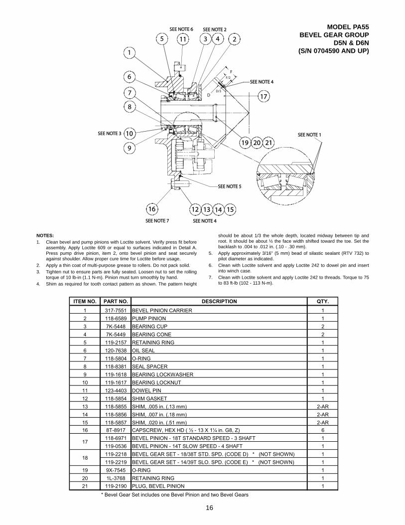
NOTES:1. Clean bevel and pump pinions with Loctite solvent. Verify press fit before
assembly. Apply Loctite 609 or equal to surfaces indicated in Detail A.Press pump drive pinion, item 2, onto bevel pinion and seat securelyagainst shoulder. Allow proper cure time for Loctite before usage.
2. Apply a thin coat of multi-purpose grease to rollers. Do not pack solid.3. Tighten nut to ensure parts are fully seated. Loosen nut to set the rolling
torque of 10 lb-in (1.1 N-m). Pinion must turn smoothly by hand.4. Shim as required for tooth contact pattern as shown. The pattern height
should be about 1/3 the whole depth, located midway between tip androot. It should be about ½ the face width shifted toward the toe. Set thebacklash to .004 to .012 in. (.10 - .30 mm).
5. Apply approximately 3/16” (5 mm) bead of silastic sealant (RTV 732) topilot diameter as indicated.
6. Clean with Loctite solvent and apply Loctite 242 to dowel pin and insertinto winch case.
7. Clean with Loctite solvent and apply Loctite 242 to threads. Torque to 75to 83 ft-lb (102 - 113 N-m).
ITEM NO. PART NO. DESCRIPTION QTY.
1 317-7551 BEVEL PINION CARRIER 12 118-6589 PUMP PINION 13 7K-5448 BEARING CUP 24 7K-5449 BEARING CONE 25 119-2157 RETAINING RING 16 120-7638 OIL SEAL 17 118-5804 O-RING 18 118-8381 SEAL SPACER 19 119-1618 BEARING LOCKWASHER 110 119-1617 BEARING LOCKNUT 111 123-4403 DOWEL PIN 112 118-5854 SHIM GASKET 113 118-5855 SHIM, .005 in. (.13 mm) 2-AR14 118-5856 SHIM, .007 in. (.18 mm) 2-AR15 118-5857 SHIM, .020 in. (.51 mm) 2-AR16 8T-8917 CAPSCREW, HEX HD ( ½ - 13 X 1¼ in. G8, Z) 6
118-6971 BEVEL PINION - 18T STANDARD SPEED - 3 SHAFT 1119-0536 BEVEL PINION - 14T SLOW SPEED - 4 SHAFT 1119-2218 BEVEL GEAR SET - 18/38T STD. SPD. (CODE D) * (NOT SHOWN) 1119-2219 BEVEL GEAR SET - 14/39T SLO. SPD. (CODE E) * (NOT SHOWN) 1
19 9X-7545 O-RING 120 1L-3768 RETAINING RING 121 119-2190 PLUG, BEVEL PINION 1
* Bevel Gear Set includes one Bevel Pinion and two Bevel Gears
17
18

WINCH CASE AND COVERS
SUCTION
STRAINER
1
2
3
A
A
VIEW A-A
24
20
11
10
29
15
14
24
3
73
2828
18
1
3
2
17
8
9
2
30
6
23
4
27
16 21 22 4
1
26
17
18
12
51
19
25
3
3
ALSO REFER TO CONTROL CABLE GUARD GROUP
1 - 8 UNC LIFTING EYE HOLE (2 PLACES)
STANDARDPTO
NOTES:
APPLY “FEL-PRO C648F” TO BOLTS TO PREVENTTHREAD CORROSION.
TIGHTEN FASTENERS TO 75 LB•FT (10.4 Kg•M)TORQUE.
APPLY “RTV 732” SILASTIC SEALANT TO BOTHSIDES OF GASKETS (11, 15 & 18) AND DRIVESCREWS (2).
TIGHTEN HEX NUT (22) UNTIL LOCKWASHER (21)IS FLATTENED AND THEN TURN ONE FLAT.
1
2
3
4
17

WINCH CASE AND COVERS
ITEM PART NO. DESCRIPTION QTY.1 5P-2228 CAPSCREW, HEX HEAD (1/2-13 X 1) 122 7H-4543 DRIVE SCREW 43 5P-9436 PLUG, DRAIN (MAY BE SUBSTITUTED FOR ITEM 7) 14 5P-1403 PLUG, OIL FILL (INCLUDES ITEM 27) 15 6L-9965 O-RING 26 5F-5434 VENT PLUG 17 118-5783 SIGHT GAUGE (INCLUDES ITEM 28) 18 118-6973 WINCH CASE - STANDARD PTO 110 118-6598 COVER, TOP ACCESS 111 118-6316 GASKET 112 120-7541 STRAINER COVER 114 118-6588 COVER, SIDE ACCESS 115 120-7543 GASKET 116 118-6298 TIE BOLT 117 118-6597 COVER, LOWER ACCESS 218 118-6317 GASKET 219 118-8382 DRAW BAR PIN 120 118-6314 SPACER TUBE 121 119-1623 LOCKWASHER (1 3/4) 122 2B-2673 NUT, HEX HEAD (1 3/4 NC) 123 3B-8822 ELBOW 224 6K-7917 CAPSCREW, HEX HEAD (1/2-13 X 1) SS* 1525 3B-5320 COTTER PIN (3/8 X 3 IN.) 226 119-2165 EXPANSION PLUG - 3 SHAFT ONLY 127 6V-5065 O-RING - FOR OIL FILL PLUG 128 9X-4609 O-RING - FOR OIL DRAIN & LEVEL PLUG/SIGHT GAUGE 229 2B-7457 PLUG (3/8 NPT SQ HD) 1
*SS = SELF-SEALING MATERIAL PREAPPLIED TO THREADS
18

CLUTCH SHAFT GROUP
*
*
* Refer to tractor specific installation and parts manual.
19

CLUTCH SHAFT GROUP
ITEM PART NO. DESCRIPTION QTY.1 6V-5065 O-RING (PART OF ITEM 14) 22 009-3691 BEARING CUP 13 119-2138 BALL BEARING 24 119-2140 BEARING CUP 15 120-7635 BEARING CONE 16 119-2206 NEEDLE BEARING - INNER RACE 47 124-0493 THRUST BEARING 28 119-2208 NEEDLE BEARING 49 009-3690 BEARING CONE 110 5P-2228 CAPSCREW, HEX HEAD (1/2 - 13 X 1) 611 7X-0326 CAPSCREW, HEX HEAD (1/2 - 13 X 3) 6
118-7225 CLUTCH SHAFT - 4 SHAFT 1118-7217 CLUTCH SHAFT - 3 SHAFT 1
13 120-7633 THRUST BEARING RACE 414 5P-1403 PLUG (CONTAINS ITEM 1) 215 148-8407 PLUG, -6 ORB HEX 116 8M-4437 O-RING 817 120-7629 O-RING 218 119-1590 O-RING 219 119-1549 O-RING 420 119-1616 RETAINING RING 221 2D-6398 RETAINING RING 222 119-2171 BEARING RETAINER 223 119-1550 BACK-UP RING 424 147-2728 ROTARY SEAL SHAFT 225 118-5817 THRUST BEARING SPACER 226 119-1628 BACK-UP WASHER 227 119-2193 ROTARY SEAL 2
118-6582 PINION GEAR - 18 TEETH - 4 SHAFT 1118-6560 PINION GEAR - 15 TEETH - 3 SHAFT 1
29 118-6568 BRAKE HUB 130 118-5858 BEVEL GEAR SPACER 231 118-5844 BEARING CARRIER 2
PINION SPACER - 4 SHAFT 2PINION SPACER - 3 SHAFT 1
33 118-5848 SHIM SET 1118-6647 SHIM, .005 in. (.13 mm) 2-AR118-6599 SHIM, .007 in. (.18 mm) 2-AR118-6600 SHIM, .020 in. (.51 mm) 2-AR118-6951 CLUTCH SHAFT BEARING CARRIER - 4 SHAFT 1118-6969 CLUTCH SHAFT BEARING CARRIER - 3 SHAFT 1
36 118-5864 BRAKE HUB SPACER 138 4H-1440 ROLLPIN 239 120-7663 SLEEVE 440 140-1197 ORIFICE PLUG 2
34
AR = AS REQUIRED
118-5864
12
28
32
35
20
CLUTCH ASSEMBLY
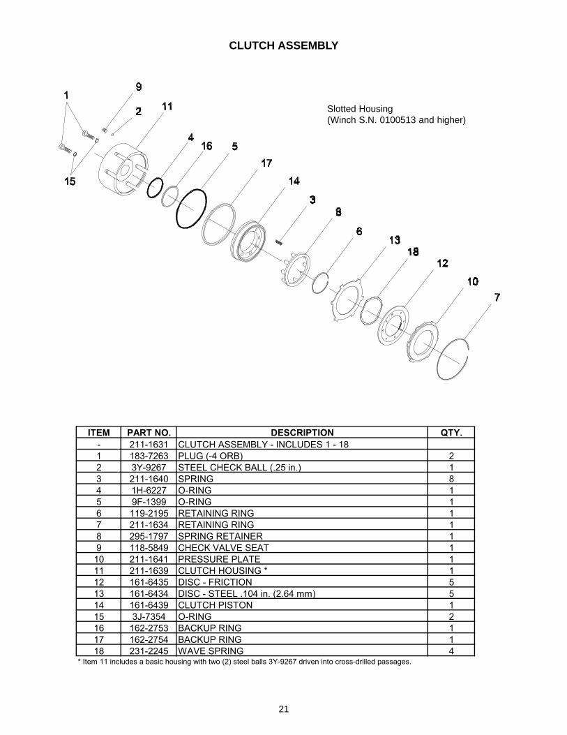
ITEM PART NO. DESCRIPTION QTY.- 211-1631 CLUTCH ASSEMBLY - INCLUDES 1 - 181 183-7263 PLUG (-4 ORB) 22 3Y-9267 STEEL CHECK BALL (.25 in.) 13 211-1640 SPRING 84 1H-6227 O-RING 15 9F-1399 O-RING 16 119-2195 RETAINING RING 17 211-1634 RETAINING RING 18 295-1797 SPRING RETAINER 19 118-5849 CHECK VALVE SEAT 110 211-1641 PRESSURE PLATE 111 211-1639 CLUTCH HOUSING * 112 161-6435 DISC - FRICTION 513 161-6434 DISC - STEEL .104 in. (2.64 mm) 514 161-6439 CLUTCH PISTON 115 3J-7354 O-RING 216 162-2753 BACKUP RING 117 162-2754 BACKUP RING 118 231-2245 WAVE SPRING 4
* Item 11 includes a basic housing with two (2) steel balls 3Y-9267 driven into cross-drilled passages.
Slotted Housing(Winch S.N. 0100513 and higher)
21

ITEM PART NO. DESCRIPTION QTY.- 211-1630 BRAKE ASSEMBLY, STD - INCLUDES 1 - 201 009-3691 BEARING CUP 12 4L-6454 CAPSCREW, HEX HEAD (3/8 - 16 X 1 GD 8 Z) 23 148-8407 PLUG, HEX SOCKET (-6 ORB) 34 119-1577 O-RING 35 5F-3144 O-RING 16 3Y-9267 STEEL BALL (PRESSED INTO HOUSING) 17 119-1586 O-RING 18 123-4415 RETAINING RING 19 211-1638 PRESSURE PLATE 110 211-1634 RETAINING RING 111 211-1632 PRESSURE PLATE 112 1S-6119 O-RING 113 211-1633 BRAKE PISTON 114 211-1637 BRAKE HOUSING - CURRENT (REQUIRES 1 OF ITEM 6) 115 161-6435 DISC - FRICTION - BRONZE 816 161-6434 DISC - STEEL - .104 in. (2.64 mm) 817 211-1636 BRAKE CARRIER 118 119-2167 BRAKE SPRING 2
BRAKE ASSEMBLY
Slotted Housing(Winch S.N. 0100878 and higher)
22

CABLE DRUM GROUP
23
INSTALL GEAR, ITEM 12, WITH GROOVETOWARD OUTSIDE
REFER TO IDLERSHAFT GROUP

CABLE DRUM GROUP
24
ITEM PART NO. DESCRIPTION QTY.1 8M-2031 BALL BEARING 12 4F-2041 BEARING CUP 23 5P-3236 BEARING CONE 24 6K-7917 CAPSCREW, HEX HEAD (1/2 - 13 X 1 G5 SS) 125 8T-8917 CAPSCREW, HEX HEAD (1/2 - 13 X 1 1/4 G5) 116 1S-6119 O-RING 27 123-4416 RETAINING RING, EXTERNAL 28 7M-2275 RETAINING RING, INTERNAL 19 118-5866 OIL SEAL 210 119-0561 CAPSCREW, SOCKET HEAD (1/2 - 13 X 1 G8 SS) 111 118-7229 CABLE DRUM 112 118-7215 SECOND REDUCTION GEAR 113 118-6583 SECOND REDUCTION GEAR SHAFT 114 118-6968 BEARING CARRIER, COVER 115 118-6975 BEARING CARRIER, DRUM 116 118-5847 SHIM SET (2 pair each, .005, .007, .020 in. (.13, .18, .51 mm) 2
118-6273 FERRULE - 3/4 IN. (19 mm) WIRE ROPE 1118-6275 FERRULE - 7/8 IN. (22 mm) WIRE ROPE 1118-6276 FERRULE - 1 IN. (25 mm) WIRE ROPE 1
18 ----- NO GASKET, USE DOW RTV 732 OR EQUIVALENT --19 138-2400 VALVE MOUNTING PLATE 1
SS - SELF SEALING
17

IDLER SHAFT GROUPWITH FREESPOOL
ITEM PART NO. DESCRIPTION QTY1 119-0160 BEARING ASSEMBLY - INNER 12 114-5870 BEARING ASSEMBLY - OUTER 13 119-1547 O-RING 14 118-5859 LOCK PLATE 15 8T-9383 CAPSCREW, HEX HEAD (1/2 - 13 - 3/4 G5) 26 8T-8917 CAPSCREW, HEX HEAD (1/2 - 13 - 1 1/4 G5) 27 124-0764 CAPSCREW, HEX HEAD (1/2 - 13 X 2 G5) 28 038-7338 PLUG, SOCKET HEAD 19 120-7633 THRUST WASHER 110 118-6535 ADJUSTER 111 119-2170 BUSHING 112 118-6584 PINION, SECOND REDUCTION 113 118-7224 GEAR, FIRST REDUCTION 114 118-6917 CARRIER, IDLER SHAFT 115 039-2676 SHOULDER SCREW 116 9L-7469 COTTER PIN 217 119-1626 BALL PLUNGER 218 1B-4430 JAM NUT 219 2J-5038 ROD END 220 3K-9042 RETAINING RING 221 119-2184 SHIFT RAIL, INCLUDES ITEM 33 122 118-6567 YOKE 123 1D-5120 JAM NUT 124 118-5862 SHIFT COLLAR 125 118-6658 CABLE CONNECTOR 126 118-5785 BELLCRANK WELDMENT 127 4L-6454 CAPSCREW, HEX HEAD (3/8 - 16 X 1 G8) 228 8T-4223 WASHER (1/2) 129 118-6585 COLLAR 130 119-2210 PIN 131 5H-8853 O-RING 132 119-2209 CONTROL CABLE ADJUSTER 133 119-0570 NYLON PELLET 134 3B-4506 LOCKWASHER (3/8) 2
25
REFER TO CONTROLGROUP FOR CABLES

FOURTH SHAFT GROUP
ITEM PART NO. DESCRIPTION QTY.1 119-2173 ROLLER BEARING 22 119-1572 THRUST WASHER - .062 in. (1.58 mm) 13 118-6651 CLUSTER GEAR 37/17 TEETH 14 8M-4986 O-RING 25 118-6297 SPACER 16 118-6533 COUNTERSHAFT PIN 17 118-6287 THRUST WASHER - .217 in. (5.5 mm) 1
26
GAUGE GROUP
12
3
45
6 7 8
ITEM PART NO. DESCRIPTION QTY1 123-4412 PRESSURE GAUGE KIT (INCLUDES ALL ITEMS BELOW) 12 118-6319 PRESSURE GAUGE 13 118-6596 BRACKET 14 061-7921 ADAPTER (1/4 INCH TO -4) 15 030-7961 UNION (45 DEGREE, -4) 16 6V-8918 CAPSCREW, HEX HEAD (5/16 - 18 x 1-1/4 G5) 27 3B-4506 WASHER (5/16) 28 119-2131 NUT, HEX (5/16) 29 118-6271 HOSE ASSEMBLY (-4 JIC FEMALE SWIVEL, 96 INCHES) 110 3J-7352 ADAPTER (-4 TO JIC) 1

PUMP GROUP
27
QTY.ITEM PART NO. DESCRIPTION STD PTO
1 118-6979 PUMP ASSEMBLY 12 123-4411 ELBOW, 45o -8, PRESSURE SIDE 1
3B-7731 STREET ELBOW, 45o SUCTION ---031-6303 ELBOW, 45o SUCTION 1
4 1H-9779 BARBED HOSE ADAPTER ---5 3B-4504 LOCKWASHER (1/4) 46 7X-0264 CAPSCREW, HEX HEAD (1/4 - 20 X 1 1/2 G8) 27 7X-0266 CAPSCREW, HEX HEAD (1/4 - 20 X 3 G8) 2
3
CAUTIONWARNING! !! DANGER - 2,000 LB (900 KG) SPRING PRELOAD !
USE PRESS FOR DISASSEMBLY PER SERVICE INSTRUCTIONS.SEVERE PERSONAL INJURY OR DEATH MAY RESULT IF ROD
GUIDE REMOVAL IS ATTEMPTED WITHOUT A PRESS
VENT HOLE
.
231485679
ACCUMULATOR ASSEMBLY - 118-7012
ITEM PART NO. DESCRIPTION QTY1 NSS ROD 12 096-8139 RETAINING RING 13 NSS ROD GUIDE 14 NSS SPRING 15 NSS PISTON 16 119-0554 CAST IRON PISTON RING 17 SEAL (PACCAR P/N 107956) 18 NSS BARREL ASSEMBLY 19 NUT (PACCAR P/N 22702) 1- 123-4413 SEAL KIT (CONTAINS 2, 6 & 7)
NSS = Not Serviced Separately
3/4 - 16, -8 O-RINGBOSS PORT
REFER TO BEVELPINION GROUP

HYDRAULIC CONTROL GROUP - STANDARD PTO
28
A2827 3822
A B
B
49
16
43
53
60
14
66
64
65 5 4
2
54
51
50
48 52
61 62
IN CASE THREADS ONLY
COVER
35
34
35
37
38
36
2722
11
22
7
VIEW BB
VIEW AA

HYDRAULIC CONTROL GROUP - STANDARD PTO
29
ITEM PART NO. DESCRIPTION QTY.1 1D-5120 NUT, JAM (3/4 - 10) 22 118-6318 FILTER BRACKET 13 030-7943 ELBOW - 45° - 8 ORB/-8JIC PORT C1,C2,T 34 118-6321 FILTER HEAD 15 118-6322 FILTER ELEMENT 16 8L-6557 ADAPTER - 1/8 NPT / - 8 17 061-9463 ADAPTER - 1/4 NPT / -8 48 7J-4026 ELBOW - 90° - 4 ORB/-4JIC PORT L,G 29 030-7948 ELBOW - 90° - 8 ORB/-8JIC, PORT P 1
10 1P-7625 ELBOW - 90° - 8 ORB/-10JIC, ACCUMULATOR 111 8M-0547 ELBOW - 90° - 8 JIC UNION 312 119-0131 YOKE 213 5H-8853 O-RING 214 9M-7958 CLAMP 115 118-7012 ACCUMULATOR 116 119-2164 STRAINER 117 119-0156 CLEVIS PIN 218 3K-9042 RETAINING RING 419 118-6332 HOSE, 17 in. (432 mm) VALVE TO GAUGE PORT 120 119-0115 HOSE, 24 in. (610 mm) VALVE TO T, CR 221 119-0118 HOSE, 17 in. (432 mm) VALVE TO B 122 119-0120 HOSE, 50 in. (1,270 mm) VALVE TO CL 123 8T-4223 LOCKWASHER (1/2) 224 118-6313 ACCUMULATOR CLAMP BRACKET 125 104003 * CONTROL VALVE ASSEMBLY 126 158-6530 QUICK DISCONNECT, GAUGE PORT 127 118-6301 SUCTION HOSE 128 118-6265 CONNECTOR 129 105055 * HOSE - VALVE TO ACCUMULATOR 130 119-2209 ADJUSTER 231 6F-0612 NUT, HEX (1/4 - 28) 232 6M-7476 ELBOW 45° - 10 ORB/-10 JIC PORT A 33 119-0157 HITCH PIN 2
ITEM PART NO. DESCRIPTION QTY.34 138-2409 LUBE TUBE 135 119-0161 CLAMP 236 118-6270 CLAMP 137 3J-7355 UNION - 4 138 119-0122 HOSE, LUBE 139 100796 * ADAPTER, -16 ORB /-8 JIC 140 030-7963 UNION - 45°, -8/-8 141 138-2438 ELBOW 90°, -16 ORB/-8 JIC 142 127-7025 SLEEVE, GAUGE PORT 143 119-1535 SPRING, SUCTION STRAINER 1
45 118-6308 ACCUMULATOR MOUNTING ANGLE 146 119-0549 STUD (1/2 - 13 X 2 3/4) 248 119-1520 STUD (1/2 - 13 X 2 1/4) 149 118-6283 STRAINER SHIELD 150 3J-4818 LOCKWASHER (1/2) 151 3H-3680 NUT, JAM (1/2 - 13) 152 6V-8188 NUT (1/2 - 13) 553 118-6284 SEAL RING .25 in. (6.4 mm) THICK 154 5M-6214 PLUG, 1/8 NPT 155 118-6654 UPPER SUCTION TUBE 156 9S-7739 UNION 157 118-6653 LOWER SUCTION TUBE 158 8T-9043 CAPSCREW, HEX HD (5/16 - 18 X 7/8 GD 8 Z) 259 3B-4505 LOCKWASHER (5/16) 260 118-6286 SEAL RING .06 in. (1.5 mm) THICK 1-261 5M-3062 CAPSCREW, HEX HD (3/8 - 16 X 3/4 GD 8 Z) 262 3B-4506 LOCKWASHER (3/8) 263 3B-8822 ELBOW, 90° 1/8 NPT 164 100843 * COVER 165 138-2407 CAPSCREW, BUTTON HEAD (#10-24 X 5/8, SS) + 366 8M-4986 O-RING 1
* PACCAR Winch Division part number. Caterpillar part number was not available at time of printing.
+ SS - Self Sealing
44 119-0118 HOSE - 17 in. (432 mm) PUMP TO FILTER, FILTER TO VALVE 2

CONTROL VALVE ASSEMBLY
30
ITEM PART NO. DESCRIPTION QTY1 119-1522 CLUTCH CONTROL VALVE CARTRIDGE (CLV) 1
119-2129 SEAL KIT FOR ITEM 1 12 119-1523 BRAKE CONTROL VALVE CARTRIDGE (BRV) 1
119-2127 SEAL KIT FOR ITEM 2 13 119-1525 SHUTTLE VALVE (S1, S2) 2
119-1631 SEAL KIT FOR ITEM 3 24 40166 * DIFFERENTIAL PRESSURE UNLOADING CARTRIDGE (PU) 1
125-3325 SEAL KIT FOR ITEM 4 15 105094 * ORIFICE DISC .095 16 8M-0505 ADAPTER -8 ORB -8 JIC - BRAKE PORT 17 105629 * RELIEF VALVE CARTRIDGE (RV) 1
63616 * SEAL KIT FOR ITEM 7 18 105631 * CHECK VALVE (CV) 1
63617 * SEAL KIT FOR ITEM 8 19 105630 * LOGIC CONTROL CARTRIDGE (LC) 1 63618 * SEAL KIT FOR ITEM 9 1
* PACCAR part numbers shown; no Catapillar part numbers available at this time.

FAIRLEAD ASSEMBLY
3 ROLLER 4 ROLLER118-7211 3 ROLLER FAIRLEAD ASSEMBLY118-7213 4 ROLLER FAIRLEAD ASSEMBLY
1 118-6935 FAIRLEAD FRAME 1 12 118-6649 ROLLER - VERTICAL 2 23 119-2174 BEARING CONE 6 84 3K-3963 BEARING CUP 6 85 118-5803 DUST GUARD ASSEMBLY 6 86 119-2186 GREASE RETAINER 4 47 124-0763 ROLLER - HORIZONTAL 1 28 118-6648 SHAFT - VERTICAL 2 29 118-6604 SHAFT - HORIZONTAL 1 210 119-2211 WASHER 3 411 5M-6667 LOCK NUT 3 412 8T-9383 CAPSCREW, HEX HEAD (1/2 - 13 X 3/4) 3 413 3B-8489 GREASE FITTING 5 616 120-7634 WASHER - .030 in. (.8 mm) 5 617 118-6298 TIE BOLT 1 118 119-1623 LOCK WASHER (1 3/4) 1 119 2B-2673 NUT, HEX (1 3/4 - 5) 1 120 123-4410 SHIM - .125 in. (3.18 mm) 6-AR 6-AR21 120-7536 SPACER 3 4
1 -
AR - AS REQUIRED
4th ROLLER KIT (CONTAINS ONE EACH 7, 9, 10, 11, 12, 13, 21 AND TWO EACH 3, 4 & 5)174-4770
ITEM PART NO. DESCRIPTION QUANTITY
31
1
16
1
1
3
2
43
NOTES:
WHILE TURNING ROLLER, TIGHTEN NUT. WHEN ROLLER WILL NO LONGER TURN, BACK OFF NUT 1/8 TURN.
SHIM BOTH SIDES AS REQUIRED TO REDUCE END PLAY TO LESS THAN O.030 in. (0.8 mm).
TIGHTEN NUT TO 200 - 300 LB•FT (271 - 407 N•m) TORQUE.
WHEN INSTALLING FAIRLEAD ON WINCH IN FIELD, REMOVE ORIGINAL CABLE GUARD SPACER TUBE AND RE-USEUPPER TIE BOLT (118-6298), LOCKWASHER (119-1623) AND NUT (2B-2673).
THOROUGHLY PACK ALL FAIRLEAD BEARINGS WITH MULTI-PURPOSE GREASE ON ASSEMBLY.
2
3
4
1
Standard 3-roller fair-lead consists of twovertical rollers, andone horizontal rollerin the top position.
Four roller fairleadadds a second hori-zontal roller in thebottom position.
Vertical Rollers
Horizontal Roller(s)
View A-A
A
A

CONTROL CABLE GUARD GROUP
32
NOTE:If this guard is field installed, be sure toremove and discard the four (4) 1 inch longcapscrews in the top cover, and replace themwith the four (4) 1-1/4 inch capscrews shownbelow (item 2).
ITEM PART NO. DESCRIPTION QTY.1 138-9294 CABLE GUARD 12 138-9291 CAPSCREW, HEX HEAD (1/2 -13 X 1 1/4 SS*) 43 5P-2228 CAPSCREW, HEX HEAD (1/2 -13 X 1) 34 8M-4791 WASHER, HARDENED (1/2) 7
*SS - SELF SEALING MATERIAL PREAPPLIED TO THREADS


![OLD CARCO LLC (SDNY) - 36 - FIRST REPLY MEMORANDUM OF LAW in Opposition re: 35[RECAP] MOTION for Compensation](https://img.pdfslide.us/doc/110x75/577d27a01a28ab4e1ea463aa/old-carco-llc-sdny-36-first-reply-memorandum-of-law-in-opposition-re.jpg)