Embed Size (px)
Citation preview

Sentinel Power Systems
WWW.SENTINELPOWERSYSTEMS.COM
Don’t get left in the dark
Installation and Operations ManualSGT-160 Residential Solar Kit
WWW.SENTINELPOWERSYSTEMS.COM

Sentinel Power Systems
WWW.SENTINELPOWERSYSTEMS.COM
Don’t get left in the dark
Sentinel Power Systems was formed with a single goal in mind, to make renewable energy easy to understand, install and use. Since its inception, the company has striven for perfection in its product development and system design in order to offer the absolute best to its customers and installers.
For the last couple of decades the technology in the renewable energy industry has been perfecting itself, and yet has managed to evade mainstream acceptance. Sentinel Power Systems has bridged the gap between the state of the art technology and the requirement for ease of use and comprehension. Sentinels complete line of integrated packages is the milestone that installers and end users have been waiting for. Whether the interest is in Solar, Wind or Emergency Power, everything is included in our comprehensive packages.
The future health of our planet and our families depends on our ability to do the right thing and to make the right choices. These choices will have lasting impacts for generations to come. Sentinel Power Systems is committed to bringing the technology we need to the doorsteps of everyone willing to do their part.
The simplest changes in our daily lives make big differences, installing renewable energy is a positive and lasting legacy to leave our Earth and our children.
Adam WebbPresident Sentinel Power Systems
About our Company
Page 2 Sentinel Power Systems-SGT160 install Guide Release 1

Sentinel Power Systems
WWW.SENTINELPOWERSYSTEMS.COM
Don’t get left in the dark
Contact Information Sentinel Power Systems180 Trowers Road, Unit #18Woodbridge, OntarioCanada, L4L 8A6t.905-850-6601f.905-850-6603e.info@sentinelpowersystems.comwww.sentinelpowersystems.com
Document Revision History
Page 3 Sentinel Power Systems-SGT160 install Guide Release 1
Version Date Comments 1.0 01/16/08 Released

Sentinel Power Systems
WWW.SENTINELPOWERSYSTEMS.COM
Don’t get left in the dark
Table of Contents
Document Revision History .....................................................................................................3
Table of Contents .....................................................................................................................4
IMPORTANT SAFETY INSTRUCTIONS ..................................................................................5
1 Introduction – The SGT-160 Solar Kit system ......................................................................6
2 Installation Instructions .........................................................................................................9Step 1 - The Mounting System...........................................................................................9Step 2 - The Inverter .........................................................................................................10 Step 3 - Connecting the Enphase Micro-Inverter Wiring Harnesses ............................11Step 4 - System Grounding ..............................................................................................12Step 5 - Enphase Installation Map and Connecting the PV Modules ..........................12Step 6 - The PV Panel........................................................................................................14
3 Commissioning ....................................................................................................................14
4 Operating Instructions ........................................................................................................15
5 Troubleshooting ..................................................................................................................15General Micro-Inverter Error Reporting ..........................................................................15Troubleshooting Suggestions for inoperable Micro-Inverters ......................................15 Disconnecting the Enphase Micro-Inverter from the PV Module .................................15
6 Technical Data .....................................................................................................................16M175-24-240-S Micro-Inverter Operating Parameters ..................................................17Voltage and Frequency Limits for Utility Interaction .....................................................18The SGT-160 Solar Kit........................................................................................................19
7 Appendix .............................................................................................................................20 Limited Warranty on PV Panel and Bracket.....................................................................20Limted Warranty on Enphase Inverter..............................................................................21 Quick Installation Guide ...................................................................................................22 Enphase Installation Maps ...............................................................................................27Notes..................................................................................................................................29
Page 4 Sentinel Power Systems-SGT160 install Guide Release 1
Sentinel Power Systems
WWW.SENTINELPOWERSYSTEMS.COM
Don’t get left in the dark
IMPORTANT SAFETY INSTRUCTIONS
SAVE THESE INSTRUCTIONS This manual contains important instructions that shall be followed during installation and maintenance of the SGT-160 Residential Solar Kit
To reduce the risk of electrical shock, and to ensure the safe installation and operation of the SGT-160, the following safety symbols have been placed throughout this document to indicate dangerous conditions and important safety instruction.
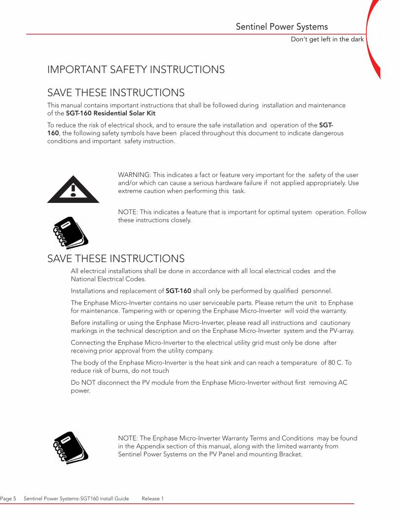
WARNING: This indicates a fact or feature very important for the safety of the user and/or which can cause a serious hardware failure if not applied appropriately. Use extreme caution when performing this task.
NOTE: This indicates a feature that is important for optimal system operation. Follow these instructions closely.
SAVE THESE INSTRUCTIONS All electrical installations shall be done in accordance with all local electrical codes and the National Electrical Codes.
Installations and replacement of SGT-160 shall only be performed by qualified personnel.
The Enphase Micro-Inverter contains no user serviceable parts. Please return the unit to Enphase for maintenance. Tampering with or opening the Enphase Micro-Inverter will void the warranty.
Before installing or using the Enphase Micro-Inverter, please read all instructions and cautionary markings in the technical description and on the Enphase Micro-Inverter system and the PV-array.
Connecting the Enphase Micro-Inverter to the electrical utility grid must only be done after receiving prior approval from the utility company.
The body of the Enphase Micro-Inverter is the heat sink and can reach a temperature of 80 C. To reduce risk of burns, do not touch
Do NOT disconnect the PV module from the Enphase Micro-Inverter without first removing AC power.
NOTE: The Enphase Micro-Inverter Warranty Terms and Conditions may be found in the Appendix section of this manual, along with the limited warranty from Sentinel Power Systems on the PV Panel and mounting Bracket.
Page 5 Sentinel Power Systems-SGT160 install Guide Release 1

Sentinel Power Systems
WWW.SENTINELPOWERSYSTEMS.COM
Don’t get left in the dark
Introducing the SGT-160 Residential Solar Kit:
The SGT-160 comes with everything you need to start generating your own energy: the solar panel, mounting system, and grid tied power inverter. The system is completely plug and play, and specially designed for easy expansion. All you need is a 240 VAC power cable to be connected to the first SGT-160, and everything after that simply plugs in.
The future health of our planet and families depend on your ability to do the right thing and to make the right choices. The Sentinel SGT-160 Residential Solar Kit will help your family reduce its carbon footprint on the planet, and also lower your monthly utility bill. Grid tied solar systems are the easiest renewable energy system to install, own and maintain. They have no moving parts, no regular service requirements and make no noise.
Grid tied solar systems connect to the home using standard house wiring. They are designed to harness energy from the sun and convert that energy into useable electricity. When enough power is being generated from your solar system, no electricity will flow in from the utility company. Anytime your system is generating more power than you are using, the excess will flow back into the grid, turning your meter backwards.
Introducing the custom designed mounting hardware:
The Sentinel photovoltaic (PV) solar panel mounting system is a custom top-down roof mounting solution designed and manufactured with the home owner in mind. This innovative design incorporates designed lightweight aluminum components and all stainless steel hardware to allow for maximum quality and installation efficiency. The lightweight nature of the aluminum rail utilizes the basic laws of physics to create structural competence rather than just bulking up the rail in height adding unnecessary and costly aluminum and install time.
The Sentinel rail system uses stainless steel nuts inserted directly into the aluminum rails to simplify the assembly process and to maximize installation efficiency. The rail system is also designed to connect together for easy expansion, allowing a single panel installation to grow over time without having to change mounting systems.
•Easy to setup and install
•Modular design
•Install one, the rest just plug in
•Up to 16 modules in one string
• Mounts bolt together
•Wires into a 2 pole 15 Amp breaker
•25 Year Warranty on Solar Module
•Made in Canada
Page 6 Sentinel Power Systems-SGT160 install Guide Release 1

Sentinel Power Systems
WWW.SENTINELPOWERSYSTEMS.COM
Don’t get left in the dark
Introducing Enphase Micro Inverter:
The Enphase Micro-Inverter system is the world’s most technologically advanced inverter system for use in utility interactive applications. This manual details the safe installation and operation of the Enphase Micro-Inverter.
The three key elements of an Enphase Micro-Inverter System are: 1) the Enphase Micro-Inverter, 2) the Energy Management Unit (Emu), and 3) the Enlighten web based analytics and visualization. All three elements are highly integrated to provide a comprehensive energy production and management system.
The Enphase Micro-Inverter System maximizes energy production from your photovoltaic array. Each Enphase Micro-Inverter is individually connected to each PV module in your array. This unique configuration means that an individual Maximum Peak Power Point Tracker (MPPT) controls each PV module. This insures that the maximum power available from each PV module is exported to the utility grid regardless of the performance of the rest of the PV modules in the array which may be affected by shading, soiling, orientation, module mismatch, etc. The result is maximum energy production from the total PV system.
Micro-Inverter systems are inherently more reliable than centralized or string inverters. The distributed nature of the Micro-Inverter System insures that there is no single point of failure in the PV system. Enphase Micro-Inverters are designed to operate at full power at temperatures as high as 65 C (150 F). The inverter housing is designed for outdoor installation and complies to the NEMA6 environmental enclosure rating standard:
NEMA6 rating definition: Indoor or outdoor use primarily to provide a degree of protection against hose-directed water, and the entry of water during occasional temporary submersion at a limited depth and damage from external ice formation.
Solar systems using Enphase Micro-Inverters are extremely simple to design and install. There are no string calculations needed. Individual PV modules may be installed in any combination of module quantity, type, age and orientation. There are no cumbersome centralized or string inverters to install. Each Micro-Inverter quickly mounts on the PV racking, directly beneath each PV module. Low voltage DC wires connect from the PV module directly to the co-located Micro-Inverter, eliminating the risk of personnel exposure to lethal 600Vdc power. The Energy Management Unit (Emu) communications gateway is installed by simply plugging it into any convenient 120Vac wall socket. The full network of Enphase Micro-Inverters will automatically begin reporting to the Enphase Enlighten web server. The Enlighten analytics software lets you know not only the immediate and historical system performance trends, but also informs you when the PV system is not performing as expected.
These are just a few of the advantages of the Enphase Micro-Inverter System that will provide tremendous time, material and cost savings, while maximizing energy production from your PV system and providing better ROI on your solar investment.
Page 7 Sentinel Power Systems-SGT160 install Guide Release 1

Sentinel Power Systems
WWW.SENTINELPOWERSYSTEMS.COM
Don’t get left in the dark
Introducing photovoltaic module(PV):
The 160 watt PV module is a perfect combination of high quality components and advanced technology. The superior quality of the modules is based upon the scientific knowledge, experience, and the utilization of the high quality materials for the assembly obtained from the worlds leading suppliers. Features - 72 high-efficiency monocrystalline silicon solar cells in series
- Cells are laminated between sheets of EVA-based encapsulant material and high- transmissivity low-iron 4mm tempered glass
- Corrosion-resistant anodized aluminum frame meets the requirements of certifying agencies
- The junction box has terminal connection block and provides splash proof IP-rated housing. It is equipped with by-pass dides providing “ hot spot “ protection for the solar cells.
- Module Warranty : 25-year limited warranty of 80% output; 12-year limited warranty of 90% power output.
Page 8 Sentinel Power Systems-SGT160 install Guide Release 1

Sentinel Power Systems
WWW.SENTINELPOWERSYSTEMS.COM
Don’t get left in the dark
2 Installation Instructions - The Mounting Sytem
WARNING: Before installing the SGT-160, read all instructions and cautionary markings in the user manual.
WARNING: All electrical installations shall be done in accordance with all local electrical codes and the National Electrical Codes.
WARNING: Make sure the proper tools are used during the installation.
The mounting system for the SGT 160 has been designed for ultimate ease of installation, here are the basic steps to get you started.
STEP 1Connect the mounting feet to the module support rail, do this using the 1/4” x 3/4” stainless
steel hardware provided. Do the bolts up finger tight at this point as you may have to adjust the feet slightly when on the roof. For single panel installations use all four feet provided, and when installing multiple panels you can use one mounting foot to join two modules support rails together. It is recommended to always have the mounting feet positioned so that they can be used to join panel rails together, this will save time and holes in the roof when expanding the system.
STEP 2Fasten the mounting feet to the roof using the hardware provided, or with a suitable lag screw or
bolt. Ensure the module mounting rails are between 28 and 34 inches apart, this will ensure that the module frame is supported in it’s strongest position.
NOTE:The clamping system consists of end clamps to attach the module frame to the roof track support rail. This design allows solar modules to be installed at a lower profile to the roof, providing a more aesthetically pleasing installation. Module clamps are specifically designed, extruded and engineered for each specific module frame. Our innovative clamping system provides inward tension on the module frame securing the laminate in the frame. Nuts are conviently welded to the backof the frame for easy installation.
Page 9 Sentinel Power Systems-SGT160 install Guide Release 1

Sentinel Power Systems
WWW.SENTINELPOWERSYSTEMS.COM
Don’t get left in the dark
2 Installation Instructions - The Inverter
WARNING: Before installing the Enphase Micro-Inverter, read all instructions and cautionary markings in the user manual and on the Enphase Micro-Inverter and the photovoltaic array.
WARNING: All electrical installations shall be done in accordance with all local electrical codes and the National Electrical Code (NEC), ANSI/NFPA 70.
WARNING: Connecting the Enphase Micro-Inverter to the electrical utility grid must be done only after receiving prior approval from the utility company.
WARNING: Only qualified personnel must connect the Enphase Micro- Inverter to the electrical utility grid.
WARNING: Risk of electric shock. Normally grounded conductors may be ungrounded and energized when a ground fault is indicated.
Installation of the Enphase Micro-Inverter System involves the following key steps:
1 Installing the AC branch circuit junction box
2 Attaching the Enphase Micro-Inverters to the racking
3 Connecting the Enphase Micro-Inverter wiring harnesses
4 System Grounding
5 Enphase Installation map and Connecting the PV modules
NOTE: It is recommended that all Micro-Inverters be installed and all system inter-wiring connections completed prior to installing the PV modules. Please refer to the Quick Install Guide at the end of this document for a diagram of the Enphase Micro-Inverter System. Each step of these installation instructions is numerically referenced in the Quick Install Guide drawing.
WARNING: DO NOT connect Enphase Micro-Inverters to the utility grid or energize the AC circuit(s) until after completing Step 5 of these installation instructions.
Page 10 Sentinel Power Systems-SGT160 install Guide Release 1

Sentinel Power Systems
WWW.SENTINELPOWERSYSTEMS.COM
Don’t get left in the dark
Step 1 - Install the AC Branch Circuit Junction Box Mount the AC junction box so when the installation is complete it will be located under the edge of the first module in the string cable into the junction box using an appropriate gland or strain relief fitting.
Route the continuous Grounding Electrode Conductor (GEC) through the AC branch circuit junction box. Check local code requirements for the gauge of the GEC.
WARNING: Use electrical system components approved for wet locations only.
NOTE: Please refer to the Enphase website for a list of approved PV module racking systems.
NOTE: The Enphase M175-24-240-S Micro Inverter is designed to operate with most 72-cell PV module configurations; sometimes referred to as “24V modules”.
Step 2 - Attach the Enphase Micro-Inverters to the Racking Start with the inverter that is connected to the junction box that was just installed. The Sentinel mounting system has been designed specifically for the Enphase inverter and has two Stainless steel inserts centered in the rail for quick and accurate mounting. The inverter can be mounted on the top or bottom rail.Mount one Micro-Inverter at each of these locations using hardware supplied in the kit.
WARNING: Allow a minimum of 1” spacing between the top of the roof and the bottom of the Micro-Inverter. Enphase also recommends 1” of spacing between the back of the PV module and the top of the inverter.
Step 3 - Connecting the Enphase Micro-Inverter Wiring Harnesses Each Micro-Inverter has been provided with two, 36-inch long AC wire harnesses with multi-pin connectors (the DC input wires are approximately 6 inches long and are terminated with single pole MC connectors). The AC connectors are oppositely sexed, so that multiple inverters can be connected together to form one continuous AC branch circuit.
Plug the AC connector of one Micro-Inverter into the connector of the next Micro-Inverter to form a continuous AC branch circuit. Please
Page 11 Sentinel Power Systems-SGT160 install Guide Release 1

Sentinel Power Systems
WWW.SENTINELPOWERSYSTEMS.COM
Don’t get left in the dark
check the Micro-Inverter rating label for the maximum allowable number of Micro-Inverters on one AC branch circuit.
Install a protective end cap (included in the Enphase Installation Kit) on the open AC connector of the last Micro-Inverter in the AC branch circuit.
WARNING: Do NOT exceed the maximum number of Micro-Inverters in an AC branch circuit, as displayed on the unit-rating label. Each Micro-Inverter AC branch circuit must be sourced from a dedicated branch circuit protected by a 15A maximum breaker.
WARNING: Unused AC Micro-Inverter wire harness connectors may be live when the system is energized by the utility system. Make sure protective end caps have been installed on all unused AC connectors.
NOTE: Be sure to size the AC wire gauge to account for voltage drop between the AC branch circuit junction box and the point of utility inter-connection.
Step 4 - System Grounding Each Enphase Micro-Inverter has been provided with a ground clip that can accommodate a 6-10 AWG conductor.
Route a continuous Grounding Electrode Conductor through each of the Micro-Inverters and AC branch circuit junction box to the NEC approved AC grounding electrode.
Note: The AC output neutral is not bonded to ground inside the Micro- Inverter.
Step 5 - Enphase Installation Map and Connecting the PV Modules The Enphase Installation Map is designed to be a diagrammatic representation of the physical location of each Enphase Micro-Inverter in your PV installation. This information will be used by Enphase to provide you with detailed information about the performance of your PV system and graphically visualize your PV system on the Enphase Enlighten website. A simple rectangular matrix has been included in the Appendix of this manual for your use. Feel free to provide your own matrix layout if a larger or more intricate installation map is required.
Each Enphase Micro-Inverter has two removable labels located on the top cover. Peel one of the labels from each Enphase Micro-inverter and affix it to the respective location on the Enphase installation map.
Send the installation map to Enphase after completion. Enphase prefers to receive a digital copy of the installation map via an upload
Page 12 Sentinel Power Systems-SGT160 install Guide Release 1

Sentinel Power Systems
WWW.SENTINELPOWERSYSTEMS.COM
Don’t get left in the dark
to the Enlighten web site during installation set up or via email. If digital scanning of the map is not possible, please provide the map via fax or mail. See the contact information at the beginning of this manual for a fax number, email address, and mailing address. It is recommended that you make a copy of the installation map if you will be sending in the original.
Enphase will create a graphical representation of your PV system on the Enlighten website. The Enlighten web server will provide you with detailed information regarding the performance of your PV system (please go to www.enphaseenergy.com for more information on the Enphase Enlighten communication, visualization and analytics system).
Installation maps and examples can be downloaded from www.enphaseenergy.com. An example may also be found in the Appendix section of this manual.
Finally, mount the PV modules above their corresponding Micro-Inverters. Each Micro-Inverter has been provided with two oppositely sexed Multi-Contact DC plus and minus connectors.
First connect the positive DC wire from the PV module to the positive DC connector (female socket) of the Micro-Inverter. Then connect the negative DC wire from the PV module to the negative DC connector (male socket) of the Micro-Inverter. Repeat for all modules, Micro-Inverters
Page 13 Sentinel Power Systems-SGT160 install Guide Release 1

Sentinel Power Systems
WWW.SENTINELPOWERSYSTEMS.COM
Don’t get left in the dark
2 Installation Instructions - The PV Panel
WARNING: Before installing the SGT-160, read all instructions and cautionary markings in the user manual.
WARNING: All electrical installations shall be done in accordance with all local electrical codes and the National Electrical Codes.
WARNING: Make sure the proper tools are used during the installation.
Before mounting the solar panels to the mounting frame, make sure you attach the ground lug provided to the frame. You can now connect the ground wire to the ground lug.
Once the module has been grounded, you can now install the panel onto the mounting rail. Use the Aluminum Clamps provided in the kit to secure the panel in place, do not tighten the clamps until all 4 have been installed and you are sure of the module position.
Repeat this proceedure for every additional module.
Page 14 Sentinel Power Systems-SGT160 install Guide Release 1
3 Commissioning
WARNING: Connecting the Enphase Micro-Inverter to the electrical utility grid must only be done after receiving prior approval from the utility company.
WARNING: Only qualified personnel must connect the Enphase Micro- Inverter to the electrical utility grid.
WARNING: Ensure that all AC and DC wiring is correct. Ensure that none of the AC and DC wires are pinched or damaged. Ensure that all junction boxes are properly closed.
Note: Each Micro-Inverter will beep six times to indicate normal start-up operation once AC or DC power is applied.
Follow these procedures to commission the Enphase Micro-Inverter PV system: 1 Turn ON the AC disconnect on each Micro-Inverter AC branch circuit
junction box.

Sentinel Power Systems
WWW.SENTINELPOWERSYSTEMS.COM
Don’t get left in the dark
2 Turn ON the main utility-grid AC circuit breaker.
3 Your system will start producing power after a five-minute wait time.
4 Operation and production can be verified by reading the display on the LCD panel of the Energy management unit (Emu) communications gateway.
5 Please refer to the Emu User Manual for information on installation and operation of the Emu.
4 Operating Instructions When the Enphase Micro-Inverter is powered on, you will hear six beeps indicat-ing proper start–up
In the event of a GFDI failure, you will hear a 5-minute long continuous tone when the fault occurs. This will repeat when AC and DC power are cycled to the Micro-Inverter.
Proper operation of the Enphase Micro-Inverters can be verified via the Emu.
5 Troubleshooting Adhere to all the safety measures described throughout this manual. Enphase recommends the following troubleshooting steps in the event your PV system does not operate correctly:
WARNING: The Enphase Micro-Inverter contains no user serviceable parts. Please return the unit to Enphase for maintenance.
General Micro-Inverter Error Reporting Normal Operation: Listen for six short beeps when AC or DC power is first applied to the Micro-Inverter. This indicates normal Micro-Inverter operation.
GFDI Fault: A long constant tone after AC and DC power has been cycled, indicates the Micro-Inverter has detected a ground fault (GFDI) error. This tone will sound for 5 minutes, after which the Micro-Inverter will remain silent. The fault will continue to be reported by the EMU. The error can only be cleared via the Emu after the ground fault condition has been remedied.
Other Faults: All other faults are reported to the Emu. Please refer to this manual for a list of additional faults and troubleshooting procedures.
WARNING: Troubleshooting of the PV array or Micro-Inverter system should be done by qualified personnel only.
Page 15 Sentinel Power Systems-SGT160 install Guide Release 1

Sentinel Power Systems
WWW.SENTINELPOWERSYSTEMS.COM
Don’t get left in the dark
WARNING: Never disconnect the DC wire connectors under load. Ensure that no current is flowing in the DC wires prior to disconnecting.
WARNING: Always disconnect AC power before disconnecting the PV module wires from the Enphase Micro-Inverter.
WARNING: The Enphase Micro-Inverters are powered both by AC power from the utility grid and DC power from the PV modules. Make sure you disconnect both the AC and the DC connections and reconnect either AC or DC power to hear the six start-up beeps.
Troubleshooting Suggestions for inoperable Micro-Inverters Check the connection to the utility grid. Verify the utility voltage and frequency are within allowable ranges shown in the Technical Data section of this manual. Verify utility power is present at the inverter in question by removing AC, then DC power. Never disconnect the DC wires while the Micro-Inverter is producing power. Re-connect the AC power conductor and listen for 6 short beeps.
Check the AC branch circuit interconnection harness between all the Micro-Inverters. Verify each inverter is energized by the utility grid with the previous procedure.
Check the DC connections between the Micro-Inverter and the PV module.
Verify the PV module DC voltage is within the allowable range shown in the Technical Data section of this manual.
Make sure that all the AC switches in the junction boxes are functioning properly and are closed.
If the problem persists, please call customer support at Enphase Energy.
Disconnecting the Enphase Micro-Inverter from the PV Module To insure the Micro-Inverter is not disconnected from the PV modules under load, adhere to the following procedure in the order shown:
1 Turn off the AC disconnect on the AC branch circuit junction box.
2 Turn off the utility-grid AC circuit breaker.
3 Disconnect the AC branch circuit wire harness connector(s).
4 Using a DC current probe, verify there is no current flowing in the DC wires between the PV module and the Micro-Inverter.
5 If there is measurable DC current, cover the PV module connected to the Micro-Inverter with an opaque material.
6 Disconnect the PV module DC wire connectors from the Micro-Inverter.
7 Remove the Micro-Inverter from the PV array racking.
Page 16 Sentinel Power Systems-SGT160 install Guide Release 1

Sentinel Power Systems
WWW.SENTINELPOWERSYSTEMS.COM
Don’t get left in the dark
6 Technical Data - Micro Inverter
WARNING: It is required to match the DC operating voltage range of the PV module with the allowable input voltage range of the Enphase Micro-Inverter.
WARNING: The maximum open circuit voltage of the PV module may not exceed the specified maximum input voltage of the Enphase Micro-Inverter.
The Enphase M175-24-240-S Micro-Inverter has been specifically optimized for operation with most 72-cell (24V nominal) PV module configurations. Be sure to verify the voltage and current specifications of your PV module match with those of the Micro-Inverter.
The output voltage and current of the PV module depends on the quantity, size and temperature of the PV cells, as well as the solar insolation on each cell. The highest PV module output voltage occurs when the temperature of the cells is the lowest and the module is at open circuit (not operating). The maximum short circuit current rating of the module must be equal to or less than the maximum input DC short circuit current rating of the Micro-Inverter.
Page 12 Copyright Enphase Energy Inc. 2008 Release 1.4
M175-24-240-S Micro-Inverter Operating Parameters
Topic Unit Min Typical Max
DC Operating Parameters
MPPT voltage range V 25 32 40
Maximum DC input voltage V 54
Maximum DC input short circuit current
A 10
Maximum DC input current A 8
Ground fault protection mA 1000
AC Operating Parameters
Maximum AC output Power (at 65 deg. C)
W 175
Output power factor 0.85 0.99 1
Nominal AC output voltage range Vrms 211 240 264
Extended AC output voltage range Vrms 206 240 269
Maximum AC output current mA 750 830
Nominal AC output frequency range Hz 59.3 60 60.5
Extended AC output frequency range Hz 59.2 60 60.6
Maximum AC output over current protection
A 15
Page 17 Sentinel Power Systems-SGT160 install Guide Release 1

Sentinel Power Systems
WWW.SENTINELPOWERSYSTEMS.COM
Don’t get left in the dark
Page 18 Sentinel Power Systems-SGT160 install Guide Release 1
M175-24-240-S Micro-Inverter Operating Parameters
Topic Unit Min Typical Max
and duration AC Voltage trip limit accuracy % 2.5 Frequency trip limit accuracy Hz ±0.1 Trip time accuracy ms ±33
Miscellaneous Operating Parameters
Maximum inverters per AC branch circuit
1 16
Peak inverter efficiency % 95.0
CEC weighted efficiency % 94.5
Nominal MPP tracking efficiency % 99.6
Total Harmonic Distortion % 2.5 5
Operating temperature range C -25 65
Night Tare Loss mW 580
Storage temperature range C -25 65
Weight Lbs < 4.0
Features
Dimensions (approximate) 11” x 5 _” x 1 _”
Enclosure environmental rating NEMA6
Cooling Convective – no fan
Communication Powerline
Standard warranty term 10 years
Voltage and Frequency Limits for Utility Interaction
Condition
Simulated utility source Maximum time (sec) (cycles) at
60 Hz before cessation of
current to the simulated utility
Voltage (V) Frequency (Hz)
A < 0.50 V Typical Rated 0.16
B 0.50 VTypical V < 0.88
VTypical Rated 2
C 1.10 VTypical< V < 1.20
VTypical Rated 1
D 1.20 VTypical V Rated 0.16
E Rated f > 60.5 0.16
F Rated f < (59.8 – 57.0) 0.16 – 300
G Rated f < 57.0 0.16

Sentinel Power Systems
WWW.SENTINELPOWERSYSTEMS.COM
Don’t get left in the dark
KitSpecifications
Length 64in / 162.6cm
Width 32in / 81.3cmDepth 4.5in / 11.4cmWeight 40lbs / 18.8kgs
Solar ModuleMaximum Power Output
160 watts
Nominal Voltage 32 VDCApproval cULWarranty on Solar Module
25 Years
Panel MountMaterial AluminumHardware Self Sealing AnchorsType Flush Roof MountExpandable Design Up to 16 ModulesWarranty 10 Years
6 Technical Data - SGT160 Solar Kit
Page 19 Sentinel Power Systems-SGT160 install Guide Release 1

Sentinel Power Systems
WWW.SENTINELPOWERSYSTEMS.COM
Don’t get left in the dark
Warranty StatementBy buying products from Sentinel Power Systems, you have purchased a standard of quality which fulfils the highest requirements. As a sign of our trust in this quality, we are pleased to be able to offer you a extended warranty of service as stipulated by the provisions below.
1a Product warrantySentinel Power Systems warrants that solar modules (hereinafter: products) produced by it are free from defects in material and workmanship. Should a defect be determined within a period of two years from the date of purchase, Sentinel Power Systems shall upon its own discretion repair or replace the product or reimburse the customer to the amount of the purchase price.
1b ServiceThe solar power modules which you have purchased have power specificationswith regard to the power yield to be achieved (the so-called rated value) within a certain tolerance range. Please see the specification sheet enclosed with your product for the respective rated value.We assume that the rated value for the power yield of our products will decrease to a minor degree only over a period of 25 years.If the actual power yield falls below the rated value by more than 9 % in the first 10 years calculated from the date of purchase and after that by more than 19 % till the end of service period (25 years) for reasons caused exclusively by our product despite correct operation and this deficiency is proven by an acknowledged test institute/test method,we will supply replacement products which provide a power yield according to the rated value mentioned above or take measures to make possible such a power yield or refund the proportional age value (taking account of conducted depreciation) of your module (for anactual power yield of 70 % of the lower tolerance value,we would thereforerefund 11 % of the age value of your module in the latter alternative) accordingto our own option. If replacement products are supplied,we will not be obligedto provide new or comparable products. Sentinel Power Systems is entitled to supply used and/or repaired products as replacements.
2. Assertion of ClaimsThe assertion of claims for the services stipulated under section 1 presupposesthat the customer has (i) informed the authorized reseller/distributor of ourproducts in writing of the alleged claim,or that (ii) this written notification hasbeen sent directly to the address stated in section 5 in the event that the notifiablereseller/distributor no longer exists (e.g. due to discontinuance of businessor bankruptcy). Any such assertion of claims must be accompanied bythe original sales receipt as the proof of purchase and time of purchase of the Sentinel Power Systems product(s). The assertion of the claim must occur within 14 daysfrom the date that the claim is identified. The return of products may onlyoccur after the written consent of Sentinel Power Systems has been given.
3. Appropriate employmentThe service stipulated in Sections 1.a and 1.b can also only be rendered,if ourproducts are employed and/or operated correctly. Therefore our services mustbe withheld,if the descent of the power outputfalls below the minimum outputlevels mentioned in clause 1 and the output descent is not caused exclusivelyby our products themselves. This is the case by e.g.
a Customer’s or installer’s defaults regarding the allowance of the productinstructions for installation,oper ation and maintenance.
b Substitution,r epare or modification of products by persons not authorized by Sentinel Power Systems.
c Improper use of products such as but not limited to,the use of products for construction purposes and functions,e .g. protection against water,wind and/or noise.
d Vandalism,destruc tion by external influences and/or persons/animals.
e Force majeure,e .g. flooding,fir e,e xplosions,r ock fall,dir ect or indirect stroke of lighting or other extreme weather conditions as e.g. hail,hurricanes ,sandstorms or any other conditions beyond Sentinel Power Systems influence and power.
4. Exclusion of LiabilityThis service certificate in no way constitutes a guarantee with regard to anoutput of 91 % or 81 % in relation to the rated value and is merely a voluntaryadditional service on the part of Sentinel Power Systems. Consequently, Sentinel Power Systems is only obliged to provide the services stipulated in section 1 in the event that the actual output falls short of the rated value. Any claims for liability that go beyond this,par ticularly claims concerning thecompensation of damages that have not arisen from our own products,onwhatever legal grounds,ar e hereby excluded.This does not apply in the event of personal injuries or damages to privately used objects sustained in accordance with the product liability laws. Furthermore,it does not apply in cases of wrongful intent,gross negligence,the absence of guaranteed properties and the violation ofmaterial contractual obligations,or in cases where it is otherwise mandatory established under existing law.
5. Your contact personIf you wish to claim the service stipulated in Section 1,please consultCustomer ServiceSentinel Power Systems180 Trowers Road #18Woodbridge, OntarioPhone: (905-850-6601)Fax: (905-850-6603)[email protected]
6. Applicable lawAll services and warranties stipulated according to this certificate shall begoverned and construed in accordance with the substantial laws of Canada without regard to the conflict of Law principles.
7. ValidityThe table below contains all current types of module to which this guarantee applies. Module types not contained in this list are not subject to this guarantee.
Adam WebbPresidentSentinel Power Systems
7 Appendix - Limited Warranty on PV Panel and Mounting Bracket
Page 20 Sentinel Power Systems-SGT160 install Guide Release 1

Sentinel Power Systems
WWW.SENTINELPOWERSYSTEMS.COM
Don’t get left in the dark
7 Appendix - Limited Warranty on EnPahse InverterEnphase Energy Inc. (“Enphase”) has developed a highly reliable Micro-Inverter that is designed to withstand normal operating conditions when used for its originally intended purpose in compliance with the Enphase User Manual supplied with the originally shipped system. The Enphase limited warranty (“Limited Warranty”) covers defects in workmanship and materials of the Enphase Micro-Inverter (“Defective Product”) for a period of ten (10) years from the date of original purchase of such Micro-Inverter at point of sale to the original end user customer (the “Warranty Period”).
During the Warranty Period, Enphase will, at its option, repair or replace the Defective Product free of charge, provided that Enphase through inspection establishes the existence of a defect that is covered by the Limited Warranty. Enphase will, at its option, use new and/or reconditioned parts in repairing or replacing the Defective Product. Enphase reserves the right to use parts or products of original or improved design in the repair or replacement of Defective Product. If Enphase repairs or replaces a Defective Product, the Limited Warranty continues on the repaired or replacement product for the remainder of the original Warranty Period or ninety (90) days from the date of Enphase’s return shipment of the repaired or replacement product, whichever is later.
The Limited Warranty covers both parts and labor necessary to repair the Defective Product, but does not include labor costs related to un-installing the Defective Product or re-installing the repaired or replacement product. The Limited Warranty also covers the costs of shipping repaired or replacement product from Enphase, via a non-expedited freight carrier selected by Enphase, to locations within the United States (including Alaska and Hawaii) and Canada, but not to other locations outside the United States or Canada. The Limited Warranty does not cover, and Enphase will not be responsible for, shipping damage or damage caused by mishandling by the freight carrier and any such damage is the responsibility of the freight carrier.
To obtain repair or replacement service under this Limited Warranty, the customer must comply with the following policy and procedure:
All Defective Product must be returned with a Return Merchandise Authorization Number (RMA) which customer must request from Enphase. Before requesting the RMA, however, the customer should contact an Enphase technical support representative to evaluate and troubleshoot the problem while the Enphase Micro-Inverter is in the field, since many problems can be solved in the field.
If in-field troubleshooting does not solve the problem, Customer may request the RMA number, which request must include the following information:
Proof-of-purchase of the Defective Product in the form of (1) the dated purchase receipt from the original purchase of the product at point of sale to the end user, or (2) the dated dealer invoice or purchase receipt showing original equipment manufacturer (OEM) status, or (3) the dated invoice or purchase receipt showing the product exchanged under warranty Model number of the Defective Product Serial number of the Defective Product Detailed description of the defect
Shipping address for return of the repaired or replacement product All Defective Product authorized for return must be returned in the original shipping container or other packaging that is equally protective of the product The returned Defective Product must not have been disassembled or modified without the prior written authorization of Enphase
Page 21 Sentinel Power Systems-SGT160 install Guide Release 1
Sentinel Power Systems
WWW.SENTINELPOWERSYSTEMS.COM
Don’t get left in the dark
The Limited Warranty does not cover normal wear and tear of Enphase Micro-Inverters or costs related to the removal, installation, or troubleshooting of the customer’s electrical systems. The Limited Warranty does not apply to, and Enphase will not be responsible for, any defect in or damage to any Enphase Micro-Inverter: (1) that has been misused, neglected, tampered with, altered, or otherwise damaged, either internally or externally; (2) that has been improperly installed, operated, handled or used, including use under conditions for which the product was not designed, use in an unsuitable environment, or use in a manner contrary to the Enphase User Manual or applicable laws or regulations; (3) that has been subjected to fire, water, generalized corrosion, biological infestations, acts of God, or input voltage that creates operating conditions beyond the maximum or minimum limits listed in the Enphase Micro-Inverter specifications, including high input voltage from generators or lightning strikes; (4) that has been subjected to incidental or consequential damage caused by defects of other components of the solar system; or (5) if the original identification markings (including trademark or serial number) of such Micro-Inverter have been defaced, altered, or removed. The Limited Warranty does not extend beyond the original cost of the Enphase Micro-Inverter.
THE LIMITED WARRANTY IS THE SOLE AND EXCLUSIVE WARRANTY GIVEN BY ENPHASE AND, WHERE PERMITTED BY LAW, IS MADE EXPRESSLY IN LIEU OF ALL OTHER WARRANTIES, EXPRESS OR IMPLIED, STATUTORY OR OTHERWISE, INCLUDING, WITHOUT LIMITATION, WARRANTIES OF TITLE, QUALITY, MERCHANTABILITY, FITNESS FOR A PARTICULAR PURPOSE OR NON-INFRINGEMENT OR WARRANTIES AS TO THE ACCURACY, SUFFICIENCY OR SUITABILITY OF ANY TECHNICAL OR OTHER INFORMATION PROVIDED IN MANUALS OR OTHER DOCUMENTATION. IN NO EVENT WILL ENPHASE BE LIABLE FOR ANY SPECIAL, DIRECT, INDIRECT, INCIDENTAL OR CONSEQUENTIAL DAMAGES, LOSSES, COSTS OR EXPENSES HOWEVER ARISING, WHETHER IN CONTRACT OR TORT, INCLUDING WITHOUT LIMITATION ANY ECONOMIC LOSSES OF ANY KIND, ANY LOSS OR DAM-AGE TO PROPERTY, OR ANY PERSONAL INJURY.
To the extent any implied warranties are required under applicable law to apply to the Enphase Micro-Inverter, such implied warranties shall be limited in duration to the War-ranty Period, to the extent permitted by applicable law. Some states and provinces do not allow limitations or exclusions on implied warranties or on the duration of an implied warranty or on the limitation or exclusion of incidental or consequential damages, so the above limitation(s) or exclusion(s) may not apply. This Limited Warranty gives the customer specific legal rights, and the customer may have other rights that may vary from state to state or province to province.
Page 22 Sentinel Power Systems-SGT160 install Guide Release 1
Sentinel Power Systems
WWW.SENTINELPOWERSYSTEMS.COM
Don’t get left in the dark
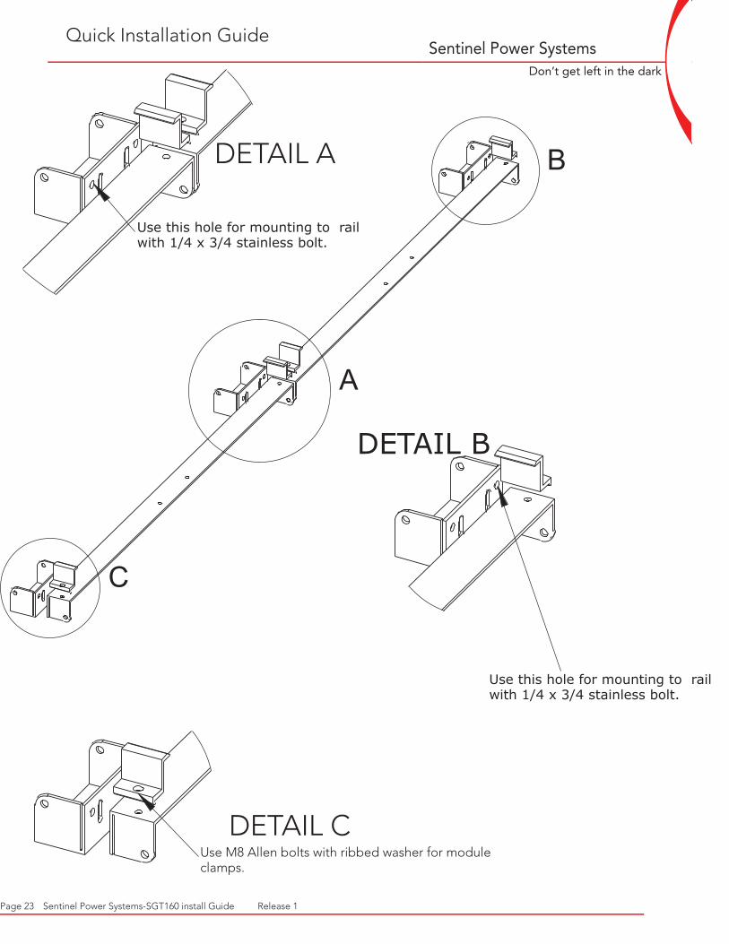
Use this hole for mounting to rail with 1/4 x 3/4 stainless bolt.
B
A
C
DETAIL B
Use this hole for mounting to rail with 1/4 x 3/4 stainless bolt.
DETAIL C Use M8 Allen bolts with ribbed washer for module clamps.
DETAIL A
Page 23 Sentinel Power Systems-SGT160 install Guide Release 1
Quick Installation Guide

Sentinel Power Systems
WWW.SENTINELPOWERSYSTEMS.COM
Don’t get left in the dark
A
B
DETAIL A
Foot orientation for future expansion. If no expansion is planned, use foot place-ment in detail “C”.
DETAIL B
Foot orientation for module rail joint.
DETAIL C
Foot orientation for fiirst module. Does not allow for addition of module rail as the foot will be under the module once com-pletely installed.
C
Quick Installation Guide
Page 24 Sentinel Power Systems-SGT160 install Guide Release 1

Sentinel Power Systems
WWW.SENTINELPOWERSYSTEMS.COM
Don’t get left in the dark
A
DETAIL A
Mount Enphase inverter to the upper most rail on the roof to allow water to flow away from it. Use the 1/4 x 3/4stainless steel bolts provided for bolting to the rail
Quick Installation Guide
Page 25 Sentinel Power Systems-SGT160 install Guide Release 1

Sentinel Power Systems
WWW.SENTINELPOWERSYSTEMS.COM
Don’t get left in the dark
Page 26 Sentinel Power Systems-SGT160 install Guide Release 1
Blank Installation Worksheet

Sentinel Power Systems
WWW.SENTINELPOWERSYSTEMS.COM
Don’t get left in the dark
SGT160 Installation Map
Page 27 Sentinel Power Systems-SGT160 install Guide Release 1

Sentinel Power Systems
WWW.SENTINELPOWERSYSTEMS.COM
Don’t get left in the dark
Page 28 Sentinel Power Systems-SGT160 install Guide Release 1
N
E
W
S 030827002851
030826002740
030825002660
030826002753
0308
2700
2873
0308
2600
2754
0308
2500
2705
FIX
ED
AR
RA
Y 20
d
egre
e til
t
0308
2700
2823
TRA
CK
ING
AR
RA
Y
EM
U #
D
UA
L A
XIS
WE
BB
RE
SID
EN
CE
8
X 1
65 W
att
mo
dul
es13
20 W
att t
otal
out
put p
oten
tial
SAM
PLE
INST
ALL
ATI
ON
MA
P -
CA
D L
AYO
UT

Sentinel Power Systems
WWW.SENTINELPOWERSYSTEMS.COM
Don’t get left in the dark
Notes
Page 29 Sentinel Power Systems-SGT160 install Guide Release 1