Embed Size (px)
Citation preview
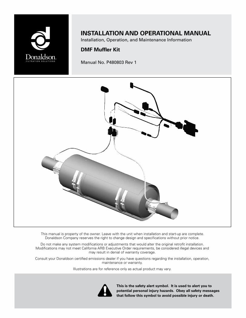
INSTALLATION AND OPERATIONAL MANUALInstallation, Operation, and Maintenance Information
DMF Muffler Kit Manual No. P480803 Rev 1
This is the safety alert symbol. It is used to alert you to potential personal injury hazards. Obey all safety messages that follow this symbol to avoid possible injury or death.
This manual is property of the owner. Leave with the unit when installation and start-up are complete. Donaldson Company reserves the right to change design and specifications without prior notice.
Do not make any system modifications or adjustments that would alter the original retrofit installation. Modifications may not meet California ARB Executive Order requirements, be considered illegal devices and
may result in denial of warranty coverage.
Consult your Donaldson certified emissions dealer if you have questions regarding the installation, operation, maintenance or warranty.
Illustrations are for reference only as actual product may vary.

2 Donaldson DMF Muffler Owners Manual - P480803 Rev 1
Donaldson DMF Muffler Owners Manual - P480803 Rev 1 3
DMF Mufflers are passive catalytic mufflers designed to reduce diesel PM and
gaseous emissions. This manual includes pre-installation requirements, installation
instructions, warranty activation procedures, and maintenance recommendations for
the Donaldson DMF Muffler.
Donaldson Retrofit Emissions System
DMF Muffler Application ......................4
DMF Muffler Kit Illustration ..................4
Introduction ...........................................5DMF Muffler Kit Contents ................................................5
Pre-Installation Requirements ..............5
DMF Muffler Pre-Installation ............................... 5Application Pre-Assessment .................................................... 5
Fuel Requirement ........................................................................ 6
Engine Lube Oil Requirement .................................................... 6
Mounting Hardware Requirement ........................................... 6
Weigh and Record Filter Section ............................................. 6
EDM Pre-Installation ............................................. 7
Installation .............................................7
Vertical Muffler Installation ................................. 8Remove the Existing Muffler ..................................................... 8
Install the DMF Muffler .............................................................. 8
Install the Heat Shield on Muffler Body .................................. 8
Attach DMF Muffler to Tubing .................................................. 9
Operate Vehicle & Check for Leaks ......................................... 9
Attach Engine Tags .................................................................... 9
Install the EDM ........................................................................... 9
Horizontal Muffler Installation ............................. 9Remove the Existing Muffler ..................................................... 9
Install the DMF Muffler .............................................................. 9
Install the Heat Shield on Muffler Body ................................ 10
Attach DMF Muffler to Tubing ................................................ 11
Operate Vehicle & Check for Leaks ....................................... 11
Attach Engine Tags .................................................................. 11
Install the EDM ......................................................................... 11
Installation Checklist ......................................................11
DMF Muffler ....................................................................11
Emissions Device Monitor (EDM) ................................11
Program Compliance .....................................................12
Contents
Activate the Warranty ..........................12http://pwww.donaldson.com ........................................12
Emissions Retrofit Documentation ..............................12
Operation .............................................12
Maintenance and Service ..................12DPF Section Service Records ......................................12
Routine Inspections During Vehicle Service .............13
Filter Cleaning . ...............................................................13
Filter Disposal Information ...........................................13
TroubleShooting ..............................................................14
DMF Muffler Kit Limited Warranty ......15
4 Donaldson DMF Muffler Owners Manual - P480803 Rev 1
Donaldson Retrofit Emissions System
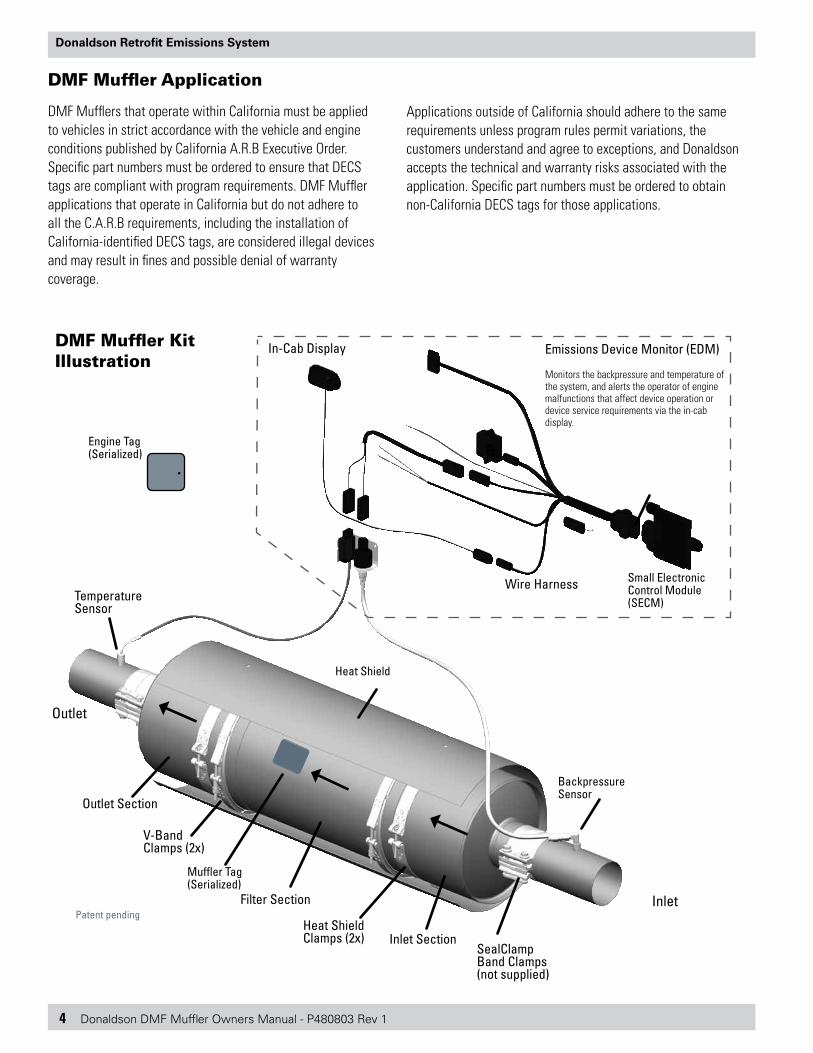
DMF Muffler Kit Illustration
Emissions Device Monitor (EDM)
Monitors the backpressure and temperature of the system, and alerts the operator of engine malfunctions that affect device operation or device service requirements via the in-cab display.
Engine Tag(Serialized)
Patent pending
Outlet
Inlet
V-Band Clamps (2x)
Filter Section
Inlet Section
Outlet Section
In-Cab Display
Wire Harness
Backpressure Sensor
Temperature Sensor
Small Electronic Control Module (SECM)
Muffler Tag (Serialized)
SealClamp Band Clamps (not supplied)
Heat Shield Clamps (2x)
Heat Shield
DMF Muffler Application
DMF Mufflers that operate within California must be applied to vehicles in strict accordance with the vehicle and engine conditions published by California A.R.B Executive Order. Specific part numbers must be ordered to ensure that DECS tags are compliant with program requirements. DMF Muffler applications that operate in California but do not adhere to all the C.A.R.B requirements, including the installation of California-identified DECS tags, are considered illegal devices and may result in fines and possible denial of warranty coverage.
Applications outside of California should adhere to the same requirements unless program rules permit variations, the customers understand and agree to exceptions, and Donaldson accepts the technical and warranty risks associated with the application. Specific part numbers must be ordered to obtain non-California DECS tags for those applications.
Donaldson DMF Muffler Owners Manual - P480803 Rev 1 5
Donaldson Retrofit Emissions System
Introduction
Donaldson’s DMF Muffler is designed to reduce harmful emissions from in-use diesel engines. Besides reducing diesel particulate matter emissions up to 60%, the DMF muffler is also effective at reducing carbon monoxide and hydrocarbon emissions.
The DMF Mufflers consist of an inlet, outlet and center body section with two metallic filters. Removable V-band clamps provide easy access to the center body.
The DMF Muffler Kit includes an Emissions Device Monitor (EDM) that detects excessive soot loading caused by insufficient temperature, engine maintenance issues, or engine component failure. The kit also includes shielding to protect heat sensitive components.
DMF Mufflers are safe and reliable, easy to apply and provide substantial benefits in air quality.
For optimum performance of your DMF Muffler, follow Donaldson’s simple installation requirements.
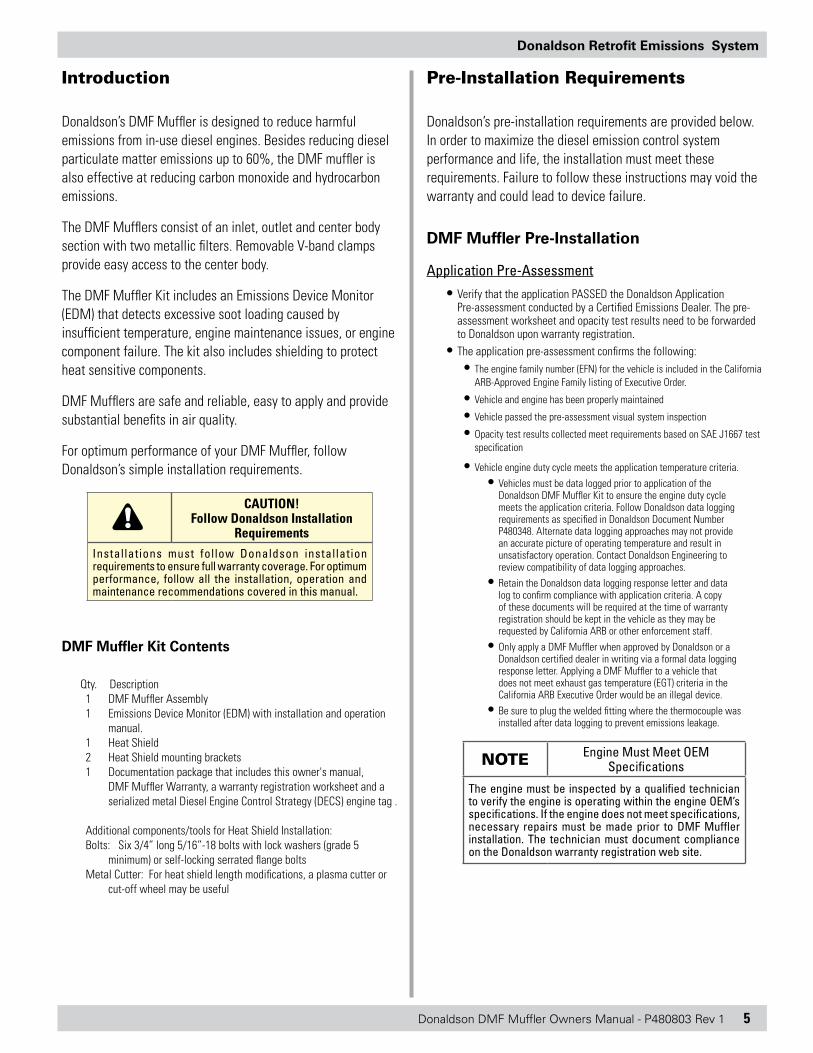
CAUTION! Follow Donaldson Installation
RequirementsInstallations must follow Donaldson installation requirements to ensure full warranty coverage. For optimum performance, follow all the installation, operation and maintenance recommendations covered in this manual.
DMF Muffler Kit Contents
Qty. Description1 DMF Muffler Assembly1 Emissions Device Monitor (EDM) with installation and operation
manual.1 Heat Shield 2 Heat Shield mounting brackets1 Documentation package that includes this owner's manual,
DMF Muffler Warranty, a warranty registration worksheet and a serialized metal Diesel Engine Control Strategy (DECS) engine tag .
Additional components/tools for Heat Shield Installation: Bolts: Six 3/4” long 5/16”-18 bolts with lock washers (grade 5
minimum) or self-locking serrated flange boltsMetal Cutter: For heat shield length modifications, a plasma cutter or
cut-off wheel may be useful
Pre-Installation Requirements
Donaldson’s pre-installation requirements are provided below. In order to maximize the diesel emission control system performance and life, the installation must meet these requirements. Failure to follow these instructions may void the warranty and could lead to device failure.
DMF Muffler Pre-Installation
Application Pre-Assessment• Verify that the application PASSED the Donaldson Application
Pre-assessment conducted by a Certified Emissions Dealer. The pre-assessment worksheet and opacity test results need to be forwarded to Donaldson upon warranty registration.
• The application pre-assessment confirms the following:• The engine family number (EFN) for the vehicle is included in the California
ARB-Approved Engine Family listing of Executive Order.
• Vehicle and engine has been properly maintained
• Vehicle passed the pre-assessment visual system inspection
• Opacity test results collected meet requirements based on SAE J1667 test specification
• Vehicle engine duty cycle meets the application temperature criteria.• Vehicles must be data logged prior to application of the
Donaldson DMF Muffler Kit to ensure the engine duty cycle meets the application criteria. Follow Donaldson data logging requirements as specified in Donaldson Document Number P480348. Alternate data logging approaches may not provide an accurate picture of operating temperature and result in unsatisfactory operation. Contact Donaldson Engineering to review compatibility of data logging approaches.
• Retain the Donaldson data logging response letter and data log to confirm compliance with application criteria. A copy of these documents will be required at the time of warranty registration should be kept in the vehicle as they may be requested by California ARB or other enforcement staff.
• Only apply a DMF Muffler when approved by Donaldson or a Donaldson certified dealer in writing via a formal data logging response letter. Applying a DMF Muffler to a vehicle that does not meet exhaust gas temperature (EGT) criteria in the California ARB Executive Order would be an illegal device.
• Be sure to plug the welded fitting where the thermocouple was installed after data logging to prevent emissions leakage.
NOTE Engine Must Meet OEM Specifications
The engine must be inspected by a qualified technician to verify the engine is operating within the engine OEM’s specifications. If the engine does not meet specifications, necessary repairs must be made prior to DMF Muffler installation. The technician must document compliance on the Donaldson warranty registration web site.
6 Donaldson DMF Muffler Owners Manual - P480803 Rev 1
Donaldson Retrofit Emissions System
ensure the EGT is representative of what the DMF Muffler will see. Minimize the distance from the turbo to the emissions device inlet.
NOTE Mount the DMF Muffler within 6" (305mm) from temperature probe
To optimize performance, the inlet on the new DMF must be installed within 6 inches (152.4 mm) from where the temperature probe was installed during preliminary data logging. Mounting the DMF Muffler beyond this distance may cause frequent cleaning intervals and may result in unsatisfactory / unreliable performance or plugging.
To maximize effectiveness, exhaust tubing should be structurally sound and leak-free. Inspect the exhaust tubing for damage or corrosion, and replace defective components. Also look for flaking due to corrosion and/or soot build-up. Loose contaminants can be blown onto the DMF face and cause increased backpressure and degraded engine performance. Operate engine at high idle to blow out exhaust pipes prior to the installation of the emissions device.
NOTE Rust, Corrosion and Soot on Existing Exhaust Tubing
If you see any evidence of rust or corrosion on existing tubing between the turbocharger and DMF Muffler inlet, replace with new aluminized steel tubing. If reusing existing exhaust tubing, banging and tapping on the tubing may dislodge soot. Be sure to clean out any pipes prior to installing new components. Operate engine at high idle to blow out exhaust pipes prior to the installation of the emissions device. Protect yourself and others from loud noise and flying debris.
CAUTION! Do Not Overtighten Bands or Clamps on Muffler Center
Body
The filters inside the DMF center section could be damaged if you deform the muffler body by overtightening clamps.
Weigh and Record Filter Section
If you plan to use the weight of the filter as a basis to determine the cleanliness of the filter after cleaning, it is recommended that you weigh the new filter section prior to installation or use.
NOTE Weighing the Filter Section
Proper filter weight measurements require removal of the filter section from the muffler assembly and a scale with at least 1.0 gram solution.
Fuel Requirement
DMF Mufflers require the use of ULSD Fuel (15 ppm or less sulfur content) that meets ASTM D975. B20 BioULSD (20% biodiesel/80% ULSD) that meets ASTM D6751 diesel fuel specifications may also be used. Fuel additives are not permitted and may void your warranty.
Engine Lube Oil Requirement
The DMF Mufflers require the use of engine lube oil that meets CJ-4 specifications (low ash).
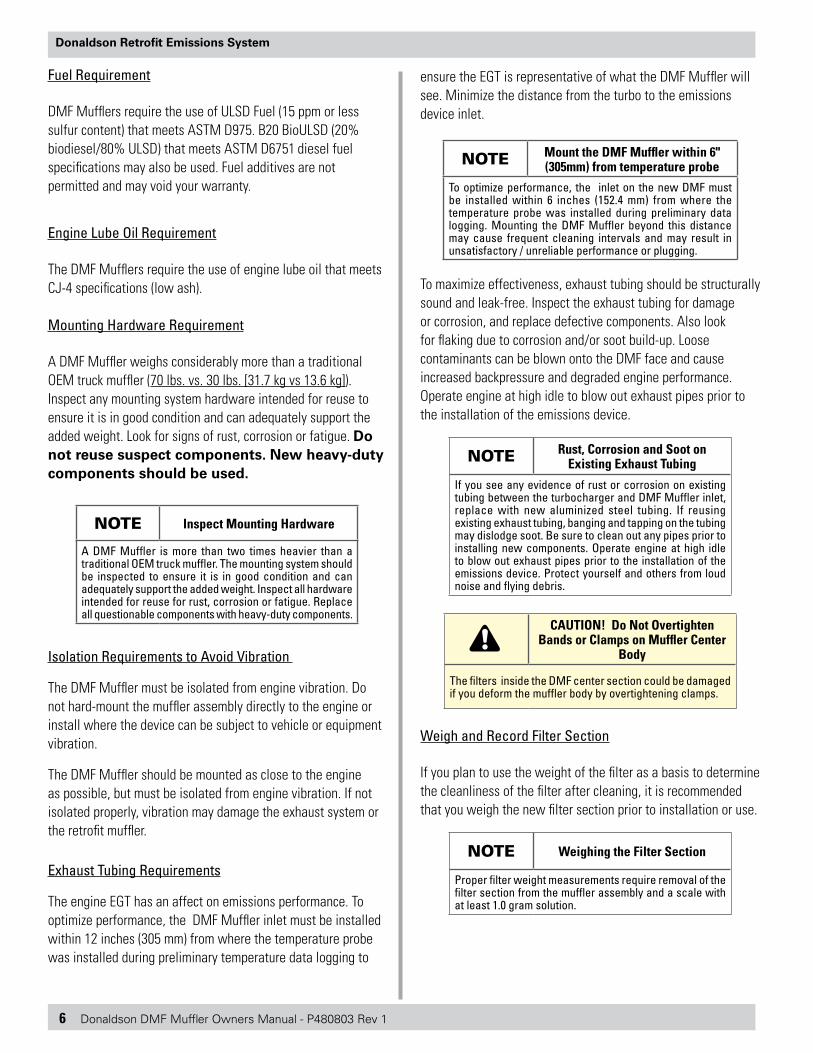
Mounting Hardware Requirement
A DMF Muffler weighs considerably more than a traditional OEM truck muffler (70 lbs. vs. 30 lbs. [31.7 kg vs 13.6 kg]). Inspect any mounting system hardware intended for reuse to ensure it is in good condition and can adequately support the added weight. Look for signs of rust, corrosion or fatigue. Do not reuse suspect components. New heavy-duty components should be used.
NOTE Inspect Mounting Hardware
A DMF Muffler is more than two times heavier than a traditional OEM truck muffler. The mounting system should be inspected to ensure it is in good condition and can adequately support the added weight. Inspect all hardware intended for reuse for rust, corrosion or fatigue. Replace all questionable components with heavy-duty components.
Isolation Requirements to Avoid Vibration
The DMF Muffler must be isolated from engine vibration. Do not hard-mount the muffler assembly directly to the engine or install where the device can be subject to vehicle or equipment vibration.
The DMF Muffler should be mounted as close to the engine as possible, but must be isolated from engine vibration. If not isolated properly, vibration may damage the exhaust system or the retrofit muffler.
Exhaust Tubing Requirements
The engine EGT has an affect on emissions performance. To optimize performance, the DMF Muffler inlet must be installed within 12 inches (305 mm) from where the temperature probe was installed during preliminary temperature data logging to
Donaldson DMF Muffler Owners Manual - P480803 Rev 1 7
Donaldson Retrofit Emissions System
EDM Pre-Installation
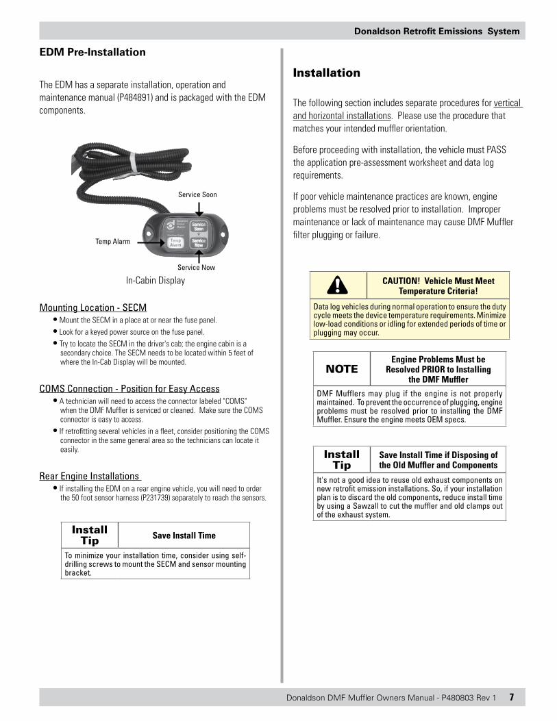
The EDM has a separate installation, operation and maintenance manual (P484891) and is packaged with the EDM components.
Temp Alarm
Service Now
Service Soon
In-Cabin Display
Mounting Location - SECM• Mount the SECM in a place at or near the fuse panel. • Look for a keyed power source on the fuse panel.• Try to locate the SECM in the driver's cab; the engine cabin is a
secondary choice. The SECM needs to be located within 5 feet of where the In-Cab Display will be mounted.
COMS Connection - Position for Easy Access• A technician will need to access the connector labeled "COMS"
when the DMF Muffler is serviced or cleaned. Make sure the COMS connector is easy to access.
• If retrofitting several vehicles in a fleet, consider positioning the COMS connector in the same general area so the technicians can locate it easily.
Rear Engine Installations • If installing the EDM on a rear engine vehicle, you will need to order
the 50 foot sensor harness (P231739) separately to reach the sensors.
Install Tip Save Install Time
To minimize your installation time, consider using self-drilling screws to mount the SECM and sensor mounting bracket.
Installation
The following section includes separate procedures for vertical and horizontal installations. Please use the procedure that matches your intended muffler orientation.
Before proceeding with installation, the vehicle must PASS the application pre-assessment worksheet and data log requirements.
If poor vehicle maintenance practices are known, engine problems must be resolved prior to installation. Improper maintenance or lack of maintenance may cause DMF Muffler filter plugging or failure.
CAUTION! Vehicle Must Meet Temperature Criteria!
Data log vehicles during normal operation to ensure the duty cycle meets the device temperature requirements. Minimize low-load conditions or idling for extended periods of time or plugging may occur.
NOTEEngine Problems Must be
Resolved PRIOR to Installing the DMF Muffler
DMF Mufflers may plug if the engine is not properly maintained. To prevent the occurrence of plugging, engine problems must be resolved prior to installing the DMF Muffler. Ensure the engine meets OEM specs.
Install Tip
Save Install Time if Disposing of the Old Muffler and Components
It's not a good idea to reuse old exhaust components on new retrofit emission installations. So, if your installation plan is to discard the old components, reduce install time by using a Sawzall to cut the muffler and old clamps out of the exhaust system.
8 Donaldson DMF Muffler Owners Manual - P480803 Rev 1
Donaldson Retrofit Emissions System
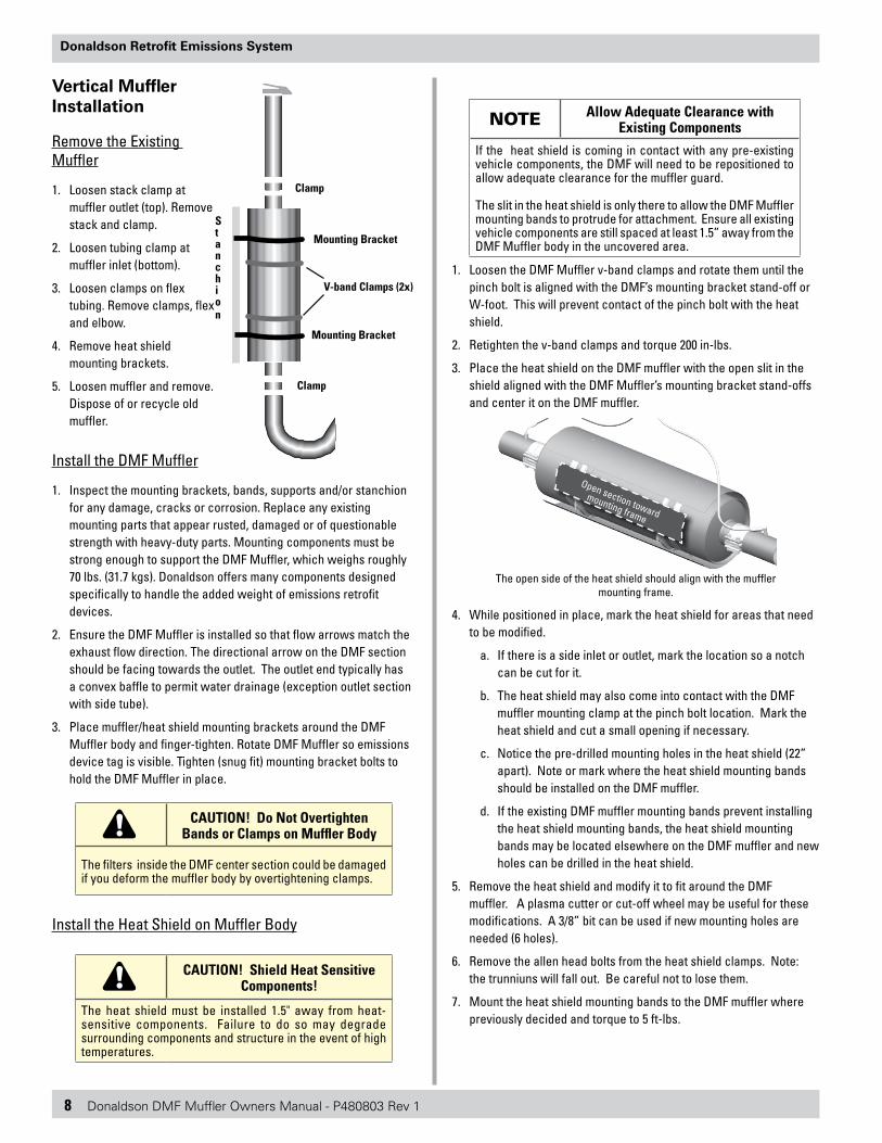
Vertical Muffler Installation
Remove the Existing Muffler
1. Loosen stack clamp at muffler outlet (top). Remove stack and clamp.
2. Loosen tubing clamp at muffler inlet (bottom).
3. Loosen clamps on flex tubing. Remove clamps, flex and elbow.
4. Remove heat shield mounting brackets.
5. Loosen muffler and remove. Dispose of or recycle old muffler.
Install the DMF Muffler
1. Inspect the mounting brackets, bands, supports and/or stanchion for any damage, cracks or corrosion. Replace any existing mounting parts that appear rusted, damaged or of questionable strength with heavy-duty parts. Mounting components must be strong enough to support the DMF Muffler, which weighs roughly 70 lbs. (31.7 kgs). Donaldson offers many components designed specifically to handle the added weight of emissions retrofit devices.
2. Ensure the DMF Muffler is installed so that flow arrows match the exhaust flow direction. The directional arrow on the DMF section should be facing towards the outlet. The outlet end typically has a convex baffle to permit water drainage (exception outlet section with side tube).
3. Place muffler/heat shield mounting brackets around the DMF Muffler body and finger-tighten. Rotate DMF Muffler so emissions device tag is visible. Tighten (snug fit) mounting bracket bolts to hold the DMF Muffler in place.
CAUTION! Do Not Overtighten Bands or Clamps on Muffler Body
The filters inside the DMF center section could be damaged if you deform the muffler body by overtightening clamps.
Install the Heat Shield on Muffler Body
CAUTION! Shield Heat Sensitive Components!
The heat shield must be installed 1.5" away from heat-sensitive components. Failure to do so may degrade surrounding components and structure in the event of high temperatures.
NOTE Allow Adequate Clearance with Existing Components
If the heat shield is coming in contact with any pre-existing vehicle components, the DMF will need to be repositioned to allow adequate clearance for the muffler guard.
The slit in the heat shield is only there to allow the DMF Muffler mounting bands to protrude for attachment. Ensure all existing vehicle components are still spaced at least 1.5” away from the DMF Muffler body in the uncovered area.
1. Loosen the DMF Muffler v-band clamps and rotate them until the pinch bolt is aligned with the DMF’s mounting bracket stand-off or W-foot. This will prevent contact of the pinch bolt with the heat shield.
2. Retighten the v-band clamps and torque 200 in-lbs.
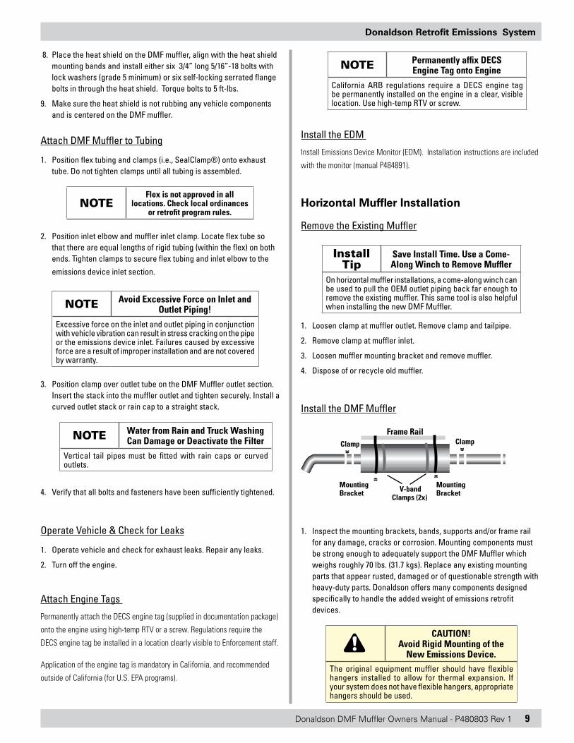
3. Place the heat shield on the DMF muffler with the open slit in the shield aligned with the DMF Muffler’s mounting bracket stand-offs and center it on the DMF muffler.
Open section toward
mounting frame
The open side of the heat shield should align with the muffler mounting frame.
4. While positioned in place, mark the heat shield for areas that need to be modified.
a. If there is a side inlet or outlet, mark the location so a notch can be cut for it.
b. The heat shield may also come into contact with the DMF muffler mounting clamp at the pinch bolt location. Mark the heat shield and cut a small opening if necessary.
c. Notice the pre-drilled mounting holes in the heat shield (22” apart). Note or mark where the heat shield mounting bands should be installed on the DMF muffler.
d. If the existing DMF muffler mounting bands prevent installing the heat shield mounting bands, the heat shield mounting bands may be located elsewhere on the DMF muffler and new holes can be drilled in the heat shield.
5. Remove the heat shield and modify it to fit around the DMF muffler. A plasma cutter or cut-off wheel may be useful for these modifications. A 3/8” bit can be used if new mounting holes are needed (6 holes).
6. Remove the allen head bolts from the heat shield clamps. Note: the trunniuns will fall out. Be careful not to lose them.
7. Mount the heat shield mounting bands to the DMF muffler where previously decided and torque to 5 ft-lbs.
Stanchion
Clamp
Mounting Bracket
Mounting Bracket
Clamp
V-band Clamps (2x)
Donaldson DMF Muffler Owners Manual - P480803 Rev 1 9
Donaldson Retrofit Emissions System
8. Place the heat shield on the DMF muffler, align with the heat shield mounting bands and install either six 3/4” long 5/16”-18 bolts with lock washers (grade 5 minimum) or six self-locking serrated flange bolts in through the heat shield. Torque bolts to 5 ft-lbs.
9. Make sure the heat shield is not rubbing any vehicle components and is centered on the DMF muffler.
Attach DMF Muffler to Tubing
1. Position flex tubing and clamps (i.e., SealClamp®) onto exhaust tube. Do not tighten clamps until all tubing is assembled.
NOTEFlex is not approved in all
locations. Check local ordinances or retrofit program rules.
2. Position inlet elbow and muffler inlet clamp. Locate flex tube so that there are equal lengths of rigid tubing (within the flex) on both ends. Tighten clamps to secure flex tubing and inlet elbow to the
emissions device inlet section.
NOTE Avoid Excessive Force on Inlet and Outlet Piping!
Excessive force on the inlet and outlet piping in conjunction with vehicle vibration can result in stress cracking on the pipe or the emissions device inlet. Failures caused by excessive force are a result of improper installation and are not covered by warranty.
3. Position clamp over outlet tube on the DMF Muffler outlet section. Insert the stack into the muffler outlet and tighten securely. Install a curved outlet stack or rain cap to a straight stack.
NOTE Water from Rain and Truck Washing Can Damage or Deactivate the Filter
Vertical tail pipes must be fitted with rain caps or curved outlets.
4. Verify that all bolts and fasteners have been sufficiently tightened.
Operate Vehicle & Check for Leaks
1. Operate vehicle and check for exhaust leaks. Repair any leaks.
2. Turn off the engine.
Attach Engine Tags
Permanently attach the DECS engine tag (supplied in documentation package)
onto the engine using high-temp RTV or a screw. Regulations require the
DECS engine tag be installed in a location clearly visible to Enforcement staff.
Application of the engine tag is mandatory in California, and recommended
outside of California (for U.S. EPA programs).
NOTE Permanently affix DECS Engine Tag onto Engine
California ARB regulations require a DECS engine tag be permanently installed on the engine in a clear, visible location. Use high-temp RTV or screw.
Install the EDM
Install Emissions Device Monitor (EDM). Installation instructions are included
with the monitor (manual P484891).
Horizontal Muffler Installation
Remove the Existing Muffler
Install Tip
Save Install Time. Use a Come-Along Winch to Remove Muffler
On horizontal muffler installations, a come-along winch can be used to pull the OEM outlet piping back far enough to remove the existing muffler. This same tool is also helpful when installing the new DMF Muffler.
1. Loosen clamp at muffler outlet. Remove clamp and tailpipe.
2. Remove clamp at muffler inlet.
3. Loosen muffler mounting bracket and remove muffler.
4. Dispose of or recycle old muffler.
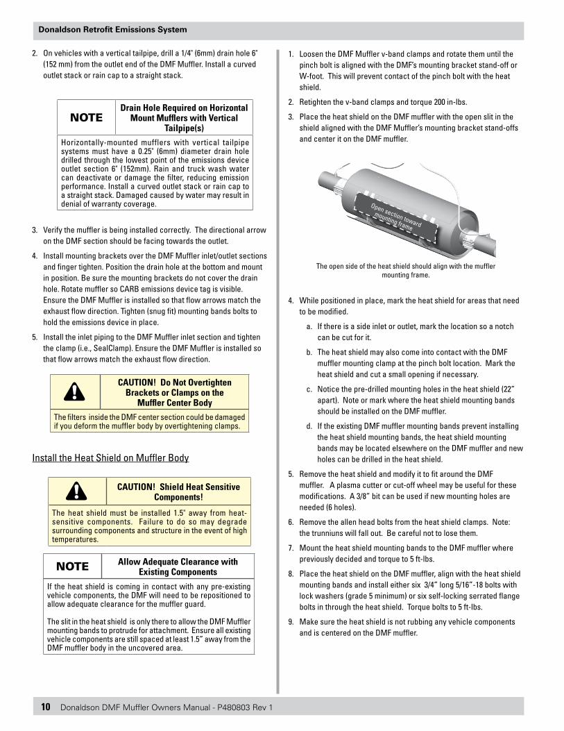
Install the DMF Muffler
«
Clamp
«
Frame Rail
V-band Clamps (2x)
Mounting Bracket
Mounting Bracket
«
Clamp
«
1. Inspect the mounting brackets, bands, supports and/or frame rail for any damage, cracks or corrosion. Mounting components must be strong enough to adequately support the DMF Muffler which weighs roughly 70 lbs. (31.7 kgs). Replace any existing mounting parts that appear rusted, damaged or of questionable strength with heavy-duty parts. Donaldson offers many components designed specifically to handle the added weight of emissions retrofit devices.
CAUTION! Avoid Rigid Mounting of the
New Emissions Device.The original equipment muffler should have flexible hangers installed to allow for thermal expansion. If your system does not have flexible hangers, appropriate hangers should be used.
10 Donaldson DMF Muffler Owners Manual - P480803 Rev 1
Donaldson Retrofit Emissions System
2. On vehicles with a vertical tailpipe, drill a 1/4" (6mm) drain hole 6" (152 mm) from the outlet end of the DMF Muffler. Install a curved outlet stack or rain cap to a straight stack.
NOTEDrain Hole Required on Horizontal
Mount Mufflers with Vertical Tailpipe(s)
Horizontally-mounted mufflers with vertical tailpipe systems must have a 0.25" (6mm) diameter drain hole drilled through the lowest point of the emissions device outlet section 6" (152mm). Rain and truck wash water can deactivate or damage the filter, reducing emission performance. Install a curved outlet stack or rain cap to a straight stack. Damaged caused by water may result in denial of warranty coverage.
3. Verify the muffler is being installed correctly. The directional arrow on the DMF section should be facing towards the outlet.
4. Install mounting brackets over the DMF Muffler inlet/outlet sections and finger tighten. Position the drain hole at the bottom and mount in position. Be sure the mounting brackets do not cover the drain hole. Rotate muffler so CARB emissions device tag is visible. Ensure the DMF Muffler is installed so that flow arrows match the exhaust flow direction. Tighten (snug fit) mounting bands bolts to hold the emissions device in place.
5. Install the inlet piping to the DMF Muffler inlet section and tighten the clamp (i.e., SealClamp). Ensure the DMF Muffler is installed so that flow arrows match the exhaust flow direction.
CAUTION! Do Not Overtighten Brackets or Clamps on the
Muffler Center BodyThe filters inside the DMF center section could be damaged if you deform the muffler body by overtightening clamps.
Install the Heat Shield on Muffler Body
CAUTION! Shield Heat Sensitive Components!
The heat shield must be installed 1.5" away from heat-sensitive components. Failure to do so may degrade surrounding components and structure in the event of high temperatures.
NOTE Allow Adequate Clearance with Existing Components
If the heat shield is coming in contact with any pre-existing vehicle components, the DMF will need to be repositioned to allow adequate clearance for the muffler guard.
The slit in the heat shield is only there to allow the DMF Muffler mounting bands to protrude for attachment. Ensure all existing vehicle components are still spaced at least 1.5” away from the DMF muffler body in the uncovered area.
1. Loosen the DMF Muffler v-band clamps and rotate them until the pinch bolt is aligned with the DMF’s mounting bracket stand-off or W-foot. This will prevent contact of the pinch bolt with the heat shield.
2. Retighten the v-band clamps and torque 200 in-lbs.
3. Place the heat shield on the DMF muffler with the open slit in the shield aligned with the DMF Muffler’s mounting bracket stand-offs and center it on the DMF muffler.
Open section toward
mounting frame
The open side of the heat shield should align with the muffler mounting frame.
4. While positioned in place, mark the heat shield for areas that need to be modified.
a. If there is a side inlet or outlet, mark the location so a notch can be cut for it.
b. The heat shield may also come into contact with the DMF muffler mounting clamp at the pinch bolt location. Mark the heat shield and cut a small opening if necessary.
c. Notice the pre-drilled mounting holes in the heat shield (22” apart). Note or mark where the heat shield mounting bands should be installed on the DMF muffler.
d. If the existing DMF muffler mounting bands prevent installing the heat shield mounting bands, the heat shield mounting bands may be located elsewhere on the DMF muffler and new holes can be drilled in the heat shield.
5. Remove the heat shield and modify it to fit around the DMF muffler. A plasma cutter or cut-off wheel may be useful for these modifications. A 3/8” bit can be used if new mounting holes are needed (6 holes).
6. Remove the allen head bolts from the heat shield clamps. Note: the trunniuns will fall out. Be careful not to lose them.
7. Mount the heat shield mounting bands to the DMF muffler where previously decided and torque to 5 ft-lbs.
8. Place the heat shield on the DMF muffler, align with the heat shield mounting bands and install either six 3/4” long 5/16”-18 bolts with lock washers (grade 5 minimum) or six self-locking serrated flange bolts in through the heat shield. Torque bolts to 5 ft-lbs.
9. Make sure the heat shield is not rubbing any vehicle components and is centered on the DMF muffler.

Donaldson DMF Muffler Owners Manual - P480803 Rev 1 11
Donaldson Retrofit Emissions System
Attach DMF Muffler to Tubing
1. Install tailpipe and secure clamp (i.e., SealClamp) on emissions device outlet section.
2. Verify that all bolts and fasteners have been sufficiently tightened.
Operate Vehicle & Check for Leaks
1. Operate vehicle and check for exhaust leaks. Repair any leaks.
2. Turn off the engine.
Attach Engine Tags
Permanently attach the DECS engine tag (supplied in documentation package) onto the engine using high-temp RTV or a screw. CARB regulations require the DECS engine tag be installed in a location clearly visible to Enforcement staff. Application of the engine tag is mandatory in California, and recommended outside of California (for U.S. EPA programs).
NOTE Permanently affix DECS Engine Tag onto Engine
California ARB regulations require a DECS engine tag be permanently installed on the engine in a clear, visible location. Use high-temp RTV or screw.
Install the EDM
Install Emissions Device Monitor (EDM). Installation instructions will be included with the monitor (manual P484891).
Installation Checklist
DMF Muffler
❏ DMF Muffler mounted in proper exhaust flow direction
❏ All DMF Muffler mounting hardware and clamps are tightened.
❏ Heat shield installed to protect sensitive components (1.5" clearance)
❏ New hardware and clamps installed per this manual or CHP drawing (school bus only)
❏ No visible exhaust leaks in the system
Emissions Device Monitor (EDM)
❏ No dips, kinks or low spots in stainless steel braided hose (must have an uphill path to pressure transducer to avoid water damage)
❏ Pressure transducer threaded barb points downward to prevent water damage
❏ Temperature probe wire secured at least 6” (152 mm) away from hot exhaust pipes
❏ In-Cab Display mounted in sight of the vehicle operator
❏ COMS connection on wiring harness mounted in a location that can be easily accessed by the mechanic
❏ All wiring harnesses secure at least 6” (152 mm) away from high heat and moving parts
❏ All connectors mated securely
❏ Memory module plugged in
❏ 12V DC, 10A fuse-protected, keyed power attached and grounded
❏ Any wires mounted through holes must have hole edges protected by a grommet
❏ Wires should be protected in looms
❏ Wiring between two members where relative motion can occur should be secured to each member and have enough slack to allow motion without damage to the wire.
❏ At key-up, all three LED lights on the In-Cab display blink for three seconds
12 Donaldson DMF Muffler Owners Manual - P480803 Rev 1
Donaldson Retrofit Emissions System
❏ Vehicle operators trained on new In-Cab Display and alerts
❏ Complete Vehicle Setup: Connect laptop with COMS port and enter information into SECM “Vehicle Setup” (VIN, Diesel Emission Control Strategy [DECS] Serial No., install date, etc.)
Program Compliance
❏ ARB engine tag permanently affixed to the engine with RTV silicone in a visible location
❏ End user has warranty document, pre-assessment worksheet, temperature data log, Donaldson response letter and this manual for their records.
❏ Warranty activated and documentation submitted to Donaldson on http://pwww.donaldson.com
Activate the Warranty
For regulatory reporting and warranty registration purposes, Donaldson Company requires the installer/dealer to complete and submit the warranty for the vehicle or equipment owner on our web site at http://pwww.donaldson.com.
Supporting documents are also required at time of Registering: The warranty registration web site requires that you upload the (1) Application Pre-assessment Worksheet (F114050), and the (2) Opacity Test and (3) Data Logging results for the vehicle/equipment being registered.
A Warranty Registration Worksheet is included in the documentation packet Register the new installation within 30 days using our on-line warranty registration site at: http://pwww.donaldson.com
Emissions Retrofit Documentation
Retain all emissions retrofit documentation on each vehicle; including
• Application pre-assessment worksheet from dealer including opacity test results and temperature data logging
• Donaldson (or dealer) response letter that approved the retrofit application with signatures
• Date of installation• Mileage / hours at install• Installation and owner information• Part number • Serial number• Service and cleaning records
Operation
Donaldson DMF Mufflers are designed and verified for use on on-road medium- and heavy-duty truck and bus applications. To ensure proper functioning of these products, the Donaldson preventive maintenance and service procedures must be incorporated into your regular vehicle maintenance routines.
The EDM monitors the backpressure and temperature of the system, and alerts the operator of engine malfunctions that affect device operation or device service requirements via the In-Cab Display. The SERVICE SOON light alerts the operator that a cleaning will be necessary in the coming week. The SERVICE NOW light indicates that a cleaning is necessary within 8 hours of operation or before the next work shift, whichever comes first.
NOTESee EDM Manual for details on the
In-Cab Display Alerts & Actions The information below is an
excerpt from the manual.
To ensure proper functioning of these products, Donaldson preventative maintenance and service procedures must be incorporated into your regular vehicle maintenance routines.
Maintenance and Service
DPF Section Service Records
Donaldson requires that the accurate and thorough records be maintained of any service and cleaning performed on your DMF Muffler.
CAUTION! Maintain Proper Maintenance Records!
Donaldson DMF Mufflers are regulated emission control devices. Failure to show accurate and thorough service records upon request of regulator agency compliance inspections may result in warnings, fines or vehicle shut-down.
To ensure compliance, the end-user is required to maintain the following information at the completion of any service occurrence:
• Date and mileage and/or hours if or when the filter section is cleaned or service in any manner
• DECS serial number
• DMF Muffler Kit number
Donaldson DMF Muffler Owners Manual - P480803 Rev 1 13
Donaldson Retrofit Emissions System
Routine Inspections During Vehicle Service
The following preventive maintenance recommendations should be conducted during normally scheduled vehicle maintenance.1. Inspect the emissions device, exhaust piping and mounting
brackets.
2. Look for leaks, structural failures (cracks) and loose or missing fasteners.
3. Repair or replace defective parts, as appropriate.
CAUTION! Do Not Use Fuels Blended with Lube Oil or Additives
Engine oil must not be blended with the engine's fuel. Fuel blended with oil may cause deposits in the filter that increase backpressure, reduce engine performance and may result in denial of warranty coverage. The use of an unapproved additive may result in denial of warranty coverage.
CAUTION! Do Not Modify Engines
Electronically controlled engines are certified with a specific fuel and electronic program based on engine configuration and model year. Use only the fuel and electronic program specified for your engine. Using the incorrect fuel and/or electronic program may cause excessive soot generation and DPF plugging and may result in denial of warranty coverage.
CAUTION! Monitor Lube Oil Consumption
Certain components found in engine lube oil can poison catalysts. To protect against filter failure and/or plugging, ensure that the engine is not consuming oil at a rate higher than specified by the engine manufacturer. Use low ash oils (CJ-4). Do not use fuel blended with lube oil. Fuel additives may not be used without written approval from Donaldson. The use of an unapproved additive may result in denial of warranty coverage.
Filter Cleaning The filtering device is located in the center body of the DMF Muffler. Filter plugging is uncommon, but can occur via excess soot loading caused by insufficient temperature, engine maintenance issues or engine component failures. If cleaning is required, contact Donaldson for filter cleaning instructions.
NOTE No Routine Ash Cleaning
The DMF Muffler does not typically require or need routine service during its life. Service will only be needed if it is misapplied or poor engine conditions increase soot output to an abnormally high level. If cleaning is required, contact Donaldson for instructions.
Filter Disposal Information
The filter section in the DMF Muffler contains precious metal catalyst to reduce carbon monoxide, hydrocarbons and diesel particulate matter emissions. Typical metals may include platinum, palladium and rhodium. These materials can be recycled from damaged or deactivated DMF Mufflers. Please dispose of DMF Mufflers in accordance with local regulations and laws; recycle when possible.
14 Donaldson DMF Muffler Owners Manual - P480803 Rev 1
Donaldson Retrofit Emissions System
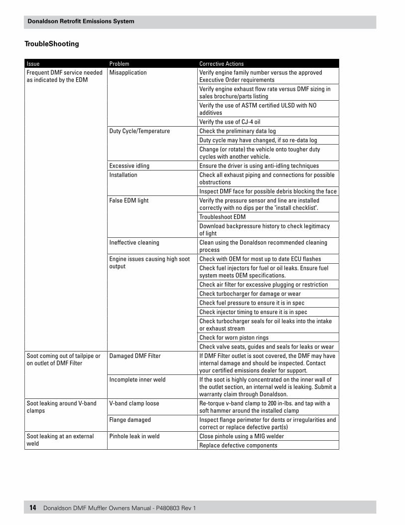
TroubleShooting
Issue Problem Corrective ActionsFrequent DMF service needed as indicated by the EDM
Misapplication Verify engine family number versus the approved Executive Order requirementsVerify engine exhaust flow rate versus DMF sizing in sales brochure/parts listingVerify the use of ASTM certified ULSD with NO additivesVerify the use of CJ-4 oil
Duty Cycle/Temperature Check the preliminary data logDuty cycle may have changed, if so re-data logChange (or rotate) the vehicle onto tougher duty cycles with another vehicle.
Excessive idling Ensure the driver is using anti-idling techniquesInstallation Check all exhaust piping and connections for possible
obstructionsInspect DMF face for possible debris blocking the face
False EDM light Verify the pressure sensor and line are installed correctly with no dips per the "install checklist".Troubleshoot EDMDownload backpressure history to check legitimacy of light
Ineffective cleaning Clean using the Donaldson recommended cleaning process
Engine issues causing high soot output
Check with OEM for most up to date ECU flashesCheck fuel injectors for fuel or oil leaks. Ensure fuel system meets OEM specifications.Check air filter for excessive plugging or restrictionCheck turbocharger for damage or wearCheck fuel pressure to ensure it is in specCheck injector timing to ensure it is in specCheck turbocharger seals for oil leaks into the intake or exhaust streamCheck for worn piston ringsCheck valve seats, guides and seals for leaks or wear
Soot coming out of tailpipe or on outlet of DMF Filter
Damaged DMF Filter If DMF Filter outlet is soot covered, the DMF may have internal damage and should be inspected. Contact your certified emissions dealer for support.
Incomplete inner weld If the soot is highly concentrated on the inner wall of the outlet section, an internal weld is leaking. Submit a warranty claim through Donaldson.
Soot leaking around V-band clamps
V-band clamp loose Re-torque v-band clamp to 200 in-lbs. and tap with a soft hammer around the installed clamp
Flange damaged Inspect flange perimeter for dents or irregularities and correct or replace defective part(s)
Soot leaking at an external weld
Pinhole leak in weld Close pinhole using a MIG welderReplace defective components
Donaldson DMF Muffler Owners Manual - P480803 Rev 1 15
Donaldson Retrofit Emissions System
Actions and Improper Maintenance That May Result in Denial of Your Warranty Coverage
Prior to installing any DMF Muffler unit, a vehicle profile sheet must be completed by the equipment owner and approved by Donaldson. Failure to obtain this approval may void this warranty.
The following conditions are considered to be abuse, neglect or improper maintenance that may result in denial of warranty coverage:
• Failure to follow Engine Original Equipment Manufacturer (OEM) maintenance and operating procedures. Proper maintenance and operating procedures are understood to be those procedures recommended by the OEM to ensure engine longevity and proper operation.
• Excessive particulate emissions due to poor engine operation and maintenance.
• Misapplication to an engine model or to a duty cycle other than that which it is designed and approved.
• Improper installation (strict adherence to the Donaldson owners manual is required).
• Alterations or attempted repairs.• Progressive engine failure that allows lube oil, fuel
or coolant to be present in the engine exhaust, in excess of OEM specifications.Use of fuel: (a) other than that for which the engine is calibrated
or other than recommended by Donaldson. (b) containing other than ultra low sulfur diesel or not
approved in writing by Donaldson, or fuel other than that which is specifically required to achieve the emissions required.
(c) blended fuel with lube oil, kerosene, fuel additives or other materials not approved in writing by Donaldson.
• Excessive lube oil consumption.• Physical damage caused by misuse, abuse or road
hazards including (but not limited to) dents, cuts or fractures.
• Damage caused by improper cleaning procedures (failure to adhere to Donaldson recommended cleaning guidelines).
• Failures or damage caused by mounting system failures.
• Damage to the filter section or plugging caused by water entry.
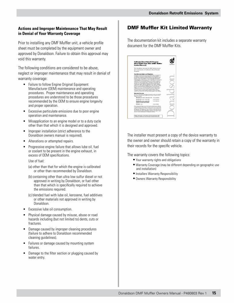
DMF Muffler Kit Limited Warranty
The documentation kit includes a separate warranty document for the DMF Muffler Kits.
The installer must present a copy of the device warranty to the owner and owner should retain a copy of the warranty in their records for the specific vehicle.
The warranty covers the following topics:• Your warranty rights and obligations• Warranty Coverage (may be different depending on geographic use
and installation)• Installers Warranty Responsibility• Owners Warranty Responsibility

Technical Support [email protected]
Donaldson Company, Inc.Minneapolis, MN 55440-1299www.donaldsonexhaust.com
© 2010 Donaldson Company, Inc. IOM P480803, Revision 1All rights reserved. Printed in USA March 2010