Embed Size (px)
Citation preview

N° : 262-3055-UK Rev. : 06 Date : 05/04
INSTALLATION AND OPERATION
MANUAL
For Torit Environmental Control Booth (Including ECB Filtration Module, ECB Power Module,
ECB-2, ECB-3, ECB-4)
G Please read this manual prior to installation and/or setting-up.
- 2 -
TABLE OF CONTENTS 1. SAFETY RECOMMENDATIONS ....................................................................................3 2. INTRODUCTION ............................................................................................................4
2.1 Product information ...................................................................................................4 2.2 Function ....................................................................................................................5
3. PRIOR TO INSTALLATION ............................................................................................5 3.1 Location ....................................................................................................................5 3.2 Required tools and equipment...................................................................................6 3.3 Delivery and inspection .............................................................................................6
4. INSTALLATION ..............................................................................................................6 4.1 Unloading and transport to location...........................................................................6 4.2 Installation and assembly ..........................................................................................7
4.2.1 Multiple power module installation .....................................................................................................................7 4.2.2 Booth pack assembly (see figure ‘Booth Pack Assembly’).................................................................................7 4.2.3 Afterfilters (see figure ‘Afterfilter’).......................................................................................................................9 4.2.4 In- and Outlets.................................................................................................................................................10 4.2.5 Control Box......................................................................................................................................................10 4.2.6 Compressed Air Connection............................................................................................................................10 4.2.7 Electrical connection........................................................................................................................................11 4.2.8 Controlbox assembly .......................................................................................................................................11 4.2.9 Light fixtures ....................................................................................................................................................15
5. START-UP CHECKLIST ...............................................................................................15 6. OPERATION SCHEDULE.............................................................................................15 7. SERVICE ......................................................................................................................16
7.1 Dust removal ...........................................................................................................16 7.2 Change of filter elements ........................................................................................16 7.3 Diaphragm valve : Valve disassembly and reassembly ...........................................17
8. TROUBLE SHOOTING GUIDE.....................................................................................19 9. SPARE PARTS.............................................................................................................20
9.1 Inlet Packs ..............................................................................................................22 9.2 Roof Pack ...............................................................................................................23 9.3 Joining Pack............................................................................................................23 9.4 Lighting Pack ..........................................................................................................24 9.5 Magnehelic Pack.....................................................................................................24
10. CONTACT ADDRESSES ...........................................................................................25 11. CE DECLARATION....................................................................................................26
LIST OF FIGURES FIGURE 1 : TYPICAL INSTALLATION VIEW .........................................................................................................................................4 FIGURE 2 : OPERATIONAL SCHEMATIC.............................................................................................................................................5 FIGURE 3: SINGLE POWER MODULE INSTALLATION/ASSEMBLY ..........................................................................................................6 FIGURE 4 : MULTIPLE POWER MODULE INSTALLATION/ASSEMBLY......................................................................................................7 FIGURE 5 : BOOTH PACK ASSEMBLY ...............................................................................................................................................8 FIGURE 6 : LIGHT INSTALLATION .....................................................................................................................................................9 FIGURE 7 : AFTERFILTER ................................................................................................................................................................9 FIGURE 8 : INSTALLATION OF HEPA FILTER - VERTICAL FLOW ...........................................................................................................10 FIGURE 9 : TYPICAL WIRING DIAGRAM...........................................................................................................................................12 FIGURE 10 : TOP VIEW (UTILITY CONNECTIONS) .............................................................................................................................13 FIGURE 11 : DELTA P CONNECTION...............................................................................................................................................13 FIGURE 12 : GAGE/TUBING INSTALLATION .....................................................................................................................................14 FIGURE 13 : FAN ELECTRICAL CONNECTION - ECB-3.....................................................................................................................14 FIGURE 14 : EXCHANGING FILTER ELEMENT ..................................................................................................................................17 FIGURE 15 : DIAPHRAGM VALVE ...................................................................................................................................................18
- 3 -
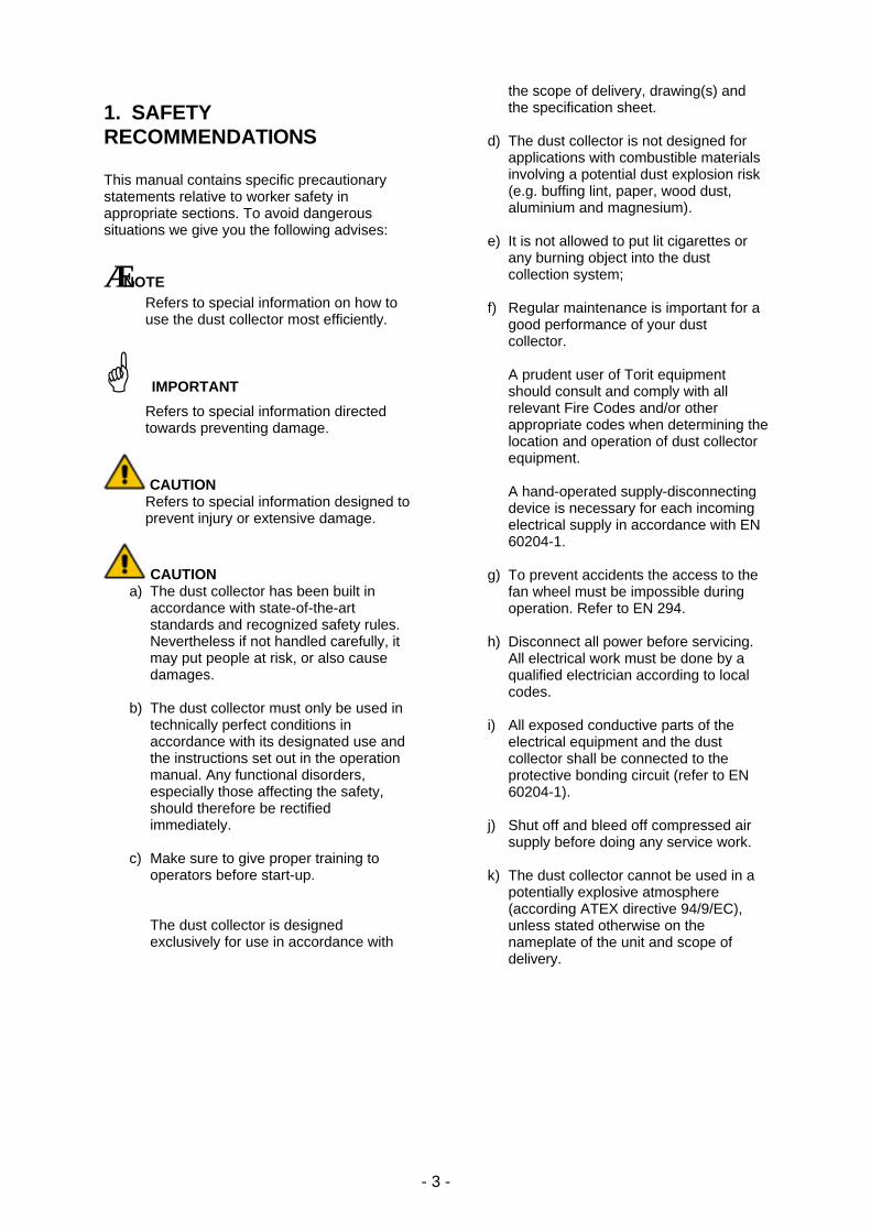
1. SAFETY RECOMMENDATIONS This manual contains specific precautionary statements relative to worker safety in appropriate sections. To avoid dangerous situations we give you the following advises:
⟨ NOTE Refers to special information on how to use the dust collector most efficiently.
G IMPORTANT
Refers to special information directed towards preventing damage.
CAUTION Refers to special information designed to prevent injury or extensive damage.
CAUTION a) The dust collector has been built in
accordance with state-of-the-art standards and recognized safety rules. Nevertheless if not handled carefully, it may put people at risk, or also cause damages.
b) The dust collector must only be used in
technically perfect conditions in accordance with its designated use and the instructions set out in the operation manual. Any functional disorders, especially those affecting the safety, should therefore be rectified immediately.
c) Make sure to give proper training to
operators before start-up.
The dust collector is designed exclusively for use in accordance with
the scope of delivery, drawing(s) and the specification sheet.
d) The dust collector is not designed for
applications with combustible materials involving a potential dust explosion risk (e.g. buffing lint, paper, wood dust, aluminium and magnesium).
e) It is not allowed to put lit cigarettes or
any burning object into the dust collection system;
f) Regular maintenance is important for a
good performance of your dust collector. A prudent user of Torit equipment should consult and comply with all relevant Fire Codes and/or other appropriate codes when determining the location and operation of dust collector equipment. A hand-operated supply-disconnecting device is necessary for each incoming electrical supply in accordance with EN 60204-1.
g) To prevent accidents the access to the
fan wheel must be impossible during operation. Refer to EN 294.
h) Disconnect all power before servicing.
All electrical work must be done by a qualified electrician according to local codes.
i) All exposed conductive parts of the
electrical equipment and the dust collector shall be connected to the protective bonding circuit (refer to EN 60204-1).
j) Shut off and bleed off compressed air
supply before doing any service work.
k) The dust collector cannot be used in a potentially explosive atmosphere (according ATEX directive 94/9/EC), unless stated otherwise on the nameplate of the unit and scope of delivery.
- 4 -
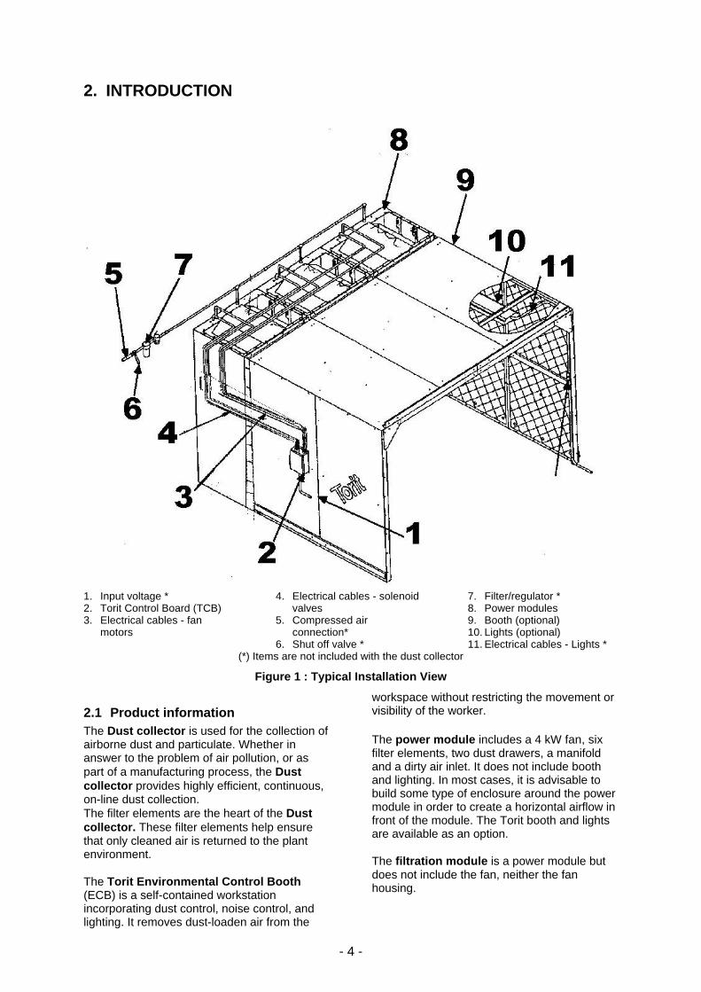
2. INTRODUCTION
1. Input voltage * 2. Torit Control Board (TCB) 3. Electrical cables - fan
motors
4. Electrical cables - solenoid valves
5. Compressed air connection*
6. Shut off valve *
7. Filter/regulator * 8. Power modules 9. Booth (optional) 10. Lights (optional) 11. Electrical cables - Lights *
(*) Items are not included with the dust collector
Figure 1 : Typical Installation View
2.1 Product information The Dust collector is used for the collection of airborne dust and particulate. Whether in answer to the problem of air pollution, or as part of a manufacturing process, the Dust collector provides highly efficient, continuous, on-line dust collection. The filter elements are the heart of the Dust collector. These filter elements help ensure that only cleaned air is returned to the plant environment. The Torit Environmental Control Booth (ECB) is a self-contained workstation incorporating dust control, noise control, and lighting. It removes dust-loaden air from the
workspace without restricting the movement or visibility of the worker. The power module includes a 4 kW fan, six filter elements, two dust drawers, a manifold and a dirty air inlet. It does not include booth and lighting. In most cases, it is advisable to build some type of enclosure around the power module in order to create a horizontal airflow in front of the module. The Torit booth and lights are available as an option. The filtration module is a power module but does not include the fan, neither the fan housing.

- 5 -
ECB2, ECB3 and ECB4 configurations contain the number of power modules designated, and a booth. An overhead light is provided with each module. Acoustical panels attached to the booth are available as an option. Technical and field support are available from your local Torit Representative or Distributors to answer your questions.
2.2 Function During operation, contaminated air enters the Dust collector through the dirty air inlet and passes through the filter elements.
Dust is collected on the outside surface of the filter elements. The filtered air flows through the center of the filter elements into the clean air chamber, where it exits through the clean air outlet and can be recirculated into the environment. To ensure the optimal performance of your dust collector it is necessary that the filter elements are cleaned automatically and sequentially. During the filter cleaning sequence, the timer energises a solenoid valve, causing the corresponding diaphragm valve to send a pulse of compressed air through the filter elements (from the inside outward), removing the collected dust from the outside surfaces of the filter elements. The dust falls into the dust drawers.
Normal Operation Filter Cleaning Operation 1. Clean air outlet 2. Fan box 3. 4 kW Fan
4. Clean air chamber 5. Dirty air inlet 6. Filter element
7. Diaphragm valve 8. Air pulse 9. Dust drawers
Figure 2 : Operational Schematic
3. PRIOR TO INSTALLATION
3.1 Location The dust collector should be located with consideration for: • emptying the dust disposal (item 9, fig. 2) • easy access to electrical and compressed
air connections • convenience of maintenance.
⟨ NOTE Consult the technical specification sheet and drawings for the dust collector weight and dimensions.
No special foundation other than a solid level floor surface is required.
- 6 -
3.2 Required tools and equipment • Crane/Forklift • Slings/ Clevis Pins and adequate lifting
equipment • Standard tools (e.g. screwdrivers,
wrenches, etc.) • Drill • Pipe sealant
3.3 Delivery and inspection
⟨ NOTE The Dust collector is normally shipped by truck as a completely mounted dust collector and should be checked for any damage that may have occurred during shipping. Compare the parts received against the packing list. If there is damage or parts missing, notify the delivery company and your local Torit representative.
Parts shipped loose with the delivery (depending on your order): • Joining pack (for multiple power modules) • Control box • Hepa pack • Inlet pack
• Booth pack • Acoustical panel pack • Lighting pack • Spare parts • Hardware/Sealant
4. INSTALLATION
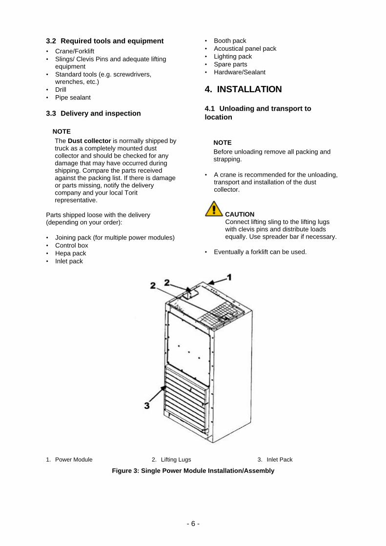
4.1 Unloading and transport to location
⟨ NOTE Before unloading remove all packing and strapping.
• A crane is recommended for the unloading,
transport and installation of the dust collector.
CAUTION Connect lifting sling to the lifting lugs with clevis pins and distribute loads equally. Use spreader bar if necessary.
• Eventually a forklift can be used.
1. Power Module 2. Lifting Lugs 3. Inlet Pack
Figure 3: Single Power Module Installation/Assembly
- 7 -
4.2 Installation and assembly
⟨ NOTE If one of the following equipment is ordered and not mounted please follow the according instructions.
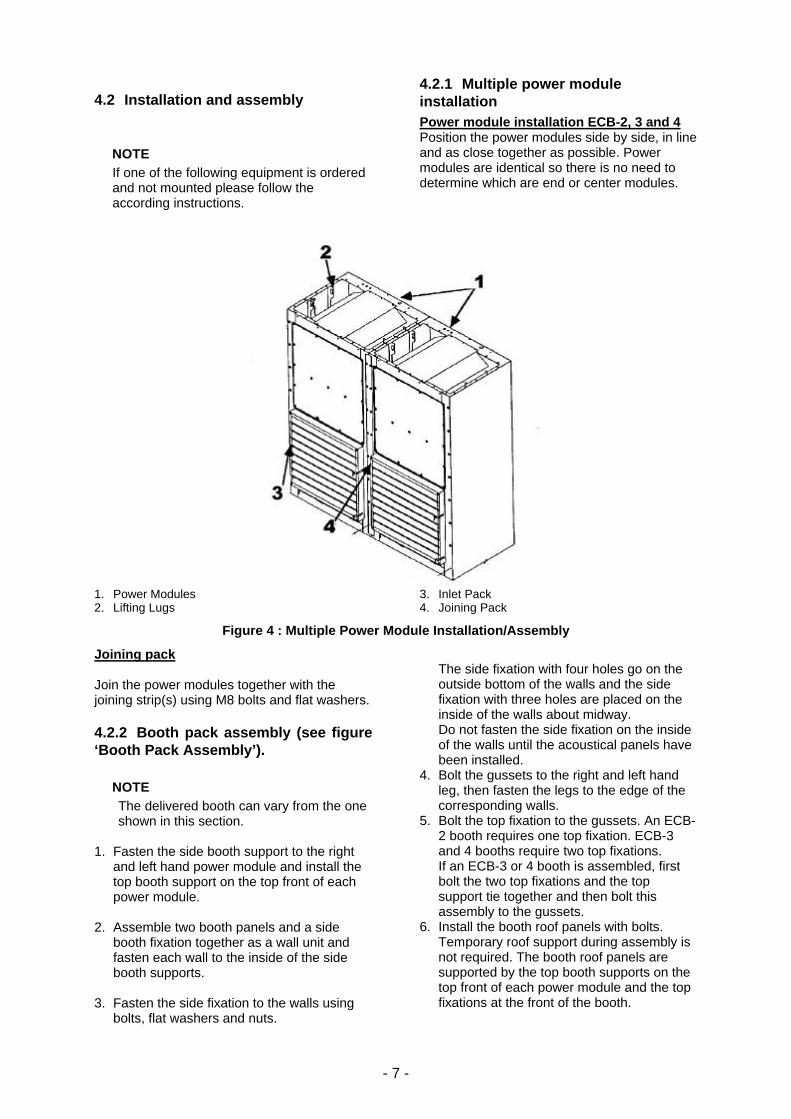
4.2.1 Multiple power module installation Power module installation ECB-2, 3 and 4 Position the power modules side by side, in line and as close together as possible. Power modules are identical so there is no need to determine which are end or center modules.
1. Power Modules 2. Lifting Lugs
3. Inlet Pack 4. Joining Pack
Figure 4 : Multiple Power Module Installation/Assembly
Joining pack Join the power modules together with the joining strip(s) using M8 bolts and flat washers.
4.2.2 Booth pack assembly (see figure ‘Booth Pack Assembly’).
⟨ NOTE The delivered booth can vary from the one shown in this section.
1. Fasten the side booth support to the right
and left hand power module and install the top booth support on the top front of each power module.
2. Assemble two booth panels and a side
booth fixation together as a wall unit and fasten each wall to the inside of the side booth supports.
3. Fasten the side fixation to the walls using
bolts, flat washers and nuts.
The side fixation with four holes go on the outside bottom of the walls and the side fixation with three holes are placed on the inside of the walls about midway. Do not fasten the side fixation on the inside of the walls until the acoustical panels have been installed.
4. Bolt the gussets to the right and left hand leg, then fasten the legs to the edge of the corresponding walls.
5. Bolt the top fixation to the gussets. An ECB-2 booth requires one top fixation. ECB-3 and 4 booths require two top fixations. If an ECB-3 or 4 booth is assembled, first bolt the two top fixations and the top support tie together and then bolt this assembly to the gussets.
6. Install the booth roof panels with bolts. Temporary roof support during assembly is not required. The booth roof panels are supported by the top booth supports on the top front of each power module and the top fixations at the front of the booth.
- 8 -
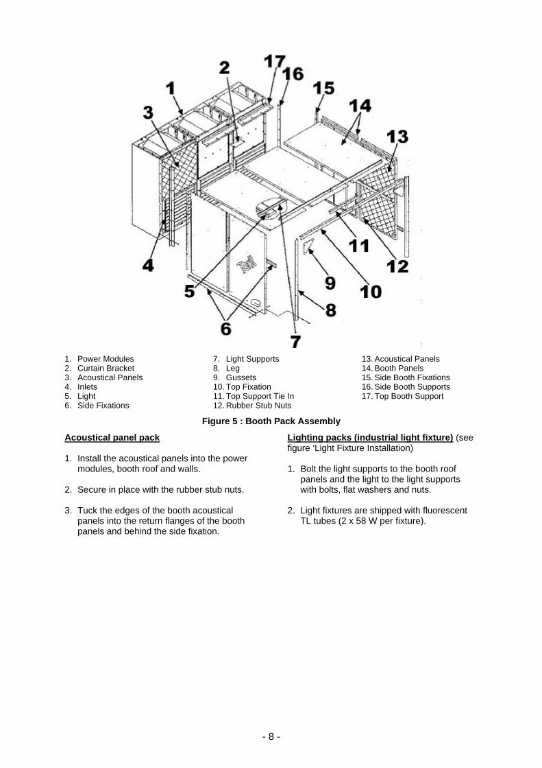
1. Power Modules 2. Curtain Bracket 3. Acoustical Panels 4. Inlets 5. Light 6. Side Fixations
7. Light Supports 8. Leg 9. Gussets 10. Top Fixation 11. Top Support Tie In 12. Rubber Stub Nuts
13. Acoustical Panels 14. Booth Panels 15. Side Booth Fixations 16. Side Booth Supports 17. Top Booth Support
Figure 5 : Booth Pack Assembly
Acoustical panel pack 1. Install the acoustical panels into the power
modules, booth roof and walls. 2. Secure in place with the rubber stub nuts. 3. Tuck the edges of the booth acoustical
panels into the return flanges of the booth panels and behind the side fixation.
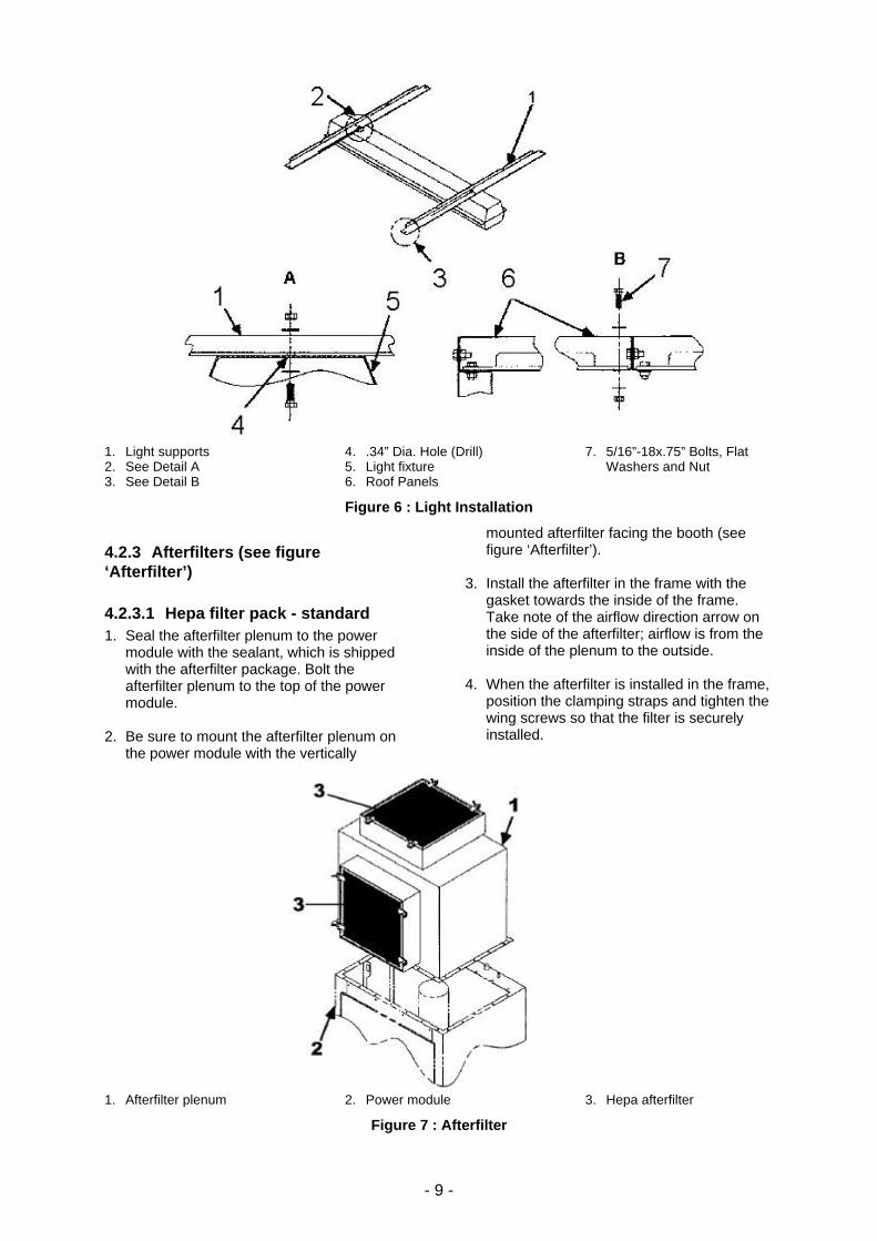
Lighting packs (industrial light fixture) (see figure ‘Light Fixture Installation) 1. Bolt the light supports to the booth roof
panels and the light to the light supports with bolts, flat washers and nuts.
2. Light fixtures are shipped with fluorescent
TL tubes (2 x 58 W per fixture).
- 9 -
1. Light supports 2. See Detail A 3. See Detail B
4. .34” Dia. Hole (Drill) 5. Light fixture 6. Roof Panels
7. 5/16”-18x.75” Bolts, Flat Washers and Nut
Figure 6 : Light Installation
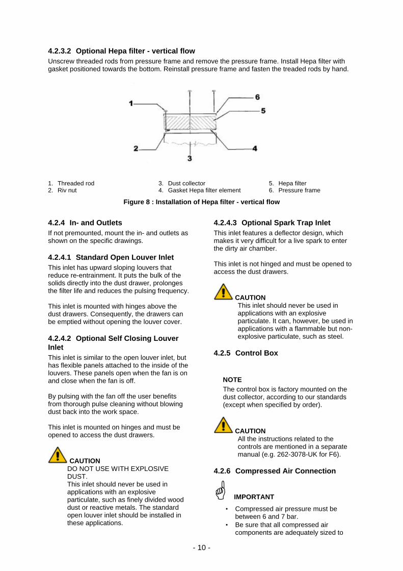
4.2.3 Afterfilters (see figure ‘Afterfilter’)
4.2.3.1 Hepa filter pack - standard 1. Seal the afterfilter plenum to the power
module with the sealant, which is shipped with the afterfilter package. Bolt the afterfilter plenum to the top of the power module.
2. Be sure to mount the afterfilter plenum on
the power module with the vertically
mounted afterfilter facing the booth (see figure ‘Afterfilter’).
3. Install the afterfilter in the frame with the
gasket towards the inside of the frame. Take note of the airflow direction arrow on the side of the afterfilter; airflow is from the inside of the plenum to the outside.
4. When the afterfilter is installed in the frame,
position the clamping straps and tighten the wing screws so that the filter is securely installed.
1. Afterfilter plenum 2. Power module 3. Hepa afterfilter
Figure 7 : Afterfilter
- 10 -
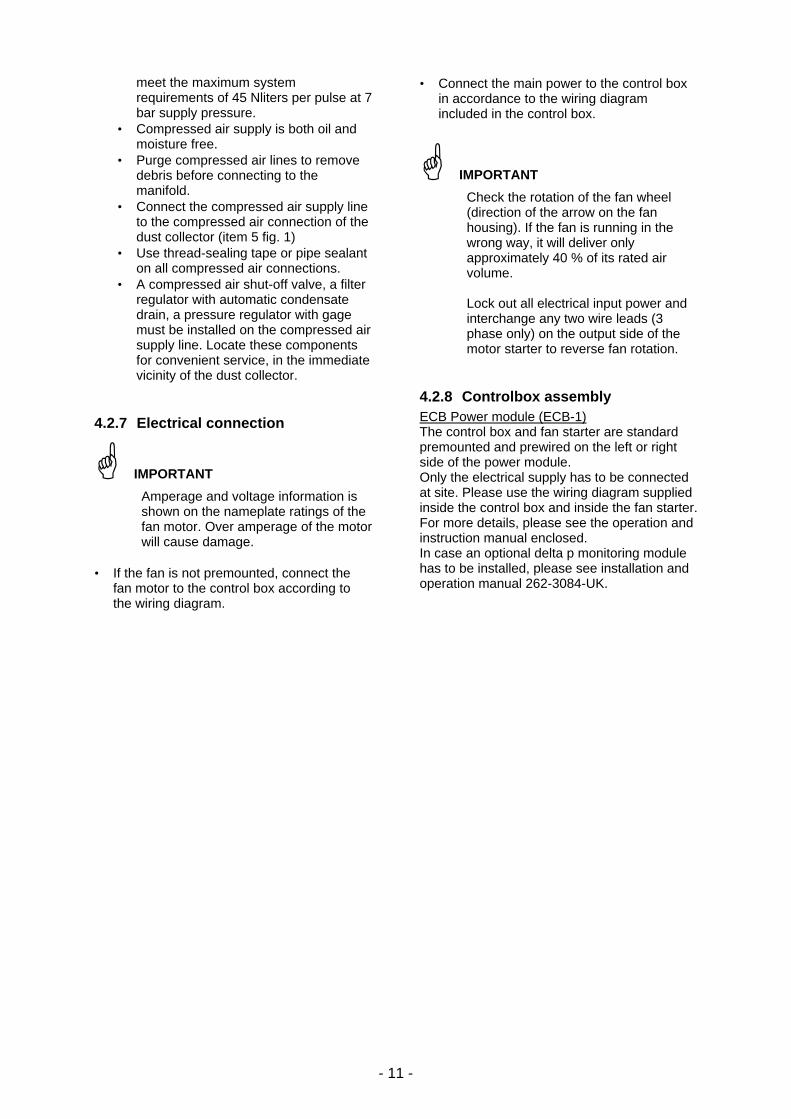
4.2.3.2 Optional Hepa filter - vertical flow Unscrew threaded rods from pressure frame and remove the pressure frame. Install Hepa filter with gasket positioned towards the bottom. Reinstall pressure frame and fasten the treaded rods by hand.
1. Threaded rod 2. Riv nut
3. Dust collector 4. Gasket Hepa filter element
5. Hepa filter 6. Pressure frame
Figure 8 : Installation of Hepa filter - vertical flow
4.2.4 In- and Outlets If not premounted, mount the in- and outlets as shown on the specific drawings.
4.2.4.1 Standard Open Louver Inlet This inlet has upward sloping louvers that reduce re-entrainment. It puts the bulk of the solids directly into the dust drawer, prolonges the filter life and reduces the pulsing frequency. This inlet is mounted with hinges above the dust drawers. Consequently, the drawers can be emptied without opening the louver cover.
4.2.4.2 Optional Self Closing Louver Inlet This inlet is similar to the open louver inlet, but has flexible panels attached to the inside of the louvers. These panels open when the fan is on and close when the fan is off. By pulsing with the fan off the user benefits from thorough pulse cleaning without blowing dust back into the work space. This inlet is mounted on hinges and must be opened to access the dust drawers.
CAUTION DO NOT USE WITH EXPLOSIVE DUST. This inlet should never be used in applications with an explosive particulate, such as finely divided wood dust or reactive metals. The standard open louver inlet should be installed in these applications.
4.2.4.3 Optional Spark Trap Inlet This inlet features a deflector design, which makes it very difficult for a live spark to enter the dirty air chamber. This inlet is not hinged and must be opened to access the dust drawers.
CAUTION This inlet should never be used in applications with an explosive particulate. It can, however, be used in applications with a flammable but non-explosive particulate, such as steel.
4.2.5 Control Box
⟨ NOTE The control box is factory mounted on the dust collector, according to our standards (except when specified by order).
CAUTION All the instructions related to the controls are mentioned in a separate manual (e.g. 262-3078-UK for F6).
4.2.6 Compressed Air Connection
G IMPORTANT
• Compressed air pressure must be between 6 and 7 bar.
• Be sure that all compressed air components are adequately sized to
- 11 -
meet the maximum system requirements of 45 Nliters per pulse at 7 bar supply pressure.
• Compressed air supply is both oil and moisture free.
• Purge compressed air lines to remove debris before connecting to the manifold.
• Connect the compressed air supply line to the compressed air connection of the dust collector (item 5 fig. 1)
• Use thread-sealing tape or pipe sealant on all compressed air connections.
• A compressed air shut-off valve, a filter regulator with automatic condensate drain, a pressure regulator with gage must be installed on the compressed air supply line. Locate these components for convenient service, in the immediate vicinity of the dust collector.
4.2.7 Electrical connection
G IMPORTANT
Amperage and voltage information is shown on the nameplate ratings of the fan motor. Over amperage of the motor will cause damage.
• If the fan is not premounted, connect the
fan motor to the control box according to the wiring diagram.
• Connect the main power to the control box in accordance to the wiring diagram included in the control box.
G IMPORTANT
Check the rotation of the fan wheel (direction of the arrow on the fan housing). If the fan is running in the wrong way, it will deliver only approximately 40 % of its rated air volume. Lock out all electrical input power and interchange any two wire leads (3 phase only) on the output side of the motor starter to reverse fan rotation.
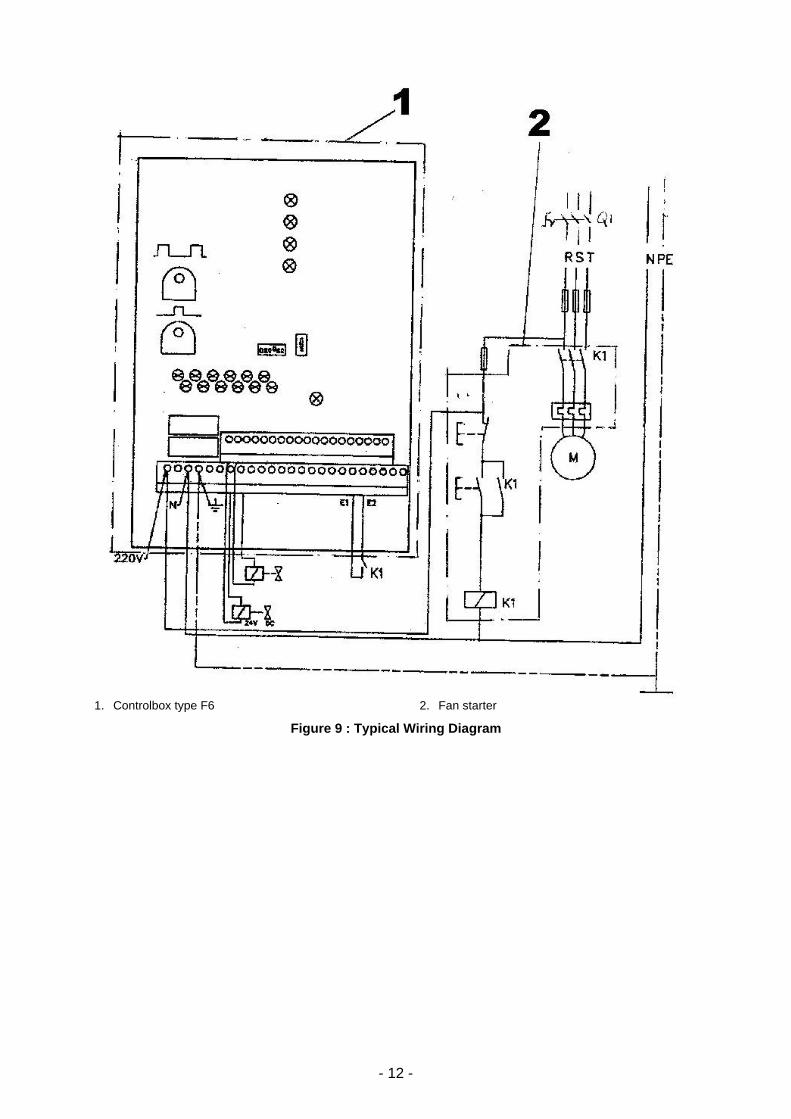
4.2.8 Controlbox assembly ECB Power module (ECB-1) The control box and fan starter are standard premounted and prewired on the left or right side of the power module. Only the electrical supply has to be connected at site. Please use the wiring diagram supplied inside the control box and inside the fan starter. For more details, please see the operation and instruction manual enclosed. In case an optional delta p monitoring module has to be installed, please see installation and operation manual 262-3084-UK.
- 12 -
1. Controlbox type F6 2. Fan starter
Figure 9 : Typical Wiring Diagram

- 13 -
Torit Control Board (TCB) for ECB-2, 3 and 4 and optional for ECB-1
1. Cable from solenoid valves 2. Electrical cable from fan motor (in case of
Star/Delta connection 2 cables are used).
3. Compressed air connection 4. Delta p connection - lower pressure side
Figure 10 : Top view (Utility connections)
• Connect all fan motor cables (1 per module)
to the corresponding terminals in the Torit Control Board (TCB) in accordance with the wiring diagram inside the Torit Control Board and in accordance with figure “Fan electrical connection”.
• Connect all multi wire cables (from solenoid
valves and 1 multi cable per module) to the corresponding terminals in the Torit Control Board. Note that each wire of the multi wire cable is numbered and prewired via a terminal board.
Drawing nr. Power Module 727-0137 ECB-2 727-0138 ECB-3 727-0139 ECB-4 727-0140
• Delta p connection: use the black tubing
(dia 6 mm) supplied with the unit to connect position 4 on figure Top View (Utility connections) with the nipple on the Torit Control Board.
1. Power module 2. TCB (Torit Control Board)
3. Pneumatic tubing (dia 4 mm internal) 4. Nipple for tube connection - delta p
Figure 11 : Delta P connection
- 14 -
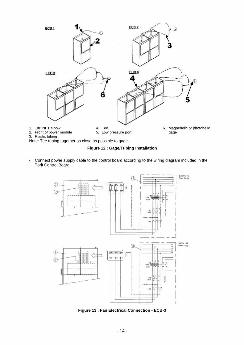
1. 1/8” NPT elbow 2. Front of power module 3. Plastic tubing
4. Tee 5. Low pressure port
6. Magnehelic or photohelic gage
Note: Tee tubing together as close as possible to gage.
Figure 12 : Gage/Tubing Installation
• Connect power supply cable to the control board according to the wiring diagram included in the
Torit Control Board.
Figure 13 : Fan Electrical Connection - ECB-3

- 15 -
For set-up of the different parameters (delta p max, min, downtime pulsing, etc...) other than pre-set by the factory and, also for explanation of the different functions on the Torit Control Board display please see OIM 262-3103-UK.
4.2.9 Light fixtures After the fixtures have been installed, wire them according to the wiring diagram included with the fixtures.
5. START-UP CHECKLIST
⟨ NOTE • Follow all steps before first start-up and
when the dust collector is not been used for a long period.
• For daily use follow steps 1, 2, 4, 5 and 7.
1. Check that the outlet of the fan is free of debris before starting.
2. Make sure the dust drawers are properly installed.
CAUTION Too much airflow can cause electrical failure of the fan motor or dramatically reduce the life of the filter elements.
3. Check if the access covers are closed. 4. Switch main power on and press ‘ON’. 5. Turn on the compressed air supply. Adjust
to 6.5 bar of pressure with the compressed air regulator.
CAUTION Do not increase compressed air pressure beyond 7 bar as component damage may result.
The cleaning cycle only starts when necessary. For customized settings see the control manual.
6. OPERATION SCHEDULE To ensure a good performance of your dust collector follow the checkpoints mentioned in the timetable.
No. Checkpoint Type of control Recommended action Day Weeks
2 4 8 26
1. Dust disposal system
Check contents of dust drawers
If ¾ full, empty dust drawer (see chapter 7.1)
X
2. Fan set Excessive noise See trouble shooting guide chapter 8
X
3. Clean air chamber
Emission : dust carry over in clean air chamber
See trouble shooting guide chapter 8
X
4. Controls settings
Check setting of both potentiometers (pulse time 100 milliseconds, interval time 10 seconds) on the control board (see separate manual)
Interval time normally to be set at 10 seconds. Pulse time 100 milliseconds.
X
5. Filter/regulator Oil and/or water is in the reservoir Switch off and bleed off compressed air prior servicing. Clean filter/regulator. Check compressor.
X
6. Diaphragm valves
Noise of escaping air is produced See trouble shooting guide chapter 8
X
7. Covers Visual check gaskets Replace gaskets if necessary
X
8. Dust collector and booth
Check damage, strength and corrosion
Repair or replace if necessary
X
9. Filter element Preventive replacement of all filter elements (see chapter 7.2)
Unless otherwise specified in the scope of delivery every 2 years.
- 16 -
7. SERVICE
CAUTION • Disconnect electrical power before
servicing. • Shut off and bleed off compressed air
supply before servicing any compressed air components.
• No welding should be performed inside without fire protection.
• Avoid contact or exposure to dust during servicing or maintenance.
7.1 Dust removal
G IMPORTANT
Do not let the dust drawer overfill. It can cause poor dust collector performance.
Turn off the dust collector and empty the dust drawers on a regular base (recommend to empty it when 3/4 full).
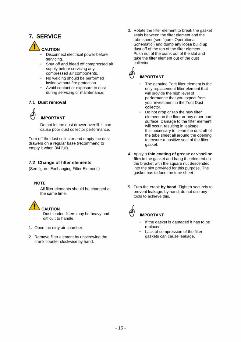
7.2 Change of filter elements (See figure ‘Exchanging Filter Element’)
⟨ NOTE All filter elements should be changed at the same time.
CAUTION Dust loaden filters may be heavy and difficult to handle.
1. Open the dirty air chamber. 2. Remove filter element by unscrewing the
crank counter clockwise by hand.
3. Rotate the filter element to break the gasket seals between the filter element and the tube sheet (see figure ‘Operational Schematic’) and dump any loose build up dust off of the top of the filter element. Push nut of the crank out of the slot and take the filter element out of the dust collector.
G IMPORTANT
• The genuine Torit filter element is the only replacement filter element that will provide the high level of performance that you expect from your investment in the Torit Dust collector.
• Do not drop or rap the new filter element on the floor or any other hard surface. Damage to the filter element will occur, resulting in leakage. It is necessary to clean the dust off of the tube sheet all around the opening to ensure a positive seal of the filter gasket.
4. Apply a thin coating of grease or vaseline
film to the gasket and hang the element on the bracket with the square nut descended into the slot provided for this purpose. The gasket has to face the tube sheet.
5. Turn the crank by hand. Tighten securely to
prevent leakage, by hand, do not use any tools to achieve this.
G IMPORTANT
• If the gasket is damaged it has to be replaced.
• Lack of compression of the filter gaskets can cause leakage.
- 17 -
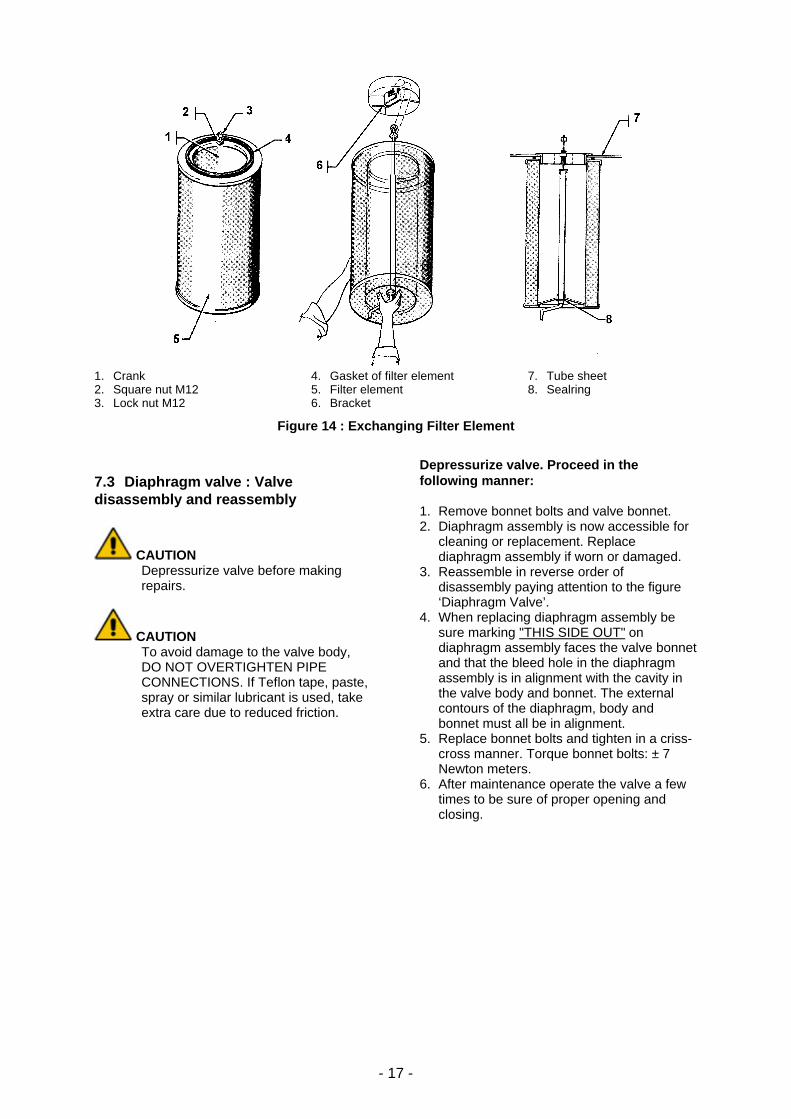
1. Crank 2. Square nut M12 3. Lock nut M12
4. Gasket of filter element 5. Filter element 6. Bracket
7. Tube sheet 8. Sealring
Figure 14 : Exchanging Filter Element
7.3 Diaphragm valve : Valve disassembly and reassembly
CAUTION Depressurize valve before making repairs.
CAUTION To avoid damage to the valve body, DO NOT OVERTIGHTEN PIPE CONNECTIONS. If Teflon tape, paste, spray or similar lubricant is used, take extra care due to reduced friction.
Depressurize valve. Proceed in the following manner: 1. Remove bonnet bolts and valve bonnet. 2. Diaphragm assembly is now accessible for
cleaning or replacement. Replace diaphragm assembly if worn or damaged.
3. Reassemble in reverse order of disassembly paying attention to the figure ‘Diaphragm Valve’.
4. When replacing diaphragm assembly be sure marking "THIS SIDE OUT" on diaphragm assembly faces the valve bonnet and that the bleed hole in the diaphragm assembly is in alignment with the cavity in the valve body and bonnet. The external contours of the diaphragm, body and bonnet must all be in alignment.
5. Replace bonnet bolts and tighten in a criss-cross manner. Torque bonnet bolts: ± 7 Newton meters.
6. After maintenance operate the valve a few times to be sure of proper opening and closing.
- 18 -
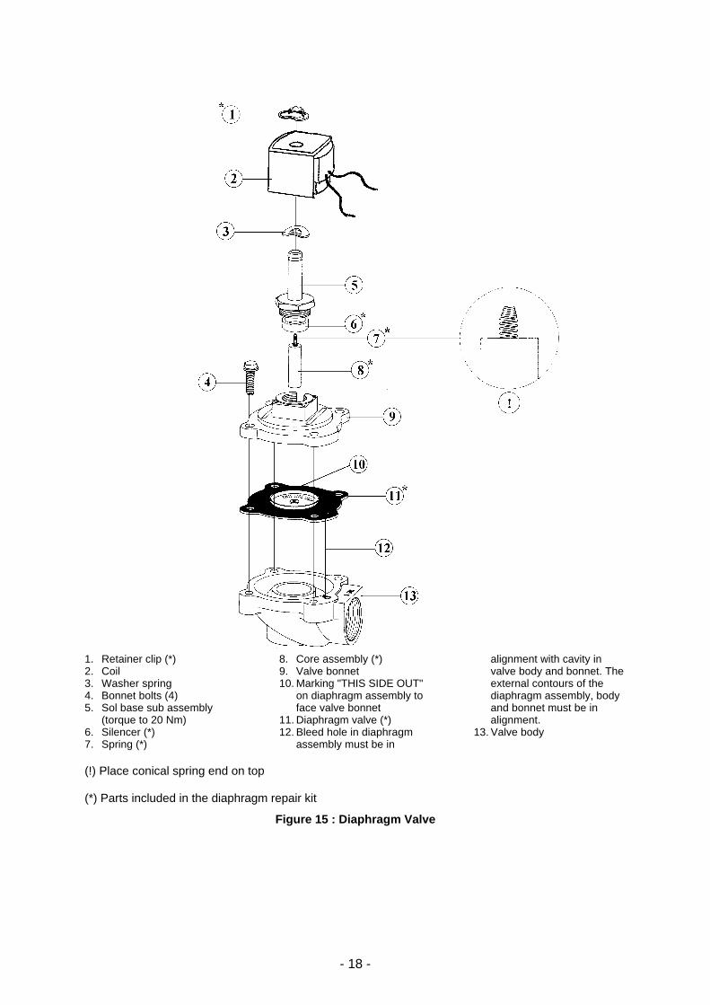
1. Retainer clip (*) 2. Coil 3. Washer spring 4. Bonnet bolts (4) 5. Sol base sub assembly
(torque to 20 Nm) 6. Silencer (*) 7. Spring (*)
8. Core assembly (*) 9. Valve bonnet 10. Marking "THIS SIDE OUT"
on diaphragm assembly to face valve bonnet
11. Diaphragm valve (*) 12. Bleed hole in diaphragm
assembly must be in
alignment with cavity in valve body and bonnet. The external contours of the diaphragm assembly, body and bonnet must be in alignment.
13. Valve body
(!) Place conical spring end on top (*) Parts included in the diaphragm repair kit
Figure 15 : Diaphragm Valve
- 19 -
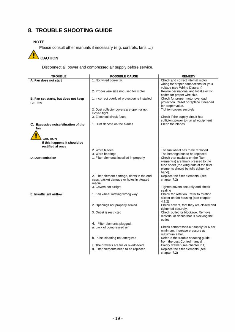
8. TROUBLE SHOOTING GUIDE
⟨ NOTE Please consult other manuals if necessary (e.g. controls, fans,…)
CAUTION
Disconnect all power and compressed air supply before service.
TROUBLE POSSIBLE CAUSE REMEDY A. Fan does not start 1. Not wired correctly. Check and correct internal motor
wiring for proper connections for your voltage (see Wiring Diagram)
2. Proper wire size not used for motor Rewire per national and local electric codes for proper wire size.
B. Fan set starts, but does not keep running
1. Incorrect overload protection is installed Check for proper motor overload protection. Reset or replace if needed for proper value.
2. Dust collector covers are open or not closed tight
Tighten covers securely
3. Electrical circuit fuses Check if the supply circuit has sufficient power to run all equipment
C. Excessive noise/vibration of the fan
CAUTION If this happens it should be rectified at once
1. Dust deposit on the blades Clean the blades
2. Worn blades The fan wheel has to be replaced 3. Worn bearings The bearings has to be replaced D. Dust emission 1. Filter elements installed improperly Check that gaskets on the filter
element(s) are firmly pressed to the tube sheet (the wing nuts of the filter elements should be fully tighten by hand).
2. Filter element damage, dents in the end caps, gasket damage or holes in pleated media
Replace the filter elements. (see chapter 7.2)
3. Covers not airtight Tighten covers securely and check sealing
E. Insufficient airflow 1. Fan wheel rotating wrong way Check fan rotation. Refer to rotation sticker on fan housing (see chapter 4.2.2)
2. Openings not properly sealed Check covers, that they are closed and tightened securely.
3. Outlet is restricted Check outlet for blockage. Remove material or debris that is blocking the outlet.
4. Filter elements plugged : a. Lack of compressed air
Check compressed air supply for 6 bar minimum. Increase pressure at maximum 7 bar.
b. Pulse cleaning not energized Refer to the trouble shooting guide from the dust Control manual
c. The drawers are full or overloaded Empty drawer (see chapter 7.1) d. Filter elements need to be replaced Replace the filter elements (see
chapter 7.2)
- 20 -
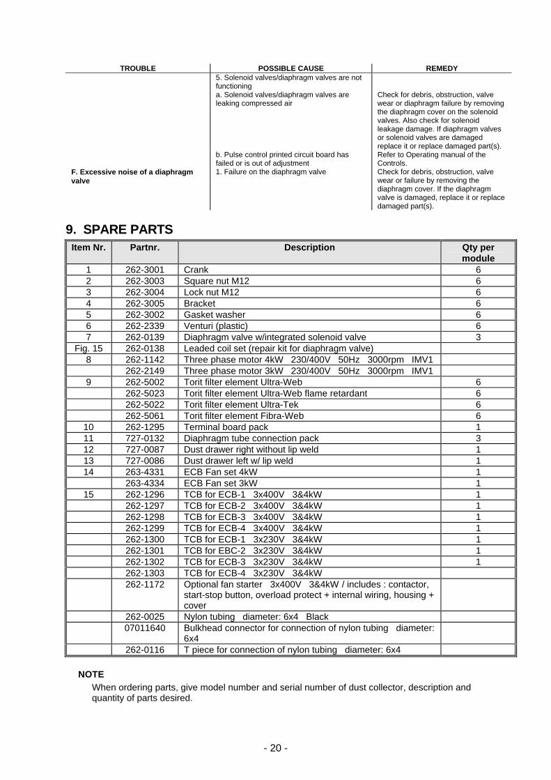
TROUBLE POSSIBLE CAUSE REMEDY
5. Solenoid valves/diaphragm valves are not functioning
a. Solenoid valves/diaphragm valves are leaking compressed air
Check for debris, obstruction, valve wear or diaphragm failure by removing the diaphragm cover on the solenoid valves. Also check for solenoid leakage damage. If diaphragm valves or solenoid valves are damaged replace it or replace damaged part(s).
b. Pulse control printed circuit board has failed or is out of adjustment
Refer to Operating manual of the Controls.
F. Excessive noise of a diaphragm valve
1. Failure on the diaphragm valve Check for debris, obstruction, valve wear or failure by removing the diaphragm cover. If the diaphragm valve is damaged, replace it or replace damaged part(s).
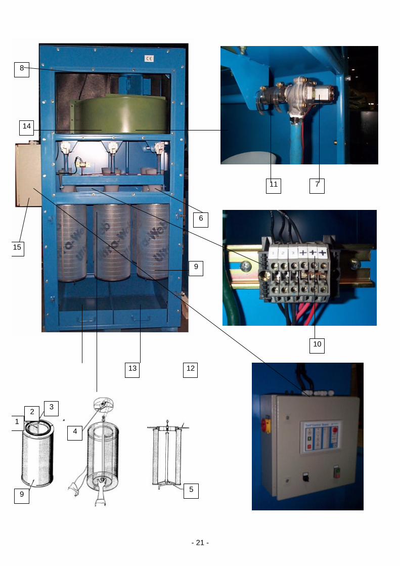
9. SPARE PARTS Item Nr. Partnr. Description Qty per
module 1 262-3001 Crank 6 2 262-3003 Square nut M12 6 3 262-3004 Lock nut M12 6 4 262-3005 Bracket 6 5 262-3002 Gasket washer 6 6 262-2339 Venturi (plastic) 6 7 262-0139 Diaphragm valve w/integrated solenoid valve 3
Fig. 15 262-0138 Leaded coil set (repair kit for diaphragm valve) 8 262-1142 Three phase motor 4kW 230/400V 50Hz 3000rpm IMV1 262-2149 Three phase motor 3kW 230/400V 50Hz 3000rpm IMV1 9 262-5002 Torit filter element Ultra-Web 6 262-5023 Torit filter element Ultra-Web flame retardant 6 262-5022 Torit filter element Ultra-Tek 6 262-5061 Torit filter element Fibra-Web 6
10 262-1295 Terminal board pack 1 11 727-0132 Diaphragm tube connection pack 3 12 727-0087 Dust drawer right without lip weld 1 13 727-0086 Dust drawer left w/ lip weld 1 14 263-4331 ECB Fan set 4kW 1 263-4334 ECB Fan set 3kW 1
15 262-1296 TCB for ECB-1 3x400V 3&4kW 1 262-1297 TCB for ECB-2 3x400V 3&4kW 1 262-1298 TCB for ECB-3 3x400V 3&4kW 1 262-1299 TCB for ECB-4 3x400V 3&4kW 1 262-1300 TCB for ECB-1 3x230V 3&4kW 1 262-1301 TCB for EBC-2 3x230V 3&4kW 1 262-1302 TCB for ECB-3 3x230V 3&4kW 1 262-1303 TCB for ECB-4 3x230V 3&4kW 262-1172 Optional fan starter 3x400V 3&4kW / includes : contactor,
start-stop button, overload protect + internal wiring, housing + cover
262-0025 Nylon tubing diameter: 6x4 Black 07011640 Bulkhead connector for connection of nylon tubing diameter:
6x4
262-0116 T piece for connection of nylon tubing diameter: 6x4
⟨ NOTE When ordering parts, give model number and serial number of dust collector, description and quantity of parts desired.
- 21 -
8
14
15
6
9
11 7
13 12
10
5 9
1
3 2
4
- 22 -
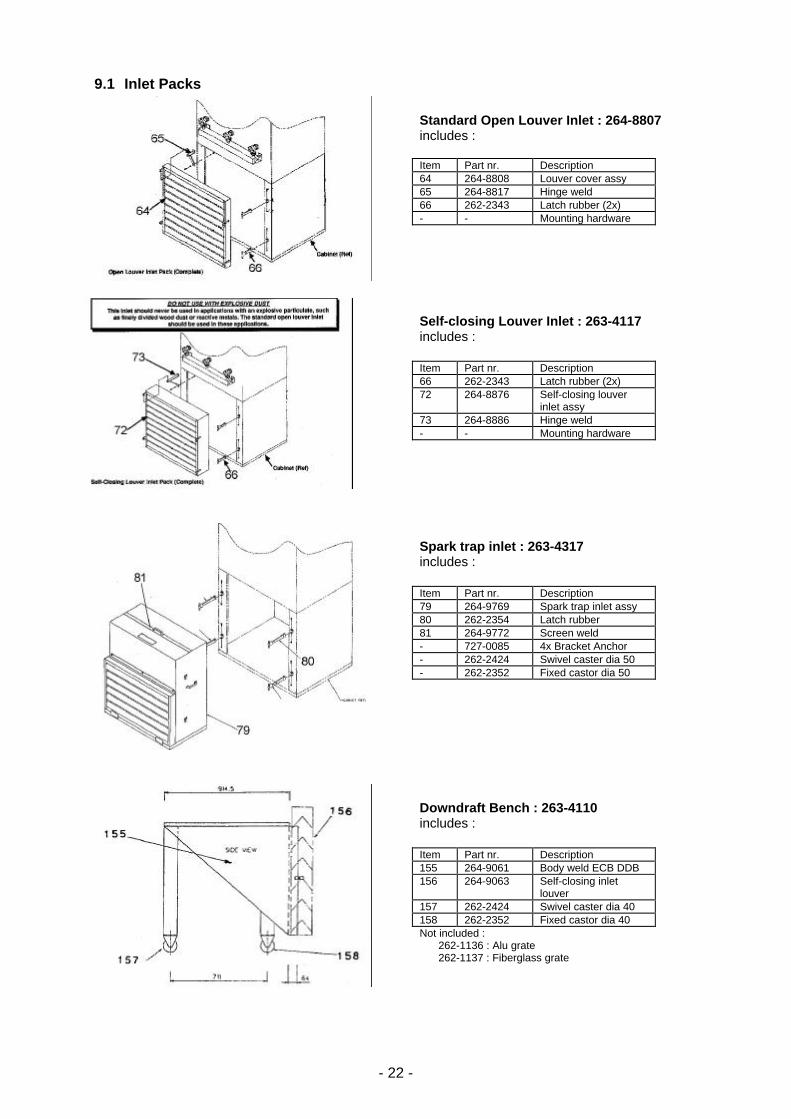
9.1 Inlet Packs
Standard Open Louver Inlet : 264-8807 includes : Item Part nr. Description 64 264-8808 Louver cover assy 65 264-8817 Hinge weld 66 262-2343 Latch rubber (2x) - - Mounting hardware
Self-closing Louver Inlet : 263-4117 includes : Item Part nr. Description 66 262-2343 Latch rubber (2x) 72 264-8876 Self-closing louver
inlet assy 73 264-8886 Hinge weld - - Mounting hardware
Spark trap inlet : 263-4317 includes : Item Part nr. Description 79 264-9769 Spark trap inlet assy 80 262-2354 Latch rubber 81 264-9772 Screen weld - 727-0085 4x Bracket Anchor - 262-2424 Swivel caster dia 50 - 262-2352 Fixed castor dia 50
Downdraft Bench : 263-4110 includes : Item Part nr. Description 155 264-9061 Body weld ECB DDB 156 264-9063 Self-closing inlet
louver 157 262-2424 Swivel caster dia 40 158 262-2352 Fixed castor dia 40 Not included : 262-1136 : Alu grate 262-1137 : Fiberglass grate
- 23 -
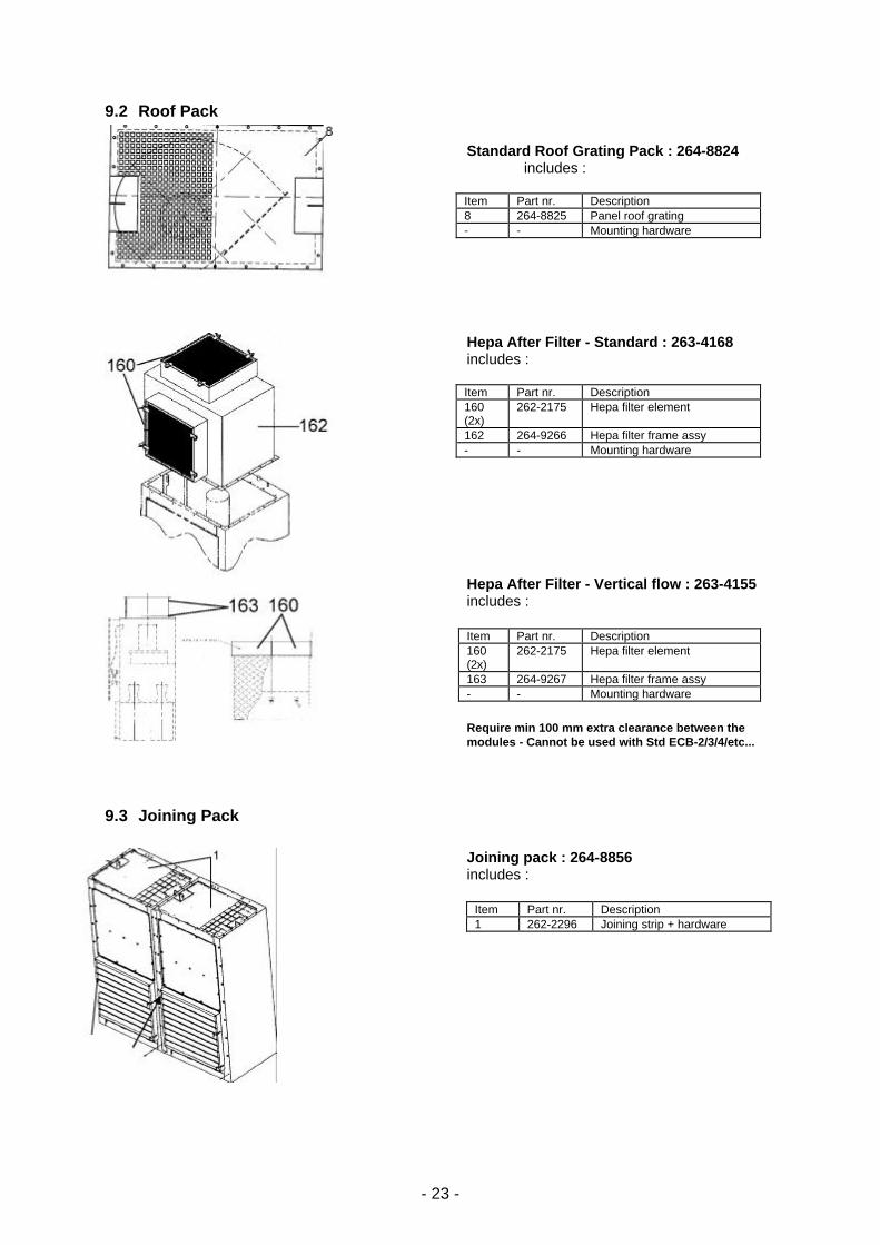
9.2 Roof Pack
Standard Roof Grating Pack : 264-8824 includes : Item Part nr. Description 8 264-8825 Panel roof grating - - Mounting hardware
Hepa After Filter - Standard : 263-4168 includes : Item Part nr. Description 160 (2x)
262-2175 Hepa filter element
162 264-9266 Hepa filter frame assy - - Mounting hardware
Hepa After Filter - Vertical flow : 263-4155 includes : Item Part nr. Description 160 (2x)
262-2175 Hepa filter element
163 264-9267 Hepa filter frame assy - - Mounting hardware
Require min 100 mm extra clearance between the modules - Cannot be used with Std ECB-2/3/4/etc...
9.3 Joining Pack
Joining pack : 264-8856 includes :
Item Part nr. Description 1 262-2296 Joining strip + hardware
- 24 -
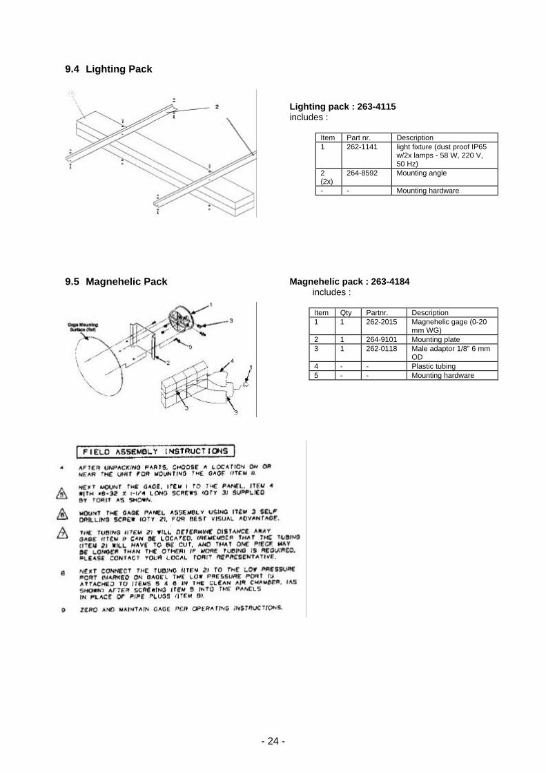
9.4 Lighting Pack
Lighting pack : 263-4115 includes :
Item Part nr. Description 1 262-1141 light fixture (dust proof IP65
w/2x lamps - 58 W, 220 V, 50 Hz)
2 (2x)
264-8592 Mounting angle
- - Mounting hardware
9.5 Magnehelic Pack
Magnehelic pack : 263-4184 includes :
Item Qty Partnr. Description 1 1 262-2015 Magnehelic gage (0-20
mm WG) 2 1 264-9101 Mounting plate 3 1 262-0118 Male adaptor 1/8” 6 mm
OD 4 - - Plastic tubing 5 - - Mounting hardware
- 25 -
10. CONTACT ADDRESSES Donaldson Europe N.V. Torit Products Interleuvenlaan 1 B - 3001 Leuven (Heverlee) Belgium Tel.(gen) : (016)383 811 Tel.(sales) : (016) 383 970 Fax (016) 383 938
Donaldson Torit b.v. Torit Products Postbus 770 NL - 2003 RT Haarlem Nederland Tel. 023-5319 099 Fax 023-5328 343
Donaldson Filter Components Ltd. Torit Products 65, Market Street Hednesford Staffordshire WS12 5AD United Kingdom Tel. 01543-870 710 Fax 01543-870 719
Donaldson GmbH Torit Products Industriestrasse 11 D - 48249 Dülmen Deutschland Tel. 02594-78 141 Fax 02594-78 189
Donaldson France S.A. Torit Products 4 bis, rue Maryse-Bastié F - 69500 Bron France Tél. 04.72.14.18.46 Fax 04.78.26.77.56
Donaldson Italia s.r.l. Torit Products Z.I. Strada A, 17 I - 46035 Ostiglia (MN) Italia Tel. 0386-302 183 Fax 0386-800 463
Donaldson Filtros Ibérica, S.L. Parque Empresarial San Fernando Avda. Castilla, No. 2 Edificio Dublin E - 28831 San Fernando de Heneres (Madrid) España Tel. 91 677 15 85 Fax 91 676 87 62
e-mail : [email protected]

- 26 -
11. CE DECLARATION
UK
EC DECLARATION OF CONFORMITY (Machinery directives 98/37/EEC)
Manufacturer : Donaldson® Europe N.V. Interleuvenlaan 1 - B-3001 Leuven, Belgium Description of the machinery : Dust Collector Brand : Donaldson® ?Torit® Type : ECB Description : see attached scope of delivery The undersigned, authorized by Donaldson Europe NV, certifies that the machine described above, provided that it is installed, maintained and used in accordance with the instructions for use and the codes of practice, meets the essential safety and health requirements of the "machinery" Directive and the following stipulations and standards : − Machinery directives 98/37/EEC − Low voltage directive 73/23/EEC − EN 60204-1 (ed. Oct. 92) safety of machinery. Electrical equipment of machines - General requirements − Pressure equipment directive (97/23/EC) − Electromagnetic compatibility Directive 89/336/EEC And the essential principles of the following standards − EN292-1/-2 (ed. Sept 91) Safety of Machinery − EN294 (ed. Jan.93) Safety of Machinery - Safety distances to prevent danger zones being reached by upper limbs. − pr EN626-1 (ed. Jan94)/-2 (ed. Mar94) Safety of Machinery reduction or elimination of risks to health from hazardous substances emitted by Machinery. IMPORTANT ! Read the Operation and Instruction Manual before using this machine. If you require additional copies contact your local Donaldson Torit representative. The machinery must not be put into service until the machinery into which it is to be incorporated has been declared in conformity with the provisions of the above mentioned directives.
Signature : Date : 02 June 2004 Name : Jos Dottermans Position : Director Torit Europe