Embed Size (px)
Citation preview
© Autarco Group B.V. IM-S2-XLX-EN-V1.4
Installation and Operation Manual
Solar Inverters XLX-series
2 XLX-series Inverters
Contact Information Autarco Group B.V. Schansoord 60 5469 DT Erp The Netherlands www.autarco.com [email protected] Other Information This manual is an integral part of the unit. Please read the manual carefully before installation, operation or maintenance. Keep this manual for future reference. Product information is subject to change without notice. All trademarks are recognized as the property of their respective owners. © Autarco Group B.V. All rights reserved.
installation and operation manual
IM-S2-XLX-EN-V1.4 3
Table of Contents 1. Introduction ....................................................................................................................................... 4 1.1 Read this first ............................................................................................................................................... 4 1.2 Target Audience .......................................................................................................................................... 4 1.3 Product versions covered by this document ............................................................................................... 5 2. Preparation ........................................................................................................................................ 6 2.1 Safety instructions ....................................................................................................................................... 6 2.2 Package contents ......................................................................................................................................... 7 2.3 Internal DC switch ....................................................................................................................................... 7 2.4 Explanations of symbols on inverter ........................................................................................................... 7 3. Product information ........................................................................................................................... 8 3.1 Overview ...................................................................................................................................................... 8 3.2 Product identification .................................................................................................................................. 8 3.3 Product overview......................................................................................................................................... 9 4. Installation ....................................................................................................................................... 10 4.1 Safety ......................................................................................................................................................... 10 4.2 Mounting instructions ............................................................................................................................... 10 4.3 Safety clearance ........................................................................................................................................ 11 4.4 Mounting procedure ................................................................................................................................. 12 5. Electrical installation ........................................................................................................................ 14 5.1 AC connection ............................................................................................................................................ 14 5.2 DC connections .......................................................................................................................................... 16 5.3 Commissioning and Decommisioning sequence ....................................................................................... 17 6. Operation......................................................................................................................................... 18 6.1 LED indicator lights .................................................................................................................................... 18 6.2 Inverter display .......................................................................................................................................... 18 6.3 Information ................................................................................................................................................ 19 6.4 Settings ...................................................................................................................................................... 20 6.5 Advanced info ............................................................................................................................................ 20 6.6 Advanced Settings ..................................................................................................................................... 21 7. Monitoring setup and system registration ......................................................................................... 22 8. Maintenance .................................................................................................................................... 22 9. Disposal ........................................................................................................................................... 22 10. Troubleshooting ............................................................................................................................... 23 10.1 General ...................................................................................................................................................... 23 10.2 Internal component fault .......................................................................................................................... 23 10.3 Grid errors ................................................................................................................................................. 24 10.4 System and design fault............................................................................................................................. 25 11. Product specifications ....................................................................................................................... 26
4 XLX-series Inverters
1. Introduction
1.1 Read this first This manual contains important information for use during installation and maintenance of the XLX-series Autarco inverter. To reduce the risk of electrical shock, and to ensure the safe installation and operation of the XLX-series Autarco inverters, the following safety symbols appear throughout this document to indicate dangerous conditions and important safety instructions.
WARNING! Indicates safety instruction, which if not correctly followed, can result in injury or property damages.
RISK OF ELECTRIC SHOCK! Indicates safety instructions, which if not correctly followed, could result in electric shock.
HOT SURFACE! Indicates safety instructions, which if not correctly followed, could result in burns.
1.2 Target Audience This manual is intended for anyone who uses Autarco XLX-series inverter. Before any further action, the operators must first read all safety regulations and be aware of the potential danger to operate high-voltage devices. Operators must also have a complete understanding of this device’s features and functions.
ATTENTION! Qualified personnel means a person with valid license from the local authority in:
Installing electrical equipment and PV power systems (up to 1000 V).
Applying all applicable installation codes and using Personal Protective Equipment.
Analyzing and reducing the hazards involved in performing electrical work.
WARNING! Do not use this product unless it has been successfully installed by qualified personnel in accordance with the instructions in chapter 4 “Installation”.
installation and operation manual
IM-S2-XLX-EN-V1.4 5
1.3 Product versions covered by this document The main purpose of this user manual is to provide instructions and detailed procedures for installing, operating,
maintaining, and troubleshooting the XLX-series of Autarco inverters which includes the following models:
For 380/400V AC grid connection:
S2.XLX20000(S)
S2.XLX25000(S)
S2.XLX30000(S)
S2.XLX30000-HE(S)
For 480V AC grid connection:
S2.XLX36000–HV(S)
The “S2.” In the product code means the product is a grid-tied inverter. If the product has an “S” at the end it
comes with integrated DC switches.
The item code or SKU will include an additional number at the end. The final number references the default grid
standard and colour of inverter. For example, S2.XLX20000S.1 is the 20kW model with Dutch grid standard as
default, integrated DC switch and Autarco blue cover.
Please keep this user manual available at all times in case of emergency.
6 XLX-series Inverters
2. Preparation
2.1 Safety instructions
DANGER! Do not touch any internal components whilst the inverter is in operation.
DANGER! Do not stand close to the inverter during severe weather conditions such as lighting,
etc.
Make sure you completely cover the surface of all PV arrays with opaque (dark) material before
wiring them or make sure the DC circuit breaker or equivalent DC isolator is disconnected.
This is because photovoltaic (PV) arrays create electrical energy when exposed to light, and could
cause a hazardous condition.
The XLX series inverter must only be operated with PV arrays of protection class II, in accordance with IEC 61730, class A.
WARNING! The PV inverter will become hot during operation; please don’t touch the heat sink or peripheral surface during or shortly after operation.
NOTICE! Do not directly connect AC output of the inverter to any private AC equipment. The PV inverter is designed to feed AC power directly into the public utility power grid.
WARNING! The installation, service, recycling and disposal of the inverters must be performed by
qualified personnel in compliance with national and local standards and regulations.
Please contact your dealer to get the information of authorized repair facility for any
maintenance or repairmen.
Any unauthorized actions including modification of product functionality of any form will affect the validation of warranty service; Autarco may deny the obligation of warranty service accordingly.
installation and operation manual
IM-S2-XLX-EN-V1.4 7
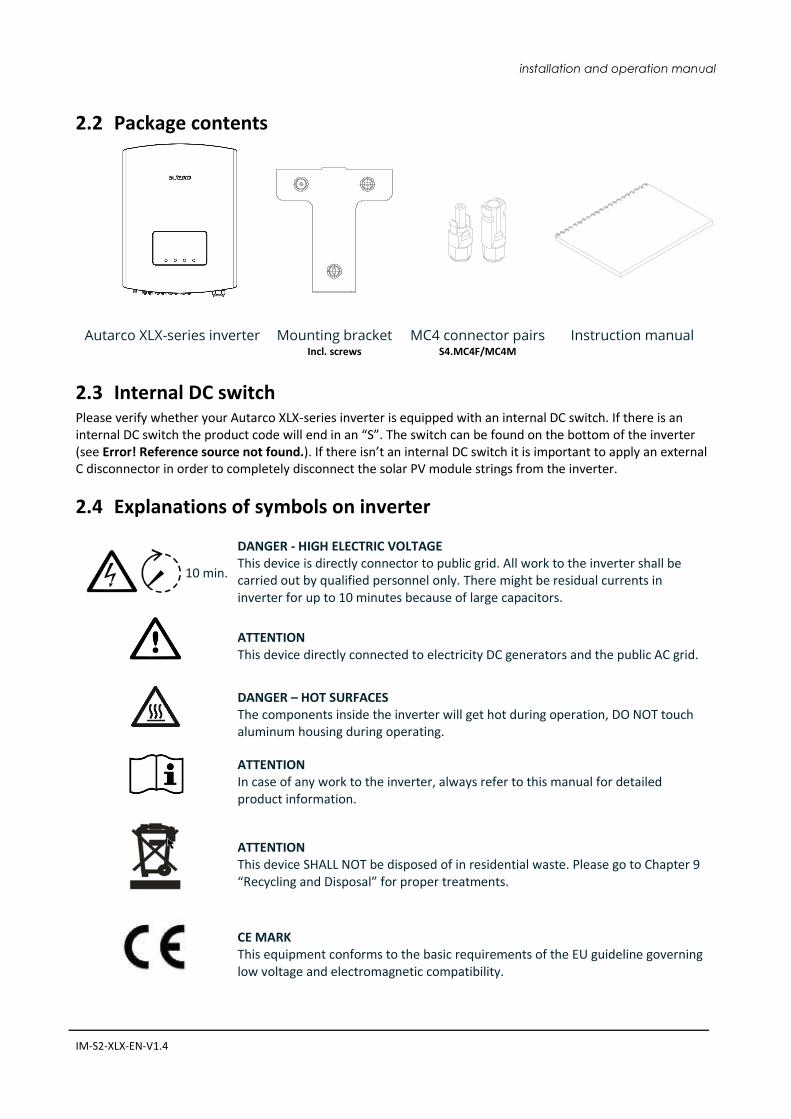
2.2 Package contents
Autarco XLX-series inverter Mounting bracket Incl. screws
MC4 connector pairs S4.MC4F/MC4M
Instruction manual
2.3 Internal DC switch Please verify whether your Autarco XLX-series inverter is equipped with an internal DC switch. If there is an internal DC switch the product code will end in an “S”. The switch can be found on the bottom of the inverter (see Error! Reference source not found.). If there isn’t an internal DC switch it is important to apply an external C disconnector in order to completely disconnect the solar PV module strings from the inverter.
2.4 Explanations of symbols on inverter
10 min.
DANGER - HIGH ELECTRIC VOLTAGE This device is directly connector to public grid. All work to the inverter shall be carried out by qualified personnel only. There might be residual currents in inverter for up to 10 minutes because of large capacitors.
ATTENTION This device directly connected to electricity DC generators and the public AC grid.
DANGER – HOT SURFACES The components inside the inverter will get hot during operation, DO NOT touch aluminum housing during operating.
ATTENTION In case of any work to the inverter, always refer to this manual for detailed product information.
ATTENTION This device SHALL NOT be disposed of in residential waste. Please go to Chapter 9 “Recycling and Disposal” for proper treatments.
CE MARK This equipment conforms to the basic requirements of the EU guideline governing low voltage and electromagnetic compatibility.
8 XLX-series Inverters
3. Product information
3.1 Overview Autarco XLX-series grid tied inverters are state of the art, high efficiency, robust and reliable grid tied inverters at the best price quality ratio available. They are easy to install and carry a standard 10 year product warranty. Our rigorous quality control and testing facilities guarantee Autarco inverters meet the highest quality standards possible. These inverters are the key to our international track record of delivering extremely reliable solar power solutions. Key features:
Maximum efficiency of 98.4%
7” LCD colour display
4 MPPT with wide voltage range
Low turn off voltage
High enclosure protection class IP65
Silent design using convection cooling principle
Standard ten year product warranty
Standard with wireless monitoring
Optional integrated DC switch
High range of protective functions
For full specifications please see chapter 11 “Product specifications”.
3.2 Product identification You can identify the inverter by the serial number (S/N) sticker on the side of the inverter. Important electrical specification can also be found on the label which can be found on the right side of the inverter housing. Do not remove the label or the serial number as this voids the product warranty.
installation and operation manual
IM-S2-XLX-EN-V1.4 9
3.3 Product overview
E
B C D
F G H I
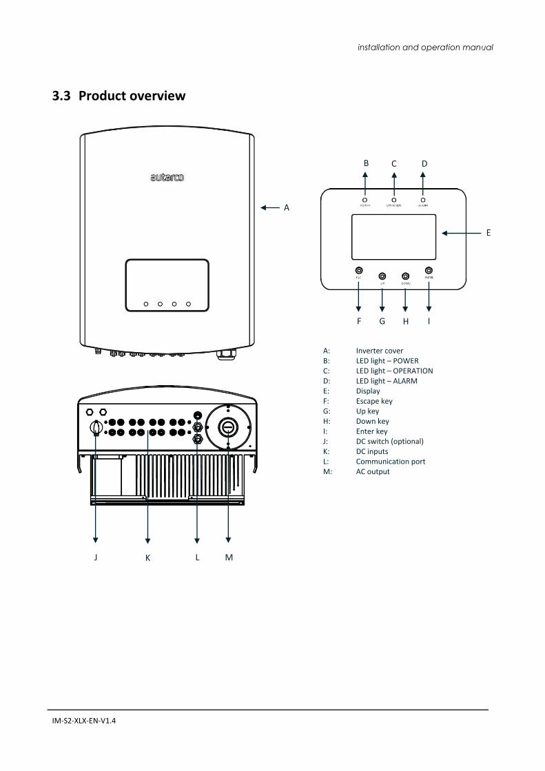
A: Inverter cover B: LED light – POWER C: LED light – OPERATION D: LED light – ALARM E: Display F: Escape key G: Up key H: Down key I: Enter key J: DC switch (optional) K: DC inputs L: Communication port M: AC output
A
K L M J
10 XLX-series Inverters
4. Installation
4.1 Safety
DANGER! Do not install the inverter near flammable or explosive items.
WARNING! The installation must be performed by qualified personnel and in compliance with national and local standards and regulations. This inverter will be connected to a high voltage DC power generator and AC grid. Inappropriate installation may also jeopardize the life span of the inverter.
The installation site must have good ventilation conditions. Direct exposure to intense sunshine is not recommended.
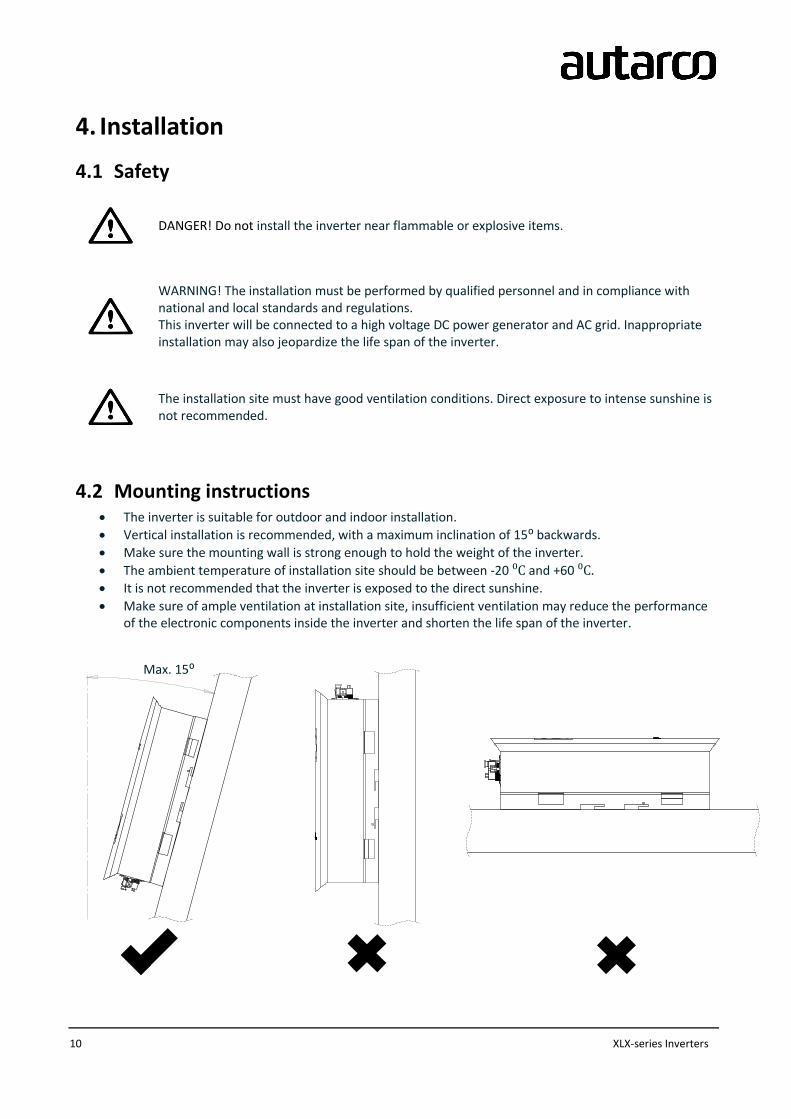
4.2 Mounting instructions The inverter is suitable for outdoor and indoor installation.
Vertical installation is recommended, with a maximum inclination of 15⁰ backwards.
Make sure the mounting wall is strong enough to hold the weight of the inverter.
The ambient temperature of installation site should be between -20 ⁰C and +60 ⁰C.
It is not recommended that the inverter is exposed to the direct sunshine.
Make sure of ample ventilation at installation site, insufficient ventilation may reduce the performance of the electronic components inside the inverter and shorten the life span of the inverter.
Max. 15⁰
installation and operation manual
IM-S2-XLX-EN-V1.4 11
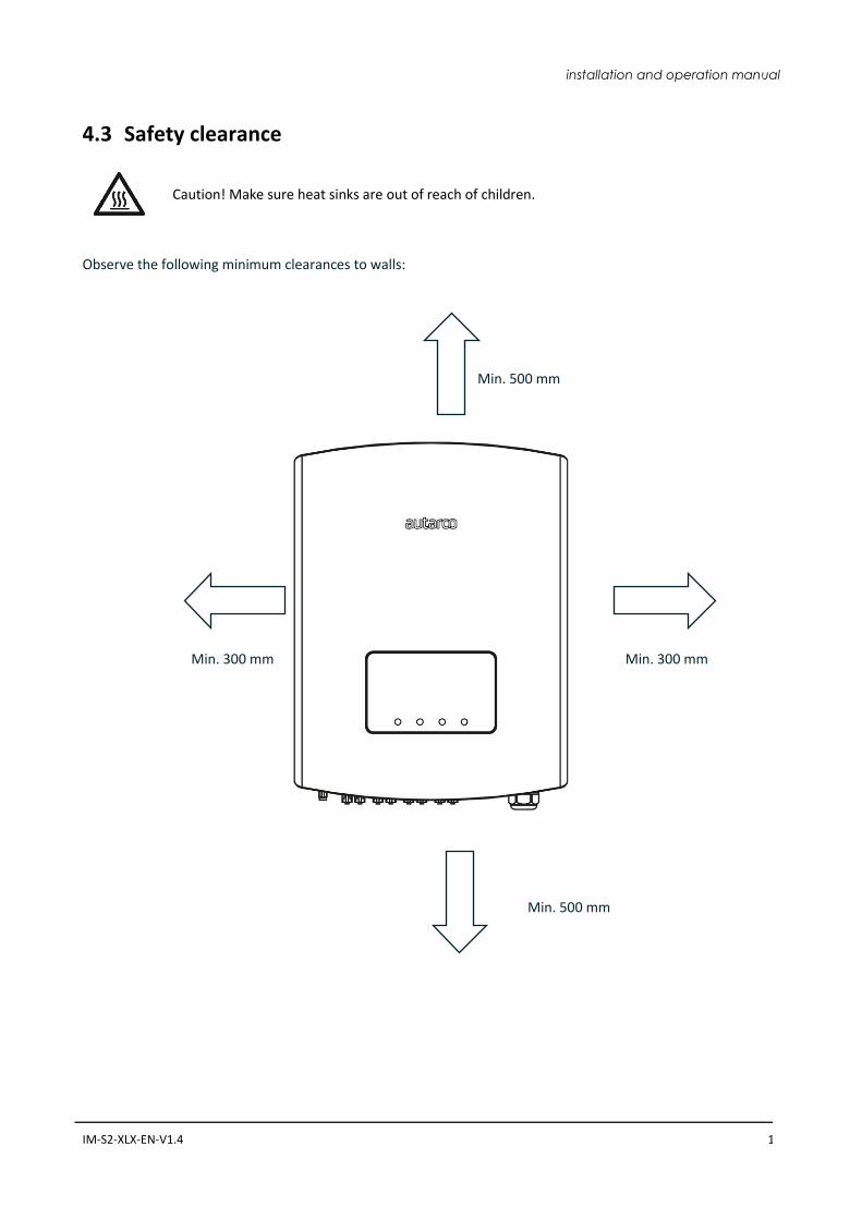
4.3 Safety clearance
Caution! Make sure heat sinks are out of reach of children.
Observe the following minimum clearances to walls:
Min. 300 mm Min. 300 mm
Min. 500 mm
Min. 500 mm
12 XLX-series Inverters
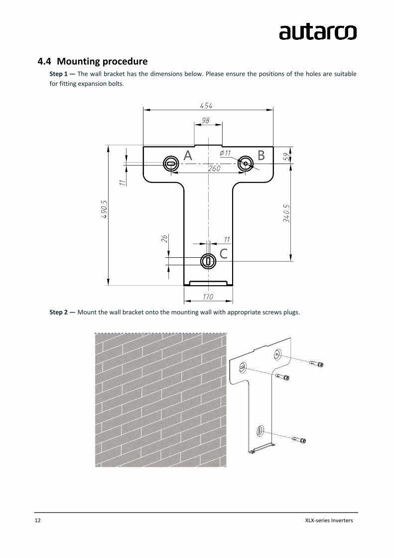
4.4 Mounting procedure Step 1 — The wall bracket has the dimensions below. Please ensure the positions of the holes are suitable
for fitting expansion bolts.
Step 2 — Mount the wall bracket onto the mounting wall with appropriate screws plugs.
installation and operation manual
IM-S2-XLX-EN-V1.4 13
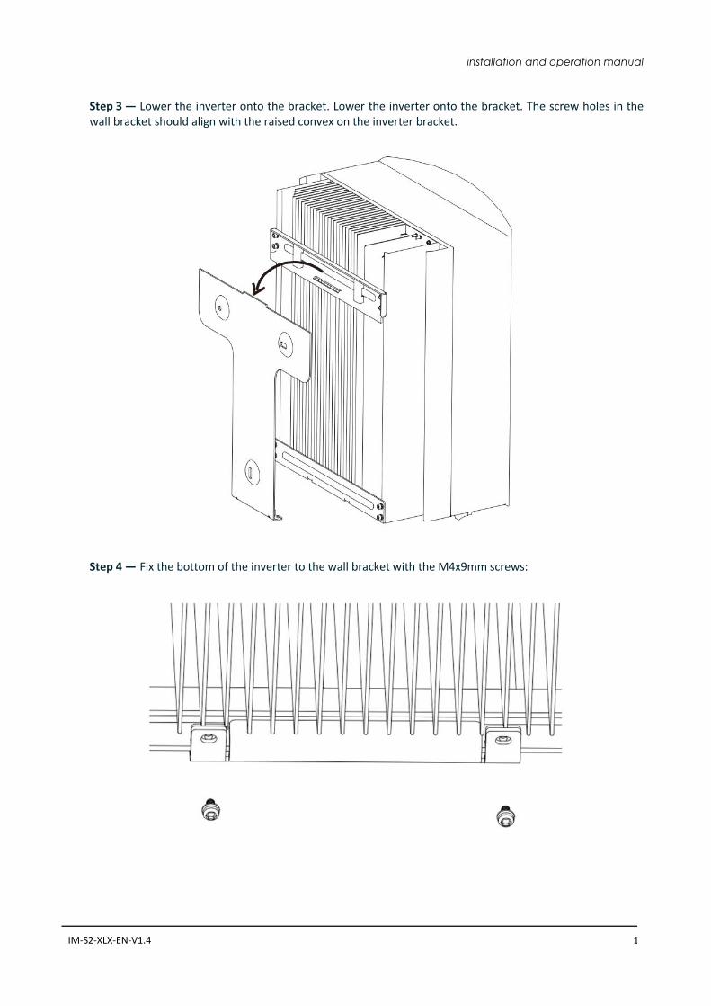
Step 3 — Lower the inverter onto the bracket. Lower the inverter onto the bracket. The screw holes in the wall bracket should align with the raised convex on the inverter bracket.
Step 4 — Fix the bottom of the inverter to the wall bracket with the M4x9mm screws:
14 XLX-series Inverters
5. Electrical installation
DANGER! This inverter will be connected to a high voltage DC power generator and AC grid. The installation must be performed by qualified personnel and in compliance with national and local standards and regulations
5.1 AC connection
DANGER! Never connect or disconnect the connectors under load.
NOTICE! The AC connection to the electrical distribution grid must be performed only after receiving authorization from the utility that operates the grid.
NOTICE! Make sure to set the correct grid standard as part of system commissioning, see chapeter 6.6.
The Autarco inverter is equipped with an integrated Residual Current Protective Device (RCPD) and Residual Current Operated Monitor (RCOM). The RCOM will detect the volume of the leakage current and compare it with the expected value, if the leakage current exceeds the permitted range, the RCPD will disconnect the inverter from the AC load. If regulations in the country of installation stipulate an external Residual Current Device (RCD), you must use a device with a tripping threshold of 100 mA or more. A type “A” RCD can be used in accordance with our “Manufacturer’s declaration for usage of residual current devices with Autarco SX, MX, LX and XLX grid-tied inverters.” The AC cable used must be dimensioned in accordance with any local and national directives on cable dimensions which specify requirements for the minimum conductor cross-section. Cable dimensioning factors are e.g.: nominal AC current, type of cable, type of routing, cable bundling, ambient temperature and maximum specified line losses. We recommend 10-35mm 105˚C cable with resistance lower than 1.5 ohm. If cable is longer than 100m, we recommend to use 16-35mm cable.
installation and operation manual
IM-S2-XLX-EN-V1.4 15
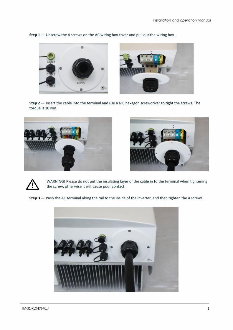
Step 1 — Unscrew the 4 screws on the AC wiring box cover and pull out the wiring box.
Step 2 — Insert the cable into the terminal and use a M6 hexagon screwdriver to tight the screws. The torque is 10 Nm.
WARNING! Please do not put the insulating layer of the cable in to the terminal when tightening the screw, otherwise it will cause poor contact.
Step 3 — Push the AC terminal along the rail to the inside of the inverter, and then tighten the 4 screws.
16 XLX-series Inverters
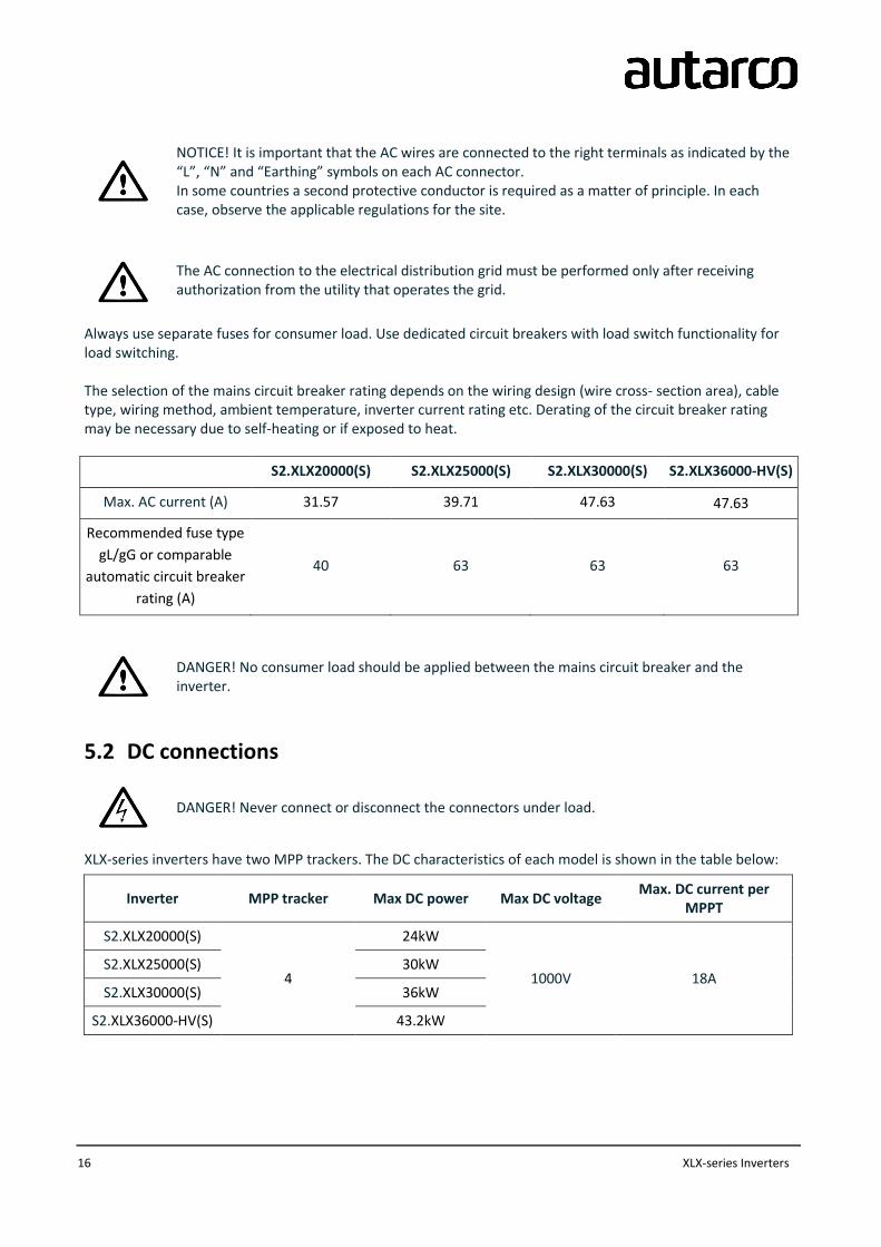
NOTICE! It is important that the AC wires are connected to the right terminals as indicated by the “L”, “N” and “Earthing” symbols on each AC connector. In some countries a second protective conductor is required as a matter of principle. In each case, observe the applicable regulations for the site.
The AC connection to the electrical distribution grid must be performed only after receiving authorization from the utility that operates the grid.
Always use separate fuses for consumer load. Use dedicated circuit breakers with load switch functionality for load switching. The selection of the mains circuit breaker rating depends on the wiring design (wire cross- section area), cable type, wiring method, ambient temperature, inverter current rating etc. Derating of the circuit breaker rating may be necessary due to self-heating or if exposed to heat.
S2.XLX20000(S) S2.XLX25000(S) S2.XLX30000(S) S2.XLX36000-HV(S)
Max. AC current (A) 31.57 39.71 47.63 47.63
Recommended fuse type
gL/gG or comparable
automatic circuit breaker
rating (A)
40 63 63 63
DANGER! No consumer load should be applied between the mains circuit breaker and the inverter.
5.2 DC connections
DANGER! Never connect or disconnect the connectors under load.
XLX-series inverters have two MPP trackers. The DC characteristics of each model is shown in the table below:
Inverter MPP tracker Max DC power Max DC voltage Max. DC current per
MPPT
S2.XLX20000(S)
4
24kW
1000V 18A S2.XLX25000(S) 30kW
S2.XLX30000(S) 36kW
S2.XLX36000-HV(S) 43.2kW
installation and operation manual
IM-S2-XLX-EN-V1.4 17
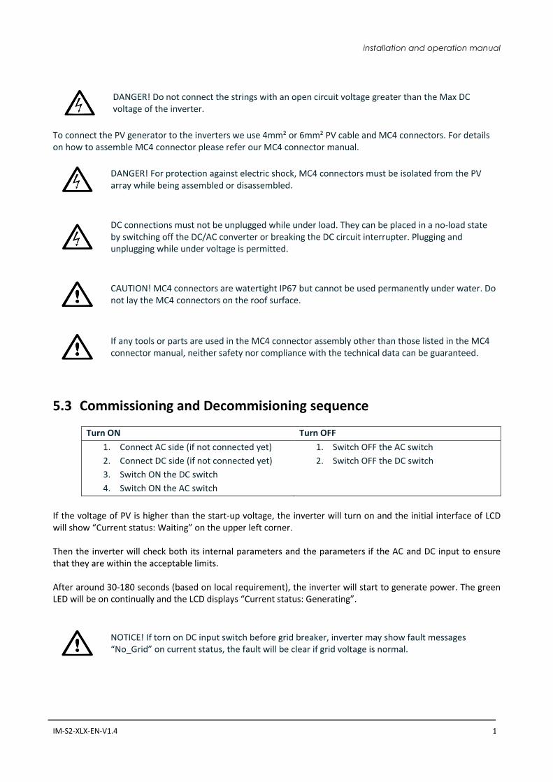
DANGER! Do not connect the strings with an open circuit voltage greater than the Max DC voltage of the inverter.
To connect the PV generator to the inverters we use 4mm² or 6mm² PV cable and MC4 connectors. For details on how to assemble MC4 connector please refer our MC4 connector manual.
DANGER! For protection against electric shock, MC4 connectors must be isolated from the PV array while being assembled or disassembled.
DC connections must not be unplugged while under load. They can be placed in a no-load state by switching off the DC/AC converter or breaking the DC circuit interrupter. Plugging and unplugging while under voltage is permitted.
CAUTION! MC4 connectors are watertight IP67 but cannot be used permanently under water. Do not lay the MC4 connectors on the roof surface.
If any tools or parts are used in the MC4 connector assembly other than those listed in the MC4 connector manual, neither safety nor compliance with the technical data can be guaranteed.
5.3 Commissioning and Decommisioning sequence
Turn ON Turn OFF
1. Connect AC side (if not connected yet)
2. Connect DC side (if not connected yet)
3. Switch ON the DC switch
4. Switch ON the AC switch
1. Switch OFF the AC switch
2. Switch OFF the DC switch
If the voltage of PV is higher than the start-up voltage, the inverter will turn on and the initial interface of LCD will show “Current status: Waiting” on the upper left corner. Then the inverter will check both its internal parameters and the parameters if the AC and DC input to ensure that they are within the acceptable limits. After around 30-180 seconds (based on local requirement), the inverter will start to generate power. The green LED will be on continually and the LCD displays “Current status: Generating”.
NOTICE! If torn on DC input switch before grid breaker, inverter may show fault messages “No_Grid” on current status, the fault will be clear if grid voltage is normal.
18 XLX-series Inverters
6. Operation
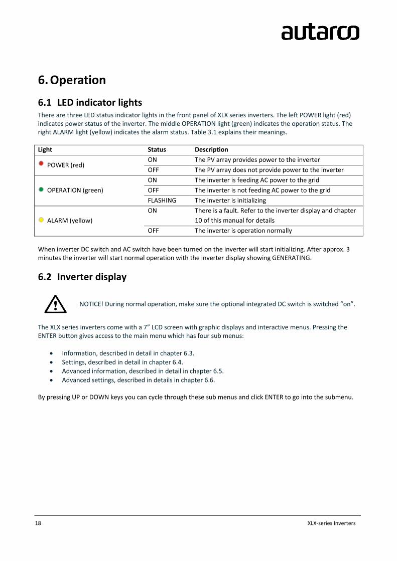
6.1 LED indicator lights There are three LED status indicator lights in the front panel of XLX series inverters. The left POWER light (red) indicates power status of the inverter. The middle OPERATION light (green) indicates the operation status. The right ALARM light (yellow) indicates the alarm status. Table 3.1 explains their meanings.
Light Status Description
POWER (red) ON The PV array provides power to the inverter
OFF The PV array does not provide power to the inverter
OPERATION (green)
ON The inverter is feeding AC power to the grid
OFF The inverter is not feeding AC power to the grid
FLASHING The inverter is initializing
ALARM (yellow)
ON There is a fault. Refer to the inverter display and chapter
10 of this manual for details
OFF The inverter is operation normally
When inverter DC switch and AC switch have been turned on the inverter will start initializing. After approx. 3 minutes the inverter will start normal operation with the inverter display showing GENERATING.
6.2 Inverter display
NOTICE! During normal operation, make sure the optional integrated DC switch is switched “on”.
The XLX series inverters come with a 7” LCD screen with graphic displays and interactive menus. Pressing the ENTER button gives access to the main menu which has four sub menus:
Information, described in detail in chapter 6.3.
Settings, described in detail in chapter 6.4.
Advanced information, described in detail in chapter 6.5.
Advanced settings, described in details in chapter 6.6. By pressing UP or DOWN keys you can cycle through these sub menus and click ENTER to go into the submenu.
installation and operation manual
IM-S2-XLX-EN-V1.4 19
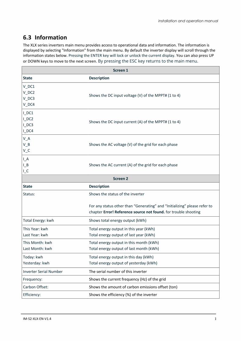
6.3 Information The XLX series inverters main menu provides access to operational data and information. The information is displayed by selecting "Information" from the main menu. By default the inverter display will scroll through the information states below. Pressing the ENTER key will lock or unlock the current display. You can also press UP
or DOWN keys to move to the next screen. By pressing the ESC key returns to the main menu.
Screen 1
State Description
V_DC1
V_DC2
V_DC3
V_DC4
Shows the DC input voltage (V) of the MPPT# (1 to 4)
I_DC1
I_DC2
I_DC3
I_DC4
Shows the DC input current (A) of the MPPT# (1 to 4)
V_A
V_B
V_C
Shows the AC voltage (V) of the grid for each phase
I_A
I_B
I_C
Shows the AC current (A) of the grid for each phase
Screen 2
State Description
Status:
Shows the status of the inverter
For any status other than “Generating” and “Initializing” please refer to
chapter Error! Reference source not found. for trouble shooting
Total Energy: kwh Shows total energy output (kWh)
This Year: kwh
Last Year: kwh
Total energy output in this year (kWh)
Total energy output of last year (kWh)
This Month: kwh
Last Month: kwh
Total energy output in this month (kWh)
Total energy output of last month (kWh)
Today: kwh
Yesterday: kwh
Total energy output in this day (kWh)
Total energy output of yesterday (kWh)
Inverter Serial Number The serial number of this inverter
Frequency: Shows the current frequency (Hz) of the grid
Carbon Offset: Shows the amount of carbon emissions offset (ton)
Efficiency: Shows the efficiency (%) of the inverter
20 XLX-series Inverters
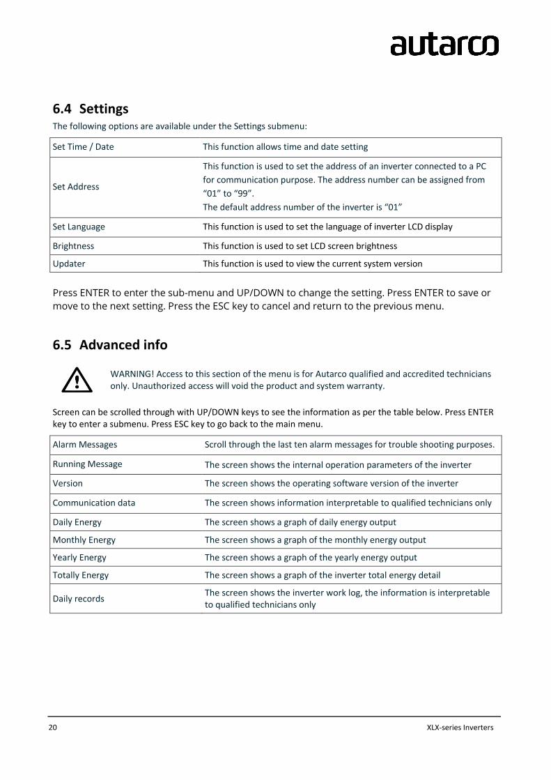
6.4 Settings The following options are available under the Settings submenu:
Set Time / Date This function allows time and date setting
Set Address
This function is used to set the address of an inverter connected to a PC
for communication purpose. The address number can be assigned from
“01” to “99”.
The default address number of the inverter is “01”
Set Language This function is used to set the language of inverter LCD display
Brightness This function is used to set LCD screen brightness
Updater This function is used to view the current system version
Press ENTER to enter the sub-menu and UP/DOWN to change the setting. Press ENTER to save or
move to the next setting. Press the ESC key to cancel and return to the previous menu.
6.5 Advanced info
WARNING! Access to this section of the menu is for Autarco qualified and accredited technicians only. Unauthorized access will void the product and system warranty.
Screen can be scrolled through with UP/DOWN keys to see the information as per the table below. Press ENTER key to enter a submenu. Press ESC key to go back to the main menu.
Alarm Messages Scroll through the last ten alarm messages for trouble shooting purposes.
Running Message The screen shows the internal operation parameters of the inverter
Version The screen shows the operating software version of the inverter
Communication data The screen shows information interpretable to qualified technicians only
Daily Energy The screen shows a graph of daily energy output
Monthly Energy The screen shows a graph of the monthly energy output
Yearly Energy The screen shows a graph of the yearly energy output
Totally Energy The screen shows a graph of the inverter total energy detail
Daily records The screen shows the inverter work log, the information is interpretable to qualified technicians only
installation and operation manual
IM-S2-XLX-EN-V1.4 21
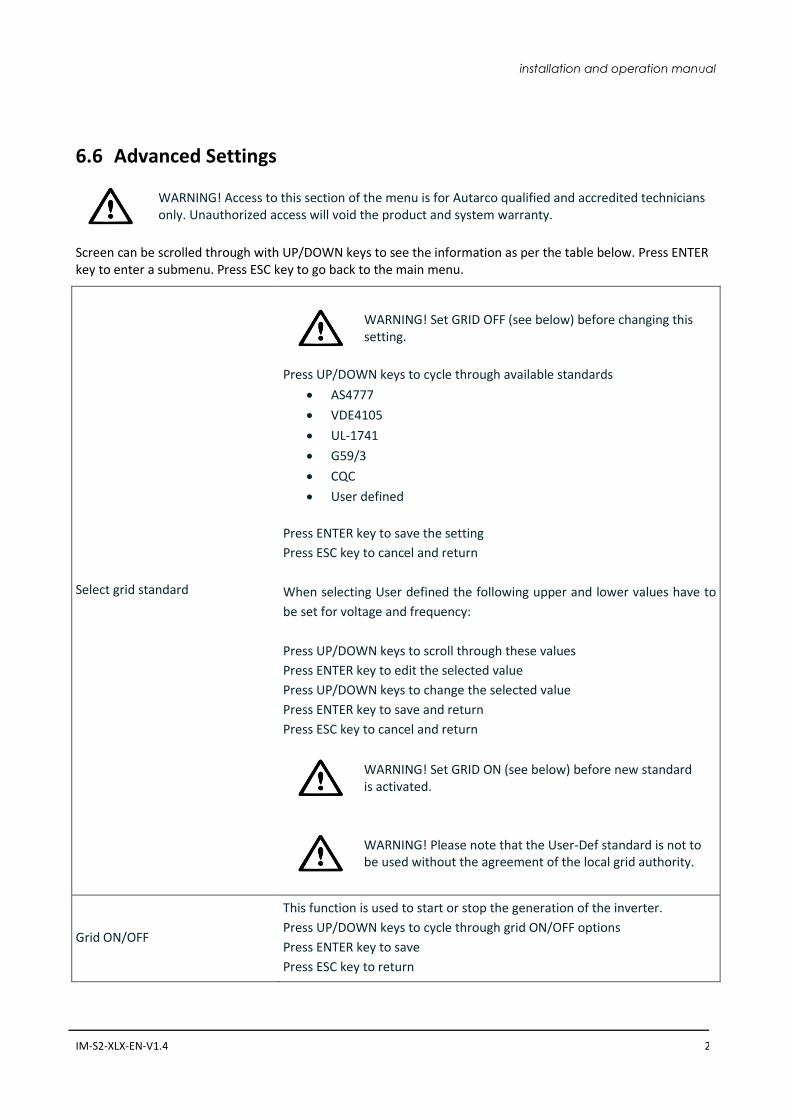
6.6 Advanced Settings
WARNING! Access to this section of the menu is for Autarco qualified and accredited technicians only. Unauthorized access will void the product and system warranty.
Screen can be scrolled through with UP/DOWN keys to see the information as per the table below. Press ENTER key to enter a submenu. Press ESC key to go back to the main menu.
Select grid standard
WARNING! Set GRID OFF (see below) before changing this setting.
Press UP/DOWN keys to cycle through available standards
AS4777
VDE4105
UL-1741
G59/3
CQC
User defined
Press ENTER key to save the setting
Press ESC key to cancel and return
When selecting User defined the following upper and lower values have to
be set for voltage and frequency:
Press UP/DOWN keys to scroll through these values
Press ENTER key to edit the selected value
Press UP/DOWN keys to change the selected value
Press ENTER key to save and return
Press ESC key to cancel and return
WARNING! Set GRID ON (see below) before new standard is activated.
WARNING! Please note that the User-Def standard is not to be used without the agreement of the local grid authority.
Grid ON/OFF
This function is used to start or stop the generation of the inverter.
Press UP/DOWN keys to cycle through grid ON/OFF options
Press ENTER key to save
Press ESC key to return
22 XLX-series Inverters
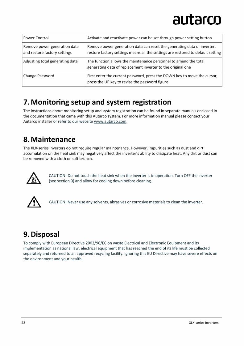
Power Control Activate and reactivate power can be set through power setting button
Remove power generation data
and restore factory settings
Remove power generation data can reset the generating data of inverter,
restore factory settings means all the settings are restored to default setting
Adjusting total generating data The function allows the maintenance personnel to amend the total
generating data of replacement inverter to the original one
Change Password First enter the current password, press the DOWN key to move the cursor,
press the UP key to revise the password figure.
7. Monitoring setup and system registration The instructions about monitoring setup and system registration can be found in separate manuals enclosed in the documentation that came with this Autarco system. For more information manual please contact your Autarco installer or refer to our website www.autarco.com.
8. Maintenance The XLX-series inverters do not require regular maintenance. However, impurities such as dust and dirt accumulation on the heat sink may negatively affect the inverter’s ability to dissipate heat. Any dirt or dust can be removed with a cloth or soft brunch.
CAUTION! Do not touch the heat sink when the inverter is in operation. Turn OFF the inverter (see section 0) and allow for cooling down before cleaning.
CAUTION! Never use any solvents, abrasives or corrosive materials to clean the inverter.
9. Disposal To comply with European Directive 2002/96/EC on waste Electrical and Electronic Equipment and its implementation as national law, electrical equipment that has reached the end of its life must be collected separately and returned to an approved recycling facility. Ignoring this EU Directive may have severe effects on the environment and your health.
installation and operation manual
IM-S2-XLX-EN-V1.4 23
10. Troubleshooting
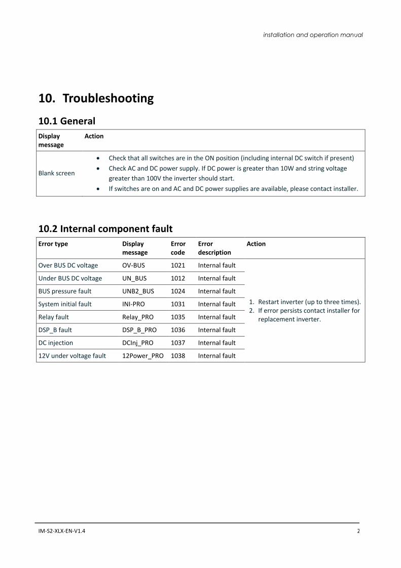
10.1 General
Display message
Action
Blank screen
Check that all switches are in the ON position (including internal DC switch if present)
Check AC and DC power supply. If DC power is greater than 10W and string voltage
greater than 100V the inverter should start.
If switches are on and AC and DC power supplies are available, please contact installer.
10.2 Internal component fault
Error type Display message
Error code
Error description
Action
Over BUS DC voltage OV-BUS 1021 Internal fault
1. Restart inverter (up to three times). 2. If error persists contact installer for
replacement inverter.
Under BUS DC voltage UN_BUS 1012 Internal fault
BUS pressure fault UNB2_BUS 1024 Internal fault
System initial fault INI-PRO 1031 Internal fault
Relay fault Relay_PRO 1035 Internal fault
DSP_B fault DSP_B_PRO 1036 Internal fault
DC injection DCInj_PRO 1037 Internal fault
12V under voltage fault 12Power_PRO 1038 Internal fault
24 XLX-series Inverters
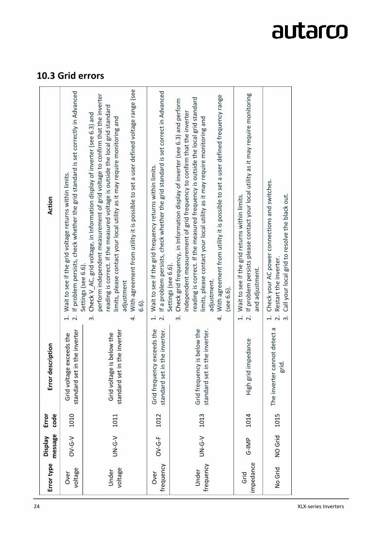
Erro
r ty
pe
Dis
pla
y m
essa
ge
Erro
r co
de
Erro
r d
escr
ipti
on
A
ctio
n
Ove
r vo
ltag
e O
V-G
-V
101
0
Gri
d v
olt
age
exce
ed
s th
e st
and
ard
set
in t
he
inve
rter
1.
Wai
t to
see
if t
he
grid
vo
ltag
e re
turn
s w
ith
in li
mit
s.
2.
If p
rob
lem
per
sist
s, c
hec
k w
het
her
th
e gr
id s
tan
dar
d is
set
co
rrec
tly
in A
dva
nce
d
Sett
ings
(se
e 6
.6).
3
.C
hec
k V
_AC
, gri
d v
olt
age,
in In
form
atio
n d
isp
lay
of
inve
rter
(se
e 6
.3)
and
p
erfo
rm in
dep
end
ent
mea
sure
men
t o
f gr
id v
olt
age
to c
on
firm
th
at t
he
inve
rter
re
adin
g is
co
rrec
t. If
th
e m
easu
red
vo
ltag
e is
ou
tsid
e th
e lo
cal g
rid
sta
nd
ard
lim
its,
ple
ase
con
tact
yo
ur
loca
l uti
lity
as it
may
req
uir
e m
on
ito
rin
g an
d
adju
stm
ent
4.
Wit
h a
gree
men
t fr
om
uti
lity
it is
po
ssib
le t
o s
et a
use
r d
efin
ed v
olt
age
ran
ge (
see
6.6
).
Un
der
vo
ltag
e U
N-G
-V
101
1
Gri
d v
olt
age
is b
elo
w t
he
stan
dar
d s
et in
th
e in
vert
er
Ove
r fr
equ
ency
O
V-G
-F
101
2
Gri
d f
req
uen
cy e
xcee
ds
the
stan
dar
d s
et in
th
e in
vert
er.
1.
Wai
t to
see
if t
he
grid
fre
qu
ency
ret
urn
s w
ith
in li
mit
s.
2.
If a
pro
ble
m p
ersi
sts,
ch
eck
wh
eth
er t
he
grid
sta
nd
ard
is s
et c
orr
ect
in A
dva
nce
d
Sett
ings
(se
e 6
.6).
3
.C
hec
k gr
id f
req
uen
cy, i
n In
form
atio
n d
isp
lay
of
inve
rter
(se
e 6
.3)
and
per
form
in
dep
end
ent
mea
sure
men
t o
f gr
id f
req
uen
cy t
o c
on
firm
th
at t
he
inve
rter
re
adin
g is
co
rrec
t. If
th
e m
easu
red
fre
qu
ency
is o
uts
ide
the
loca
l gri
d s
tan
dar
d
limit
s, p
leas
e co
nta
ct y
ou
r lo
cal u
tilit
y as
it m
ay r
equ
ire
mo
nit
ori
ng
and
ad
just
men
t.
4.
Wit
h a
gree
men
t fr
om
uti
lity
it is
po
ssib
le t
o s
et a
use
r d
efin
ed f
req
uen
cy r
ange
(s
ee 6
.6).
Un
der
fr
equ
ency
U
N-G
-V
101
3
Gri
d f
req
uen
cy is
bel
ow
th
e st
and
ard
set
in t
he
inve
rter
.
Gri
d
imp
edan
ce
G-I
MP
101
4
Hig
h g
rid
imp
edan
ce
1.
Wai
t to
see
if t
he
grid
ret
urn
s w
ith
in li
mit
s.
2.
If p
rob
lem
per
sist
s p
leas
e co
nta
ct y
ou
r lo
cal u
tilit
y as
it m
ay r
equ
ire
mo
nit
ori
ng
and
ad
just
men
t.
No
Gri
d
NO
Gri
d
101
5
The
inve
rter
can
no
t d
etec
t a
grid
.
1.
Ch
eck
you
r A
C p
ow
er c
on
nec
tio
ns
and
sw
itch
es.
2.
Re
star
t th
e in
vert
er.
3.
Cal
l yo
ur
loca
l gri
d t
o r
eso
lve
the
bla
ck o
ut.
10.3 Grid errors
installation and operation manual
IM-S2-XLX-EN-V1.4 25
Erro
r ty
pe
Dis
pla
y m
essa
ge
Erro
r co
de
Erro
r d
escr
ipti
on
A
ctio
n
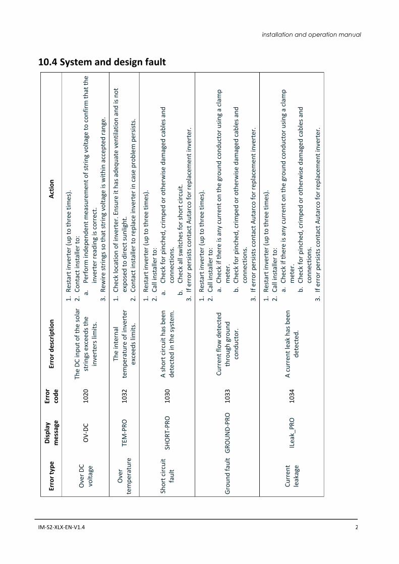
Ove
r D
C
volt
age
O
V-D
C
102
0
The
DC
inp
ut
of
the
sola
r st
rin
gs e
xcee
ds
the
inve
rter
s lim
its.
1.
Re
star
t in
vert
er (
up
to
th
ree
tim
es).
2
.C
on
tact
inst
alle
r to
: a.
Per
form
ind
epen
den
t m
easu
rem
ent
of
stri
ng
volt
age
to c
on
firm
th
at t
he
inve
rter
rea
din
g is
co
rrec
t.
3.
Re
wir
e st
rin
gs s
o t
hat
str
ing
volt
age
is w
ith
in a
ccep
ted
ran
ge.
Ove
r te
mp
erat
ure
TE
M-P
RO
1
032
Th
e in
tern
al
tem
per
atu
re o
f in
vert
er
exce
eds
limit
s.
1.
Ch
eck
loca
tio
n o
f in
vert
er. E
nsu
re it
has
ad
equ
ate
ven
tila
tio
n a
nd
is n
ot
exp
ose
d t
o d
irec
t su
nlig
ht.
2
.C
on
tact
inst
alle
r to
rep
lace
inve
rter
in c
ase
pro
ble
m p
ersi
sts.
Sho
rt c
ircu
it
fau
lt
SHO
RT-
PRO
1
030
A
sh
ort
cir
cuit
has
bee
n
det
ecte
d in
th
e sy
stem
.
1.
Re
star
t in
vert
er (
up
to
th
ree
tim
es).
2
.C
all i
nst
alle
r to
: a.
Ch
eck
for
pin
ched
, cri
mp
ed o
r o
ther
wis
e d
amag
ed c
able
s an
d
con
nec
tio
ns.
b
.C
hec
k al
l sw
itch
es f
or
sho
rt c
ircu
it.
3.
If e
rro
r p
ersi
sts
con
tact
Au
tarc
o f
or
rep
lace
men
t in
vert
er.
Gro
un
d f
ault
G
RO
UN
D-P
RO
1
033
C
urr
ent
flo
w d
etec
ted
th
rou
gh g
rou
nd
co
nd
uct
or.
1.
Re
star
t in
vert
er (
up
to
th
ree
tim
es).
2
.C
all i
nst
alle
r to
: a.
Ch
eck
if t
her
e is
an
y cu
rren
t o
n t
he
gro
un
d c
on
du
cto
r u
sin
g a
clam
p
met
er.
b.
Ch
eck
for
pin
ched
, cri
mp
ed o
r o
ther
wis
e d
amag
ed c
able
s an
d
con
nec
tio
ns.
3
.If
err
or
per
sist
s co
nta
ct A
uta
rco
fo
r re
pla
cem
ent
inve
rter
.
Cu
rren
t le
akag
e IL
eak_
PRO
1
034
A
cu
rren
t le
ak h
as b
een
d
etec
ted
.
1.
Re
star
t in
vert
er (
up
to
th
ree
tim
es).
2
.C
all i
nst
alle
r to
: a.
Ch
eck
if t
her
e is
an
y cu
rren
t o
n t
he
gro
un
d c
on
du
cto
r u
sin
g a
clam
p
met
er.
b.
Ch
eck
for
pin
ched
, cri
mp
ed o
r o
ther
wis
e d
amag
ed c
able
s an
d
con
nec
tio
ns.
3
.If
err
or
per
sist
s co
nta
ct A
uta
rco
fo
r re
pla
cem
ent
inve
rter
.
10.4 System and design fault
26 XLX-series Inverters
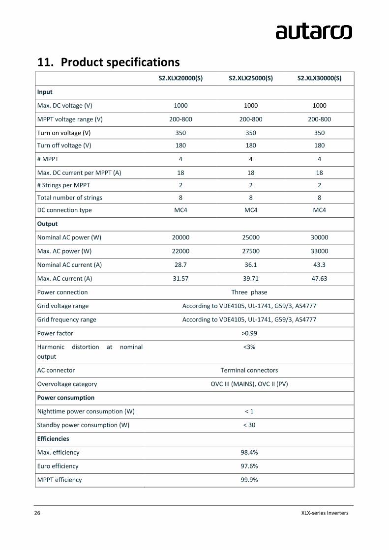
11. Product specifications S2.XLX20000(S) S2.XLX25000(S) S2.XLX30000(S)
Input
Max. DC voltage (V) 1000 1000 1000
MPPT voltage range (V) 200-800 200-800 200-800
Turn on voltage (V) 350 350 350
Turn off voltage (V) 180 180 180
# MPPT 4 4 4
Max. DC current per MPPT (A) 18 18 18
# Strings per MPPT 2 2 2
Total number of strings 8 8 8
DC connection type MC4 MC4 MC4
Output
Nominal AC power (W) 20000 25000 30000
Max. AC power (W) 22000 27500 33000
Nominal AC current (A) 28.7 36.1 43.3
Max. AC current (A) 31.57 39.71 47.63
Power connection Three phase
Grid voltage range According to VDE4105, UL-1741, G59/3, AS4777
Grid frequency range According to VDE4105, UL-1741, G59/3, AS4777
Power factor >0.99
Harmonic distortion at nominal
output
<3%
AC connector Terminal connectors
Overvoltage category OVC III (MAINS), OVC II (PV)
Power consumption
Nighttime power consumption (W) < 1
Standby power consumption (W) < 30
Efficiencies
Max. efficiency 98.4%
Euro efficiency 97.6%
MPPT efficiency 99.9%
installation and operation manual
IM-S2-XLX-EN-V1.4 27
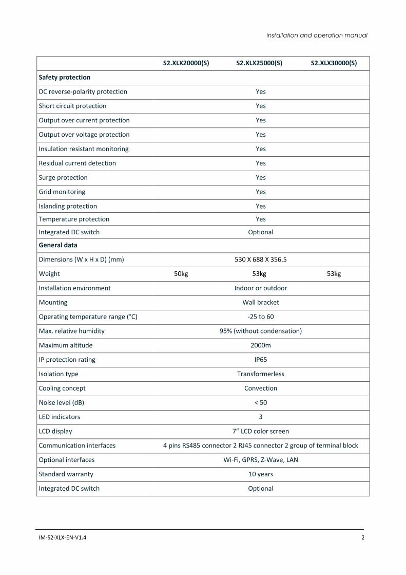
S2.XLX20000(S) S2.XLX25000(S) S2.XLX30000(S)
Safety protection
DC reverse-polarity protection Yes
Short circuit protection Yes
Output over current protection Yes
Output over voltage protection Yes
Insulation resistant monitoring Yes
Residual current detection Yes
Surge protection Yes
Grid monitoring Yes
Islanding protection Yes
Temperature protection Yes
Integrated DC switch Optional
General data
Dimensions (W x H x D) (mm) 530 X 688 X 356.5
Weight 50kg 53kg 53kg
Installation environment Indoor or outdoor
Mounting Wall bracket
Operating temperature range (°C) -25 to 60
Max. relative humidity 95% (without condensation)
Maximum altitude 2000m
IP protection rating IP65
Isolation type Transformerless
Cooling concept Convection
Noise level (dB) < 50
LED indicators 3
LCD display 7” LCD color screen
Communication interfaces 4 pins RS485 connector 2 RJ45 connector 2 group of terminal block
Optional interfaces Wi-Fi, GPRS, Z-Wave, LAN
Standard warranty 10 years
Integrated DC switch Optional