Embed Size (px)
Citation preview
PTG-10 Operations Manual
1-1
Installation and Operation Manual
PTG-10 Pilot Tone Generator
Designed and Manufactured by:
Raytheon
5800 Departure Drive
Raleigh, NC 27616
P/N 5970-900200 Revision 3.1 January 2009
PTG-10 Operations Manual
1-2
Warranty JPS Communications warrants its manufactured equipment to be free from defects in materials and workmanship, and to conform to published specifications for a period of 18 months from the date of shipment from the factory or 12 months from installation, whichever occurs first.
JPS warrants its service work performed in connection with this warranty to be free from defects in materials and workmanship for a period of 90 days from the date the work is performed.
If a defect occurs within the warranty period, the buyer shall notify JPS immediately. JPS will repair or replace the equipment at its option, upon return of the equipment, shipping prepaid, to the JPS facility in Raleigh, North Carolina, USA
This warranty does not apply to damage caused by accidents, abuse or improper installation.
NO OTHER WARRANTY, EXPRESSED OR IMPLIED, INCLUDING BUT NOT LIMITED TO THE IMPLIED WARRANTIES OF MERCHANTABILITY AND FITNESS FOR A PARTICULAR PURPOSE, SHALL APPLY.
NOTICE
Raytheon reserves the right to make changes to the equipment and specifications without prior notice.
PROPRIETARY STATEMENT
The information contained in this manual is the property of Raytheon and is intended for the purchaser’s use only. It may not be reproduced without the express written consent of Raytheon.
Raytheon
5800 Departure Drive
Raleigh, NC 27616
Phone: (919) 790-1011
Fax: (919) 790-1456
PTG-10 Operations Manual
1-3
Table of Contents
1 GENERAL INFORMATION............................................................................................................................ 1-1 1.1 SCOPE ................................................................................................................................................... 1-1 1.2 DESCRIPTION ........................................................................................................................................ 1-1
1.2.1 General............................................................................................................................................ 1-1 1.2.2 Circuitry and Block Diagrams ........................................................................................................ 1-2 1.2.3 Mechanical Assembly...................................................................................................................... 1-2 1.2.4 Function and Operation .................................................................................................................. 1-2 1.2.5 Power Supply .................................................................................................................................. 1-2 1.2.6 Limitations ...................................................................................................................................... 1-3
2 INSTALLATION.............................................................................................................................................. 2-1 2.1 GENERAL.............................................................................................................................................. 2-1 2.2 UNPACKING AND INSPECTION............................................................................................................... 2-1 2.3 RESHIPMENT OF EQUIPMENT ................................................................................................................ 2-1 2.4 INSTALLATION OVERVIEW.................................................................................................................... 2-2 2.5 INSTALLATION CONSIDERATIONS ......................................................................................................... 2-2 2.6 POWER REQUIREMENTS ........................................................................................................................ 2-2 2.7 CONFIGURING THE PTG-10 .................................................................................................................. 2-2
2.7.1 Jumper Settings ............................................................................................................................... 2-2 2.7.2 Potentiometer Adjustments.............................................................................................................. 2-3
2.8 INTERCONNECT INFORMATION ............................................................................................................. 2-3 2.8.1 Input and Output Connections Plus Power and Ground................................................................. 2-3
2.9 SETTING LEVELS................................................................................................................................... 2-3 3 OPERATION................................................................................................................................................... 3-1
3.1 GENERAL.............................................................................................................................................. 3-1 3.2 OPERATIONAL INDICATORS .................................................................................................................. 3-1
3.2.1 Power Indicator .............................................................................................................................. 3-1 3.2.2 Tone Indicator................................................................................................................................. 3-1
3.3 OPERATION........................................................................................................................................... 3-1 4 THEORY OF OPERATION............................................................................................................................. 4-1
4.1 GENERAL.............................................................................................................................................. 4-1 4.2 TONE CIRCUIT ...................................................................................................................................... 4-1 4.3 POWER SUPPLY..................................................................................................................................... 4-1
5 MAINTENANCE AND REPAIR...................................................................................................................... 5-1 5.1 GENERAL.............................................................................................................................................. 5-1 5.2 PREVENTIVE MAINTENANCE................................................................................................................. 5-1 5.3 REPAIR OR REPLACEMENT.................................................................................................................... 5-1
5.3.1 General Precautions and Notes ...................................................................................................... 5-1 6 INDEX............................................................................................................................................................. 6-1
PTG-10 Operations Manual
1-4
List of Figures
FIGURE 2-1 – OUTLINE DIMENSIONS........................................................................................................................2-5 FIGURE 2-2 – LOCATIONS OF INDICATORS AND ADJUSTMENTS................................................................................2-6 FIGURE 5-1 – CIRCUIT DIAGRAM 1...........................................................................................................................5-2 FIGURE 5-2 – CIRCUIT DIAGRAM 2...........................................................................................................................5-3 FIGURE 5-3 – WIRING DIAGRAM 1 ...........................................................................................................................5-4 FIGURE 5-4 – BLOCK DIAGRAM 1 ............................................................................................................................5-5
List of Tables
TABLE 1-1 SPECIFICATIONS .........................................................................................................................1-3 TABLE 1-2 EQUIPMENT AND ACCESSORIES SUPPLIED..........................................................................1-3 TABLE 2-1 JP1-INPUT/OUTPUT CONNECTOR .....................................................................................................2-4
PTG-10 Operations Manual
1-1
1 General Information
1.1 Scope
This instruction manual provides the information necessary to install, operate, repair and maintain the PTG-10 Pilot Tone Generator.
1.2 Description
1.2.1 General In an LMR voting system, receivers are strategically placed throughout a geographic area (at voting sites) to fill in dead spots where portable radios cannot normally be heard by other portables, by the repeater, or by the dispatcher. The audio from each receiver is linked to the voter, which continuously compares the signals from all receivers and passes through the best quality signal to the dispatcher or to the local repeater. In this way, any portable in the voting area can be heard by the dispatcher, or by any other portable through the local repeater. In this system, it is necessary to transfer a receiver’s COR or COS (Carrier Operated Relay or Carrier Operated Squelch) signal to the voter from a remote receiver site. COR is an indication that the receiver has broken squelch; the voter needs this information to know which receiver site or sites are currently unsquelched and therefore receiving a valid input signal.
The PTG-10 Pilot Tone Generator Module produces a controlled pilot tone that transfers the COR signal from a remote receiver site to a voter. The PTG-10 transfers the COR signal over the same path as the receive audio, eliminating the cost of a second communications path for the COR signal. Audio output (an AC signal) exits a receiver through one pair of wires and the COR (a DC logic signal) exits the receiver on another wire making it impossible to carry both the audio and the COR on the same audio pair. The PTG-10 converts the COR signal to a tone which is mixed with the audio from the receiver, removing the need for a COR line. The PTG-10 works by injecting a pilot tone on the audio line whenever the associated receiver is squelched, and removes the tone whenever the receiver is unsquelched. When the receiver used in the voting application detects carrier (receives a signal), it unsquelches and issues a COR signal to the PTG-10. When the PTG-10 receives a COR signal the tone is removed from the audio link and the receiver audio is passed through the link to the voter.
The pilot tone from the PTG-10 can also function as a line proving tone to insure the integrity of the audio link in the following way: the removal of the pilot tone on the link notifies the voter to begin looking for voice signals from the voting receiver. If the voter doesn’t sense voice coming from the receiver within a programmed time, it faults that particular voting site on the assumption that either the voting receiver is not functioning, or the link is broken between the receiver and the voter. The SNV-12 disallows use of that voting input until voice is received from the distant receiver or until the pilot tone returns.
The PTG-10 is capable of injecting either of two user selectable pilot tones: 1950 Hz or 2175 Hz. The module is 6.84" x 2.42" x 1.2" and is enclosed in a metal box suitable for mounting to
PTG-10 Operations Manual
1-2
any flat surface or to a standard 19" rack. The mounting tabs are designed such that bolting three units together side by side will span the standard 19" size rack. System interconnections are made by wiring to a screwdriver type terminal block. Audio input from the receiver is unbalanced, while audio output to the voter is configured for 600 Ohm balanced operation. The terminal block has provisions for a COR input (either positive logic “COR” or negative logic “/COR”), power input (+11 to +15 VDC) and ground. Two LEDs are provided: One indicates the when a pilot tone is being mixed; the other is a power indicator. The pilot tone level and the audio output level (voice plus pilot tone) are independently adjustable.
1.2.2 Circuitry and Block Diagrams Refer to Figure 5-1. JP1 is the terminal block that interfaces all inputs and outputs between the PTG-10 and the outside world. Audio enters the unit from a receiver at terminal 4 with respect to ground, terminals 1 and 7. This audio is mixed at the mixer amp with the tone produced by the tone oscillator. Tone frequency selection is made using switch SW1. Placing the switch in position (0) will yield a 2175 Hz tone. Position (1) will yield a 1950 Hz tone. The pilot tone and receive audio tones are sent the final amp stage which controls the output level. The output is sent to a matching transformer for balanced 600 Ohms. When the unit receives a COR signal on terminal 2 or a /COR signal on terminal 3 the tone is removed from the audio chain. When the unit receives a COR signal (positive or negative) the yellow COR led will illuminate. The balanced output is sent to pins 5 and 6 of JP1.
1.2.3 Mechanical Assembly Please refer to Figure 2-1. This drawing shows the front of the unit with rack mount tabs on each side plus the drawing shows the side, top and bottom views. The rack mount tabs enable the unit to be bolted to one side (either side of unit) of a standard 19" rack, possibly on the rear of the rack behind other equipment. Another option is bolting three of the units together side by side: this will span the standard 19" rack enabling mounting to the rack at both ends. The unit consists of a ‘C’ shaped top cover that is attached by two screws to the main chassis. The circuit board is secured to the chassis via four standoffs.
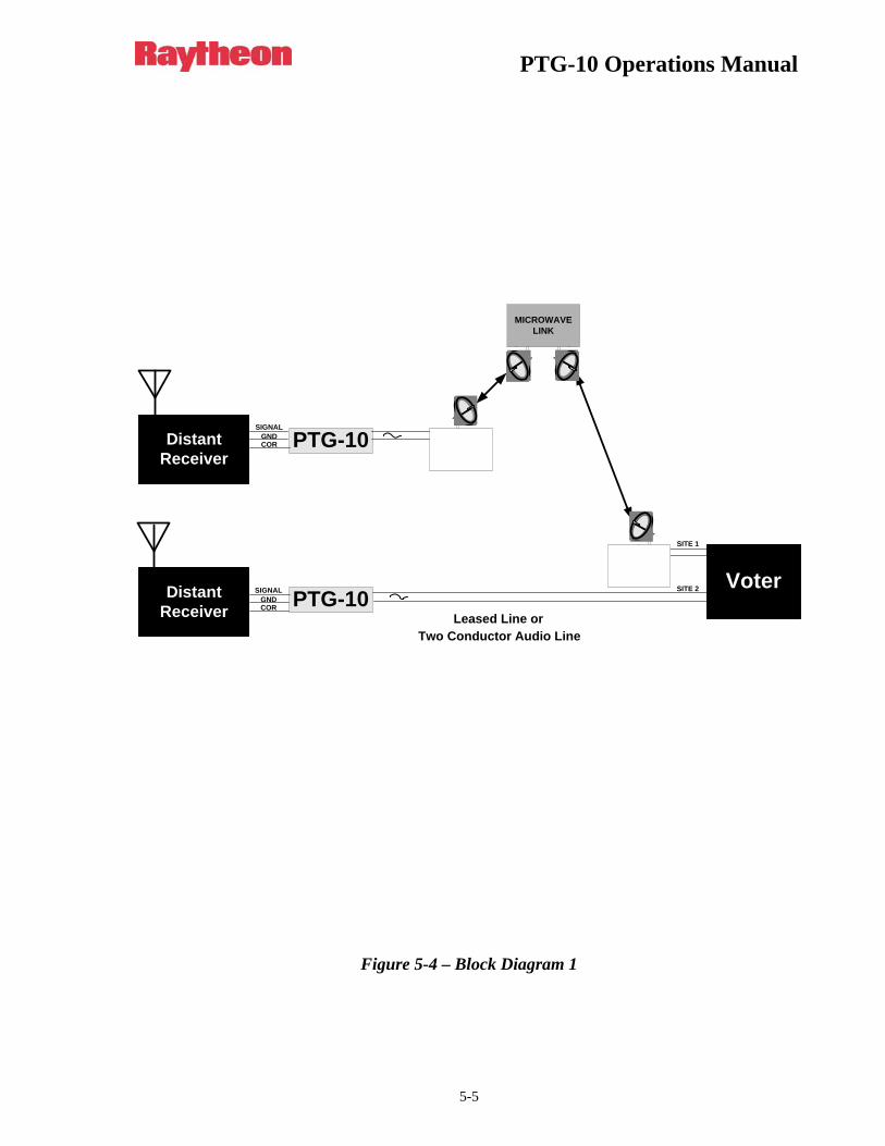
1.2.4 Function and Operation Please refer to Figure 5-4. The PTG-10 enables two conductors to carry both an audio signal and a COR signal. The PTG-10 can also function as a line proving tone to insure the integrity of the audio link. The tone produced by the PTG-10 will be notched out in the voter. Two LEDs allow status monitoring. A green LED indicates if the system is getting power, and an amber LED indicates when the system is mixing a pilot tone with the throughput RX audio. The unit will accept either positive or negative logic. Whenever the PTG-10 COR inputs gate the pilot tone. When COR is inactive, the PTG-10 outputs pilot tone. This audio plus pilot tone signal can be sent to a voter via a microwave link, leased lines or twisted pair.
1.2.5 Power Supply Power is fed into the unit via pin 8 of JP1 and ground on pins 1 and 7; this is shown on Figure 5-1 and Figure 5-3. The unit produces three different voltage supplies, +12 VDC, +5 VDC, and - 10 VDC. Under normal conditions the system should draw approximately 40 mA. The input is reverse polarity protected. If the power polarity is accidentally reversed, the unit will not operate, but it will not be damaged.
PTG-10 Operations Manual
1-3
1.2.6 Limitations The PTG-10 audio input is single-ended rather than balanced (to match the RX output signal of many receivers). The PTG-10 should be placed near the receiver so that the common mode rejection that a balanced link provides is not needed on the input signal. In contrast, the unit’s audio output is balanced, as the output is likely to be sent over a long distance.
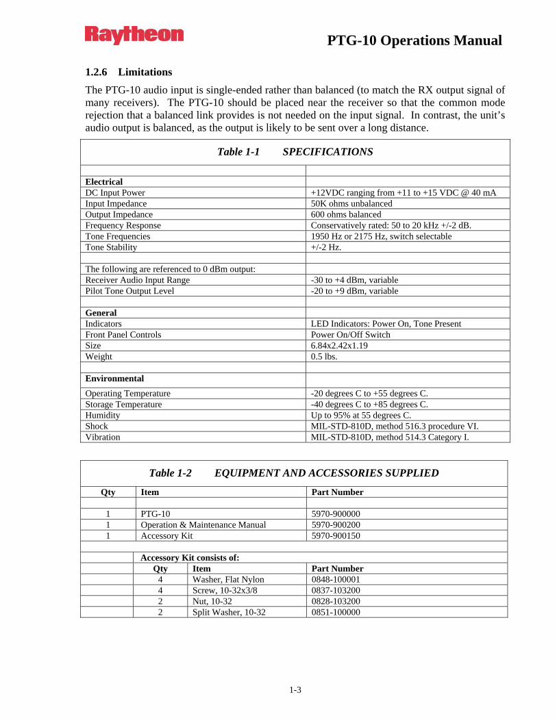
Table 1-1 SPECIFICATIONS
Electrical DC Input Power +12VDC ranging from +11 to +15 VDC @ 40 mA Input Impedance 50K ohms unbalanced Output Impedance 600 ohms balanced Frequency Response Conservatively rated: 50 to 20 kHz +/-2 dB. Tone Frequencies 1950 Hz or 2175 Hz, switch selectable Tone Stability +/-2 Hz. The following are referenced to 0 dBm output: Receiver Audio Input Range -30 to +4 dBm, variable Pilot Tone Output Level -20 to +9 dBm, variable General Indicators LED Indicators: Power On, Tone Present Front Panel Controls Power On/Off Switch Size 6.84x2.42x1.19 Weight 0.5 lbs. Environmental
Operating Temperature -20 degrees C to +55 degrees C. Storage Temperature -40 degrees C to +85 degrees C. Humidity Up to 95% at 55 degrees C. Shock MIL-STD-810D, method 516.3 procedure VI. Vibration MIL-STD-810D, method 514.3 Category I.
Table 1-2 EQUIPMENT AND ACCESSORIES SUPPLIED
Qty Item Part Number
1 PTG-10 5970-900000 1 Operation & Maintenance Manual 5970-900200 1 Accessory Kit 5970-900150
Accessory Kit consists of: Qty Item Part Number 4 Washer, Flat Nylon 0848-100001 4 Screw, 10-32x3/8 0837-103200 2 Nut, 10-32 0828-103200 2 Split Washer, 10-32 0851-100000

PTG-10 Operations Manual
1-4
Blank Page
PTG-10 Operations Manual
2-1
2 Installation
2.1 General
This section provides the instructions for unpacking, inspection, installation and set-up. Also included are directions for reshipment of damaged parts or equipment.
2.2 Unpacking and Inspection
After unpacking the unit, retain the carton and packing materials until the contents have been inspected and checked against the packing list. If there is a shortage or any evidence of damage, do not attempt to use the equipment. Contact the carrier and file a shipment damage claim. A full report of the damage should also be reported to the Customer Service Department. The following information should be included in the report:
1. Order Number
2. Equipment Model and Serial Numbers
3. Shipping Agency
4. Date(s) of Shipment
The Customer Service Department can be reached by phone at (919) 790-1011, by fax at (919) 790-1456. Upon receipt of this information, we will arrange for repair or replacement of the equipment.
2.3 Reshipment of Equipment
If it is necessary to return the equipment to the manufacturer, a Returned Material Authorization (RMA) number must first be obtained from us. This number must be noted on the outside of the packing carton and on all accompanying documents. When packing the unit for reshipment, it is best to use the original packaging for the unit; if this is not possible, make sure that adequate packing material is used to prevent excessive shocks during transport and handling.
Shipment should be made prepaid consigned to:
Raytheon
Customer Service Department
5800 Departure Drive
Raleigh, North Carolina 27616
USA
PTG-10 Operations Manual
2-2
Plainly, mark with indelible ink all mailing documents as follows:
GOODS RETURNED FOR REPAIR
Mark all sides of the package:
FRAGILE - ELECTRONIC EQUIPMENT
Inspect the package prior to shipment to be sure it is properly marked and securely wrapped.
2.4 Installation Overview
Three quick and simple steps are needed to properly install the PTG-10. These steps are:
1. Provide mechanical mounting for the unit
2. Provide the proper DC power for the unit.
3. Interconnect the unit with the communications system via the unit’s JP1 connector.
The PTG-10 is then ready to begin normal operation.
2.5 Installation Considerations
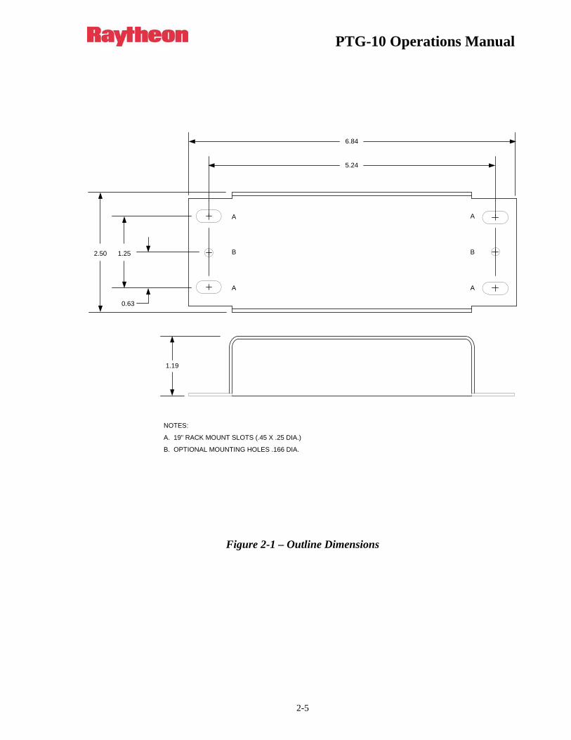
Careful attention to the following installation suggestions should result in the best unit/system performance. Figure 2-1 provides overall unit dimensions.
The PTG-10 must be installed in a structure that provides both protection from the weather and assurance of ambient temperatures between -10 and +55 degrees C. Since the unit is neither splash proof nor corrosion resistant, it must be protected from exposure to salt spray.
NOTE: The PTG-10 is designed to be mounted in a standard EIA 19" wide rack by means of attaching the unit to the rack on either side or bolting three units together to span the entire rack. Screws are provided in the accessory kit for securing the unit to the rack via the front panel.
2.6 Power Requirements
The PTG-10 is designed to operate from +11 to +15 VDC. Power consumption is 0.5 VA typical.
2.7 Configuring the PTG-10
This section explains how to set and adjust all internal jumpers and potentiometers.
2.7.1 Jumper Settings There are two tone frequencies available depending on the setting of SW1. Placing the switch in position (0) will produce a 2175 Hz tone; position (1) will produce a 1950 Hz tone.
PTG-10 Operations Manual
2-3
2.7.2 Potentiometer Adjustments The PTG-10 has two factory set potentiometers. See Figure 2-1. “Overall Adjust” (R8) is set so that a -10 dBm input will produce a 0 dBm output. “Pilot Adjust” (R4) is also set for 0 dBm output. These settings are made with a 600 ohm load across output pins JP1-4 and JP1-5. Both potentiometers can be re-adjusted to fit specific applications. The SNV-12 voter will work best with the pilot tone at the same level as the overall audio. The SNV-12 will completely notch out the pilot tone so that the tone will never be heard at the console or re-transmitted. Also, the high relative pilot tone level ensures that the voter will easily detect it even when there is a large amount of high-frequency roll-off in the line from the receiver to the voter.
When adjusting the overall receiver audio level, make sure that one of the COR inputs is activated. If not, the pilot tone will be mixed with the receiver audio during the adjustment. The simplest method is to ground pin 3 of JP1 (/COR) to remove the pilot tone. Note that the overall level adjust (R8), controls the levels of both the receiver audio and pilot tone. As set at the factory, the pilot tone is at the same level as the receiver audio level. If only R8 is readjusted, the pilot tone will maintain the same relative level. If audio levels different from the factory settings are required, always set the overall level first with R8, then adjust the relative pilot tone level with R4.
2.8 Interconnect Information
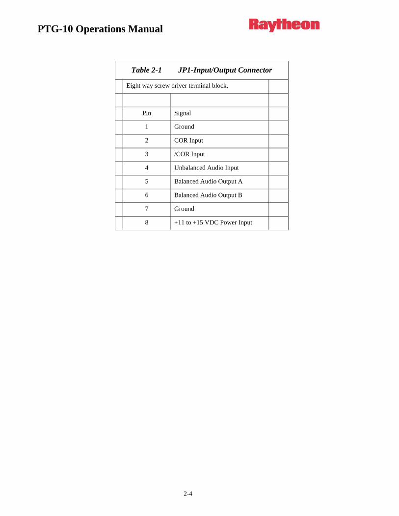
2.8.1 Input and Output Connections Plus Power and Ground All external connections are made via wires that enter the unit through a grommet located on the side of the chassis. The wires are connected to JP1 as shown in Table 2-1.
2.9 Setting Levels
The unit is factory set for the audio input level from the receiver to be -10 dBm and the audio output level of the PTG-10 to be 0 dBm. The PTG-10 is also factory set for the pilot tone level to be 0 dBm. Below is the procedure for setting the levels of the receive and pilot tone audio on the PTG-10:
Please refer to Figure 5-2.
1. Connect the receiver audio to the PTG-10 as shown. Either COR or /COR may be used. The COR input produces a tone when a high signal is present. /COR produces a tone when a low input signal is present.
2. Place a 1 kHz reference test tone (3 kHz deviation wideband / 1.5 kHz narrowband) into the receiver antenna input.
3. Adjust R8 for the desired audio output level measured across pins 5 and 6.
4. Remove the test tone from the receiver so that the receiver squelches; then adjust R4 for the desired tone level.
PTG-10 Operations Manual
2-4
Table 2-1 JP1-Input/Output Connector
Eight way screw driver terminal block.
Pin Signal
1 Ground
2 COR Input
3 /COR Input
4 Unbalanced Audio Input
5 Balanced Audio Output A
6 Balanced Audio Output B
7 Ground
8 +11 to +15 VDC Power Input
PTG-10 Operations Manual
2-5
A
A
B
A
B
A
2.50 1.25
0.63
5.24
6.84
NOTES:
A. 19" RACK MOUNT SLOTS (.45 X .25 DIA.)
B. OPTIONAL MOUNTING HOLES .166 DIA.
1.19
Figure 2-1 – Outline Dimensions
PTG-10 Operations Manual
2-6
BAL
OU
T A
5
BAL
OU
T B
6
POWER
COR
PILOT ADJ
OVERALL ADJ
+12V
DC
8
GN
D 7
GN
D 1
CO
R IN
2
/CO
R IN
3
UN
BAL
IN 4
RaytheonJPS Communications
PTG-10 PILOT TONE GENERATORP/N 5970-900000
Figure 2-2 – Locations of Indicators and Adjustments
PTG-10 Operations Manual
3-1
3 Operation
3.1 General
This section contains information and instructions required for proper operation of the PTG-10.
3.2 Operational Indicators
3.2.1 Power Indicator This green LED, which can be viewed through a slot in the top cover, is illuminated whenever the unit’s main power is on and the power supply circuitry is functioning correctly.
3.2.2 Tone Indicator This amber LED, situated next to the Power Indicator LED, is illuminated whenever the unit is receiving an active COR signal (high signal for COR input, low signal for /COR input) and as a result is outputting a pilot tone.
3.3 Operation
Once this unit is connected to the system and the levels are properly adjusted, the device will operate on its own and requires no user intervention.

PTG-10 Operations Manual
3-2
Blank Page
PTG-10 Operations Manual
4-1
4 Theory of Operation
4.1 General
This section gives enough detail about the theory of operation in regard to the audio and power supply sections to allow them to be trouble shot in the field.
4.2 Tone Circuit
Refer to Figure 5-1. Terminal block JP1interfaces all inputs and outputs between the PTG-10 and the outside world. Receiver Audio enters the unit at terminals 4 (RX In) and 1 or 7 (ground). This audio is routed to a mixer amp; where it can be mixed with a pilot tone.
The tone oscillator circuit generates the pilot tone. A microcontroller circuit outputting data to a D/A converter generates the pilot tone. The tone is produced using an ATMEL AVR Mega8L micro controller. The Mega8L reads the status of the tone selector switch (SW1) and constantly monitors both the COR and /COR input. When either an active low signal is detected on the /COR input or an active high signal is detected at the COR input, the Mega8L produces the pilot selected via switch SW1. The Mega8L generates the proper asynchronous serial data, sync line and clock for the D/A to produce the analogue equivalent to the outputted data. The D/A output is then sent to a Sallen-Key Butterworth filter to remove all of the composite harmonic energy. The result is a clean sine wave at the selected frequency.
The output of the filter circuit is sent to the tone level POT R4. The tone level is adjustable from -20 dBm to +9 dBm via R4 (this level can be measured at test point TP4). The tone is now mixed with the receiver audio in an op-amp mixing circuit (U2A) where it is routed to the output stage consisting of an inverting amplifier with a level control in the feedback loop. The output of the mixer circuit can be observed at test point TP2. The value of this pot in the feedback loop is balanced with the value of the input resistor to give a range of 30 dB from -30 to +4 dB of gain. The balanced output is sent to pins 5 and 6 of JP1. The final output can be seen with an oscilloscope on test point TP1.
4.3 Power Supply
Power is fed into the unit via pin 8 of JP1 and ground on pins 1 and 7; this is shown on Figure 5-1 and Figure 5-3. The input power needs to be in the range of +11 to +15 VDC for the unit to function. The input voltage is filtered and then sent in three directions. First, the input voltage is sent directly as +12 VDC nominal (actual range is +11 to +15 VDC). It’s also sent to a five-volt regulator, and to a positive to negative converter producing -10 VDC. The positive to negative converter works as follows, the incoming +12 VDC is inputted into a 555-timer chip. The output is a 12 VDC square wave, the square wave is sent to a diode pump made up of CR1 and CR2. The diode pump working in combination with C27 a 470 uF cap forms a -10 VDC supply. Under normal conditions the unit should draw approximately 40 mA.

PTG-10 Operations Manual
4-2
Blank Page
PTG-10 Operations Manual
5-1
5 Maintenance and Repair
5.1 General
This section gives enough detail about the theory of operation in regard to the audio and power supply sections to allow them to be trouble shot in the field.
5.2 Preventive Maintenance
There are no preventive or periodic maintenance requirements for this equipment.
5.3 Repair or Replacement
The repair or replacement of damaged and/or defective parts generally requires techniques that are standard in the industry. Carefully examine the equipment to determine the most correct and least time-consuming method required to make the repair.
5.3.1 General Precautions and Notes 1. Disconnect power from the unit before attempting any repair or replacement of components.
2. Replace defective connectors only with identical items.
3. Carefully observe lead dress and component orientation when repairing circuits. Keep component leads as short as possible.
4. Reference to the component side of a printed circuit (pc) board denotes the side of the board on which the majority of components are mounted. The solder or circuit side refers to the side opposite the components.
PTG-10 Operations Manual
5-2
Header 8
-10 VoltConverter
5 VoltRegulator
DAC
Mega 8LMicro Controller
12
JP1
345678
COR
ISP HEADERS,JP4, JP5
RS-232DB-9P1
Overall LevelAdjust-
-4 to +20dB Gain
MixerAmpTone Level
Adjust--25 to +9dB Gain
+12VDC
+5VDC
-10VDC
/COR
Vin
Vin
Balanced Output B
Balanced Output A
Unbalanced Input
VCC
AMBERTONE PRESENT
SW 1TONE
SWITCH
Figure 5-1 – Circuit Diagram 1
PTG-10 Operations Manual
5-3
RF Test ToneGenerator ReceiverANT
RX Audio
COR
/COR
8
6
5
1 or 7
2
3
4
PTG-10
AC Volt Meter
To Voter
Ground
DC Input
Unbal Audio Out B
Unbal Audio Out A
Figure 5-2 – Circuit Diagram 2
PTG-10 Operations Manual
5-4
PTG-10
JP1
Header 8
8
1
2
3
4
5
6
7
+12VDC Input
GND
COR Input
/COR Input
Unbalanced Input
Balanced Output A
Balanced Output B
GND
Balanced Outputs - Wired to Voter Input
COR Input - Wired to Receiver’s COR or COS Line (high signal creates tone) /COR Input - Wired to Receiver’s COR or COS Line (low signal creates tone) Unbalanced Input - Wired to Radio Receiver Audio Output
Figure 5-3 – Wiring Diagram 1
PTG-10 Operations Manual
5-5
VoterDistantReceiver
DistantReceiver
PTG-10
PTG-10Leased Line or
Two Conductor Audio Line
COR
CORGND
SIGNAL
GNDSIGNAL
SITE 2
SITE 1
MICROWAVELINK
Figure 5-4 – Block Diagram 1

PTG-10 Operations Manual
5-6
Blank Page
PTG-10 Operations Manual
6-1
6 INDEX
A
Address ............................................................... 2-9
C
Circuitry and Block Diagrams ............................. 1-6 Configuring the PTG-10 .................................... 2-10 COR Indicator.................................................... 3-15
D
Description........................................................... 1-5
F
Function and Operation........................................ 1-6
G
General Information............................................. 1-5 General Precautions and Notes ............................ 5-1
I
Input and Output Connectors Plus Power and Ground ........................................................... 2-11
Installation Considerations................................. 2-10 Installation Overview......................................... 2-10 Interconnect Information.................................... 2-11
J
Jumper Settings.................................................. 2-10
L
Limitations ........................................................... 1-7
M
Maintenance and Repair ....................................... 5-1 Mechanical Assembly .......................................... 1-6
O
Operation............................................................ 3-15 Operational Indicators ........................................ 3-15
P
Potentiometer Adjustments ................................ 2-11 Power Indicator .................................................. 3-15 Power Requirements........................................... 2-10 Power Supply ..............................................1-6, 4-17 Preventive Maintenance ....................................... 5-1
R
Repair or Replacement ......................................... 5-1 Reshipment of Equipment .................................... 2-9
S
Scope .................................................................... 1-5 Setting Levels ..................................................... 2-11
T
Theory of Operation ........................................... 4-17 Tone Circuit........................................................ 4-17
U
Unpacking and Inspection .................................... 2-9

PTG-10 Operations Manual
6-2
Blank Page