Embed Size (px)
Citation preview

MODELDST-2420 WHEEL BALANCER
INSTALLATION AND OPERATION MANUAL
SHIPPING DAMAGE CLAIMSWhen this equipment is shipped, title passes to the purchaser upon receipt from the carrier. Consequently, claims for the material damaged in shipment must be made by the purchaser against the transportation company at the time shipment is received.
BE SAFEYour new Ranger balancer was designed and built with safety in mind. However, your overall safety can be increased by proper training and thoughtful operation on the part of the operator. DO NOT operate or repair this equipment without reading this manual and the important safety instructions shown inside.
1645 Lemonwood Dr.Santa Paula, CA. 93060, USA
Toll Free 1-800-253-2363Tel: 1-805-933-9970Fax: 1-805-933-9160
www.rangerproducts.com
FOR BALANCING AUTOMOBILE,MOTORCYCLE& LIGHT TRUCK TIRES / WHEELS
Keep this operation manual near the machine at all times. Make sure thatALL USERS read this manual.
PLEASE READ THE ENTIRE CONTENTS OF THIS MANUAL PRIOR TO INSTALLATION AND OPERATION. BY PROCEEDING YOU AGREE THAT YOU FULLY UNDERSTAND AND COMPREHEND THE FULL CONTENTS OF THIS MANUAL. FORWARD THIS MANUAL TO ALL OPERATORS. FAILURE TO OPERATE THIS EQUIPMENT AS DIRECTED MAY CAUSE INJURY OR DEATH.
REV B 04-27-11
p/n# 5900233

2
Table of Contents
Operator Protective Equipment . . . . . . . . . . 2Definition of Hazard Levels . . . . . . . . . . . . . . . . . 3Owner’s Responsibility . . . . . . . . . . . . . . . . . . . 3Safety Instructions/Cautions . . . . . . . . . . . . . . . 4
Before You BeginReceiving /Unpacking and Set Up . . . . . . . . . . . . . 5Electrical Requirements . . . . . . . . . . . . . . . . 5Floor and Space Requirements . . . . . . . . . . . . 5Anchoring the Balancer . . . . . . . . . . . . . . . . 6 Standard Accessories . . . . . . . . . . . . . . . . . . . . 6Specifications / Features . . . . . . . . . . . . . . . . . . 6
Installation and SetupMounting the Hood . . . . . . . . . . . . . . . . . . . . . . 6Installing the Threaded Shaft. . . . . . . . . . . . . . . 7Initial Start-Up . . . . . . . . . . . . . . . . . . . . . . . . . 7AUTO HOOD START: Enable / Disable . . . . . . . . 7
Balancer OverviewDetermining the Planes . . . . . . . . . . . . . . . . . 8Control Panel and Display . . . . . . . . . . . . . . . . . 8
Selecting Weight PositionsFUNCTION Button Operation . . . . . . . . . . . . . . . . . 9GRAM / OUNCE Selection . . . . . . . . . . . . . . . 9MM / INCH Selection . . . . . . . . . . . . . . . . . . . . . 9
Mounting WheelsRear Cone Mounting . . . . . . . . . . . . . . . . . . . 10Front Cone Mounting . . . . . . . . . . . . . . . . . . . 10Dual Cone Mounting . . . . . . . . . . . . . . . . . . . 11
Balancing InstructionsInputting Wheel Data . . . . . . . . . . . . . . . . . . 12Inputting Wheel Offset . . . . . . . . . . . . . . . . . . .12Inputting Wheel Width . . . . . . . . . . . . . . . . . . .13Inputting Wheel Diameter . . . . . . . . . . . . . . . . . . .13Spin Mode / DYNAMIC, AL1, AL2, AL3, AL4 . . . . . . . . .13Spin Mode / STATIC . . . . . . . . . . . . . . . . . . .15Rechecking The Balance . . . . . . . . . . . . . . . .15CUT/ STOP BUTTON / Identifying Remaining Weight . . 15After Balance Vibration Problems . . . . . . . . . . . 15
Maintenance and CalibrationTrouble Shooting. . . . . . . . . . . . . . . . . . . 16SELF CALIBRATION Procedure . . . . . . . . . . . . . 17Resetting PARAMETER SETTINGS . . . . . . . . . 18 Error Codes . . . . . . . . . . . . . . . . . . . 22Parts Breakdown . . . . . . . . . . . . . . . 23-26Tire & Wheel Data. . . . . . . . . . . . . . . . . . . . 27
Failure to follow danger, warning, and caution instructions may lead to serious personal injury or death to operator or
bystander or damage to property.
Do not operate this machine until you read and understand all the dangers, warnings and cautions in this manual.
For additional copiesor further information, contact:
BendPak Inc. / Ranger Products1645 Lemonwood Dr.,
Santa Paula, CA. 93060 1-805-933-9970
www.rangerproducts.comwww.bendpak.com
OPERATOR PROTECTIVE EQUIPMENT
Personal protective equipment helps make tire and wheel service safer. However, equipment does not take the place of safe operating practices. Always wear durable work clothing during tire service activity. Shop aprons or shop coats may also be worn, however loose fitting clothing should be avoided. Tight fitting leather gloves are recommended to protect operator’s hands when handling worn tires and wheels. Sturdy leather work shoes with steel toes and oil resistant soles should be used by tire service personnel to help prevent injury in typical shop activities. Eye protection is essential during tire service activity. Safety glasses with side shields, goggles, or face shields are acceptable. Back belts provide support during lifting activities and are also helpful in providing operator protection. Consideration should also be given to the use of hearing protection if tire and wheel service activity is performed in an enclosed area, or if noise levels are high.
THIS SYMBOL POINTS OUT IMPORTANT SAFETY INSTRUCTIONS WHICH IF NOT FOLLOWED COULD ENDANGER THE PERSONAL SAFETY AND/OR PROPERTY OF YOURSELF AND OTHERS AND CAN CAUSE PERSONAL INJURY OR DEATH. READ AND FOLLOW ALL INSTRUCTIONS IN
THIS MANUAL BEFORE ATTEMPTING TO OPERATE THIS MACHINE.
3
DEFINITIONS OF HAZARD LEVELS
Identify the hazard levels used in this manual with the following definitions and signal words:
DANGER!Watch for this symbol. It means: Immediate hazards which will result in severe personal injury or death.
WARNING!Watch for this symbol. It means: Hazards or unsafe practices
which could result in severe personal injury or death.
CAUTION!Watch for this symbol. It means: Hazards or unsafe
practices which may result in minor personal injury or product or property damage.
Failure to follow danger, warning, and cautioninstructions may lead to serious personal injury or
death to operator or bystander or damage to property. Do not operate this machine until you read and
understand all the dangers, warnings andcautions in this manual.
WARRANTY!Ranger® Wheel Service Equipment is warranted for one year on all operating components to be free of defects in material and workmanship. Ranger Products® shall repair or replace at their option for the warranty period those parts returned to the factory freight prepaid which prove upon inspection to be defective. Ranger Products® will pay labor costs for the first 12 months only on parts returned as previously described. These warranties do not extend to defects caused by ordinary wear, abuse, misuse, shipping damage, improper installation or lack of required maintenance. This warranty is exclusive and in lieu of all other warranties expressed or implied. In no event shall BendPak Inc. / Ranger Products be liable for special, consequential or incidental damages for the breach or delay in performance of the warranty. BendPak Inc. / Ranger Products reserves the right to make design changes or add improvements to its product line without incurring any obligation to make such changes on product sold previously. Warranty adjustments within the above stated policies are based on the model and serial number of the equipment. This data must be furnished with all warranty claims.
OWNER’S RESPONSIBILITY
To maintain machine and user safety, the responsibility of the owner is to read and follow these instructions:
l Follow all installation instructions.
l Make sure installation conforms to all applicable Local, State, and Federal Codes, Rules, and Regulations; such as State and Federal OSHA Regulations and Electrical Codes.
l Carefully check the unit for correct initial function.
l Read and follow the safety instructions. Keep them readily available for machine operators.
l Make certain all operators are properly trained, know how to safely and correctly operate the unit, and are properly supervised.
l Allow unit operation only with all parts in place and operating safely.
l Carefully inspect the unit on a regular basis and perform all maintenance as required.
l Service and maintain the unit only with authorized or approved replacement parts.
l Keep all instructions permanently with the unit and all decals on the unit clean and visible.

4
l Protective goggles, safety glasses, or a face shield must be worn by the operator. Care should be taken to see that all eye and face safety precautions are followed by the operator. ALWAYS WEAR SAFETY GLASSES.
l Keep guards and safety features in place and in working order.
l Wear proper protective clothing. Safety toe, non-slip footwear and protective hair covering to contain hair is recommended. Do not wear loose clothing, or jewelry when operating the balancer.
l If an extension cord is necessary, a cord with a current rating equal to or more than that of the equipment should be used. Cords rated for less current than the equipment may overheat. Care should be taken to arrange the cord so that it will not be tripped over or pulled.
l Do not disable hood cover operation, or in any way shortcut safety controls and operations.
l Be sure that all wheels are mounted properly, the hub nut engages the arbor for not less than four turns, and the hub nut is firmly tightened before spinning the wheel.
l Read and understand this manual before operating.
l Be sure the balancer is properly connected to the power supply and electrically grounded.
l Do not operate damaged equipment or if the power cord is cut or worn.
l Keep work area clean and well lighted. Cluttered and/or dark areas invite accidents.
l Avoid dangerous environments. Do not use power tools or electrical equipment in damp or wet locations, or expose them to rain and moisture.
l Avoid unintentional starting. Be sure the balancer is turned off before servicing.
l Disconnect the balancer before servicing.
l Use only manufacturer’s recommended accessories. Improper accessories may result in personal injury or property damage.
l Repair or replace any part that is damaged or worn and that may cause unsafe balancer operation. Do not operate damaged equipment until it has been examined by a qualified service technician.
l Never overload or stand on the balancer.
l Do not allow untrained persons to operate machinery.
l To reduce the risk of fire, do not operate equipment in the vicinity of open containers or flammable liquids.
l Adequate ventilation should be provided when working on operating internal combustion engines.
l Keep hair, loose clothing, fingers, and all parts of body away from moving parts.
l Use equipment only as described in this manual.
l Use only manufacturer’s recommended attachments.
CAUTION! DAMAGE CAUSED BY STRIKING OR HITTING THE QUICK-NUT WITH HAMMER, TIRE IRON OR HEAVY
OBJECT IS NOT COVERED UNDER WARRANTY!
IMPORTANT SAFETY INSTRUCTIONS!READ BEFORE OPERATING UNIT!
KEEP ALL INSTRUCTIONS PERMANENTLY WITH UNIT AND ALL SAFETY DECALS CLEAN AND VISIBLE !
IMPORTANT !THE SELECTOR SWITCH ON THIS EQUIPMENT IS SET FOR 220 VAC.
For use with 220 current, attach appropriate plug head for your outlet.For use with 110 VAC, change Selector Switch to 110 VAC,
then attach appropriate plug head for your outlet.
It is recommended to operate the Balancer on 220Volts for optimum performance.

5
BEFORE YOU BEGIN
Receiving The shipment should be thoroughly inspected as soon as it is received. The signed bill of lading is acknowledge-ment, by the carrier, of receipt in good condition of the ship-ment. If any of the goods called for on the bill of lading are shorted or damaged, do not accept them until the carrier makes a notation of the shorted or damaged goods on the freight bill. Do this for your own protection.
NOTIFY THE CARRIER AT ONCE if any hidden loss or damage is discovered after receipt. IT IS DIFFICULT TO COLLECT FOR LOSS OR DAMAGE AFTER YOU HAVE GIVEN THE CARRIER A CLEAR RECEIPT. File your claim with the carrier promptly. Support your claim with copies of the bill of lading, freight bill, invoice, and photographs if pos-sible.
Unpacking and Setup
Handling of the machine must be performed only with an appropriate lifting device such as a forklift or pallet jack.
Only personnel who are experienced and qualified on material handling procedures should handle any
transportation or moving of machine.
1. Remove the carton from the pallet.
2. Remove the shipping bolts making sure to keep hands clear of all pinch points.
3. Remove straps and plastic wrap holding the hood other components in shipping position.
NOTE: The Accessory Box is packaged inside the Balancer.When lifting the Balancer off the pallet, remove the
Accessory Box from the inside of the Balancer.
l Do not use the, face-plate, hood or threaded shaft to lift the balancer.
l Use help to remove the balancer from the pallet. The unit is heavy and the weight is not evenly distributed.
l Dropping the unit from the pallet may cause personal injury or equipment damage.
Electrical Requirements
NOTE:It is recommended to operate the Balancer
on 220Volts for optimum performance.
STANDARD WIRING IS 220 VOLTS. YOUR MACHINE HAS A DUAL VOLTAGE MOTOR and can be run on either 110 or 220 volts. Your balancer features a dual voltage, (110/220volt) dual (50 or 60 HZ.) power system. Simply
position the switch located at the back of the machine to the desired voltage setting before installing the required plug if necessary.
Consult a licensed electrician for electrical hook-up according to local electrical codes. Operation with no ground can damage electronics and will create a shock hazard for the operator or bystanders. Damage caused by improper electrical installation may void warranty. Most electrical codes require “hard-wiring” when machine is bolted to the floor. Consult a licensed electrician regarding specific codes.
Floor and Space Requirements
The balancer MUST be located on a flat floor of solid construction, preferably concrete. The balancer MUST sit solidly on the floor. If the balancer is not level, or is placed on an unstable floor, the balancer will not function properly and will produce inaccurate balance readings. The balancer MUST be bolted down. It will NOT function properly if operated on the pallet.
l Select a location for the balancer that provides a level, solid floor, and adequate clearance around and above the balancer.
l Make sure the location selected has enough room above and behind the unit so the hood can be raised completely.
l The location must also provide working room for mounting and removing wheels.

6
Anchoring the Balancer
The balancer must be bolted to the floor using concrete anchors through the holes in the base.
Standard Accessories
l Graduated Cone Assortment (hardened, 4-piece)l Wheel Weight Pliersl Rim Width / Diameter Caliperl Quick-Release Hub-Nut l Spacer Cup With No-Mar Ringl Mounting Springl Calibration Weightl Hex Head wrenchesl Spacer Ring
Technical Data / Features / Specifications
l Voltage . . . . . . . . . . . . . . . . . . . . 110/220V 50/60HZl Noise . . . . . . . . . . . . . . . . . . . . . . . . . . . . 70 decibelsl Working Temperature . . . . 0°C / 32°F to 50°C / 82°Fl Power Consumption .1875kw @110V /.75kw @ 220Vl Drive System . . . . . . . . . . . . . . . . . . . . . . Belt Drivel Cycle time . . . . . . . . . . . . . . . . . . 6-9 seconds (avg.)l Balancing Modes . . . . . . Dynamic / Static / Four Alloyl Top Positioning Weight Locator . . . . . . . . . . Standardl Inside & Outside Measuring . . . . . . . . . . . . Standardl Millimeter / Inches Selection . . . . . . . . . . . . Standardl Self Calibration Function . . . . . . . . . . . . . . . Standardl Wheel Distance Setting. . . . . . . . . . . . . . . . . . Manuall Ounce / Gram Selection. . . . . . . . . . . . . . . . Standardl Auto Start When Hood is Lowered . . . . . . . . Standardl Brake Type Automatic. . . . . . . . . . . . . . . . . Electronicl Manual Brake Capability. . . . . . . . . . . . . . . . Standardl Max. Tire Diameter. . . . . . . . . . . . . . . 47” / 1194 mml Max. Tire Weight . . . . . . . . . . . . .145 pounds (65 Kg)l Max. Rim Diameter. . . . 10” - 24” / 254 mm - 610 mml Wheel Width Capacity. . . 1.5” - 18” / 38 mm - 457 mml Balancing Increments . . . . . . . 0.25 oz or 0.01 ouncel Average Balancing Speed. . . . . . . . . . . . . . 180 RPMl Accuracy. . . . . . . . . . . . . . . . . . . . . .+- .04oz / 1 gram l Shipping Weight . . . . . . . . . . . . 398 pounds (181 Kg)
INSTALLATION AND SET UPMOUNTING THE HOOD ASSEMBLY
1. Locate the Hood Assembly and open the accessory box and remove the Hood Mounting Bracket and hardware.
2. Use help and carefully assemble the Hood as described below.
3. Remove the Hood Bracket Mounting Cover and attach the Hood Mounting Bracket to the rear of the balancer cabinet using the 4 bolts and washers.

7
4. Slide the Hood Arm over the Hood Axle, align the holes in the Axle with the Allen bolts then secure in place using the two allen set screws.
5. Raise the hood and hold it up. Use help to hold the hood while attaching the hood to the Hood Arm.
6. Slide the Hood Pin into the hole on the end of the hood arm and align the holes with the allen bolts and secure in place using the two allen set screws.
7. Connect the hood switch wires as shown.
8. Tuck the wire into the Hood Switch Box and install Hood Switch Box Cover an tighten allen bolts
INSTALLING THE THREADED MAIN SHAFT
1. Locate the Face Plate / Threaded Main Shaft and mounting bolt in the accessory box and install as shown.
2. Locate and align the witness marks on the Face Plate and Shaft Assembly.
3. Be sure to tighten the bolt firmly. Step on the manual brake to hold the shaft while tightening the bolt.
INITIAL START-UP1. Turn the balancer ON/OFF switch to ON.
2. The LED Display will show USA 511.
3. Press START button. The threaded main shaft should spin CLOCKWISE when viewed straight on. If the faceplate spins counterclockwise, turn the balancer off and consult the factory.
4. Now lower the Hood to check the activation of the AUTO-HOOD START. The Main shaft should spin when the hood is lowered.
5. To enable/ disable AUTO HOOD START feature press
and hold the STOP Button and the R button.
8
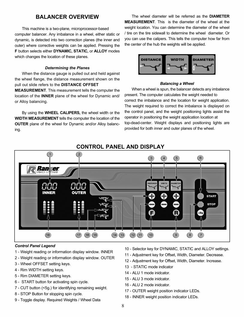
BALANCER OVERVIEW
This machine is a two-plane, microprocessor-based computer balancer. Any imbalance in a wheel, either static or dynamic, is detected into two correction planes (the inner and outer) where corrective weights can be applied. Pressing the F button selects either DYNAMIC, STATIC, or ALLOY modes which changes the location of these planes.
Determining the Planes When the distance gauge is pulled out and held against the wheel flange, the distance measurement shown on the pull out slide refers to the DISTANCE OFFSET MEASUREMENT. This measurement tells the computer the location of the INNER plane of the wheel for Dynamic and/or Alloy balancing.
By using the WHEEL CALIPERS, the wheel width or the WIDTH MEASUREMENT tells the computer the location of the OUTER plane of the wheel for Dynamic and/or Alloy balanc-ing.
The wheel diameter will be referred as the DIAMETER MEASUREMENT. This is the diameter of the wheel at the weight location. You can determine the diameter of the wheel / tire on the tire sidewall to determine the wheel diameter. Or you can use the calipers. This tells the computer how far from the center of the hub the weights will be applied.
Balancing a Wheel When a wheel is spun, the balancer detects any imbalance present. The computer calculates the weight needed to correct the imbalance and the location for weight application. The weight required to correct the imbalance is displayed on the control panel, and the weight positioning lights assist the operator in positioning the weight application location at top-dead-center. Weight displays and positioning lights are provided for both inner and outer planes of the wheel.
CONTROL PANEL AND DISPLAY
Control Panel Legend1 - Weight reading or information display window. INNER2 - Weight reading or information display window. OUTER3 - Wheel OFFSET setting keys.4 - Rim WIDTH setting keys.5 - Rim DIAMETER setting keys.6 - START button for activating spin cycle. 7 - CUT button (<5g.) for identifying remaining weight.8 - STOP Button for stopping spin cycle.9 - Toggle display. Required Weights / Wheel Data
10 - Selector key for DYNAMIC, STATIC and ALLOY settings.11 - Adjustment key for Offset, Width, Diameter. Decrease.12 - Adjustment key for Offset, Width, Diameter. Increase.13 - STATIC mode indicator14 - ALU 1 mode inidcator.15 - ALU 3 mode inidcator.16 - ALU 2 mode inidcator.17 - OUTER weight position indicator LEDs. 18 - INNER weight position indicator LEDs.

9
SELECTING WEIGHT POSITIONS FOR DIFFERENT WHEEL TYPES
Prior to balancing, a specific FUNCTION must be chosen for each particular wheel. The function settings automatically compensate weight location requirements for a particular wheel type. These settings can be selected by depressing the F button.
DYNAMIC (No Symbol Illuminated)For balancing standard steel or alloy wheels using clip-on weights attached to inner and outer wheel edges.
StaticThis function is used if weights can only be mounted on a single plane of the wheel.
ALU1This function is used if stick-on weights are to be mounted to both inner plane and outer planes of the wheel.
ALU2This function is used if stick-on /clip on weights are to be mounted to the inner edges and stick on weights are to be mounted on the center planes of the wheel.
ALU3This function is used if stick-on weights are to be mounted to the inner plane of the wheel and clip-on or stick weights are to be mounted to the outer edge of the wheel.
GRAM / OUNCE SELECTION
This machine is capable of registering GRAM or OUNCE readings. To select either GRAM or OUNCE settings, follow the procedures below.
1. First press the “STOP” button.
Then press the Distance “+” and “-” Button at the same time. The weight readings will change in the INNER and OUTER windows to register the applicable setting.
NOTE:When set to Ounces or Inches the displayed
values contains a decimal point.
MM / INCH SELECTION“L” SETTING / WHEEL WIDTH
To select either MM or INCH measurement reading for the “L” WHEEL WIDTH setting, follow the procedures below.
1. First press the “STOP” button.
Then press the WIDTH “+” and “-” Button at the same time. The weight readings will change in the INNER and OUTER windows to register the applicable setting.
NOTE:When set to Ounces or Inches the displayed
values contains a decimal point.
MM / INCH SELECTION“dia” SETTING / WHEEL DIAMETER
To select either MM or INCH measurement reading for the “dia” WHEEL DIAMETER setting, follow the procedures below.
1. First press the “STOP” button.
Then press the DIAMETER “+” and “-” Button at the same time. The weight readings will change in the INNER and OUTER windows to register the applicable set-ting.
NOTE:When set to Ounces or Inches the displayed
values contains a decimal point.

10
MOUNTING WHEELS
Select the most appropriate mounting method for the wheel you are balancing. Using the proper method ensures secure mounting, accurate displays and safe balancer operation. It also prevents damage to the wheel. On most wheels, the inner side of the wheel hub usually has the most uniform surface for wheel balancing. Always center the wheel by the most uniformly shaped side of the hub to achieve the most accurate balance.
Regardless of mounting type, always make sure that the wheel is forced firmly against the arbor faceplate and that the Quick-Nut engages the threaded arbor for at least four complete turns. To assist in centering the wheel properly, rotate the wheel on the arbor while tightening the Quick-Nut.
CAUTION! DAMAGE CAUSED BY STRIKING OR HITTING THE
QUICK-NUT WITH A HAMMER, TIRE IRON OR HEAVY OBJECT IS NOT COVERED UNDER WARRANTY!
Front Cone Mounting
Front Cone Mounting is the most accurate method
1. Select the cone that best fits the center hole in the wheel.
2. Lift the wheel onto the arbor and slide it back against the arbor faceplate.
3. Slide the cone onto the arbor and into the center of the wheel. Then lift the tire to seat the cone in the center hole.
4. Spin the Quick-Nut (without the pressure cup) onto the arbor. Tighten it securely against the cone.
Rear Cone Mounting
The wheel is centered on a cone from the inner side of the hub.
1. Place the cone spring on the arbor with the large end towards the balancer.
2. Select the cone that best fits the center hole in the wheel. Slide the cone onto the arbor with the large end towards the spring.
3. Lift the wheel onto the arbor and center it on the cone.
4. Attach the pressure cup to the Quick-Nut and spin the assembly onto the arbor. Tighten securely.

11
Dual Cone Mounting
Some aftermarket or OEM performance wheels have a center hole that is deep enough to allow the use of two cones to mount it to the threaded shaft. The factory recom-mends that dual cone mounting is used in this situation. The cones must not contact each other and a correct cone combination is critical to correctly mount a tire using this method. (Extra centering cones are available though Ranger Products)
1. Slide the Spring onto the Arbor.
2. Select the cone combination that best fits both sides of the center hole in the wheel. (Note: You may need two cones that are identical in size)
3. Place the rear cone on the arbor and against the Spring.
4. Lift the wheel onto the arbor and slide it back against the rear cone.
5. Place the front cone on the arbor and slide it into the center hole of the wheel.
6. Spin the quick nut (without the pressure cup) onto the arbor. Tighten securely.

12
BALANCING INSTRUCTIONS
1. First determine which mounting method you will use for the wheel.
2. Select a centering / mounting cone that best fits the center hole of the wheel.
3. After installing the necessary mounting hardware, lift the wheel onto the threaded shaft and slide it back against the arbor hub. It will be necessary to lift the wheel slightly when positioning the cone in the center of the wheel hole.
CAUTION! DAMAGE CAUSED BY STRIKING OR HITTING THE QUICK-NUT WITH HAMMER, TIRE IRON OR HEAVY
OBJECT IS NOT COVERED UNDER WARRANTY!
4. While holding the wheel and hardware in position, thread the Quick-Nut over the arbor and secure tightly. Never hammer or hit the Quick-Nut to tighten.
WARNING!
Always make sure that the Quick-Nut engages the arbor threads by at least four (4) full turns. It helps to spin the wheel while at the same time tightening the Quick-Nut.
Never exceed weight capacity of balancer!Never hammer or strike the Quick-Nut to tighten.
CAUTION! DAMAGE CAUSED BY STRIKING OR HITTING THE QUICK-NUT WITH HAMMER, TIRE IRON OR HEAVY
OBJECT IS NOT COVERED UNDER WARRANTY!
WARNING!
Do not attempt to balance wheels that are larger than the machine was designed for.
Inputting Wheel Data
Prior to balancing any wheel, specific data relating to that particular wheel must be entered into the computer. If the data displayed on the screen does not match that of the wheel you are attempting to balance then the wheel will not be accurately balanced. The three data requirements are; “-A-” Offset, “-L-” Width and “-d-” Diameter.
WHEEL DATA KEY BOARD
dis - Wheel Offset
This is the distance between the side of the balancer and the inner edge of the wheel. To enter Wheel Offset data refer to the instructions below.
1. Turn the machine on.
2. Press the + or - button below Distance .
3. -A- will be displayed in the INNER window.

13
4. Pull the index arm out from the side of the machine until the tip touches the inner edge of the wheel.
5. Read the offset measurement as displayed on the scale directly on top of the index arm. Press the corresponding + - buttons below to enter the correct data.
L - Wheel Width
This is the width of the wheel at the inner edges. This distance is measured with the calipers. To enter Wheel Width data refer to the instructions below.
1. Position the calipers over the wheel and touch the tips against the wheel edges.
2. Read the measurement for Wheel Width shown on the calipers. (Use the proper scale for Width)
3. Press the + or - button below .
4. -L- will be displayed in the INNER window.
5. Press the corresponding + - buttons to enter the correct data. IMPORTANT NOTE: The standard setting for this operation is shown in INCHES. If metric is desired, new calipers with metric readings will have to replace the calipers that accompanied the unit. (See page 10 for changing “L” reading to MM or INCH setting.)
“dia” - Wheel Diameter
This is the diameter of the wheel at the rim flanges. This measurement can be read on the tire sidewall. Or mea-sured. To enter Wheel Diameter data, refer to the instruc-tions below.
1. Read the diameter of the wheel as shown on the tire sidewall. Or use the Calipers to measure the wheel diam-eter. (Use the proper scale for Wheel Diameter)
2. Press the + or - button adjacent to .
3. -d- will be displayed in the INNER window.
4. Press the corresponding + - buttons to enter the correct data. (See page 10 for changing “d” reading to MM or INCH setting.)
Spin Mode / DYNAMIC, AL1, AL2, AL3, AL4
1. Once the correct wheel data and FUNCTION have been programmed, lower the hood to begin the spin mode.
WARNING!
Before initiating the spin sequence, make sure that the Quick-Nut is secure and engaged on the arbor
threads by at least four (4) full turns. Never hammer or hit the Quick-Nut to tighten.
CAUTION! DAMAGE CAUSED BY STRIKING OR HITTING THE QUICK-NUT WITH HAMMER, TIRE IRON OR HEAVY
OBJECT IS NOT COVERED UNDER WARRANTY!

14
2. After the hood is lowered, or the START button is depressed, the wheel will spin for approximately six sec-onds then stop automatically.
3. After the wheel stops, weight readings for each side of the wheel (INNER and OUTER) will appear in the center display screen.
4. Turn the wheel by hand until the weight position indicator lights on the side marked INNER are FULLY ILLUMINATED. This indicates the position specified by the balancer for the inner weight position.
5. Attach the specified weight for the appropriate PLANE position at top-dead-center.
NOTE: To hold the wheel in position when installing
weights, press down on the TIRE STOP PEDAL located on the right side of the machine.
NOTE:All weight positions are located at TOP-DEAD-CENTER. The more accurate you are in selecting the exact weight and position, the more accurate
the wheel will be balanced.
6. After the INNER weight is properly installed, turn the wheel by hand until the weight position indicator lights on the side marked OUTER are fully illuminated. This indicates the position specified by the balancer for the OUTER weight position.
7. Attach the specified weight for the appropriate PLANE position at top-dead-center.
NOTE:
If you are experiencing balancing problems per-form the Weight Location Verification Test found on page 17 of this manual. If the balancer fails this test perform the calibration procedures located on the
same page.
NOTE:
It is recommended that the Weight Location Verification Test be performed on a monthly basis.

15
Spin Mode / STATIC
This function is used if weights can only be mounted on a single plane of the wheel.
1. Once the correct wheel data has been programmed, lower the hood to begin the spin mode.
2. After the hood is lowered, or the START button is depressed, the wheel will spin for approximately six sec-onds then stop automatically.
3. After the wheel stops, a weight reading will appear in both center display screens. The weight reading will appear the same in both screens.
4. Turn the wheel by hand until the weight position indicator lights on the side marked INNER are fully illuminated. The OUTER indicator lights will not illuminate.
5. This indicates the position specified by the balancer for the desired weight location on the chosen PLANE.
6. Attach the specified weight on the PLANE of the wheel at top-dead-center.
Rechecking the Balance
After installing the weights in the proper positions, lower the hood or press START to begin the spin mode. The weight display windows should display 0 -- 0 to indicate a perfect balance.
If the balancer indicates that an additional weight is required in the same position as the first weight, then the first weight installed was not heavy enough. Install a new weight or add additional weight to the same area. Re-spin the wheel and check again.
If the balancer indicates that an additional weight is required opposite the position as the first weight, then the first weight installed was too heavy. Correct the first weight and re-spin the wheel.
If the balancer indicates that an additional weight is required in a different position as the first weight, then the first weight was installed in the wrong position. Correct the first weight and re-spin the wheel and check again.
IDENTIFYING REMAINING WEIGHTYour balancer is set to read 0 -- 0 if the wheel is balanced within 5 grams on either side. If you wish to see what remainder is left on each side ( less than 5 grams ) press the CUT button.
After pressing the CUT button, residual weight readings will appear in the display windows.
STOP BUTTON
The STOP button IS an emergency stop but-ton. It will immediately shut down the shaft and wheel rotation. For emergency situa-tions that require immediate shutdown of rota-tion, it is recommended that you use the STOP button and the TIRE STOP PEDAL located on the right-front side of the unit.
After Balance Vibration ProblemsIf vibration is still present after balancing the wheels and driving the vehicle on smooth pavement remove the wheels and recheck the balance. If a wheel is out of balance the cause may be:
1. A weight has come off the wheel. Remove the other weights from the wheel and rebalance.
2. Tire slippage on the wheel. Remove and remount the tire using proper tire lubricant and inflate to 40 PSI. Do not over-inflate. Rebalance the wheel and reduce air pressure to recommended PSI.
3. Stones or other foreign objects caught in the tire tread.
Remove the objects and repair tire as necessary. Check and rebalance if needed. If the balancer still indicates the wheels are balanced to within 5 grams on both inner and outer displays, the problem is not in the balance of the wheels. Check the following possible sources of vibration:
1. Tire pressure. Bring all tires up to the recommended PSI.
2. Radial or lateral runout in the tire or wheel. Replace the damaged part.
3. Foreign material inside the tire. Remove the tire from the wheel, remove the material, and remount. Remove wheel weights and rebalance the wheel.
4. Imbalanced wheel covers or trim rings. Remove the wheel covers or trim rings and test drive, balance the wheel with the wheel cover or trim ring attached to the wheel.
5. Incorrectly mounted wheel. Remount correctly.
6. Damaged wheel bolt holes. Replace wheel.
7. Worn universal joints. Replace as required.
8. Drive shaft imbalanced or damaged. Balance, repair, or replace.
9. Imbalanced brake rotor(s) or drum(s).
10. Suspension out of alignment. Align the vehicle andreplace any damaged or worn parts.

16
TROUBLE SHOOTING GUIDE. Perform the following checks if you are experiencing balancing problems.
PROPER INSTALLATION / ASSEMBLYConfirm that the balancer is bolted down. Confirm the location and alignment of the witness marks on the Face Plate and Shaft Assembly. (See Page 7.)
CALIBRATIONIt is recommended that the Weight Location Verification Test be performed on a monthly basis following the procedure found on the following page.
The calibration should be performed with a 14” or 15” steel wheel with a tire.
NOTE: It is good practice to keep a known good tire and 14” or 15” rim combination to use as a calibration /refer-ence tire to assist in any trouble shooting.
Ensure that the calibration weight used is a 100 gram or 3.5 oz weight and that is mounted correctly during the calibration procedure.
PROPER MOUNTINGThe recommended method for mounting of a tire and wheel for calibration and balancing is the Front Cone Mounting. (Using the cone to secure against the flange) for the most security and stability. (Rear Cone Mounting uses the Pressure Cup assembly.) (Extra centering cones are available though Ranger Products.)
If any the above conditions were found, the condition must be remedied and the balancer must be re-calibrated.

17
WEIGHT LOCATION VERIFICATION TEST
NOTE:Before performing the Weight Location Verification Test, make sure the balancer is bolted down and/or rigid to the floor and that the shaft and centering cones are clean and undamaged. Even the slightest dirt or damage can cause inaccurate readings. PAY CLOSE ATTENTION to the following procedure. If not followed correctly, the balancer will not perform
accurately.This balancer should be checked every 30 days.
NOTE:A standard 14” steel wheel and tire balanced to within 5 grams on either inner or outer with minimal wear or damage to the tire or wheel is required for
this procedure.
1. Balance an average size tire and wheel to “00”—“00”
2. With the correct parameters DIST, DIA, and WIDTH programmed into the balancer add a 100 gram wheel weight to the outer edge of the wheel.
3. Press the Start button (close Hood). Wheel will spin and stop.
4. The balancer should call for 100 grams on the outer indicator and “00”on the inner indicator.
5. Rotate the wheel until all the LEDs on the outer indica-tor are lit.
6. The 100 gram wheel weight should be at 6(o clock) Bottom Dead Center.
7. Remove the 100 gram wheel weight from the outer edge of the wheel.
8. Install the 100 gram wheel weight on the inner edge of the wheel.
9. Press the Start button. Wheel will spin and stop.
10. The balancer should call for 100 grams on the inner indicator and “00” on the outer indicator.
11. Rotate the wheel until all the LEDs are lit on the inner indicator are lit.
The 100 gram wheel weight should be at (6 o’clock) Bottom Dead Center.
If the location is not as Bottom Dead Center (6 o’clock), please contact the Ranger Products Customer Service Department.
BendPak Inc. / Ranger Products1645 Lemonwood Dr.,
Santa Paula, CA. 93060 1-805-933-99701-800-253-2363
www.rangerproducts.comwww.bendpak.com
SELF-CALIBRATION PROCEDURE1. Turn on the power. The display will show USA 511.
2. Select a centering / mounting cone that best fits the center hole of the wheel.
NOTE:A standard 14” steel wheel and tire with minimal wear or
damage to either is recommended for this procedure.
3. Lift the wheel onto the arbor and slide it back against the arbor hub.
4. Slide the cone over the arbor and into the center hole of the wheel. It will be necessary to lift the wheel slightly.
5. While holding the wheel and cone in position, thread the Quick-Nut over the arbor and secure tightly.
5. Enter the correct wheel data. (Refer to page 12.) 7. Press and hold the “R” and “START” button until the Weight Indicator lights stop flashing. The screen will then display “CAL CAL”
8. Close the hood and/or press START to begin the calibra-tion.
9. The wheel will spin for approximately 6 seconds then stop. “Add 100” will be displayed if Grams is selected or “ADD 3.50” if OZ is selected.
10. Place one 100 gram weight (included with balancer) on the outer edge of the rim.
11. Close the hood and press the START button. The wheel will spin for approximately 6 seconds and “END Cal” will be displayed.
NOTE:It is a good idea to keep the known good “calibration tire”
set up for the monthly calibration procedure.
18
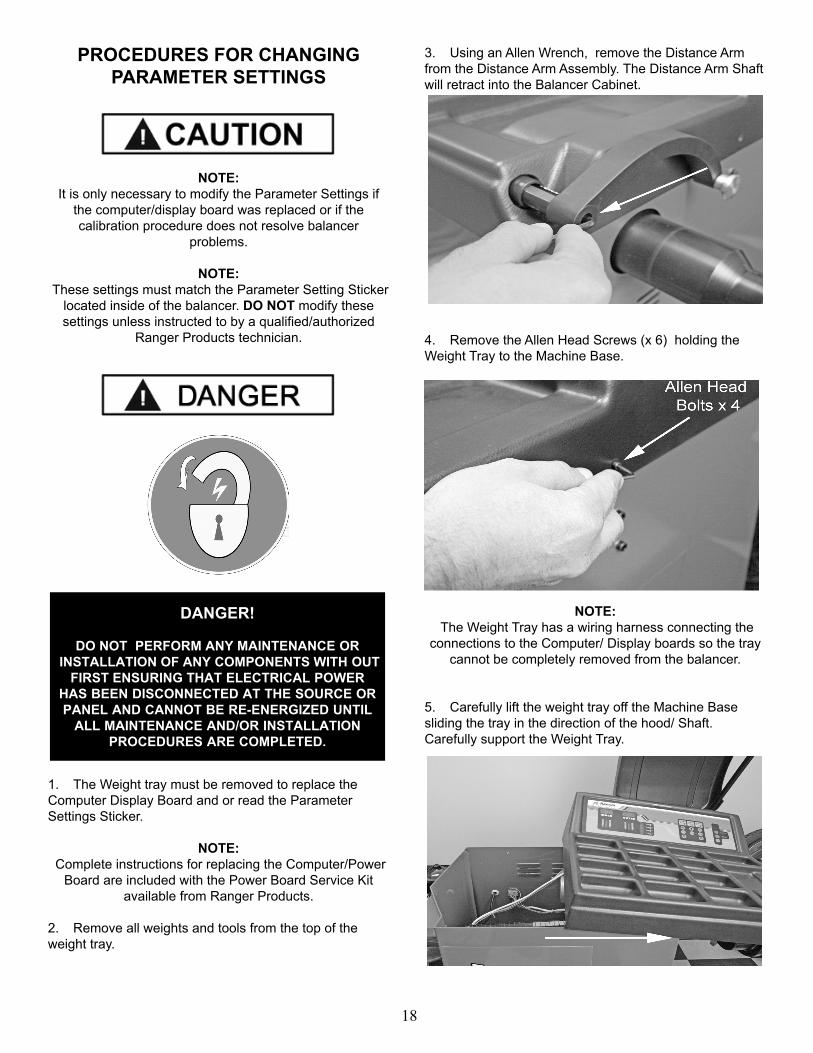
PROCEDURES FOR CHANGING PARAMETER SETTINGS
NOTE: It is only necessary to modify the Parameter Settings if
the computer/display board was replaced or if the calibration procedure does not resolve balancer
problems.
NOTE: These settings must match the Parameter Setting Sticker
located inside of the balancer. DO NOT modify these settings unless instructed to by a qualified/authorized
Ranger Products technician.
1. The Weight tray must be removed to replace the Computer Display Board and or read the Parameter Settings Sticker.
NOTE: Complete instructions for replacing the Computer/Power
Board are included with the Power Board Service Kit available from Ranger Products.
2. Remove all weights and tools from the top of the weight tray.
3. Using an Allen Wrench, remove the Distance Arm from the Distance Arm Assembly. The Distance Arm Shaft will retract into the Balancer Cabinet.
4. Remove the Allen Head Screws (x 6) holding the Weight Tray to the Machine Base.
NOTE: The Weight Tray has a wiring harness connecting the
connections to the Computer/ Display boards so the tray cannot be completely removed from the balancer.
5. Carefully lift the weight tray off the Machine Base sliding the tray in the direction of the hood/ Shaft. Carefully support the Weight Tray.
DANGER!
DO NOT PERFORM ANY MAINTENANCE OR INSTALLATION OF ANY COMPONENTS WITH OUT
FIRST ENSURING THAT ELECTRICAL POWER HAS BEEN DISCONNECTED AT THE SOURCE OR PANEL AND CANNOT BE RE-ENERGIZED UNTIL
ALL MAINTENANCE AND/OR INSTALLATION PROCEDURES ARE COMPLETED.

19
6. Carefully support the Weight Tray while noting the Parameter Setting Values located on the Parameter Settings Sticker located on the inside wall of the front panel of the machine.
7. Note the Parameter Setting Values before reassembly, they will be needed after cover is closed.
8. Reassemble the Weight Tray and Distance Arm and proceed to resetting the Parameter Settings.

20
RESETTING PARAMETER SETTINGS
1. Press and hold the R button and the
Start button at the same time until the
weight position indicators stop flashing.
2. The Screen should now display “CAL CAL”.
3. Press -, below , then + below
and then F .
NOTE:These buttons must be pressed in sequence otherwise
you will bypass the first parameter setting.
4. The Screen should now display “dIS” on the Inner and a 3 digit number on the Outer.
5. Verify that the “dIS’ setting matches the values shown on the Parameter Settings Sticker located on the inside of the balancer.
6. Press the + or - button below to modifythe values to match the values shown on the Parameter Settings Sticker.
7. When checking/modifying the “dIS” setting is
complete, press Distance + button below to move on to the next parameter setting.
NOTE:Once you move on to the next parameter setting, you must restart this procedure if you would like
to edit the dIS value again.
8. The Screen should now display “In.” on the Inner and a 3 digit number on the Outer.
9. Verify that the In.- setting matches the Parameter Settings Sticker located on the inside of the balancer.
10. Press the + or - button below to modifythe values to match the values shown on the Parameter Settings Sticker.
11. When checking/modifying the dIS setting is complete,
press + button below to move on to the next parameter setting.
NOTE:Once you move on to the next parameter setting, you must restart this procedure if you would like
to edit the In.- value again.
12. The Screen should now display “SFA” on the Inner and a 3 digit number on the Outer.
13. Verify that the SFA setting matches the Parameter Settings Sticker located on the inside of the balancer.

21
14. Press the + or - button below to modifythe values to match the values shown on the Parameter Settings Sticker.
15. When checking/modifying the SFA setting is complete,
press Distance + button below to move on tothe next parameter setting.
16. Once you are done checking/modifying the SFA setting, press Distance + to move save the changes.
NOTE:Once you move on to the next parameter setting, you must restart this procedure if you would like
to edit the SFA value again.

22
Err.
-1-
1. B
alan
cer S
haft
Doe
s N
ot R
otat
e.1.
Che
ck th
e el
ectri
cal c
onne
ctio
n.
2. R
epla
ce th
e P
ower
boa
rd.
3.
Rep
lace
the
Ele
ctric
al M
otor
.E
rr. -2
-1.
A w
heel
is n
ot in
stal
led
on th
e ba
lanc
er.
2.
A w
heel
is in
stal
led
on th
e ba
lanc
er b
ut th
ere
is n
o tir
e.
3.
The
qui
ck n
ut is
not
tigh
t and
/or t
he w
heel
is n
ot c
orre
ctly
ins
talle
d on
the
bala
ncer
.
4.
The
Ele
ctric
al M
otor
bel
t ten
sion
is n
ot c
orre
ct.
1. In
stal
l a w
heel
on
the
bala
ncer
.
2.
Inst
all a
tire
on
the
whe
el.
3.
Rem
ove
the
tire
from
the
bala
ncer
and
re-m
ount
it
cor
rect
ly.
4. A
djus
t the
bel
t ten
sion
for t
he E
lect
rical
Mot
or.
Err.
-3-
1. T
he w
heel
/tire
com
bina
tion
has
to la
rge
of a
n un
bala
nce.
1. R
epos
ition
the
Tire
on
the
Whe
el to
redu
ce th
e
u
nbal
ance
. 2.
Use
a d
iffer
ent T
ire a
nd/o
r Whe
el.
3.
Red
o th
e ca
libra
tion
proc
edur
e.E
rr. -4
-1.
The
whe
el is
rota
ting
coun
ter c
lock
wis
e.
2. T
he w
heel
is ro
tatin
g cl
ockw
ise
and
the
Enc
oder
Boa
rd is
mal
func
tioni
ng.
1. C
heck
the
elec
trica
l con
nect
ions
for t
he E
lect
rical
Mot
or.
2. A
djus
t and
/or R
epla
ce th
e E
ncod
er B
oard
.E
rr. -5
-1.
The
pro
tect
ive
Hoo
d is
Ope
n.1.
Clo
se th
e pr
otec
tive
Hoo
d.E
rr. -6
-N
AN
AE
rr. -7
-1.
The
Com
pute
r/Dis
play
boa
rd m
emor
y w
as c
lear
ed.
1. C
heck
that
the
para
met
er s
ettin
g m
atch
the
stic
ker
lo
cate
d in
side
the
bala
ncer
and
redo
the
fact
ory
cal
ibra
tion.
Err.
-8-
1. 1
00g
wei
ght w
as n
ot a
ttach
ed d
urin
g th
e ca
libra
tion
proc
edur
e.
2. T
he p
iezo
sen
sor(
s) w
ires
are
disc
onne
cted
or i
t is
m
alfu
nctio
ning
.3.
Com
pute
r/Dis
play
boa
rd m
alfu
nctio
n.
1. D
o th
e ca
libra
tion
proc
edur
e an
d at
tach
the
100g
w
eigh
t dur
ing
the
corr
ect s
tep.
2. C
heck
the
elec
trica
l con
nect
ions
for t
he p
iezo
sen
sor(
s).
3. R
epla
ce th
e C
ompu
ter/D
ispl
ay b
oard
.
4. C
onta
ct R
ange
r Pro
duct
s.Fa
iled
Cal
ibra
tion
Che
ck1.
The
whe
el u
sed
for c
alib
ratio
n w
as to
o la
rge.
2. T
he w
heel
use
d fo
r cal
ibra
tion
had
too
larg
e of
an
unba
lanc
e.
3.
The
whe
el d
ata
was
not
ent
ered
cor
rect
ly.
4.
The
SFA
(Loc
atio
n) p
aram
eter
set
ting
is n
ot c
orre
ct.
1. U
se a
bal
ance
d 14
-15
inch
whe
el a
nd re
do th
e
cal
ibra
tion
proc
edur
e.2.
Che
ck th
e w
heel
info
rmat
ion
is e
nter
ed c
orre
ctly
for t
he ti
re y
ou a
re u
sing
for c
alib
ratio
n.3.
Con
tact
Ran
ger P
rodu
cts
for i
nstru
ctio
n to
mod
ify
th
e S
FA (L
ocat
ion)
par
amet
er.
No
Dis
play
1. T
he b
alan
cer i
s tu
rned
off.
2. T
he b
alan
cer h
as n
o po
wer
goi
ng to
it.
3. T
he C
ompu
ter/D
ispl
ay b
oard
is d
efec
tive
1. C
heck
that
the
bala
ncer
is tu
rned
on.
2.
Che
ck th
at th
e yo
ur b
alan
cer i
s co
nnec
ted
to a
live
ele
ctric
al s
ourc
e.3.
Rep
lace
the
Com
pute
r/Dis
play
boa
rd.
No
Wei
ght I
nfor
mat
ion
Dis
play
ed1.
The
pie
zo s
enso
r(s)
wire
s ar
e di
scon
nect
ed o
r it i
s
mal
func
tioni
ng.
2. T
he C
ompu
ter/D
ispl
ay b
oard
has
lost
the
para
met
er s
ettin
gs.
1. C
heck
the
elec
trica
l con
nect
ions
for t
he p
iezo
sen
sor(
s).
2. C
heck
that
the
para
met
er s
ettin
g m
atch
the
stic
ker
lo
cate
d in
side
the
bala
ncer
edi
t the
m if
nec
essa
ry.

23

24

25

26
DRAWING NO.
DESCRIPTION
101 Membrane Switch102 Plastic Tray Cover103 Wheel Guard104 Wheel Guard Support105 Computer / Display Board106 Voltage Selector Switch107 Shelves108 Hanger109 Power Switch110 Chassis Body111 Hub112 Hub Retaining Screw113 Gauge Sleeve - short114 Gauge Rod115 Gauge sleeve - long116 Measurement Arm117 Measurement Head118 Gauge Spring119 Sensor Vertical Rod120 Sensor Horizontal Rod121 Vertical Sensor122 Horizontal Sensor123 Side Panel124 Spindle Cover125 Encoder/Photo Electricity Board126 Belt127 Motor128 Motor Bracket129 Motor Pulley130 Motor Pulley Key
DRAWING NO.
DESCRIPTION
201 Transformer202 Power Board203 Resistor204 Power Mounting Plate
301 Brake Pad302 Brake pad Spacer303 Brake Bracket304 Spring305 Brake Fixed Plate306 Brake Square Plate307 Tie-rod Head308 Tie-rod309 Brake Connector310 Bushing311 Brake Pedal Connector 312 Brake Pedal313 Square Rod314 Screw Sleeve315 Bolt316 Spring
401 Hood Switch Box Cover402 Hood Switch Box403 Head Pivot Shaft404 Bushing405 Hood Spring406 Snap Ring407 Hood Switch408 Block409 Cam410 Hood Adjustment Screw

27
TIRE AND WHEEL DATA________________________________________________________________________________
________________________________________________________________________________
________________________________________________________________________________
________________________________________________________________________________
________________________________________________________________________________
________________________________________________________________________________
________________________________________________________________________________
________________________________________________________________________________
________________________________________________________________________________
________________________________________________________________________________
________________________________________________________________________________
________________________________________________________________________________
________________________________________________________________________________
________________________________________________________________________________
________________________________________________________________________________
________________________________________________________________________________
________________________________________________________________________________
________________________________________________________________________________
________________________________________________________________________________
________________________________________________________________________________
________________________________________________________________________________
________________________________________________________________________________
________________________________________________________________________________
________________________________________________________________________________

28
For Parts Or ServiceContact:
BendPak Inc. / Ranger Products1645 Lemonwood Dr.
Santa Paula, CA 93060Toll Free 1-800-253-2363
Tel: 1-805-933-9970Fax: 1-805-933-9160
www.bendpak.comwww.rangerproducts.com
p/n# 5900233