Embed Size (px)
Citation preview
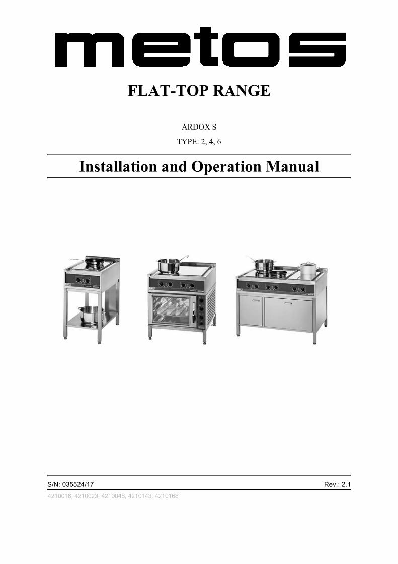
FLAT-TOP RANGE
ARDOX S
TYPE: 2, 4, 6
Installation and Operation Manual
S/N: 035524/17 Rev.: 2.1
4210016, 4210023, 4210048, 4210143, 4210168


2.3.2006 Rev. 2.1
Dear Customer,
Congratulations on deciding to choose our appliance for your kitchen activities. Youmade an excellent choice. We will do our best to make you a satisfied customer like thou-sands of customers we have around the world.
Please read this manual carefully. You will learn correct, safe and efficient working meth-ods in order to get the best possible benefit from the appliance. The instructions and hintsin this manual will give you a quick and easy start, and you will soon note how nice it isto use this equipment.
All rights are reserved for technical changes.
You will find the main technical data on the rating plate fixed to the appliance. When youneed service or technical help, please let us know the serial number shown on the ratingplate. This will make it easier to provide you with correct service.
For your convenience, space is provided below for you to record your local service con-tact information.
Service phone number:...............................................................................................
Contact person:....................................................................................................................
2.3.2006 Rev. 2.1
2.3.2006 Rev.
1. General .......................................................................................................... 11.1 Symbols used in the manual .......................................................................................... 11.2 Symbols used on the appliance ...................................................................................... 11.3 Checking the relationship of the appliance and the manual .......................................... 1
2. Safety .............................................................................................................. 22.1 Safe use of the appliance ............................................................................................... 22.2 Disposal of the appliance ............................................................................................... 2
3. Functional description .................................................................................. 33.1 Application of the appliance .......................................................................................... 3
3.1.1 Prohibited use ........................................................................................................ 33.2 Operating principle and construction ............................................................................ 3
4. Operation instructions ................................................................................. 54.1 Before use ...................................................................................................................... 54.2 Operation ....................................................................................................................... 5
4.2.1 Selecting cookware ................................................................................................ 54.2.2 Using the range ...................................................................................................... 5
4.3 After use ........................................................................................................................ 64.3.1 Cleaning ................................................................................................................. 64.3.2 Service ................................................................................................................... 6
5. Installation ..................................................................................................... 75.1 General .......................................................................................................................... 75.2 Transporting and unpacking the range .......................................................................... 75.3 Positioning the range ..................................................................................................... 75.4 Electricity connections .................................................................................................. 75.5 Test-run .......................................................................................................................... 8
6. Troubleshooting ............................................................................................ 9
7. Spare parts .................................................................................................. 117.1 Voltage codes .............................................................................................................. 137.2 Product codes ............................................................................................................... 13
8. Technical specifications .............................................................................. 23

2.3.2006 Rev.
2.3.2006 Rev. 2.1General
1. General
Carefully read the instructions in this manual as they contain important information re-garding proper, efficient and safe installation, use and maintenance of the appliance.
Keep this manual in a safe place for eventual use by other operators of the appliance.
The installation of this appliance must be carried out in accordance with the manufactur-er’s instructions and following local regulations. The connection of the appliance to theelectric and water supply must be carried out by qualified persons only.
Persons using this appliance should be specifically trained in its operation.
Switch off the appliance in case of failure or malfunction. The periodical function checksrequested in the manual must be carried out according to the instructions. Have the appli-ance serviced by a technically qualified person authorized by the manufacturer and usingoriginal spare parts.
Not complying with the above may put the safety of the appliance in danger.
1.1 Symbols used in the manual
This symbol informs about a situation where a safety risk might be at hand. Given instruc-tions are mandatory in order to prevent injury.
This symbol informs about the right way to perform in order to prevent bad results, appli-ance damage or hazardous situations.
This symbol informs about recommendations and hints that help to get the best perform-ance out of the appliance.
1.2 Symbols used on the appliance
This symbol on a part informs about electrical terminals behind the part. The removal ofthe part must be carried out by qualified persons only.
1.3 Checking the relationship of the appliance and the manual
The rating plate of the appliance indicates the serial number of the appliance. If the man-uals are missing, it is possible to order new ones from the manufacturer or the local rep-resentative. When ordering new manuals it is essential to quote the serial number shownon the rating plate.
1
2.3.2006 Rev. 2.1Safety
2. Safety
2.1 Safe use of the appliance
Because the range is a heated appliance that has hot surfaces during normal use, the fol-lowing warnings and instructions must be followed in order to avoid burns:
During long-time operation even the frame surrounding the flat top gets hot.
The capability of the flat top to store and even out the heat also keeps it hot for a long timeafter switching it off.
For safe handling of cookware on the cooking top, always use heat protective gloves.
Do not leave the range on for long periods totally without supervision.
2.2 Disposal of the appliance
Once the range has reached the end of its useful life, it must be disposed of in compliancewith local rules and regulations. The best way of dealing with or recycling any substanceswhich potentially have an adverse impact on the environment is to dispose of themthrough a proper problem waste company.
2
2.3.2006 Rev. 2.1Functional description
3. Functional description
3.1 Application of the appliance
The Ardox range is intended for preparing different kinds of foodstuffs using cookware.
3.1.1 Prohibited use
Use of the appliance for any other purposes than that stated above is prohibited.
Preparing food directly on the flat top without cookware is prohibited.
The manufacturer shall not be held liable for any situations which may arise from failureto comply with the warnings and instructions given in this manual.
3.2 Operating principle and construction
In addition to a single range, there are combinations of a range and an oven (Chef 22 orChef 24) or a range and a proving cabinet (Chef 20). This manual covers the Ardox range,while Chef 22, Chef 24 and Chef 20 have their own manuals.
The range is equipped with two cooking zones.
The range is equipped with four cooking zones.
The range is equipped with six cooking zones.
3
2.3.2006 Rev. 2.1Functional description
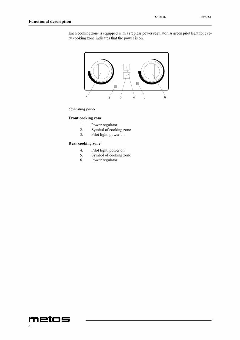
Each cooking zone is equipped with a stepless power regulator. A green pilot light for eve-ry cooking zone indicates that the power is on.
Operating panel
Front cooking zone
1. Power regulator2. Symbol of cooking zone3. Pilot light, power on
Rear cooking zone
4. Pilot light, power on5. Symbol of cooking zone6. Power regulator
1 2 3 4 5 6
4
2.3.2006 Rev. 2.1Operation instructions
4. Operation instructions
4.1 Before use
There is a slight smell of metal and thermal insulation when the range is heated for thefirst time. This is completely normal and disappears by heating the range. Before usingthe range for the first time, heat it at maximum temperature until the smell disappears.
4.2 Operation
4.2.1 Selecting cookware
You can use the same cookware on the flat-top range as on the conventional range.
To get the best benefit from the range as well as from the cookware observe the following:
• Always lift pans, do not drag.• Use good quality flat-based cookware.• Wait for pans to cool before putting them in cold water.• Always ensure that pans have clean, dry bases before use.• Ensure that pan handles are positioned safely and away from heat sources.• Always use pan lids except when frying.
Remember that good quality pans retain heat well, so generally only low or medium heatis necessary.
4.2.2 Using the range
Ranges intended for use aboard ships are equipped with a kettle support. Using a rangewithout the kettle support is prohibited.
During installation a mains switch may have been fitted near the range, often on a wallnearby. Check that the mains switch is in the ON position.
The range is controlled with power regulators and pilot lights (see Figure “Operating pan-el”). Start cooking on maximum power (turn the knob 3/4 rounds clockwise). When boil-ing starts decrease the power as needed.
Do not leave the cooking zone on without any load because it then overheats, which con-siderably decreases its operating life. By turning the cooking zone off when not neededenergy is also saved and a cooler working environment is achieved.
5
2.3.2006 Rev. 2.1Operation instructions
If there are longer interruptions in the electricity distribution, all power regulators of therange should be set to the 0 position. This should be done in order to prevent unexpectedstart-up of the range when the electricity distribution is restored.
4.3 After use
4.3.1 Cleaning
Use of a hose or pressure washer to clean the range is forbidden.
Before cleaning the range, please remember that it remains hot for a long time after use.
In all cleaning prefer chemical cleaning methods rather than mechanical rubbing.
Ranges are electrical appliances, which means that there are restrictions regarding clean-ing them with water. Clean the outside of the range with a damp cloth only to avoid watergetting into the air inlets.
When cleaning the surfaces of the range, use a slightly alkaline detergent (pH 8-10) dilut-ed in water according to instructions (for instance a detergent intended for oven cleaning).
Cleaning is very easy if possible spillovers are removed immediately with a damp cloth.
Sugar and mixes containing much sugar must be removed immediately, because later re-moving will be laborious.
A clean cooking top ensures efficient heat transfer to the cookware. Cooking is then fastand the operating life of the heating elements is extended.
4.3.2 Service
This appliance does not contain parts which can be serviced by the user. Maintenancemust be carried out by an authorised agent.
In the event of fault or malfunction, switch the appliance off at the mains. Contact an agentauthorised by the manufacturer and use original spare parts.
6
2.3.2006 Rev. 2.1Installation
5. Installation
5.1 General
The installation of the appliance must be carried out in accordance with the manufactur-er’s instructions and in compliance with local rules and regulations. These instructionsmust be used together with the installation drawing.
This appliance may be connected to the mains electricity by qualified persons only.
5.2 Transporting and unpacking the range
The range is best transported in its own package, which protects it from outside damage.If it is necessary to unpack the range, possible lifting must be done from the bottom frameusing suitable spacers of wood. To prevent damage, the top of the range must not be usedas a worktop on the construction site or during installation.
5.3 Positioning the range
Because the temperature of the cooking zone accidentally forgotten on without a pan mayreach even 350°C, it is mandatory to follow local fire safety regulations when installingthe range.
When installing the range, care should be given to ensure that there is a free passage ofcooling air around the range and that there are no other sources of heat near the coolingvents.
It is recommended that the range is placed under a hood because of the steam arising dur-ing cooking.
The range is positioned in the installation place and adjusted in a horizontal position fromthe adjustable legs.
When the range is in the right place and in a horizontal position, fix it firmly to the floor.Models for use on land are fixed by the plates on the back legs and ranges intended foruse on ships by the plates on each leg.
5.4 Electricity connections
Should maintenance require the appliance to be tested before all the protective coveringsare in place, please be particularly careful of the moving parts inside the casing as well asof live parts.
7
2.3.2006 Rev. 2.1Installation
To facilitate future maintenance and to increase safety, install a separate disconnectionswitch for the range in the immediate vicinity of the appliance. The switch should discon-nect the appliance completely from the mains supply.
The supply cable inlet is in the back right-hand corner of the range and the connectionpoint inside the range.
Observe the range movement (200 mm) when installing the supply cable on rangesequipped with height adjustment.
The top deck needs to be open to connect the range to the mains. Unfix the screws at thefront part of the flat top (parts 170 and 180) and raise the deck up.
Be cautious when opening the deck because of its weight and always lock the deck intothe open position with the fixing rod.
All information needed to connect the range is to be found on the name plate, the connec-tion diagram and the installation drawing.
5.5 Test-run
Please read the safety and operation instructions as well as the functional description ofthe appliance before testing the range.
Test the range once it has been connected to the mains electricity.
Check that every cooking zone heats up and the corresponding pilot light turns on whenthe zone is switched on with the power regulator.
Close and fasten the top deck.
8
2.3.2006 Rev. 2.1Troubleshooting
6. Troubleshooting
If the appliance fails to work, check to ensure that
• it has been used according to the instructions• all removable parts are in place• the main power switch (usually on a wall or in the immediate vicinity of the appli-
ance) is in the ON position• the fuses (overload protection) have not blown in the fuse box. Ask a qualified per-
son to check overload protection.
Should the range still not work, contact an authorised agent. Before contact, make sureyou have at hand the appliance type and serial number to be found on the name plate onthe right front corner of the appliance.
This appliance does not contain parts which can be serviced by the user. Maintenancemust be carried out by an authorised agent.
9

2.3.2006 Rev. 2.1Troubleshooting
10
2.3.2006 Rev. 2.1Spare parts
7. Spare parts
General parts ........................................ 15
General parts ........................................ 17
General parts ........................................ 19
Height-adjustable stand......................21
11

2.3.2006 Rev. 2.1Spare parts
12
2.3.2006 Rev. 2.1Spare parts
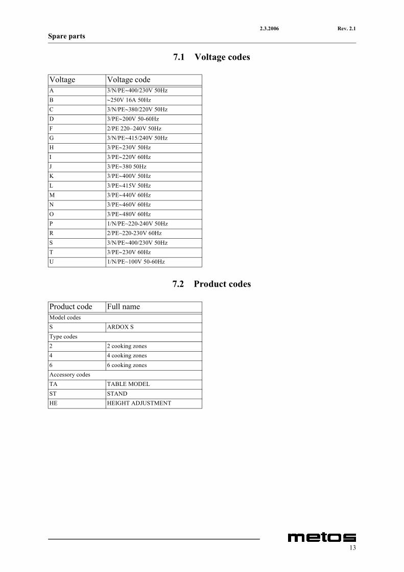
7.1 Voltage codes
7.2 Product codes
Voltage Voltage codeA 3/N/PE∼400/230V 50HzB ∼250V 16A 50HzC 3/N/PE∼380/220V 50HzD 3/PE∼200V 50-60HzF 2/PE 220−240V 50HzG 3/N/PE∼415/240V 50HzH 3/PE∼230V 50HzI 3/PE∼220V 60HzJ 3/PE∼380 50HzK 3/PE∼400V 50HzL 3/PE∼415V 50HzM 3/PE∼440V 60HzN 3/PE∼460V 60HzO 3/PE∼480V 60HzP 1/N/PE~220-240V 50HzR 2/PE~220-230V 60HzS 3/N/PE∼400/230V 50HzT 3/PE∼230V 60HzU 1/N/PE~100V 50-60Hz
Product code Full nameModel codesS ARDOX SType codes2 2 cooking zones4 4 cooking zones6 6 cooking zonesAccessory codesTA TABLE MODELST STANDHE HEIGHT ADJUSTMENT
13
2.3.2006 Rev. 2.1Spare parts
14
2.3.2006 Rev. 2.1Spare parts
S=ARDOX S2=2, 4=4, 6=6TA=TABLE MODEL, ST=STAND, HE=HEIGHT ADJUSTMENTA=3/N/PE∼400/230V 50Hz, G=3/N/PE∼415/240V 50Hz, H=3/PE∼230V 50Hz, I=3/PE∼220V 60Hz, J=3/PE∼380 50Hz,K=3/PE∼400V 50Hz, L=3/PE∼415V 50Hz, M=3/PE∼440V 60Hz
ID Code Model Type Acces-sory
Volt-age
Description
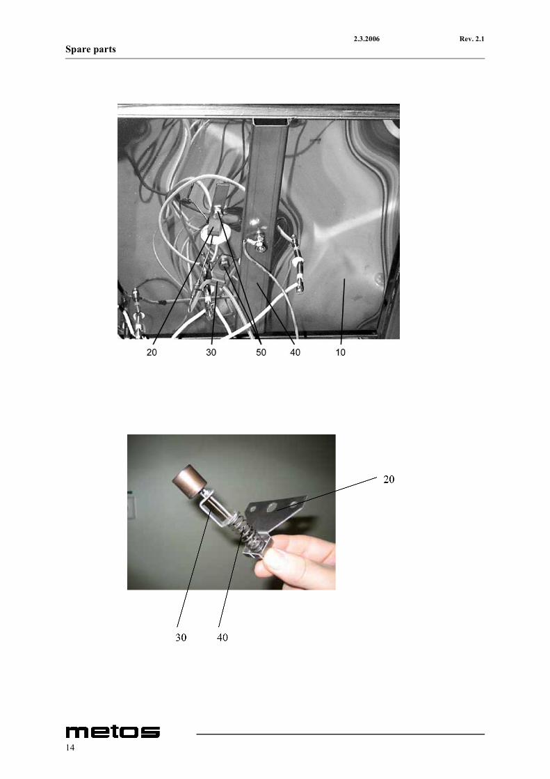
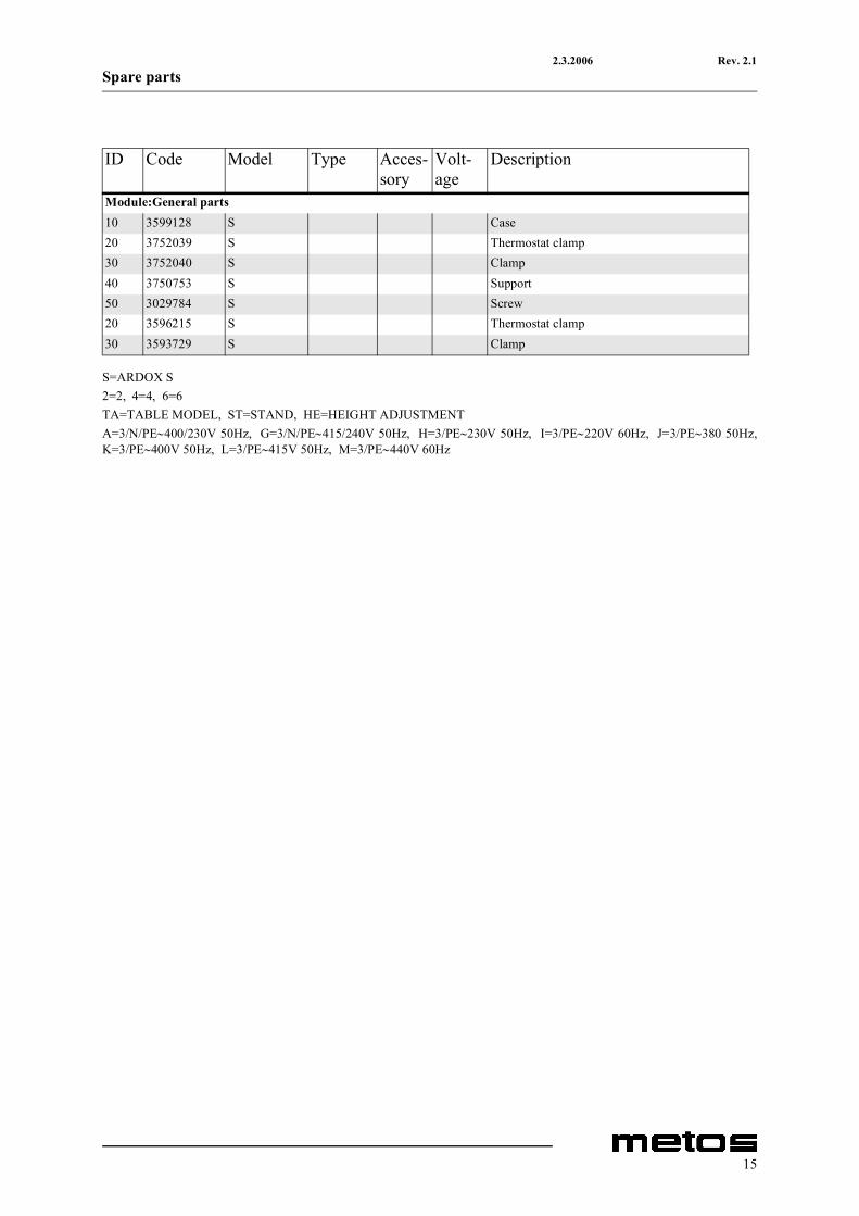
Module:General parts10 3599128 S Case20 3752039 S Thermostat clamp30 3752040 S Clamp40 3750753 S Support50 3029784 S Screw20 3596215 S Thermostat clamp30 3593729 S Clamp
15
2.3.2006 Rev. 2.1Spare parts
16
2.3.2006 Rev. 2.1Spare parts
S=ARDOX S2=2, 4=4, 6=6TA=TABLE MODEL, ST=STAND, HE=HEIGHT ADJUSTMENTA=3/N/PE∼400/230V 50Hz, G=3/N/PE∼415/240V 50Hz, H=3/PE∼230V 50Hz, I=3/PE∼220V 60Hz, J=3/PE∼380 50Hz,K=3/PE∼400V 50Hz, L=3/PE∼415V 50Hz, M=3/PE∼440V 60Hz
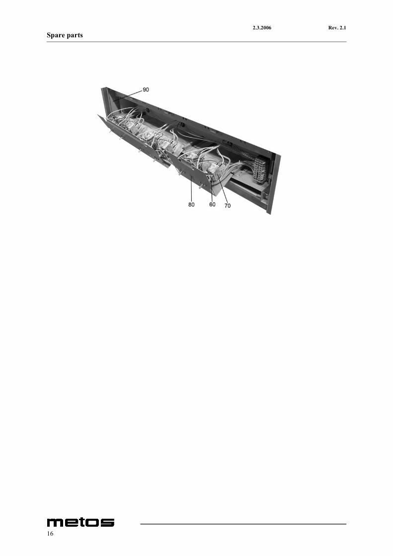
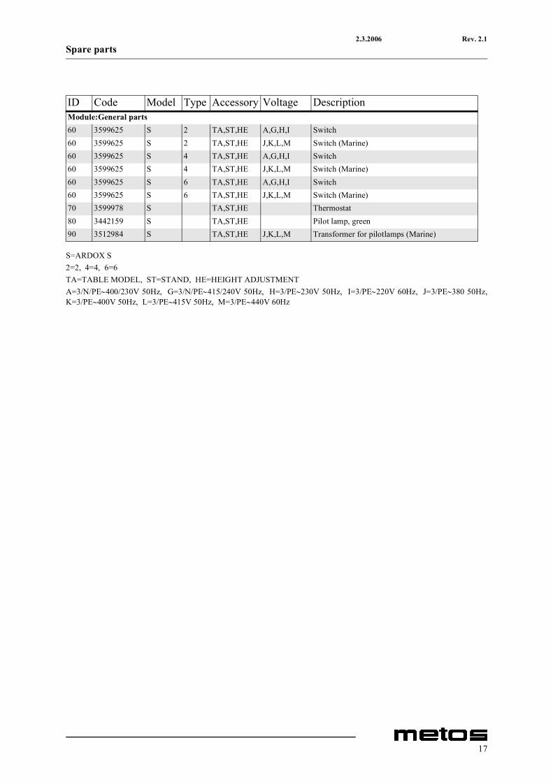
ID Code Model Type Accessory Voltage DescriptionModule:General parts60 3599625 S 2 TA,ST,HE A,G,H,I Switch60 3599625 S 2 TA,ST,HE J,K,L,M Switch (Marine)60 3599625 S 4 TA,ST,HE A,G,H,I Switch60 3599625 S 4 TA,ST,HE J,K,L,M Switch (Marine)60 3599625 S 6 TA,ST,HE A,G,H,I Switch60 3599625 S 6 TA,ST,HE J,K,L,M Switch (Marine)70 3599978 S TA,ST,HE Thermostat80 3442159 S TA,ST,HE Pilot lamp, green90 3512984 S TA,ST,HE J,K,L,M Transformer for pilotlamps (Marine)
17
2.3.2006 Rev. 2.1Spare parts
18
2.3.2006 Rev. 2.1Spare parts
S=ARDOX S2=2, 4=4, 6=6TA=TABLE MODEL, ST=STAND, HE=HEIGHT ADJUSTMENTA=3/N/PE∼400/230V 50Hz, G=3/N/PE∼415/240V 50Hz, H=3/PE∼230V 50Hz, I=3/PE∼220V 60Hz, J=3/PE∼380 50Hz,K=3/PE∼400V 50Hz, L=3/PE∼415V 50Hz, M=3/PE∼440V 60Hz
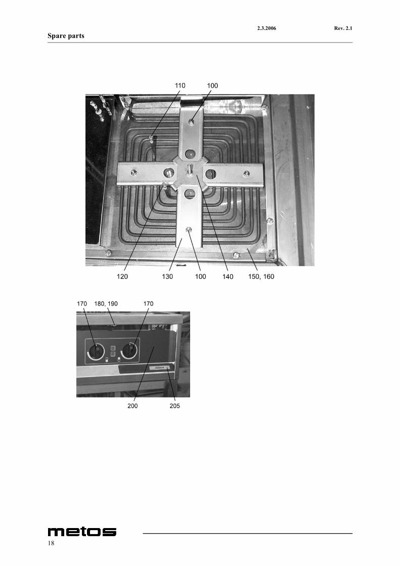
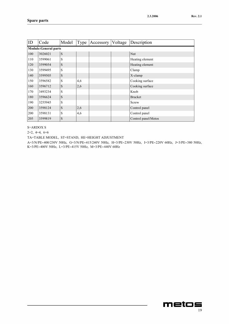
ID Code Model Type Accessory Voltage DescriptionModule:General parts100 3026021 S Nut110 3599061 S Heating element120 3599054 S Heating element130 3599495 S Clamp140 3599505 S X-clamp150 3596582 S 4,6 Cooking surface160 3596712 S 2,6 Cooking surface170 3493234 S Knob180 3596624 S Bracket190 3255945 S Screw200 3598124 S 2,6 Control panel200 3598131 S 4,6 Control panel205 3599819 S Control panel/Metos
19
2.3.2006 Rev. 2.1Spare parts
20
2.3.2006 Rev. 2.1Spare parts
S=ARDOX S2=2, 4=4, 6=6TA=TABLE MODEL, ST=STAND, HE=HEIGHT ADJUSTMENTA=3/N/PE∼400/230V 50Hz, G=3/N/PE∼415/240V 50Hz, H=3/PE∼230V 50Hz, I=3/PE∼220V 60Hz, J=3/PE∼380 50Hz,K=3/PE∼400V 50Hz, L=3/PE∼415V 50Hz, M=3/PE∼440V 60Hz
ID Code Model Type Acces-sory
Voltage Description
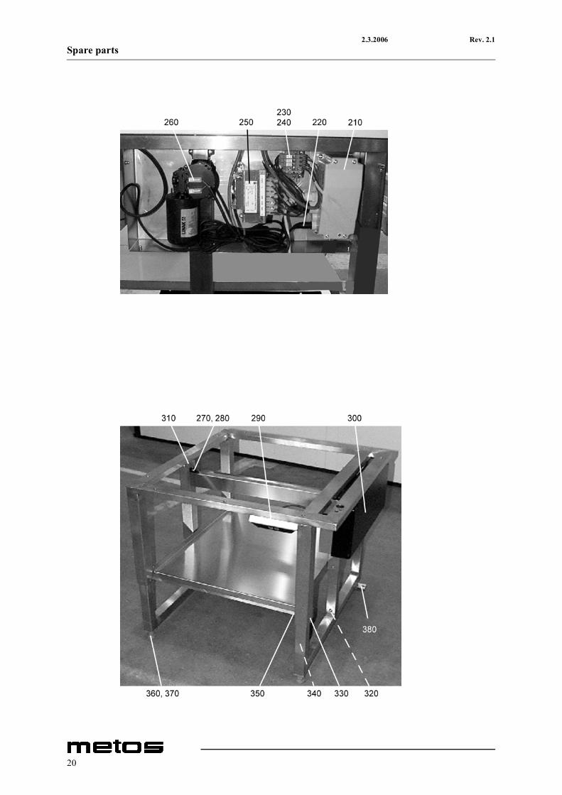
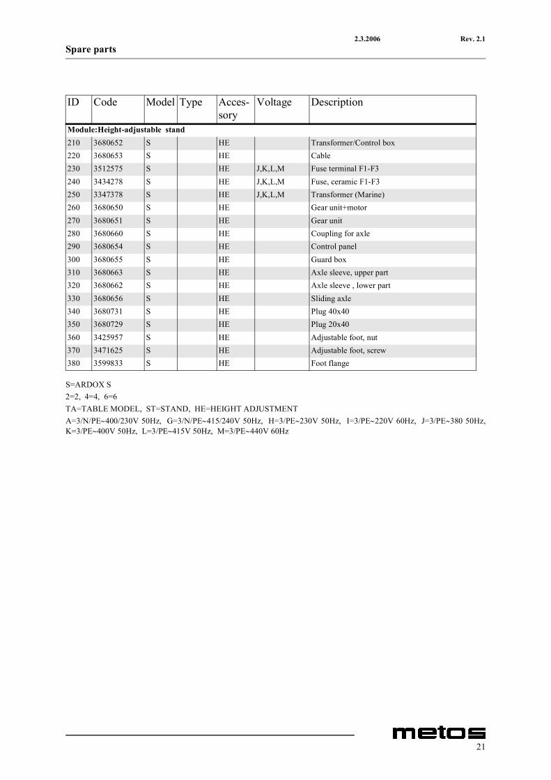
Module:Height-adjustable stand210 3680652 S HE Transformer/Control box220 3680653 S HE Cable230 3512575 S HE J,K,L,M Fuse terminal F1-F3240 3434278 S HE J,K,L,M Fuse, ceramic F1-F3250 3347378 S HE J,K,L,M Transformer (Marine)260 3680650 S HE Gear unit+motor270 3680651 S HE Gear unit280 3680660 S HE Coupling for axle290 3680654 S HE Control panel300 3680655 S HE Guard box310 3680663 S HE Axle sleeve, upper part320 3680662 S HE Axle sleeve , lower part330 3680656 S HE Sliding axle340 3680731 S HE Plug 40x40350 3680729 S HE Plug 20x40360 3425957 S HE Adjustable foot, nut370 3471625 S HE Adjustable foot, screw380 3599833 S HE Foot flange
21

2.3.2006 Rev. 2.1Spare parts
22
2.3.2006 Rev. 2.1Technical specifications
8. Technical specifications
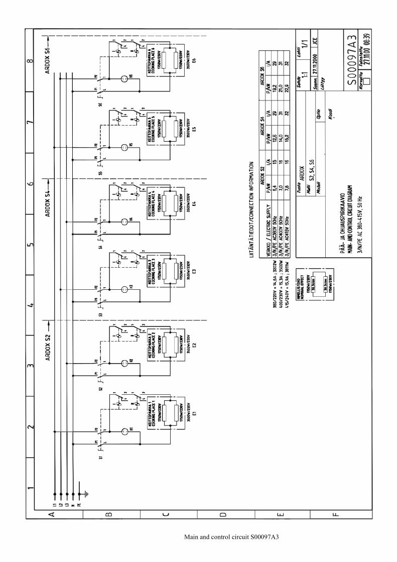
Main and control circuit S00097A3
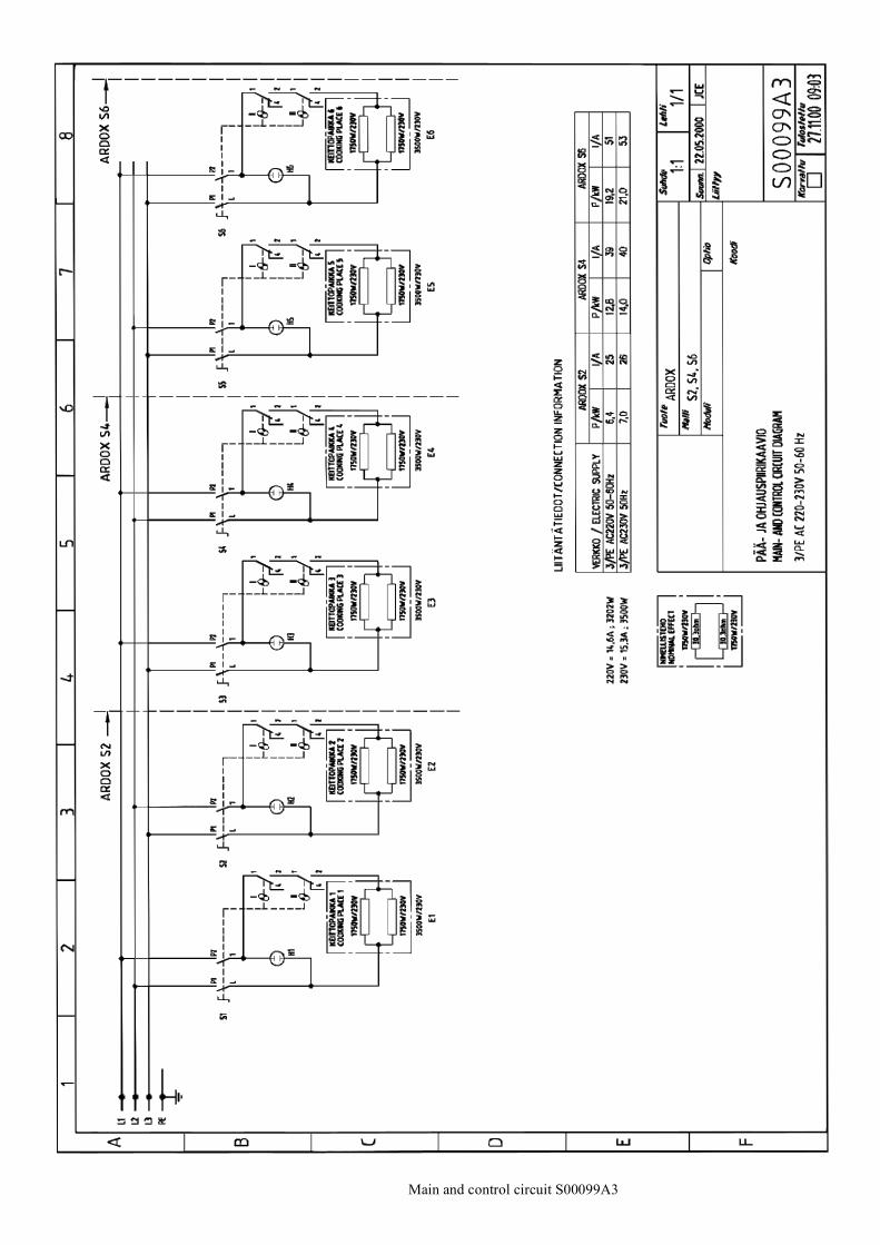
Main and control circuit S00099A3
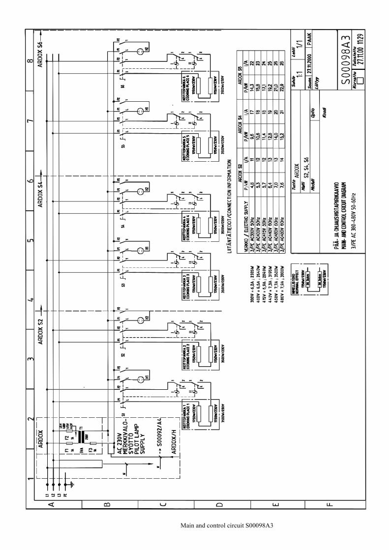
Main and control circuit S00098A3
Main and control circuit S00092A4
Installation drawing L00041B3
Installation drawing L00030B3
Installation drawing L00082A3
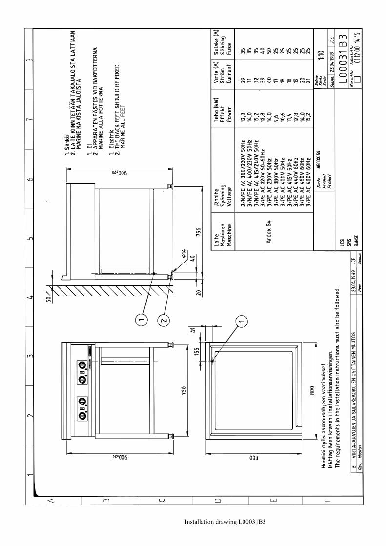
Installation drawing L00031B3
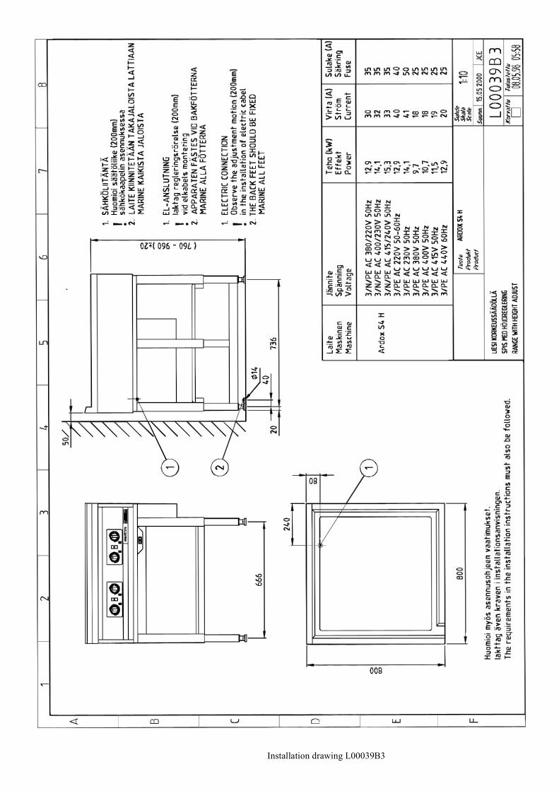
Installation drawing L00039B3
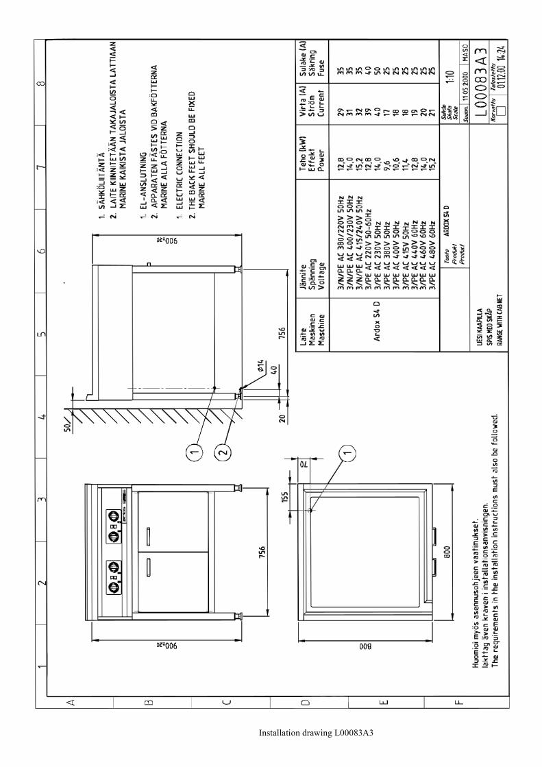
Installation drawing L00083A3
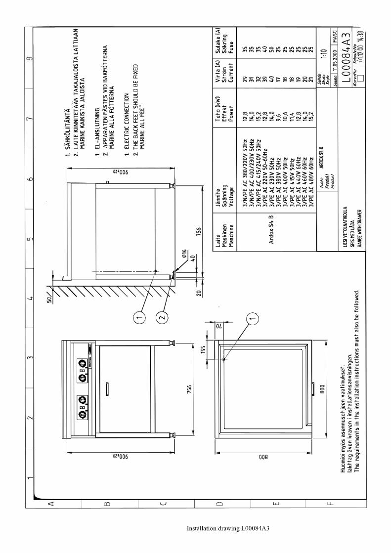
Installation drawing L00084A3
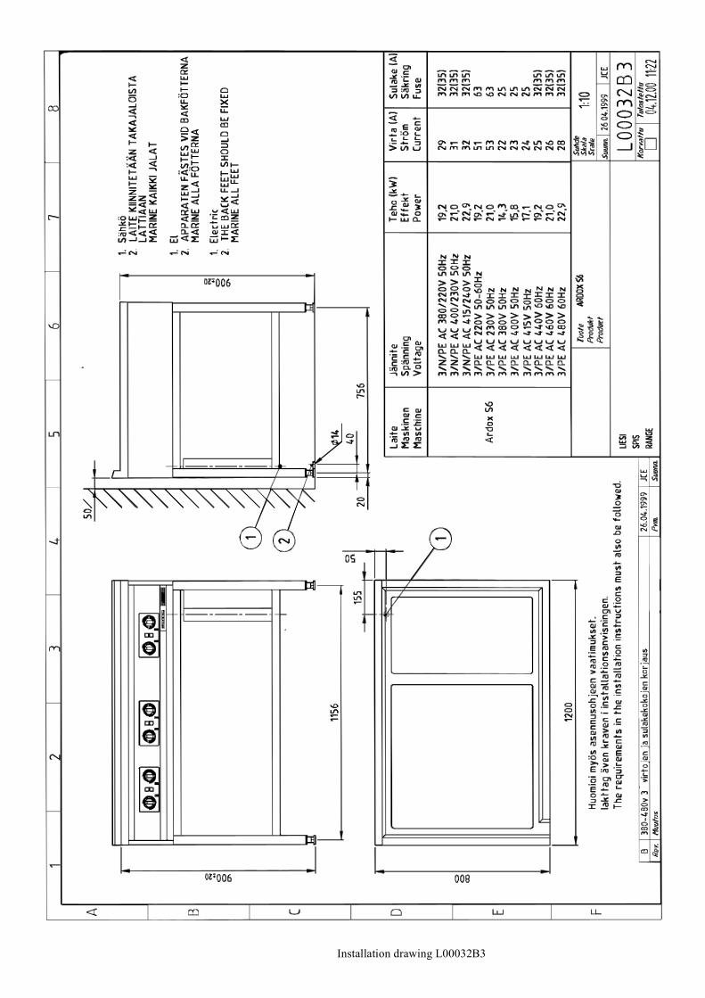
Installation drawing L00032B3
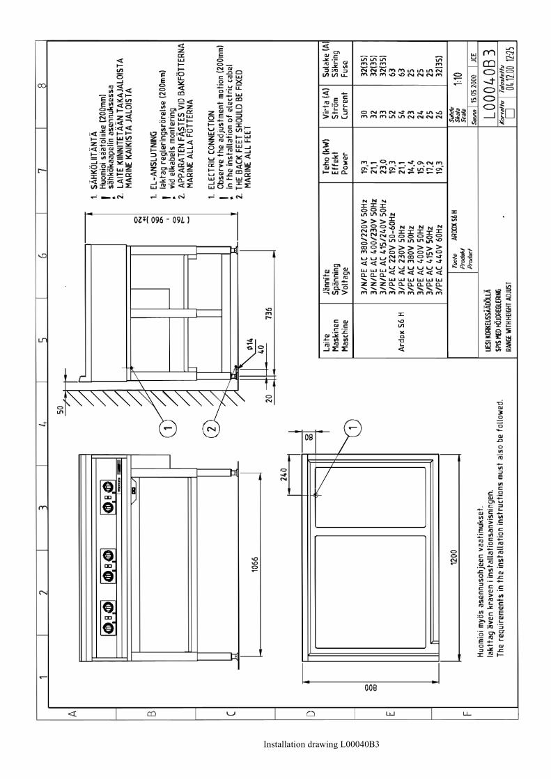
Installation drawing L00040B3
Installation drawing L00085A3
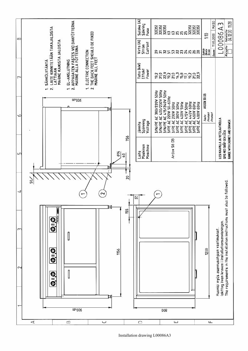
Installation drawing L00086A3
23
Main and control circuit S00097A3
Main and control circuit S00099A3
Main and control circuit S00098A3
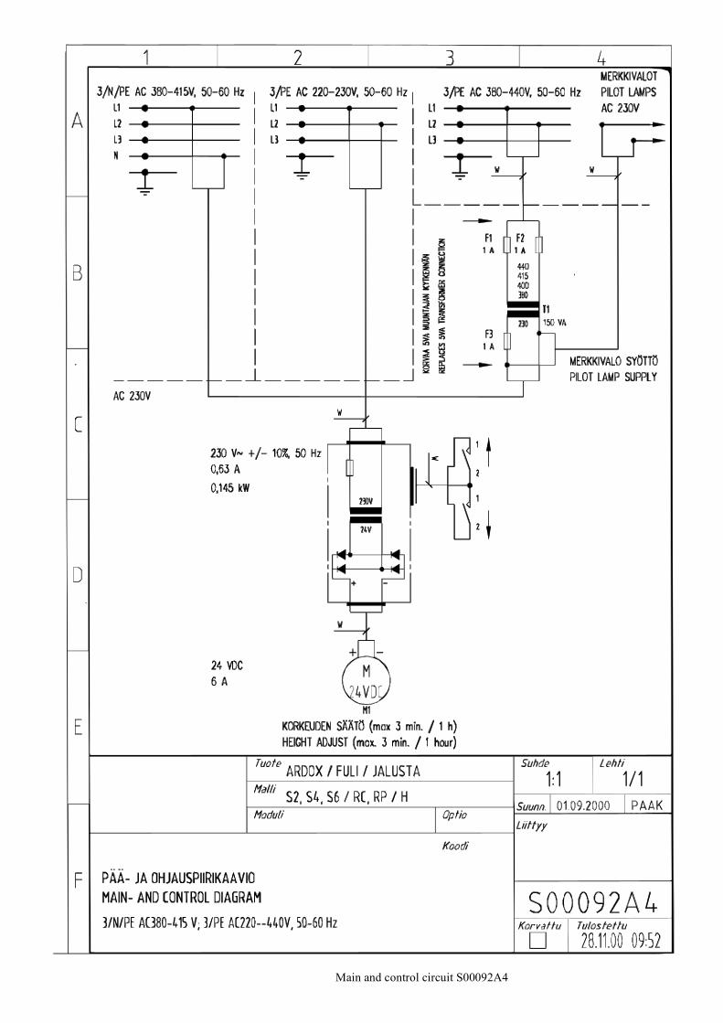
Main and control circuit S00092A4
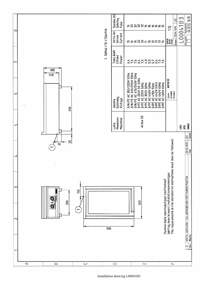
Installation drawing L00041B3
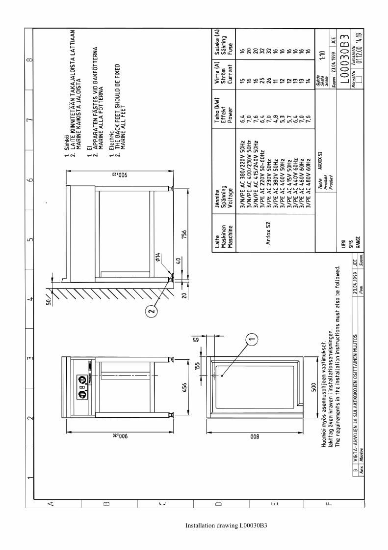
Installation drawing L00030B3
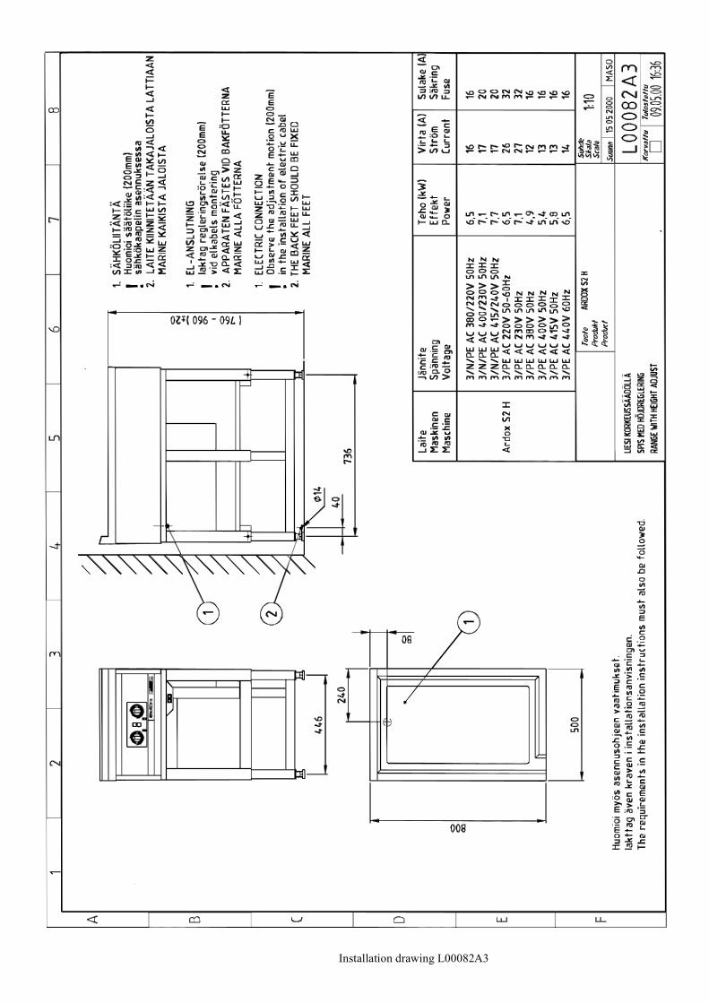
Installation drawing L00082A3
Installation drawing L00031B3
Installation drawing L00039B3
Installation drawing L00083A3
Installation drawing L00084A3
Installation drawing L00032B3
Installation drawing L00040B3

Installation drawing L00085A3
Installation drawing L00086A3
2.3.2006 Rev. 2.1Technical specifications
S=ARDOX S2=2, 4=4, 6=6TA=TABLE MODEL, ST=STAND, HE=HEIGHT ADJUSTMENTA=3/N/PE∼400/230V 50Hz, G=3/N/PE∼415/240V 50Hz, H=3/PE∼230V 50Hz, I=3/PE∼220V 60Hz, J=3/PE∼380 50Hz,K=3/PE∼400V 50Hz, L=3/PE∼415V 50Hz, M=3/PE∼440V 60Hz
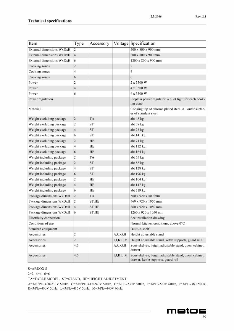
Item Type Accessory Voltage SpecificationExternal dimensions WxDxH 2 500 x 800 x 900 mmExternal dimensions WxDxH 4 800 x 800 x 900 mmExternal dimensions WxDxH 6 1200 x 800 x 900 mmCooking zones 2 2Cooking zones 4 4Cooking zones 6 6Power 2 2 x 3500 WPower 4 4 x 3500 WPower 6 6 x 3500 WPower regulation Stepless power regulator, a pilot light for each cook-
ing zoneMaterial Cooking top of chrome plated steel. All outer surfac-
es of stainless steel.Weight excluding package 2 TA abt 48 kgWeight excluding package 2 ST abt 58 kgWeight excluding package 4 ST abt 93 kgWeight excluding package 6 ST abt 141 kgWeight excluding package 2 HE abt 74 kgWeight excluding package 4 HE abt 112 kgWeight excluding package 6 HE abt 164 kgWeight including package 2 TA abt 65 kgWeight including package 2 ST abt 88 kgWeight including package 4 ST abt 128 kgWeight including package 6 ST abt 196 kgWeight including package 2 HE abt 104 kgWeight including package 4 HE abt 147 kgWeight including package 6 HE abt 219 kgPackage dimensions WxDxH 2 TA 560 x 920 x 400 mmPackage dimensions WxDxH 2 ST,HE 560 x 920 x 1050 mmPackage dimensions WxDxH 4 ST,HE 860 x 920 x 1050 mmPackage dimensions WxDxH 6 ST,HE 1260 x 920 x 1050 mmElectricity connection See installation drawingConditions of use Normal kitchen conditions, above 0°CStandard equipment Built-in shelfAccessories 2 A,C,G,H Height adjustable standAccessories 2 I,J,K,L,M Height adjustable stand, kettle supports, guard railAccessories 4,6 A,C,G,H Sous-shelves, height adjustable stand, oven, cabinet,
drawerAccessories 4,6 I,J,K,L,M Sous-shelves, height adjustable stand, oven, cabinet,
drawer, kettle supports, guard rail
39