Embed Size (px)
Citation preview
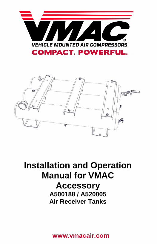
Installation and Operation Manual for VMAC
Accessory A500188 / A520005 Air Receiver Tanks

VMAC – Vehicle Mounted Air Compressors VMAC Technical Support: 1-888-241-2289 VMAC Knowledge Base: www.kb.vmacair.com
1
Owner / Installation Manual for VMAC Accessory A500188 / A520005
Air Receiver Tanks
Safety .......................................................................................................3 Warranty ..................................................................................................4 General Information ................................................................................5 Illustrated Parts List ...............................................................................6 General Safety Precautions ...................................................................7 Maintenance and Repair Safety .............................................................8 Installation ...............................................................................................9 Operation and Maintenance ...................................................................16
VMAC – Vehicle Mounted Air Compressors VMAC Technical Support: 1-888-241-2289
VMAC Knowledge Base: www.kb.vmacair.com 2
Document: 1901061 Changes and Revisions
Additional Application Information • For use with VMAC G300003, G300002, and G300001 Gas Engine
Driven 30 CFM Air Compressors.
Registered Trademarks All trademarks mentioned in this manual are the property of their respective owners. VMAC’s use of manufacturers’ trademarks in this manual is for identification of the products only and does not imply any affiliation to, or endorsement of said companies.
Loctite®, Loctite® 242, and Loctite® 567 are registered trademarks of Henkel AG & Company KGaA.
Important Information The information in this manual is intended for certified VMAC installers who have been trained in installation procedures and/or for people with mechanical trade certification who have the tools and equipment to properly and safely perform the installation. Do not attempt this installation without the appropriate mechanical training, knowledge and experience.
Follow all safety precautions for mechanical work. Any fabrication for correct fit in modified vehicles must follow industry standard “best practices”.
Notice Copyright © 2017 VMAC Global Technology Inc. All Rights Reserved. These materials are provided by VMAC for informational purposes only, without representation or warranty of any kind, and VMAC shall not be liable for errors or omissions with respect to the materials. The only warranties for VMAC products and services are those set forth in the express warranty statements accompanying such products and services, if any, and nothing herein shall be construed as constituting an additional warranty. Printing or copying of any page in this document in whole or in part is only permitted for personal use. All other use, copying or reproduction in both print and electronic form of any part of this document without the written consent of VMAC is prohibited. The information contained herein may be changed without prior notice.
Printed in Canada
Revision Revision Details Revised
by
Checked by
Implemented Eng. Tech. Qual.
Mech. Elec.
A Initial Release MSP JKR N/A GB AWG 8 Sept 2017
B ECN:17-159 Safety relief valve change MSP JKR N/A GB AWG 10 Nov 2017
VMAC – Vehicle Mounted Air Compressors VMAC Technical Support: 1-888-241-2289 VMAC Knowledge Base: www.kb.vmacair.com
3
Safety
Important Safety Notice The information contained in this manual is based on sound engineering principles, research, extensive field experience and technical information. Information is constantly changing with the addition of new models, assemblies, service techniques and running OEM changes. If a discrepancy is found in this manual, contact VMAC prior to initiating or proceeding with installation, service or repair. Current information may clarify the issue. Any person with knowledge of such discrepancies, who proceeds to perform service and repair assumes all risks.
Only proven service procedures are recommended. Anyone who departs from the specific instructions provided in this manual must first assure that their safety and that of others is not being compromised and that there will be no adverse effects on the operational safety or performance of the equipment.
VMAC will not be held responsible for any liability, consequential damages, injuries, loss or damage to individuals or to equipment as a result of the failure of any person to properly adhere to the procedures set out in this manual or standard safety practices. Safety should be the first consideration when performing any service operations. If there are any questions concerning the procedures in this manual or more information is required, please contact VMAC before beginning repairs.
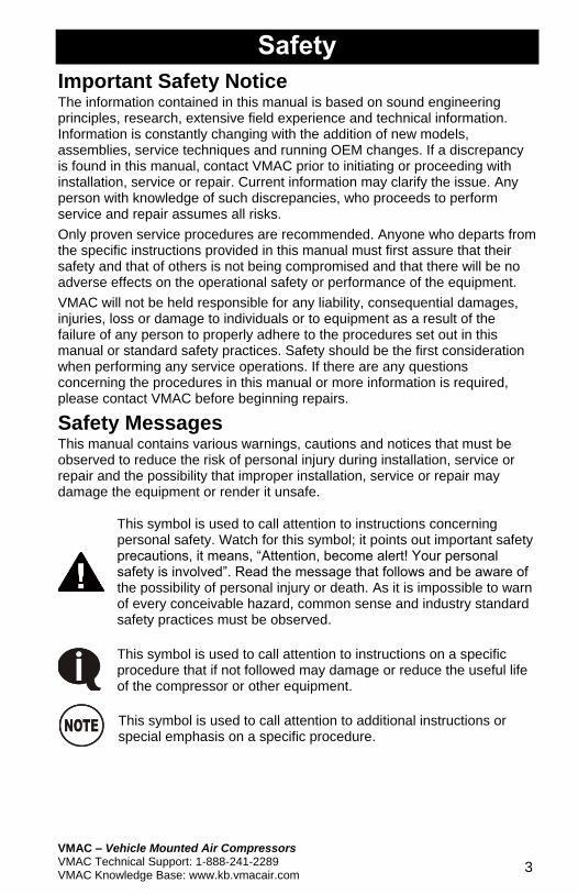
Safety Messages This manual contains various warnings, cautions and notices that must be observed to reduce the risk of personal injury during installation, service or repair and the possibility that improper installation, service or repair may damage the equipment or render it unsafe.
This symbol is used to call attention to instructions concerning personal safety. Watch for this symbol; it points out important safety precautions, it means, “Attention, become alert! Your personal safety is involved”. Read the message that follows and be aware of the possibility of personal injury or death. As it is impossible to warn of every conceivable hazard, common sense and industry standard safety practices must be observed.
This symbol is used to call attention to instructions on a specific procedure that if not followed may damage or reduce the useful life of the compressor or other equipment.
This symbol is used to call attention to additional instructions or special emphasis on a specific procedure.
VMAC – Vehicle Mounted Air Compressors VMAC Technical Support: 1-888-241-2289
VMAC Knowledge Base: www.kb.vmacair.com 4
Warranty
VMAC Standard Warranty (Limited) For complete warranty information, including both VMAC Standard Warranty (Limited) and VMAC Lifetime Warranty (Limited) requirements, please refer to our current published warranty located at:
www.vmacair.com/warranty If you do not have access to a computer, please contact us and we will be happy to send you our warranty.
VMAC’s warranty is subject to change without notice.
VMAC Lifetime Warranty (Limited) A VMAC Lifetime Limited Warranty is
offered on the base air compressor
only and only on UNDERHOOD,
Hydraulic Driven, Transmission
Mounted, Gas and Diesel Engine
Driven Air Compressors,
Multifunction Power Systems, and
other products as defined by VMAC,
provided that (i) the purchaser fully
completes and submits a warranty registration form within 3 months of
purchase, or 200 hours of operation, whichever occurs first; (ii) services are
completed in accordance with the Owner’s Manual; (iii) proof of purchase of
applicable service kits are made available to VMAC upon request.
The VMAC Lifetime Warranty is applicable to new products shipped on or after 1 October, 2015.
Warranty Registration The VMAC warranty registration form is located near the back of this manual. This warranty registration form must be completed and sent to VMAC at the time of installation for any subsequent warranty claim to be considered valid.
There are 4 ways the warranty can be registered with VMAC:
Online www.vmacair.com/warranty
Email [email protected]
Fax (250) 740-3201
Mail VMAC - Vehicle Mounted Air Compressors 1333 Kipp Road, Nanaimo, BC, Canada V9X 1R3
VMAC – Vehicle Mounted Air Compressors VMAC Technical Support: 1-888-241-2289 VMAC Knowledge Base: www.kb.vmacair.com
5
General Information
Before Starting Read this manual prior to installing or operating the Air Receiver Tank
package to ensure familiarity with the components, installation requirements
and how to operate the unit.
Open the package, unpack the components and identify them using the
included IPL on page 6.
Ordering Parts To order parts, contact a VMAC dealer. The dealer will ask for the VMAC serial number, part number, description and quantity. Locate the nearest dealer online at www.vmacair.com/dealer-locator or call 1-877-912-6605.
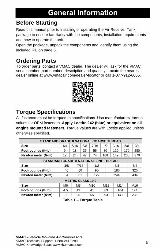
Torque Specifications All fasteners must be torqued to specifications. Use manufacturers’ torque
values for OEM fasteners. Apply Loctite 242 (blue) or equivalent on all
engine mounted fasteners. Torque values are with Loctite applied unless
otherwise specified.
STANDARD GRADE 8 NATIONAL COARSE THREAD
Size 1/4 5/16 3/8 7/16 1/2 9/16 5/8 3/4
Foot-pounds (ft•lb) 9 18 35 55 80 110 170 280
Newton meter (N•m) 12 24 47 74 108 149 230 379
STANDARD GRADE 8 NATIONAL FINE THREAD
Size 3/8 7/16 1/2 5/8 3/4
Foot-pounds (ft•lb) 40 60 90 180 320
Newton meter (N•m) 54 81 122 244 434
METRIC CLASS 10.9
Size M6 M8 M10 M12 M14 M16
Foot-pounds (ft•lb) 4.5 19 41 69 104 174
Newton meter (N•m) 6 25 55 93 141 236
Table 1 – Torque Table
VMAC – Vehicle Mounted Air Compressors VMAC Technical Support: 1-888-241-2289
VMAC Knowledge Base: www.kb.vmacair.com
6
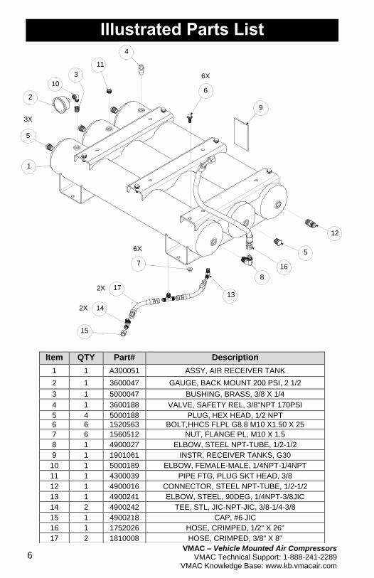
Illustrated Parts List
Item QTY Part# Description
1 1 A300051 ASSY, AIR RECEIVER TANK
2 1 3600047 GAUGE, BACK MOUNT 200 PSI, 2 1/2
3 1 5000047 BUSHING, BRASS, 3/8 X 1/4
4 1 3600188 VALVE, SAFETY REL, 3/8"NPT 170PSI
5 4 5000188 PLUG, HEX HEAD, 1/2 NPT
6 6 1520563 BOLT,HHCS FLPL G8.8 M10 X1.50 X 25
7 6 1560512 NUT, FLANGE PL, M10 X 1.5
8 1 4900027 ELBOW, STEEL NPT-TUBE, 1/2-1/2
9 1 1901061 INSTR, RECEIVER TANKS, G30
10 1 5000189 ELBOW, FEMALE-MALE, 1/4NPT-1/4NPT
11 1 4300039 PIPE FTG, PLUG SKT HEAD, 3/8
12 1 4900016 CONNECTOR, STEEL NPT-TUBE, 1/2-1/2
13 1 4900241 ELBOW, STEEL, 90DEG, 1/4NPT-3/8JIC
14 2 4900242 TEE, STL, JIC-NPT-JIC, 3/8-1/4-3/8
15 1 4900218 CAP, #6 JIC
16 1 1752026 HOSE, CRIMPED, 1/2" X 26"
17 2 1810008 HOSE, CRIMPED, 3/8" X 8"
10
11
4
3
1
6
6X
9
8
5
12
7
6X
13172X
142X
15
16
5
3X
VMAC – Vehicle Mounted Air Compressors VMAC Technical Support: 1-888-241-2289 VMAC Knowledge Base: www.kb.vmacair.com
7
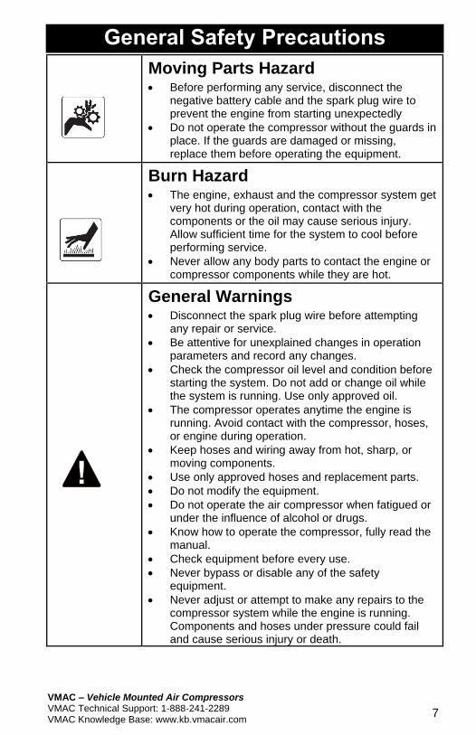
General Safety Precautions
Moving Parts Hazard • Before performing any service, disconnect the
negative battery cable and the spark plug wire to prevent the engine from starting unexpectedly
• Do not operate the compressor without the guards in place. If the guards are damaged or missing, replace them before operating the equipment.
Burn Hazard • The engine, exhaust and the compressor system get
very hot during operation, contact with the components or the oil may cause serious injury. Allow sufficient time for the system to cool before performing service.
• Never allow any body parts to contact the engine or compressor components while they are hot.
General Warnings • Disconnect the spark plug wire before attempting
any repair or service.
• Be attentive for unexplained changes in operation parameters and record any changes.
• Check the compressor oil level and condition before starting the system. Do not add or change oil while the system is running. Use only approved oil.
• The compressor operates anytime the engine is running. Avoid contact with the compressor, hoses, or engine during operation.
• Keep hoses and wiring away from hot, sharp, or moving components.
• Use only approved hoses and replacement parts.
• Do not modify the equipment.
• Do not operate the air compressor when fatigued or under the influence of alcohol or drugs.
• Know how to operate the compressor, fully read the manual.
• Check equipment before every use.
• Never bypass or disable any of the safety equipment.
• Never adjust or attempt to make any repairs to the compressor system while the engine is running. Components and hoses under pressure could fail and cause serious injury or death.
VMAC – Vehicle Mounted Air Compressors VMAC Technical Support: 1-888-241-2289
VMAC Knowledge Base: www.kb.vmacair.com
8
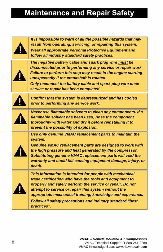
Maintenance and Repair Safety
It is impossible to warn of all the possible hazards that may
result from operating, servicing, or repairing this system.
Wear all appropriate Personal Protective Equipment and
follow all industry standard safety practices.
Confirm that the system is depressurized and has cooled
prior to performing any service work.
Never use flammable solvents to clean any components. If a
flammable solvent has been used, rinse the component
thoroughly with water and dry it before reinstalling it to
prevent the possibility of explosion.
Use only genuine VMAC replacement parts to maintain the
system.
Genuine VMAC replacement parts are designed to work with
the high pressure and heat generated by the compressor.
Substituting genuine VMAC replacement parts will void the
warranty and could fail causing equipment damage, injury, or
death.
This information is intended for people with mechanical
trade certification who have the tools and equipment to
properly and safely perform the service or repair. Do not
attempt to service or repair this system without the
appropriate mechanical training, knowledge and experience.
Follow all safety precautions and industry standard “best
practices”.
The negative battery cable and spark plug wire must be
disconnected prior to performing any service or repair work.
Failure to perform this step may result in the engine starting
unexpectedly if the crankshaft is rotated.
Only reconnect the battery cable and spark plug wire once
service or repair has been completed.
VMAC – Vehicle Mounted Air Compressors VMAC Technical Support: 1-888-241-2289 VMAC Knowledge Base: www.kb.vmacair.com
9
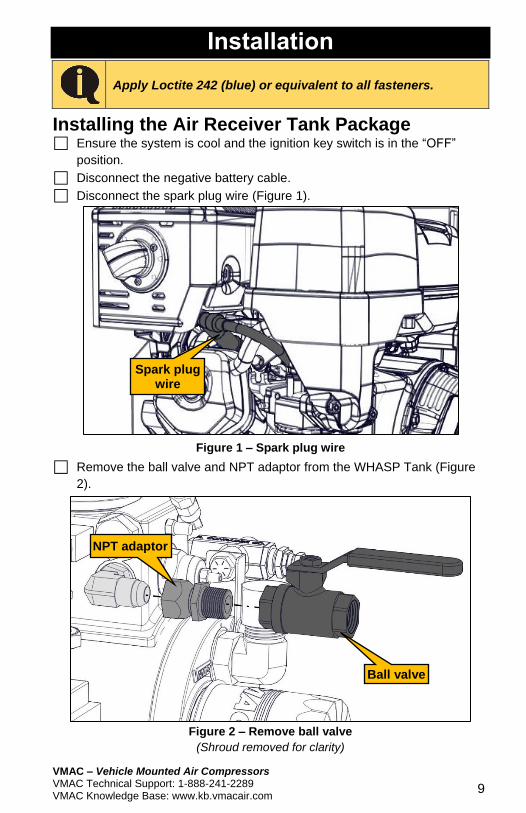
Installation
Apply Loctite 242 (blue) or equivalent to all fasteners.
Installing the Air Receiver Tank Package Ensure the system is cool and the ignition key switch is in the “OFF”
position.
Disconnect the negative battery cable.
Disconnect the spark plug wire (Figure 1).
Figure 1 – Spark plug wire
Remove the ball valve and NPT adaptor from the WHASP Tank (Figure
2).
Figure 2 – Remove ball valve
(Shroud removed for clarity)
NPT adaptor
Ball valve
Spark plug wire
VMAC – Vehicle Mounted Air Compressors VMAC Technical Support: 1-888-241-2289
VMAC Knowledge Base: www.kb.vmacair.com
10
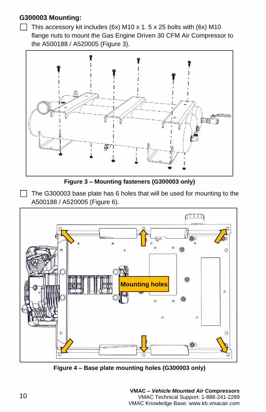
G300003 Mounting:
This accessory kit includes (6x) M10 x 1. 5 x 25 bolts with (6x) M10
flange nuts to mount the Gas Engine Driven 30 CFM Air Compressor to
the A500188 / A520005 (Figure 3).
Figure 3 – Mounting fasteners (G300003 only)
The G300003 base plate has 6 holes that will be used for mounting to the
A500188 / A520005 (Figure 6).
Figure 4 – Base plate mounting holes (G300003 only)
Mounting holes
VMAC – Vehicle Mounted Air Compressors VMAC Technical Support: 1-888-241-2289 VMAC Knowledge Base: www.kb.vmacair.com
11
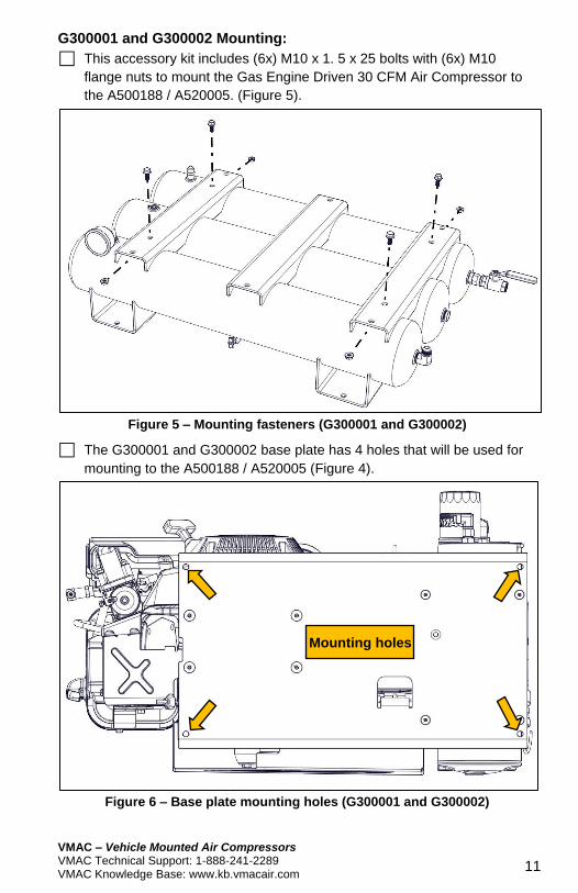
G300001 and G300002 Mounting:
This accessory kit includes (6x) M10 x 1. 5 x 25 bolts with (6x) M10
flange nuts to mount the Gas Engine Driven 30 CFM Air Compressor to
the A500188 / A520005. (Figure 5).
Figure 5 – Mounting fasteners (G300001 and G300002)
The G300001 and G300002 base plate has 4 holes that will be used for
mounting to the A500188 / A520005 (Figure 4).
Figure 6 – Base plate mounting holes (G300001 and G300002)
Mounting holes
VMAC – Vehicle Mounted Air Compressors VMAC Technical Support: 1-888-241-2289
VMAC Knowledge Base: www.kb.vmacair.com
12
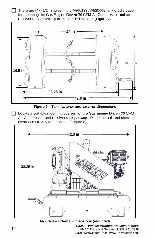
There are (4x) 1/2 in holes in the A500188 / A520005 tank cradle base for mounting the Gas Engine Driven 30 CFM Air Compressor and air receiver tank assembly in its intended location (Figure 7).
Figure 7 – Tank fastener and external dimensions
Locate a suitable mounting position for the Gas Engine Driven 30 CFM Air Compressor and receiver tank package. Place the unit and check clearances to any other objects (Figure 8).
Figure 8 – External dimensions (mounted)
42.0 in
32.25 in
24 in
19.5 in
20.5 in
35.25 in
42.0 in
VMAC – Vehicle Mounted Air Compressors VMAC Technical Support: 1-888-241-2289 VMAC Knowledge Base: www.kb.vmacair.com
13
Drill (4x) 1/2 in holes in the surface that the unit will be mounted to and
secure the A500188 / A520005 using (4x) 3/8 in bolts, washers, and
locknuts (or Loctite 242). Fasteners for mounting the A500188 / A520005
are not supplied (Figure 7).
The Gas Engine Driven 30 CFM Air Compressor is heavy,
take all precautions when lifting to prevent injury.
The powder coated mating surfaces of the air receiver tank
and Gas Engine Driven 30 CFM Air Compressor are very
slippery. VMAC suggests keeping the Gas Driven 30 CFM Air
Compressor safely supported until all of the fasteners are
installed.
Mount the Gas Engine Driven 30 CFM Air Compressor on top of the air
receiver tank package.
Apply Loctite 242 (blue) to the 6 supplied M10 x 1.5 x 25 mounting bolts
and secure the Gas Engine Driven 30 CFM Air Compressor to the air
receiver tank package.
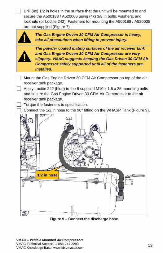
Torque the fasteners to specification.
Connect the 1/2 in hose to the 90° fitting on the WHASP Tank (Figure 9).
Figure 9 – Connect the discharge hose
1/2 in hose
VMAC – Vehicle Mounted Air Compressors VMAC Technical Support: 1-888-241-2289
VMAC Knowledge Base: www.kb.vmacair.com
14
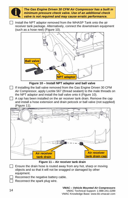
The Gas Engine Driven 30 CFM Air Compressor has a built in minimum pressure check valve. Use of an additional check valve is not required and may cause erratic performance.
Install the NPT adaptor removed from the WHASP Tank onto the air receiver tank package. Alternatively, connect the downstream equipment (such as a hose reel) (Figure 10).
Figure 10 – Install NPT adaptor and ball valve
If installing the ball valve removed from the Gas Engine Driven 30 CFM Air Compressor, apply Loctite 567 (thread sealant) to the male threads on the NPT adaptor and install the ball valve onto it (Figure 10).
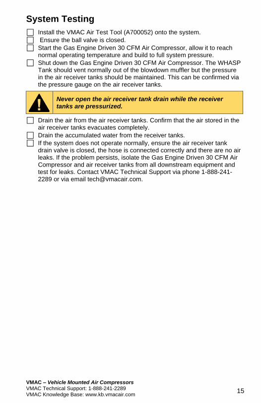
A cap has been installed on the air receiver tank drain. Remove the cap and install a hose extension and drain petcock or ball valve (not supplied) (Figure 11).
Figure 11 – Air receiver tank drain
Ensure the drain hose is routed away from any hot, sharp or moving objects and so that it will not be snagged or damaged by other equipment.
Reconnect the negative battery cable.
Reconnect the spark plug wire.
Ball valve
NPT adaptor
Air receiver tank drain
Air receiver tank drain cap
VMAC – Vehicle Mounted Air Compressors VMAC Technical Support: 1-888-241-2289 VMAC Knowledge Base: www.kb.vmacair.com
15
System Testing
Install the VMAC Air Test Tool (A700052) onto the system.
Ensure the ball valve is closed.
Start the Gas Engine Driven 30 CFM Air Compressor, allow it to reach normal operating temperature and build to full system pressure.
Shut down the Gas Engine Driven 30 CFM Air Compressor. The WHASP Tank should vent normally out of the blowdown muffler but the pressure in the air receiver tanks should be maintained. This can be confirmed via the pressure gauge on the air receiver tanks.
Never open the air receiver tank drain while the receiver tanks are pressurized.
Drain the air from the air receiver tanks. Confirm that the air stored in the air receiver tanks evacuates completely.
Drain the accumulated water from the receiver tanks.
If the system does not operate normally, ensure the air receiver tank drain valve is closed, the hose is connected correctly and there are no air leaks. If the problem persists, isolate the Gas Engine Driven 30 CFM Air Compressor and air receiver tanks from all downstream equipment and test for leaks. Contact VMAC Technical Support via phone 1-888-241-2289 or via email [email protected].
VMAC – Vehicle Mounted Air Compressors VMAC Technical Support: 1-888-241-2289
VMAC Knowledge Base: www.kb.vmacair.com
16
Operation and Maintenance
The air receiver tanks should be drained a minimum of once
per day to evacuate the moisture from the tank. This will help
to prevent corrosion from forming in the tanks.
Do not start the Gas Engine Driven 30 CFM Air Compressor
with the ball valve wide open and with no tool attached as
this will cause compressor oil to carry over into the
airstream.
When compressed air is no longer needed, shut down the Gas Engine
Driven 30 CFM Air Compressor as normal.
Open the ball valve on the receiver tank package (or connect a tool to the
system) to evacuate the stored air.
Never open the air receiver tank drain while the receiver tanks are pressurized.
Once the air has been evacuated from the receiver tanks, open the drain
on the receiver tank.
Once all of the water has drained, close the receiver tank drain.