Embed Size (px)
Citation preview
This is the safety alert symbol. It is used to alert you to potential personal injury hazards. Obey all safety messages that follow this symbol to avoid possible injury or death.
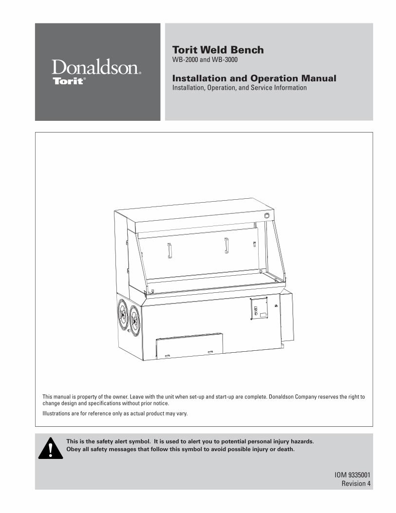
This manual is property of the owner. Leave with the unit when set-up and start-up are complete. Donaldson Company reserves the right to change design and specifications without prior notice.
Illustrations are for reference only as actual product may vary.
Torit Weld BenchWB-2000 and WB-3000
Installation and Operation ManualInstallation, Operation, and Service Information
IOM 9335001Revision 4
APPLICATION OF DUST CONTROL EQUIPMENT
Combustible materials such as buffing lint, paper, wood, metal dusts, weld fume, or flammable coolants or solvents represent potential fire and/or explosion hazards. Use special care when selecting, installing, and operating all dust, fume, or mist collection equipment when such combustible materials may be present in order to protect workers and property from serious injury or damage due to a fire and/or explosion.
Consult and comply with all National and Local Codes related to fire and/or explosion properties of combustible materials when determining the location and operation of all dust, fume, or mist collection equipment.
When combustible materials are present you must consult with an expert in fire extinguishing and/or explosion protection systems, who is also familiar with the local codes, for support and guidance on the selection and installation of an appropriate fire and/or explosion protection system.
DO NOT allow sparks, cigarettes or other burning objects to enter the hood or duct of any dust, fume, or mist collection equipment as these may initiate a fire or explosion of any combustible materials accumulated in the collector.
Portions of dust, mist, and fume-collection equipment, including the clean- and dirty-air plenums may be considered “OSHA Confined Spaces.” Refer to the appropriate OSHA regulations to determine if a specific installation should be considered a confined space and if a permit program is required.
Recirculating filtered air in your facility can be a hazard. Consult with OSHA to ensure compliance with all codes regarding recirculating filtered air.
Improper operation of a dust, fume, or mist control system may contribute to conditions in the work area or facility that could result in severe personal injury and product or property damage. Check that all dust, fume, or mist collection equipment is properly selected, installed, and operated for its intended use.
This manual contains specific precautionary statements relative to worker safety. Read this manual thoroughly and comply as directed. Instruct all personnel on the safe use and maintenance procedures related to this equipment. Discuss any questions on the application, use, or maintenance of this equipment with a Donaldson Torit representative.
For optimum collector performance, use only Donaldson Torit replacement parts.
Donaldson Company, Inc.
Model Number _____________________________ Serial Number ______________________________
Ship Date _________________________________ Installation Date _____________________________
Customer Name _______________________________________________________________________
Address _____________________________________________________________________________
____________________________________________________________________________________
Filter Type ____________________________________________________________________________
Accessories __________________________________________________________________________
Other ________________________________________________________________________________
DANGER indicates a hazardous situation which, if not avoided, will result in death or serious injury.
WARNING indicates a hazardous situation which, if not avoided, could result in death or serious injury.
CAUTION, used with the safety alert symbol, indicates a hazardous situation which, if not avoided, could result in minor or moderate injury.
NOTICE is used to address practices not related to personal injury that may result in damage to equipment.
NOTICE
Torit Weld Bench, WB-2000 and WB-3000
3
Data Sheet
Contents
Description ................................................................................4Purpose and Intended Use .....................................................4Rating and Specification Information ...................................5Operation ...................................................................................6Inspection on Arrival ...............................................................7Installation Codes and Procedures ......................................7Installation.................................................................................7
Unit Location .........................................................................7Typical Installation ...................................................................8Rigging Instructions.................................................................9
Hoisting Information ............................................................9Standard Equipment ..............................................................10
Compressed Air Installation .............................................12
Solid-State Timer Installation...............................................13Solenoid Connection ..........................................................13Timer and Solenoid Specifications ..................................13Optional IEC Control Panel ................................................15
Preliminary Start-Up Check .................................................17Operating Adjustments ......................................................18
Maintenance Information .....................................................18Operational Checklist ........................................................18Filter Removal and Installation .........................................19Filter Cleaning .....................................................................20Dust Removal ......................................................................21
Split Taper™ Bushing Mounting Instructions ...................22Troubleshooting ......................................................................23Service Notes .........................................................................25
Combustible materials such as buffing lint, paper, wood, metal dusts, weld fume, or flammable coolants or solvents represent potential fire and/or explosion hazards. Use special care when
selecting, installing, and operating all dust, fume, or mist collection equipment when such combustible materials may be present in order to protect workers and property from serious injury or damage due to a fire and/or explosion.
Consult and comply with all National and Local Codes related to fire and/or explosion properties of combustible materials when determining the location and operation of all dust, fume, or mist collection equipment.
Standard Donaldson Torit equipment is not equipped with fire extinguishing or explosion protection systems.
4
Donaldson Company, Inc.
Description
The Torit Weld Bench is a source collector designed mainly for weld fume. Standard models are the 2000 cfm unit with two (2) filters and the 3000 cfm unit with four (4) filters. To ensure high efficiency operation, always use the Torit Ultra-Web® II FR (flame retardant) filter cartridge. These elements, which are an example of Donaldson Company’s state of the art filtration technology, help ensure that only clean air is returned to the plant environment. Technical and field support are always available from your local Torit representative and distributors.
Purpose and Intended Use
Misuse or modification of this equipment may result in personal
injury.
Do not misuse or modify.
Torit Weld Bench, WB-2000 and WB-3000
5
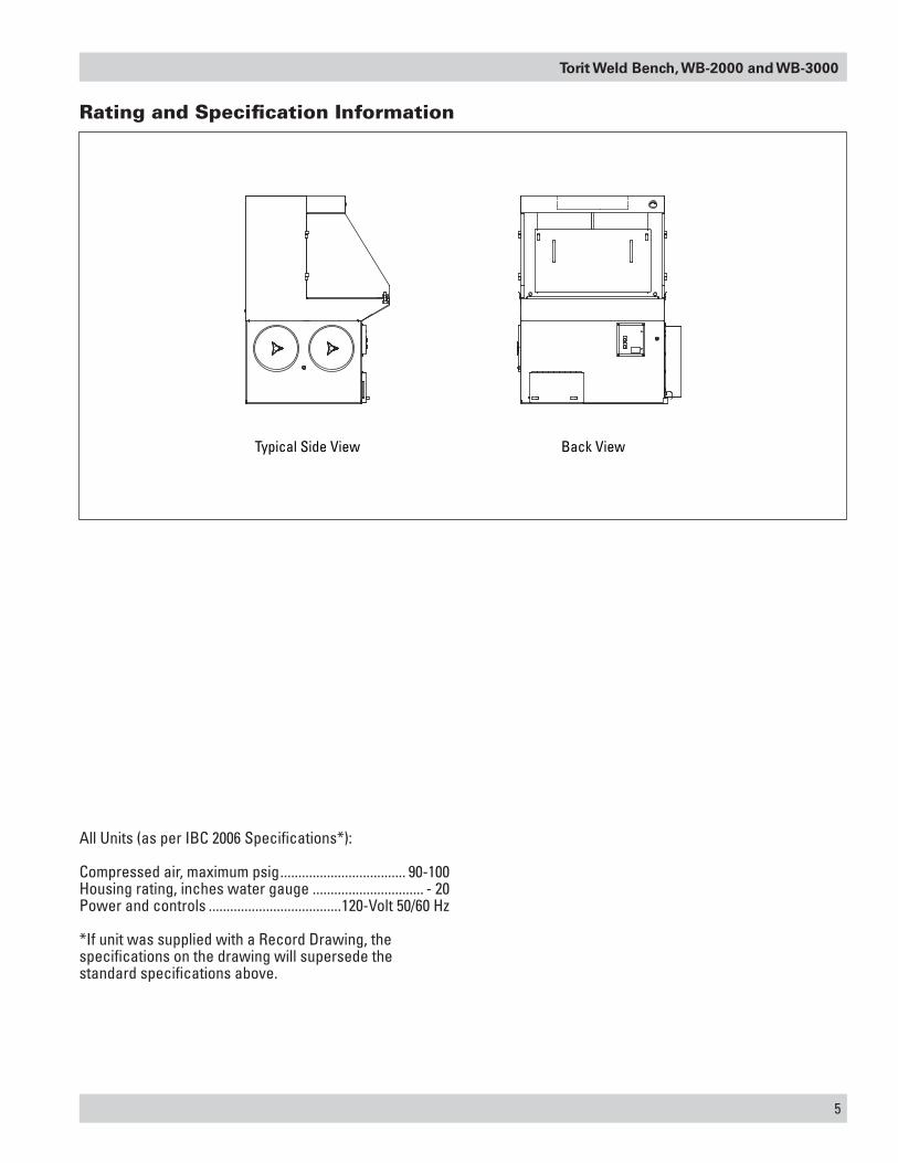
All Units (as per IBC 2006 Specifications*):
Compressed air, maximum psig ................................... 90-100Housing rating, inches water gauge ............................... - 20Power and controls .....................................120-Volt 50/60 Hz
*If unit was supplied with a Record Drawing, the specifications on the drawing will supersede the standard specifications above.
Rating and Specification Information
Typical Side View Back View
6
Donaldson Company, Inc.
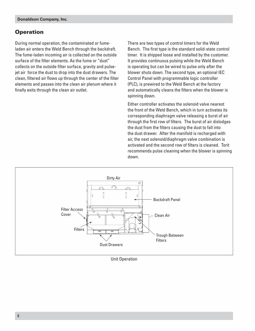
Operation
During normal operation, the contaminated or fume-laden air enters the Weld Bench through the backdraft. The fume-laden incoming air is collected on the outside surface of the filter elements. As the fume or “dust” collects on the outside filter surface, gravity and pulse-jet air force the dust to drop into the dust drawers. The clean, filtered air flows up through the center of the filter elements and passes into the clean air plenum where it finally exits through the clean air outlet.
There are two types of control timers for the Weld Bench. The first type is the standard solid-state control timer. It is shipped loose and installed by the customer. It provides continuous pulsing while the Weld Bench is operating but can be wired to pulse only after the blower shuts down. The second type, an optional IEC Control Panel with programmable logic controller (PLC), is prewired to the Weld Bench at the factory and automatically cleans the filters when the blower is spinning down.
Either controller activates the solenoid valve nearest the front of the Weld Bench, which in turn activates its corresponding diaphragm valve releasing a burst of air through the first row of filters. The burst of air dislodges the dust from the filters causing the dust to fall into the dust drawer. After the manifold is recharged with air, the next solenoid/diaphragm valve combination is activated and the second row of filters is cleaned. Torit recommends pulse cleaning when the blower is spinning down.
Unit Operation
Dirty Air
Backdraft Panel
Clean Air
Trough Between Filters
Dust Drawers
Filters
Filter AccessCover
Torit Weld Bench, WB-2000 and WB-3000
7
Inspection on Arrival
1. Inspect unit on delivery.
2. Report any damage to the delivery carrier.
3. Request a written inspection report from the Claims Inspector to substantiate any damage claim.
4. File claims with the delivery carrier.
5. Compare unit received with description of product ordered.
6. Report incomplete shipments to the delivery carrier and your Donaldson Torit representative.
7. Remove crates and shipping straps. Remove loose components and accessory packages before lifting unit from truck.
8. Check for hardware that may have loosened during shipping.
9. Use caution removing temporary covers.
Installation Codes and Procedures
Codes may regulate recirculating filtered air in your facility.
Consult with the appropriate authorities having jurisdiction to ensure compliance with all national and local codes regarding recirculating filtered air.
Safe and efficient operation of the unit depends on proper installation.
Authorities with jurisdiction should be consulted before installing to verify local codes and installation procedures. In the absence of such codes, install unit according to the National Electric Code, NFPA No. 70-latest edition and NFPA 91 (NFPA 654 if combustible dust is present).
A qualified installation and service agent must complete installation and service of this equipment.
All shipping materials, including shipping covers, must be removed from the unit prior to, or during unit installation.
Failure to remove shipping materials from the unit will
compromise unit performance.
Inspect unit to ensure all hardware is properly installed and tight prior to operating collector.
Installation
Site selection must account for wind, seismic zone, and
other live-load conditions when selecting the location for all units.
Codes may regulate acceptable locations for installing dust collectors. Consult with the appropriate authorities having jurisdiction to ensure compliance with all national and local codes regarding dust collector installation.
The welding work surface is seven gauge hot rolled steel. A waterborn corrosion resistant clear film has been applied by the factory to the work surface. This clear film must be removed before operating by washing the work surface with a detergent cleaner and then drying with a cloth.
Do not start welding without the removal of the corrosion
resistant film. Undesirable oil residue will be generated if the film is not removed prior to welding.
Unit Location
Donaldson Torit equipment is not designed to support site-installed
ducts, interconnecting piping, or electrical services. All ducts, piping, or electrical services supplied by others must be adequately supported to prevent severe personal injury and/or property damage.
When hazardous conditions or materials are present, consult with local authorities for the proper location of the collector.
Foundation must be capable of supporting the entire weight of the unit, plus the weight of the collected material, piping, and ductwork.
Prepare the foundation in the selected location. Install anchor bolts to extend a minimum of 1 3/4-inches above foundation.
Locate the collector to ensure easy access to electrical and compressed-air connections and routine maintenance.
NOTICE
NOTICE
8
Donaldson Company, Inc.
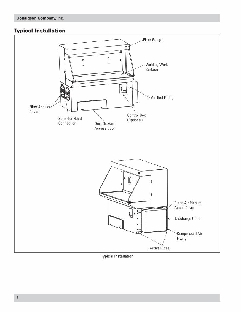
Filter AccessCovers
Sprinkler Head Connection Dust Drawer
Access Door
Control Box(Optional)
Clean Air Plenum Acces Cover
Discharge Outlet
Compressed AirFitting
Forklift Tubes
Air Tool Fitting
Welding WorkSurface
Filter Gauge
Typical Installation
Typical Installation
Torit Weld Bench, WB-2000 and WB-3000
9
If explosion protection devices are part of the system, locate the collector in accordance with local code requirements (Example: NFPA 654). These codes may require units handling combustible dust be located either outside or against an exterior wall
Rigging Instructions
Suggested Tools & Equipment
Clevis Pins and Clamps Lifting SlingsCrane or Forklift Pipe SealantDrift Pins Pipe WrenchesDrill and Drill Bits ScrewdriversEnd Wrenches Socket WrenchesAdjustable Wrench Spreader BarsTorque Wrench (inch/lbs, 9/16-in Socket)
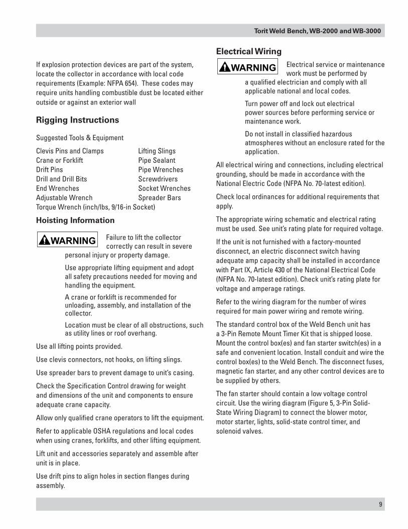
Hoisting Information
Failure to lift the collector correctly can result in severe
personal injury or property damage.
Use appropriate lifting equipment and adopt all safety precautions needed for moving and handling the equipment.
A crane or forklift is recommended for unloading, assembly, and installation of the collector.
Location must be clear of all obstructions, such as utility lines or roof overhang.
Use all lifting points provided.
Use clevis connectors, not hooks, on lifting slings.
Use spreader bars to prevent damage to unit’s casing.
Check the Specification Control drawing for weight and dimensions of the unit and components to ensure adequate crane capacity.
Allow only qualified crane operators to lift the equipment.
Refer to applicable OSHA regulations and local codes when using cranes, forklifts, and other lifting equipment.
Lift unit and accessories separately and assemble after unit is in place.
Use drift pins to align holes in section flanges during assembly.
Electrical WiringElectrical service or maintenance work must be performed by
a qualified electrician and comply with all applicable national and local codes.
Turn power off and lock out electrical power sources before performing service or maintenance work.
Do not install in classified hazardous atmospheres without an enclosure rated for the application.
All electrical wiring and connections, including electrical grounding, should be made in accordance with the National Electric Code (NFPA No. 70-latest edition).
Check local ordinances for additional requirements that apply.
The appropriate wiring schematic and electrical rating must be used. See unit’s rating plate for required voltage.
If the unit is not furnished with a factory-mounted disconnect, an electric disconnect switch having adequate amp capacity shall be installed in accordance with Part IX, Article 430 of the National Electrical Code (NFPA No. 70-latest edition). Check unit’s rating plate for voltage and amperage ratings.
Refer to the wiring diagram for the number of wires required for main power wiring and remote wiring.
The standard control box of the Weld Bench unit has a 3-Pin Remote Mount Timer Kit that is shipped loose. Mount the control box(es) and fan starter switch(es) in a safe and convenient location. Install conduit and wire the control box(es) to the Weld Bench. The disconnect fuses, magnetic fan starter, and any other control devices are to be supplied by others.
The fan starter should contain a low voltage control circuit. Use the wiring diagram (Figure 5, 3-Pin Solid-State Wiring Diagram) to connect the blower motor, motor starter, lights, solid-state control timer, and solenoid valves.
10
Donaldson Company, Inc.
Standard Equipment
Each Weld Bench is shipped fully assembled from the factory including filters. The Weld Bench unit has two slots for forklift steel fingers to move the unit. The WB-3000 weighs approximately 1,600 lbs. The forklift must be able to safely lift this unit.
The Weld Bench can be located against a wall if preferred. Wherever placed, make sure there are no obstructions on either side of the unit. On one side of the unit there are access covers for the filters and on the other side is the outlet discharge, compressed air fitting, and the clean air plenum access cover.
Sprinkler Head
One ¾” horizontal sprinkler head comes factory installed on the Weld Bench. The sprinkler head is located on the dirty air side section of the unit. Fume contamination may accumulate on the sprinkler head, therefore, monthly inspection is recommended to prevent malfunction in case of a fire. The sprinkler head should be changed annually per the manufacturer’s recommendations. Shut-off valve is supplied and installed by others to control the water supply.
Air Tool Connection
The air tool connection feature is standard on all Weld Bench models. However, air tools should not be used while the unit is in the cleaning mode (see Typical Installation).
Changing air pressure to accommodate air tools will affect filter cleaning. A pressure of 60-90 psig (depending upon filter condition) must be maintained at the Weld Bench compressed air fitting.
Backdraft Panel
The Weld Bench backdraft panel is removable by turning the lift and turn latches and pulling the panel forward. Use the handles to remove the panel. This feature allows the customer to clean the dirty section of the unit. The dirty section consists of the filter deflectors, shroud assembly walls, and the back section of the backdraft panel. The dirty air section should be initially cleaned
after every 8-12 hours of operation. When welding on oily parts, cleaning may be required daily to remove any oily build-up to minimize risk of fire.
Swing Door
Each Weld Bench has a right and left lift-off swing door. This feature will accommodate long workpieces. When working on a small workpiece, it would be helpful to have the swing doors in the closed position for optimum fume capture.
Light Pack (Industrial Light Fixture—Standard Option)
The light fixture is shipped without a fluorescent bulb. The bulb must be supplied by the user.
When the optional control panel and the optional light fixture are ordered, the light connection is prewired to the factory installed control box. The control box is programmed to have the light on when the fan is running. If a standard control box with a 3-pin timer is used, wire the light fixture to a suitable 120V power supply. If a separate on/off control for the light is required, add a switch to the light circuit as shown [switch to be supplied by others] in Light Wiring Schematic.
Work Surface Grounding
The welding work surface is grounded by eye bolts (2-eye bolts for WB-2000 and 4-eye bolts for WB-3000) that are screwed into the welding work surface. Refer to welding supply operation manual.
Torit Weld Bench, WB-2000 and WB-3000
11
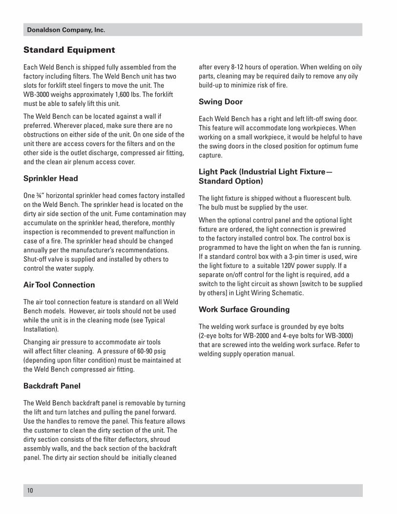
Industrial Light Fixture(Standard Option)
Eye Bolt
Sprinkler Head Connection
Lift-Off Hinge
Backdraft Panel
Swing Door
Swing Door, Backdraft Panel, Lift-Off Hinge, Light Fixture—Standard Option, Sprinkler Head, and Eye Bolt (WB-3000 Shown)
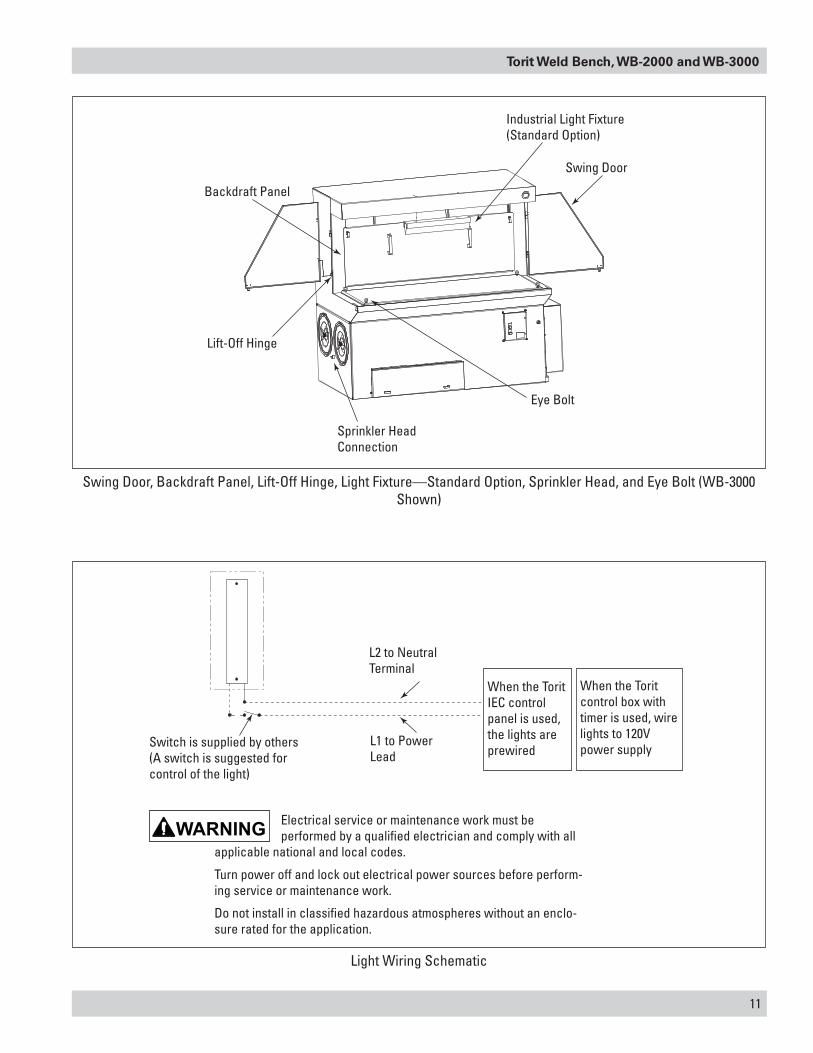
Switch is supplied by others(A switch is suggested for control of the light)
Electrical service or maintenance work must be performed by a qualified electrician and comply with all
applicable national and local codes.
Turn power off and lock out electrical power sources before perform-ing service or maintenance work.
Do not install in classified hazardous atmospheres without an enclo-sure rated for the application.
L1 to PowerLead
L2 to Neutral Terminal
When the ToritIEC control panel is used, the lights are prewired
When the Toritcontrol box with timer is used, wire lights to 120V power supply
Light Wiring Schematic
12
Donaldson Company, Inc.
Compressed Air Installation
Turn compressed-air supply OFF and bleed lines before
performing service or maintenance work.
A safety exhaust valve should be used to isolate the compressed air supply. The safety exhaust valve should completely exhaust downstream pressure when closed and include provisions to allow closed-position locking.
Do not set compressed-air pressure above 100-psig.
Component damage can occur.
All compressed air components must be sized to meet the maximum system requirements of 90-psig supply pressure.
The compressed-air supply must be oil and moisture free. Contamination in the compressed air used to clean filters will result in poor cleaning, cleaning valve failure, or poor collector performance.
Purge compressed-air lines to remove debris before connecting to the unit’s compressed-air manifold.
NOTICE
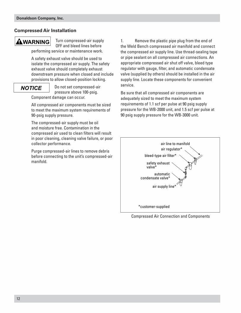
1. Remove the plastic pipe plug from the end of the Weld Bench compressed air manifold and connect the compressed air supply line. Use thread-sealing tape or pipe sealant on all compressed air connections. An appropriate compressed air shut off valve, bleed type regulator with gauge, filter, and automatic condensate valve (supplied by others) should be installed in the air supply line. Locate these components for convenient service.
Be sure that all compressed air components are adequately sized to meet the maximum system requirements of 1.1 scf per pulse at 90 psig supply pressure for the WB-2000 unit, and 1.5 scf per pulse at 90 psig supply pressure for the WB-3000 unit.
Compressed Air Connection and Components
air regulator*air line to manifold
bleed-type air filter*
automatic condensate valve*
air supply line*
safety exhaustvalve*
*customer-supplied
Torit Weld Bench, WB-2000 and WB-3000
13
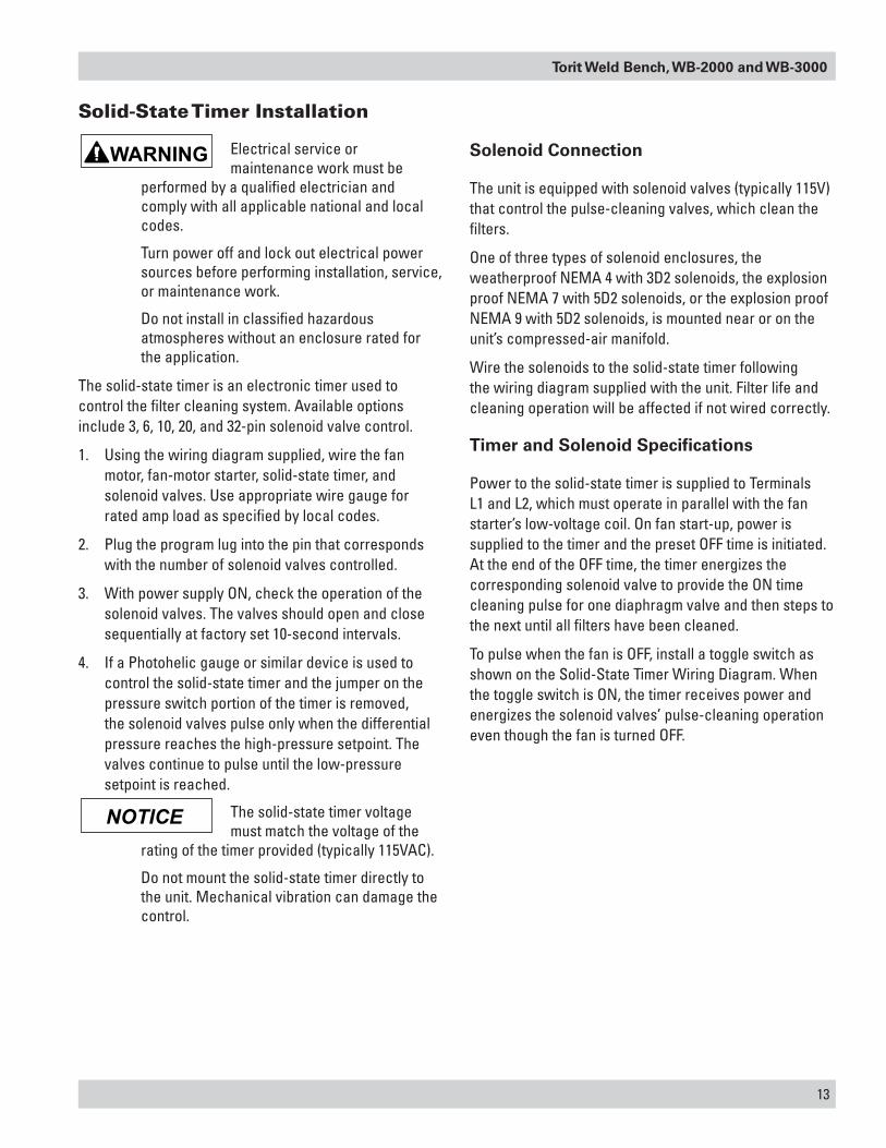
Solid-State Timer Installation
Electrical service or maintenance work must be
performed by a qualified electrician and comply with all applicable national and local codes.
Turn power off and lock out electrical power sources before performing installation, service, or maintenance work.
Do not install in classified hazardous atmospheres without an enclosure rated for the application.
The solid-state timer is an electronic timer used to control the filter cleaning system. Available options include 3, 6, 10, 20, and 32-pin solenoid valve control.
1. Using the wiring diagram supplied, wire the fan motor, fan-motor starter, solid-state timer, and solenoid valves. Use appropriate wire gauge for rated amp load as specified by local codes.
2. Plug the program lug into the pin that corresponds with the number of solenoid valves controlled.
3. With power supply ON, check the operation of the solenoid valves. The valves should open and close sequentially at factory set 10-second intervals.
4. If a Photohelic gauge or similar device is used to control the solid-state timer and the jumper on the pressure switch portion of the timer is removed, the solenoid valves pulse only when the differential pressure reaches the high-pressure setpoint. The valves continue to pulse until the low-pressure setpoint is reached.
The solid-state timer voltage must match the voltage of the
rating of the timer provided (typically 115VAC).
Do not mount the solid-state timer directly to the unit. Mechanical vibration can damage the control.
Solenoid Connection
The unit is equipped with solenoid valves (typically 115V) that control the pulse-cleaning valves, which clean the filters.
One of three types of solenoid enclosures, the weatherproof NEMA 4 with 3D2 solenoids, the explosion proof NEMA 7 with 5D2 solenoids, or the explosion proof NEMA 9 with 5D2 solenoids, is mounted near or on the unit’s compressed-air manifold.
Wire the solenoids to the solid-state timer following the wiring diagram supplied with the unit. Filter life and cleaning operation will be affected if not wired correctly.
Timer and Solenoid Specifications
Power to the solid-state timer is supplied to Terminals L1 and L2, which must operate in parallel with the fan starter’s low-voltage coil. On fan start-up, power is supplied to the timer and the preset OFF time is initiated. At the end of the OFF time, the timer energizes the corresponding solenoid valve to provide the ON time cleaning pulse for one diaphragm valve and then steps to the next until all filters have been cleaned.
To pulse when the fan is OFF, install a toggle switch as shown on the Solid-State Timer Wiring Diagram. When the toggle switch is ON, the timer receives power and energizes the solenoid valves’ pulse-cleaning operation even though the fan is turned OFF.
NOTICE
14
Donaldson Company, Inc.
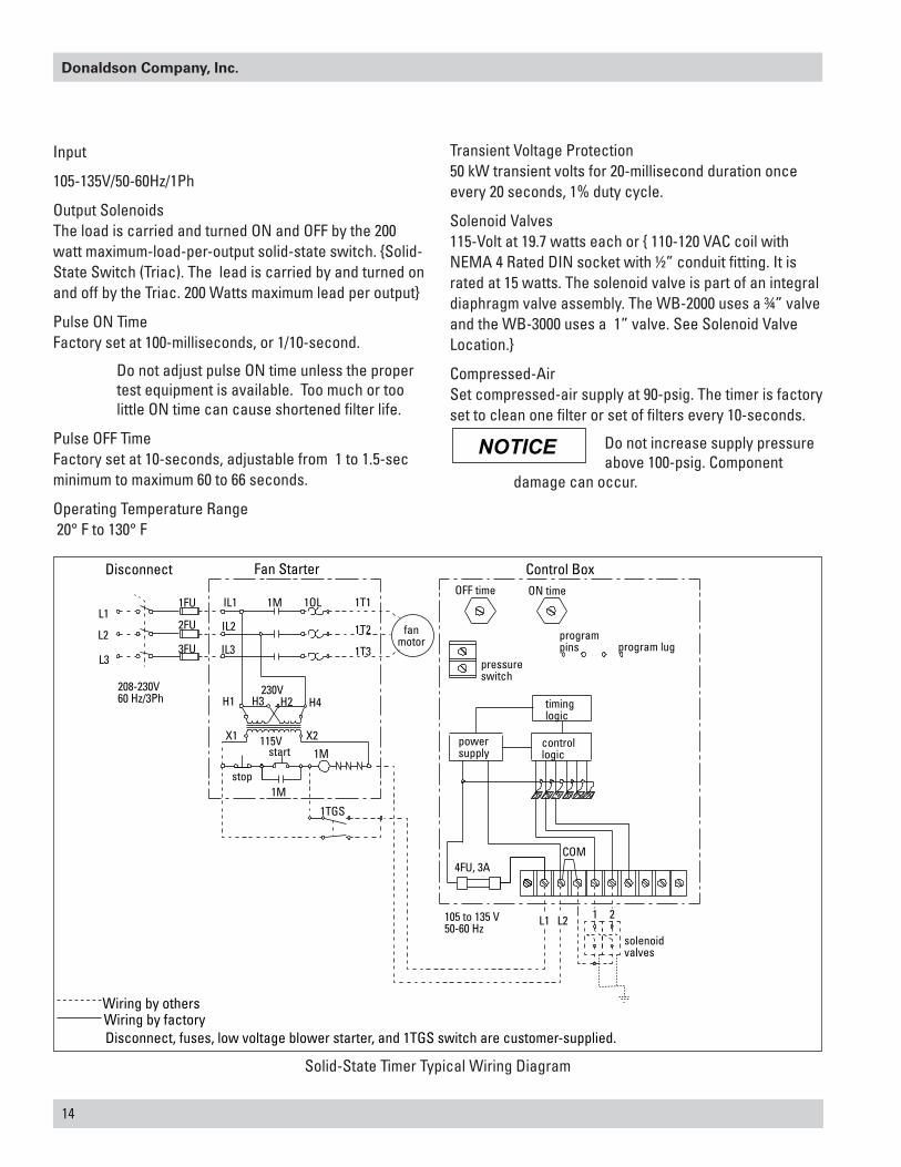
Solid-State Timer Typical Wiring Diagram
Fan Starter Control BoxDisconnect
1FU
2FU
3FU
208-230V60 Hz/3Ph
IL1
IL2
IL3
1M 1OL 1T1
1T2
1T3
230V
115V
H1 H2H3 H4
X1 X2
stop
start
1M
1M
1TGS
fanmotor
OFF time ON time
programpins program lug
pressureswitch
timinglogic
powersupply
controllogic
4FU, 3A
105 to 135 V50-60 Hz
solenoidvalves
COM
L1
L2
L3
Disconnect, fuses, low voltage blower starter, and 1TGS switch are customer-supplied.
Use wiring diagram provided with unit
Wiring by othersWiring by factory
L1 L2 21
Verify if this it the right illustration to use or should it be the one without ground?
Input
105-135V/50-60Hz/1Ph
Output Solenoids The load is carried and turned ON and OFF by the 200 watt maximum-load-per-output solid-state switch. {Solid-State Switch (Triac). The lead is carried by and turned on and off by the Triac. 200 Watts maximum lead per output}
Pulse ON Time Factory set at 100-milliseconds, or 1/10-second.
Do not adjust pulse ON time unless the proper test equipment is available. Too much or too little ON time can cause shortened filter life.
Pulse OFF Time Factory set at 10-seconds, adjustable from 1 to 1.5-sec minimum to maximum 60 to 66 seconds.
Operating Temperature Range 20° F to 130° F
Transient Voltage Protection 50 kW transient volts for 20-millisecond duration once every 20 seconds, 1% duty cycle.
Solenoid Valves 115-Volt at 19.7 watts each or { 110-120 VAC coil with NEMA 4 Rated DIN socket with ½” conduit fitting. It is rated at 15 watts. The solenoid valve is part of an integral diaphragm valve assembly. The WB-2000 uses a ¾” valve and the WB-3000 uses a 1” valve. See Solenoid Valve Location.}
Compressed-Air Set compressed-air supply at 90-psig. The timer is factory set to clean one filter or set of filters every 10-seconds.
Do not increase supply pressure above 100-psig. Component
damage can occur.
NOTICE
Torit Weld Bench, WB-2000 and WB-3000
15
Solid-State Control Timer Specifications Standard Option
Optional Switch 1TGS: Closure of switch 1TGS applies power to the timer control circuit board, which is in parallel with the low voltage coil of the fan magnetic starter. Supplying power initiates the control circuit boards’ preset OFF time. At the end of the OFF time, a solenoid will be energized to provide the cleaning pulse for one segment of filter elements and then step to the next segment. This cycle continues until the Weld Bench fan starter is turned off or an auxiliary switch (not supplied) opens. Make sure that the programming pin on the control circuit board is located on the correct number of solenoid valves being used.
After shift pulsing:
In most applications, pulsing after shutdown provides adequate cleaning. The Solid-State Control Timer can be wired to pulse filters only when the fan is turned off. This is accomplished by wiring the Solid-State Timer through a manual switch to a separate power source. Other options include using an auxiliary contact on the blower motor starter and timers to automate the cleaning process.
Optional IEC Control Panel
Electrical service or maintenance work must be
performed by a qualified electrician and comply with all applicable national and local codes.
Turn power off and lock out electrical power sources before performing service or maintenance work.
Do not install in classified hazardous atmospheres without an enclosure rated for the application.
Optional IEC Control Panels using programmable logic circuits are factory installed and are available for 3 Hp and 5 Hp with all the different voltages. The IEC Control Panel consists of a motor starter with branch circuit and overload protection, control power transformer with
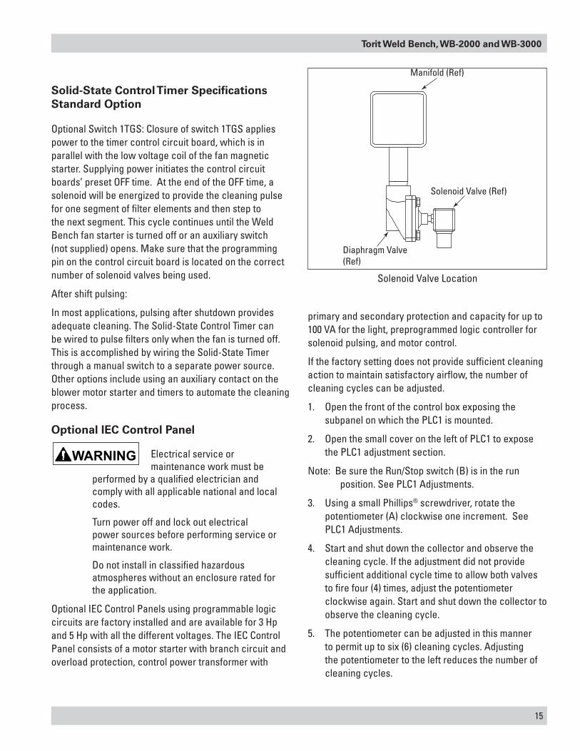
Solenoid Valve Location
Manifold (Ref)
Solenoid Valve (Ref)
Diaphragm Valve (Ref)
primary and secondary protection and capacity for up to 100 VA for the light, preprogrammed logic controller for solenoid pulsing, and motor control.
If the factory setting does not provide sufficient cleaning action to maintain satisfactory airflow, the number of cleaning cycles can be adjusted.
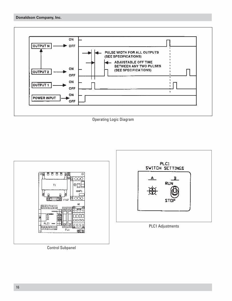
1. Open the front of the control box exposing the subpanel on which the PLC1 is mounted.
2. Open the small cover on the left of PLC1 to expose the PLC1 adjustment section.
Note: Be sure the Run/Stop switch (B) is in the run position. See PLC1 Adjustments.
3. Using a small Phillips® screwdriver, rotate the potentiometer (A) clockwise one increment. See PLC1 Adjustments.
4. Start and shut down the collector and observe the cleaning cycle. If the adjustment did not provide sufficient additional cycle time to allow both valves to fire four (4) times, adjust the potentiometer clockwise again. Start and shut down the collector to observe the cleaning cycle.
5. The potentiometer can be adjusted in this manner to permit up to six (6) cleaning cycles. Adjusting the potentiometer to the left reduces the number of cleaning cycles.
16
Donaldson Company, Inc.
Operating Logic Diagram
Control Subpanel
PLC1 Adjustments
Torit Weld Bench, WB-2000 and WB-3000
17
Preliminary Start-Up Check
Instruct all personnel on safe use and maintenance procedures.
Electrical work during installation must be performed
by a qualified electrician and comply with all applicable national and local codes.
Turn power off and lock out electrical power sources before performing service or maintenance work.
Turn compressed air supply OFF and bleed lines before performing service or maintenance work
Check that the collector is clear and free of all debris before starting.
Do not install in classified hazardous atmospheres without an enclosure rated for the application.
Optional fans over 600 lbs must be independently supported.
1. Check all electrical connections for tightness and contact.
2. Motor and fan should be wired for clockwise rotation when viewed from the back of the motor.
To reverse rotation, single-phase power supply: Follow manufacturer’s instructions on the motor’s nameplate.
To reverse rotation, three-phase power supply: Turn electrical power OFF at source and switch any two leads on the motor junction box.
Do not interchange a power lead with the ground wire. Severe
damage or personal injury may result.
3. All access panels should be sealed and secure.
4. Check that the dust container is properly sealed and clamped.
5. Check that exhaust damper is set to the fully-closed position.
6. Check and remove all loose items in or near the inlet and outlet of the unit.
7. Check that all remote controls and solenoid enclosures (if applicable) are properly wired and all service switches are in the OFF position.
8. Check that all optional accessories are installed properly and secured.
9. Turn power ON at source.
10. Turn the compressed-air supply ON. Adjust pressure regulator for 60-psig.
11. Turn blower fan motor ON.
Do not look into fan outlet to determine rotation. View the fan
rotation through the back of the motor.
Check that the exhaust plenum is free of tools or debris before checking blower/fan rotation.
Stand clear of exhaust to avoid personal injury.
12. Adjust airflow with the exhaust damper.
Excess airflow can shorten filter life, cause electrical system
failure, and blower motor failure.
Is the rest of this page needed?
5. Start blower motor and check operation of the solenoid valves. With the Solid-State Timer Control installed and the pulse control switch ON, the valves should open and close continuously. The pulse width and time between pulses is factory set.
6. Periodically check the filter pressure drop. For longest element life, they should be cleaned before the filter pressure drop reaches the Red Zone which is set at 4 inches water gauge. Equilibrium filter pressure drop is generally 3 to 5 inches water gauge.
Torit recommends pulse cleaning the filters when the fan is in the spinning down mode.
NOTICE
18
Donaldson Company, Inc.
Operating Adjustments
Do not set compressed-air pressure above 100-psig.
Component damage can occur.
Less than 3 seconds between pulses will cause lack of compressed air supply to the manifold and a loss of cleaning pressure.
Do not increase or decrease the on-time length of pulse. Longer pulses do not aid cleaning, they simply waste compressed air and shorten filter life. Shorter pulses will not deliver enough energy to clean the filters.
Higher compressed air pressure is allowed if filter equilibrium pressure drop stays at the red zone. Increase compressed air pressure in 10-psig increments to maximum of 90-psig. Allow time for pressure drop to stabilize after each 10-psig increase. Do not increase air pressure above 100-psig.
The control timer is factory set to clean a row of elements every 10 seconds. Pressure drop can often be lowered by increasing the frequency of cleaning. The minimum time between pulses is 3 seconds.
Maintenance Information
Instruct all personnel on safe use and maintenance procedures.
Use proper equipment and adopt all safety precautions needed
for servicing equipment. Electrical service or maintenance work must be performed by a qualified electrician and comply with all applicable national and local codes.
Turn power off and lock out electrical power sources before performing service or maintenance work.
Do not install in classified hazardous atmospheres without an enclosure rated for the application.
Turn compressed air supply OFF and bleed lines before performing service or maintenance work.
Do not set compressed-air pressure above 100-psig.
Component damage can occur.
All compressed air components must be sized to meet the maximum system requirements of 90-100 psig supply pressure.
The compressed-air supply must be oil and moisture free. Contamination in the compressed air used to clean filters will result in poor cleaning, cleaning valve failure, or poor collector performance.
Purge compressed air lines to remove debris before connecting to the unit’s compressed air manifold.
Operational Checklist
1. Monitor the physical condition of the collector and repair or replace any damaged components.
Routine inspections will minimize downtime and maintain optimum system performance. This is particularly important on continuous-duty applications.
Periodically check the compressed air components and replace compressed air filters.
Drain moisture following the manufacturer’s instructions. With the compressed air supply ON, check the cleaning valves, solenoid valves, and tubing for leaks. Replace as necessary.
2. Monitor pressure drop across filters.
Abnormal changes in pressure drop indicate a change in operating conditions and possibly a fault to be corrected. For example, prolonged lack of compressed air will cause an excess build-up of dust on the filters resulting in increased pressure drop. Cleaning off-line with no flow usually restores the filters to normal pressure drop.
3. Monitor exhaust.
4. Monitor dust disposal.
NOTICE NOTICE
Torit Weld Bench, WB-2000 and WB-3000
19
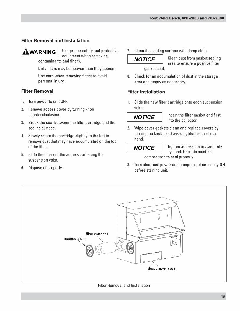
Filter Removal and Installation
Use proper safety and protective equipment when removing
contaminants and filters.
Dirty filters may be heavier than they appear.
Use care when removing filters to avoid personal injury.
Filter Removal
1. Turn power to unit OFF.
2. Remove access cover by turning knob counterclockwise.
3. Break the seal between the filter cartridge and the sealing surface.
4. Slowly rotate the cartridge slightly to the left to remove dust that may have accumulated on the top of the filter.
5. Slide the filter out the access port along the suspension yoke.
6. Dispose of properly.
7. Clean the sealing surface with damp cloth.
Clean dust from gasket sealing area to ensure a positive filter
gasket seal.
8. Check for an accumulation of dust in the storage area and empty as necessary.
Filter Installation
1. Slide the new filter cartridge onto each suspension yoke.
Insert the filter gasket end first into the collector.
2. Wipe cover gaskets clean and replace covers by turning the knob clockwise. Tighten securely by hand.
Tighten access covers securely by hand. Gaskets must be
compressed to seal properly.
3. Turn electrical power and compressed air supply ON before starting unit.
NOTICE
NOTICE
NOTICE
filter cartridge
dust drawer cover
access cover
Filter Removal and Installation
20
Donaldson Company, Inc.
Filter Cleaning
The Weld Bench is available with the optional IEC Control Panel which is factory installed and programmed to clean the unit every time the unit is shutting down. The IEC Control Panel is programmed for three (3) cleaning cycles. Field adjustments can be made to increase the number of cleaning cycles to a maximum of six (6) (see Optional IEC Control Panel).
There is one pulse solenoid and diaphragm valve per filter row.
The first pulse will occur on the filter row nearer the operator and will start 3 seconds after the power switch is off.
The second pulse will be on the row further from the operator and will start 13 seconds after the power switch is off.
After both rows have pulsed, the fan will automatically start again for a period of time and then shut down.
The pulse/fan start cycle will repeat itself two more times.
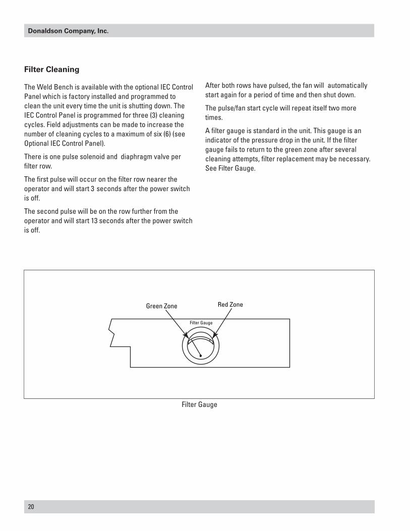
A filter gauge is standard in the unit. This gauge is an indicator of the pressure drop in the unit. If the filter gauge fails to return to the green zone after several cleaning attempts, filter replacement may be necessary. See Filter Gauge.
Green Zone
Filter Gauge
Red Zone
Filter Gauge
Torit Weld Bench, WB-2000 and WB-3000
21
Dust Removal
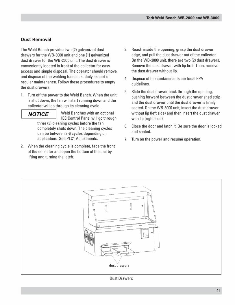
The Weld Bench provides two (2) galvanized dust drawers for the WB-3000 unit and one (1) galvanized dust drawer for the WB-2000 unit. The dust drawer is conveniently located in front of the collector for easy access and simple disposal. The operator should remove and dispose of the welding fume dust daily as part of regular maintenance. Follow these procedures to empty the dust drawers:
1. Turn off the power to the Weld Bench. When the unit is shut down, the fan will start running down and the collector will go through its cleaning cycle.
Weld Benches with an optional IEC Control Panel will go through
three (3) cleaning cycles before the fan completely shuts down. The cleaning cycles can be between 3-6 cycles depending on application. See PLC1 Adjustments.
2. When the cleaning cycle is complete, face the front of the collector and open the bottom of the unit by lifting and turning the latch.
3. Reach inside the opening, grasp the dust drawer edge, and pull the dust drawer out of the collector. On the WB-3000 unit, there are two (2) dust drawers. Remove the dust drawer with lip first. Then, remove the dust drawer without lip.
4. Dispose of the contaminants per local EPA guidelines.
5. Slide the dust drawer back through the opening, pushing forward between the dust drawer shed strip and the dust drawer until the dust drawer is firmly seated. On the WB-3000 unit, insert the dust drawer without lip (left side) and then insert the dust drawer with lip (right side).
6. Close the door and latch it. Be sure the door is locked and sealed.
7. Turn on the power and resume operation.
NOTICE
dust drawers
Dust Drawers
22
Donaldson Company, Inc.
Split Taper™ Bushing Mounting Instructions
Many fans are furnished with split taper bushings for mounting the impeller to the shaft. When properly assembled, the bushings grip the hub with a positive clamping action.
1. Bushel barrel and bore of impeller are tapered to ensure concentric mounting and a true running propeller.
2. Capscrews, when tightened, lock bushing in propeller. Use special plated capscrews and nylock nuts.
Bushing No. Bolt Size Torque Ft-Lbs
QT/QH/L/H 1/4-20 7-1/2
3. Bushing is split so that when the locking capscrews force bushing into tapered bore, the bushing grips the shaft with a positive clamping fit. This will withstand vibration and heavy loads without being loosened.
4. Impeller and bushing assembly is keyed to the shaft and held in place by compression, which adds driving strength.
Before assembly, ensure shaft and keyway are clean and
smooth. Check key size with both shaft and bushing keyway.
5. To assemble, insert the capscrews through the clearance holes in the bushing and install bushing loosely into the impeller. Do not press or drive. Start capscrews by hand, turning them just enough to engage threads in the nylock nut. Do not use a wrench at this time. The bushing should be loose enough in the propeller to move freely. Slide impeller and bushing assembly onto shaft, allowing adequate clearance for shaft end play to prevent friction. Fit key into keyway. Do not force impeller and bushing onto shaft. If it does not go on easily, check shaft, bushing, and key sizes once again.
Tighten capscrews gradually and evenly with wrench similar to mounting an automobile wheel. Rotate a quarter turn on each capscrew successively until
all capscrews are tight. These capscrews force the taper bushing into the hub, which in turn compresses the bushing onto the shaft. This makes a positive clamping fit. The torque must not exceed the value specified in the table.
Do not attempt to pull bushing flange flush with hub end.
There should be a clearance which varies approximately 3/16-in to 1/4-in with the bushing size when tightened. This is not a locating dimension.
Impeller Assembly Removal
1. Remove all capscrews from impeller and hub assembly.
2. Insert capscrews into the threaded holes in the bushing flange.
3. Tighten each bolt in quarter of a turn increments to push the impeller off the bushing. This forces the bushing loose from the propeller hub and releases the compression so that the entire assembly will slide from the shaft.
4. Pull the bushing off the shaft.
If the assembly has been in place sometime it may be necessary
to use a wheel puller to remove the bushing. Never use a wheel puller on the impeller.
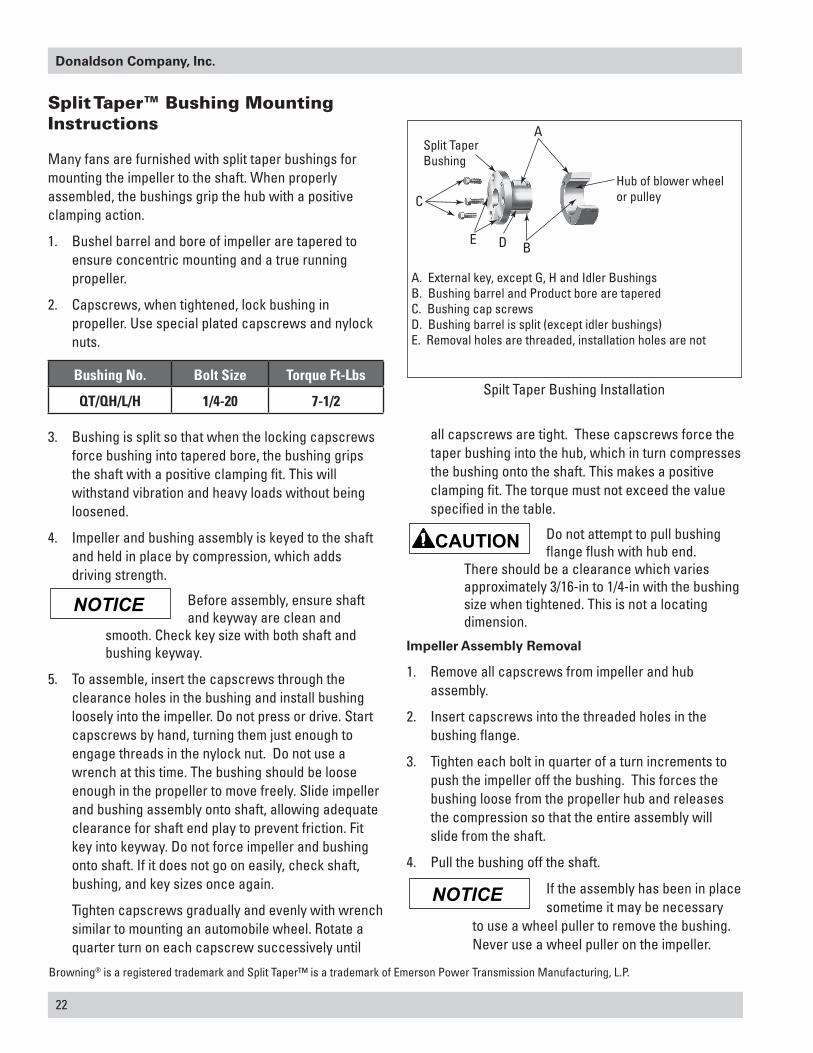
Split TaperBushing
C
A
E D B
A. External key, except G, H and Idler BushingsB. Bushing barrel and Product bore are taperedC. Bushing cap screwsD. Bushing barrel is split (except idler bushings)E. Removal holes are threaded, installation holes are not
Hub of blower wheelor pulley
Spilt Taper Bushing Installation
Browning® is a registered trademark and Split Taper™ is a trademark of Emerson Power Transmission Manufacturing, L.P.
NOTICE
NOTICE
Torit Weld Bench, WB-2000 and WB-3000
23
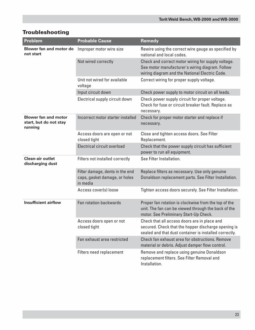
TroubleshootingProblem Probable Cause Remedy
Blower fan and motor do not start
Improper motor wire size Rewire using the correct wire gauge as specified by national and local codes.
Not wired correctly Check and correct motor wiring for supply voltage. See motor manufacturer's wiring diagram. Follow wiring diagram and the National Electric Code.
Unit not wired for available voltage
Correct wiring for proper supply voltage.
Input circuit down Check power supply to motor circuit on all leads.Electrical supply circuit down Check power supply circuit for proper voltage.
Check for fuse or circuit breaker fault. Replace as necessary.
Blower fan and motor start, but do not stay running
Incorrect motor starter installed Check for proper motor starter and replace if necessary.
Access doors are open or not closed tight
Close and tighten access doors. See Filter Replacement.
Electrical circuit overload Check that the power supply circuit has sufficient power to run all equipment.
Clean-air outlet discharging dust
Filters not installed correctly See Filter Installation.
Filter damage, dents in the end caps, gasket damage, or holes in media
Replace filters as necessary. Use only genuine Donaldson replacement parts. See Filter Installation.
Access cover(s) loose Tighten access doors securely. See Filter Installation.
Insufficient airflow Fan rotation backwards Proper fan rotation is clockwise from the top of the unit. The fan can be viewed through the back of the motor. See Preliminary Start-Up Check.
Access doors open or not closed tight
Check that all access doors are in place and secured. Check that the hopper discharge opening is sealed and that dust container is installed correctly.
Fan exhaust area restricted Check fan exhaust area for obstructions. Remove material or debris. Adjust damper flow control.
Filters need replacement Remove and replace using genuine Donaldson replacement filters. See Filter Removal and Installation.
24
Donaldson Company, Inc.
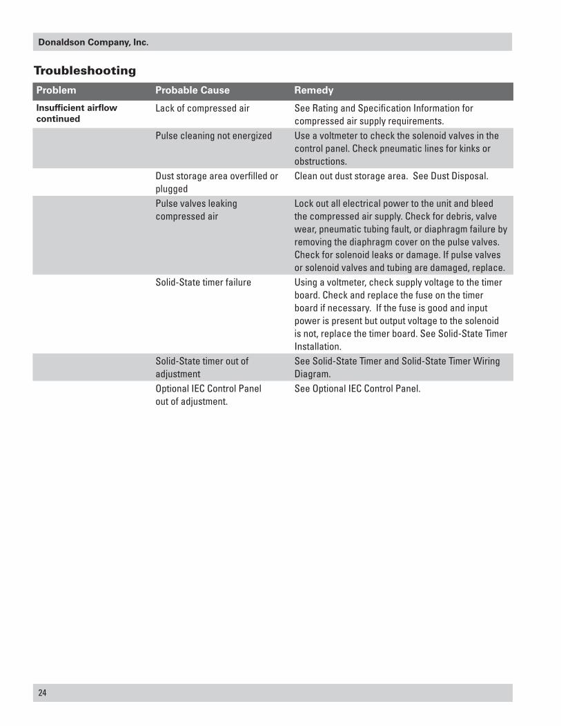
Problem Probable Cause Remedy
Insufficient airflow continued
Lack of compressed air See Rating and Specification Information for compressed air supply requirements.
Pulse cleaning not energized Use a voltmeter to check the solenoid valves in the control panel. Check pneumatic lines for kinks or obstructions.
Dust storage area overfilled or plugged
Clean out dust storage area. See Dust Disposal.
Pulse valves leaking compressed air
Lock out all electrical power to the unit and bleed the compressed air supply. Check for debris, valve wear, pneumatic tubing fault, or diaphragm failure by removing the diaphragm cover on the pulse valves. Check for solenoid leaks or damage. If pulse valves or solenoid valves and tubing are damaged, replace.
Solid-State timer failure Using a voltmeter, check supply voltage to the timer board. Check and replace the fuse on the timer board if necessary. If the fuse is good and input power is present but output voltage to the solenoid is not, replace the timer board. See Solid-State Timer Installation.
Solid-State timer out of adjustment
See Solid-State Timer and Solid-State Timer Wiring Diagram.
Optional IEC Control Panel out of adjustment.
See Optional IEC Control Panel.
Troubleshooting
Torit Weld Bench, WB-2000 and WB-3000
25
Service Notes
Date Service Performed Notes
26
Donaldson Company, Inc.
Service Notes
Date Service Performed Notes

Donaldson Company, Inc. is the leading designer and manufacturer of dust, mist, and fume collection equipment used to control industrial-air pollutants. Our equipment is designed to help reduce occupational hazards, lengthen machine life, reduce in-plant maintenance requirements, and improve product quality.
© 2000 Donaldson Company, Inc. IOM 9335001, Revision 4Printed in USA March 2011
Parts and Service
For genuine Donaldson replacement filters and parts, call the Parts Express Line. For faster service, have unit’s model and serial number, quantity, part number, and description available.
Donaldson Company, Inc.ToritPO Box 1299Minneapolis, MN 55440-1299U.S.A.
The Donaldson Torit Warranty
Donaldson warrants to the original purchaser that the major structural components of the goods will be free from defects in materials and workmanship for ten (10) years from the date of shipment, if properly installed, maintained and operated under normal conditions. Donaldson warrants all other Donaldson built components and accessories including Donaldson Airlocks, TBI Fans, TRB Fans, Fume Collector products, Donaldson built electrical control components and Donaldson built Afterfilter housings for twelve (12) months from date of shipment. Donaldson warrants Donaldson built filter elements to be free from defects in materials and workmanship for eighteen (18) months from date of shipment. Donaldson does not warrant against damages due to corrosion, abrasion, normal wear and tear, product modification, or product misapplication. Donaldson also makes no warranty whatsoever as to any goods manufactured or supplied by others including electric motors, fans and control components. After Donaldson has been given adequate opportunity to remedy any defects in material or workmanship, Donaldson retains the sole option to accept return of the goods, with freight paid by the purchaser, and to refund the purchase price for the goods after confirming the goods are returned undamaged and in usable condition. Such a refund will be in the full extent of Donaldson’s liability. Donaldson shall not be liable for any other costs, expenses or damages whether direct, indirect, special, incidental, consequential or otherwise. The terms of this warranty may be modified only by a special warranty document signed by a Director, General Manager or Vice President of Donaldson. Failure to use genuine Donaldson replacement parts may void this warranty. THERE EXIST NO OTHER REPRESENTATIONS, WARRANTIES OR GUARANTEES EXCEPT AS STATED IN THIS PARAGRAPH AND ALL OTHER WARRANTIES INCLUDING MERCHANTABILITY AND FITNESS FOR A PARTICULAR PURPOSE, WHETHER EXPRESS OR IMPLIED ARE HEREBY EXPRESSLY EXCLUDED AND DISCLAIMED.
800-365-1331 USA 800-343-3639 within Mexico
[email protected] donaldsontorit.com