Embed Size (px)
Citation preview

Installation and Operation Manual
EL Ferro-Resonant Charger
PN 047-0208 rev 112612

1

2
5 Year
POWERHOUSE CHARGERS INDUSTRIAL CHARGER WARRANTY
V Series Charger Models
This Warranty Agreement entered into between POWERHOUSE CHARGERS and the Original End User is with respect to POWERHOUSE CHARGERS motive power battery charger product lines as stated above, for industrial electrical truck battery charging usage.
1.0 GENERAL: POWERHOUSE CHARGERS warrants that each new industrial battery charger supplied by it, is of good workmanship and is free from any inherent mechanical defects, provided:
1.1 The product is installed and operated in accordance with generally accepted industrial standards and in accordance with the printed instructions supplied with the charger.
1.2 The charger is used under conditions for which it was designed and is not subject to misuse, negligence or accident.
1.3 The charger receives proper care, protection, and maintenance under supervision of competent personnel.
1.4 The charger is used within the published performance rating for the unit involved.
1.5 The charger is used exclusively by the original end-user and by no other persons.
2.0 PERSONS COVERED: The charger is fully warranted for 5 years from the date of shipment by POWERHOUSE CHARGERS to the original end user, with the following exceptions:
2.1 Primary switch contacts, fuses, bulbs, and filters are not warranted unless found to be defective prior to use.
3.0 LIMITATION OF REMEDY Any claimed defect is subject to POWERHOUSE CHARGERS's inspection and judgment, after the original user at its expense has returned the defective product to POWERHOUSE CHARGERS, St. Louis, MO.
3.1 POWERHOUSE CHARGERS's liability is limited to the repair of the defect or, at POWERHOUSE CHARGERS's option, the replacement of the defective parts. During the 5-year warranty period, POWERHOUSE CHARGERS will bear all freight, (within the contiguous 48 states) parts, and labor costs of such repair or replacement. POWERHOUSE CHARGERS shall not be obligated to reimburse the original end user or any other person for any work performed.
3.2 Replacement parts will be warranted for the remainder of the original warranty period as defined above, or for 30 days; whichever is greater.
3.3 POWERHOUSE CHARGERS shall not be liable for direct or indirect, special or consequential damages in excess of such repair or replacement. In no event shall the original end user be entitled to recover for contingent expenses resulting from, but not limited to, telephone calls, faxes, travel expenses, lodging, duties and taxes, labor, rental of replacement equipment, loss of business or profits or other commercial losses.
4.0 USE OF DEFECTIVE PRODUCT: Continued use of a defective charger after discovery of a defect may void all warranties.
5.0 REPAIRED EQUIPMENT: Except as authorized in writing, this warranty does not cover any equipment that has been repaired by any party other than an authorized POWERHOUSE CHARGERS service agent.
6.0 MODIFIED EQUIPMENT: This warranty is void if this equipment has been modified without written permission from POWERHOUSE CHARGERS.
EXCEPT AS STATED ABOVE, ALL OTHER WARRANTIES AND CONDITIONS, EITHER EXPRESS OR IMPLIED, INCLUDING IMPLIED WARRANTIES OR MERCHANTABILITY AND FITNESS FOR A PARTICULAR PURPOSE, ARE EXCLUDED AND ORIGINAL END USER ASSUMES ALL RISK AND LIABILITY RESULTING FROM USE OF THE PRODUCT. POWERHOUSE CHARGERS NEITHER ASSUMES NOR AUTHORIZES ANY PERSON TO ASSUME FOR POWERHOUSE CHARGERS ANY OTHER LIABILITY IN CONNECTION WITH THE SALE OR USE OF THE PRODUCT AND THERE ARE NO ORAL AGREEMENTS OR WARRANTIES COLLATERAL TO OR AFFECTING THIS WRITTEN WARRANTY. WAR_V_111512

3
INDEX
Page Section Description 4 - Safety Instructions 5 1.0 Installation 5 1.1 Receiving 5 1.2 Location 5-6 1.3 Line Voltage Adjustments 7 1.4 AC Service Requirements 7 1.5 Connecting AC Service to Charger 8 1.6 Grounding the Charger 8 1.7 Battery Connector and Charger Cable 8 1.8 Charging Rate Adjustment 9 2.0 Operation 9 -11 2.1 046-0266 Control 12 -13 3.0 Troubleshooting & Maintenance 14 4.0 Replaceable Parts 14 4.1 Ordering Information 14 4.2 Recommended Spares 15 4.3 Spare Parts List 16-17 5.0 Schematics

4
SAFETY INSTRUCTIONS
WARNING THIS EQUIPMENT CONTAINS LETHAL VOLTAGE LEVELS. INSTALLATION AND SERVICING
MUST BE PERFORMED BY QUALIFIED PERSONNEL
IMPORTANT: SAVE THESE INSTRUCTIONS! READ AND FOLLOW ALL INSTRUCTIONS BEFORE INSTALLING, OPERATING, OR
SERVICING CHARGER. ANY DEVIATION CAN CAUSE SERIOUS AND PERMANENT DAMAGE. FAILURE TO FOLLOW THE INSTRUCTIONS VOIDS THE WARRANTY.
1. Install and ground the charger in accordance with the National Electric Code and your local electric
code. Failure to properly ground the charger could result in a fatal electric shock. 2. To reduce the risk of fire, install chargers on a surface of non-combustible material, such as concrete,
stone, brick or grounded metal. 3. This charger has been designed to only charge flooded, lead-acid batteries. It should not be used for
charging other types of flooded batteries or sealed batteries. 4. Connect only batteries of the same number of cells and ampere-hour rating as listed on the charger
nameplate. Damage to the battery could occur, particularly if the battery has fewer cells than the rating of the charger.
5. Do not touch uninsulated parts of the output connector or battery terminals. A possibility of serious
electrical shock exists. 6. During charge, batteries produce hydrogen gas, which can explode if ignited. Never smoke, use an
open flame, or create sparks in the vicinity of the battery. Ventilate well when the battery is in an enclosed space.
7. Do not connect or disconnect the battery plug while the charger is on. Doing so will cause arching
and burning of the connector resulting in charger damage or battery explosion. 8. Lead-acid batteries contain sulfuric acid, which is caustic and can cause chemical burns to the skin.
Refer to the battery manufacturers instructions for safe handling of batteries. Use proper personnel protective equipment. Do not get in eyes, on skin, or on clothing. In cases of contact with eyes, flush immediately with clean water for 15 minutes. Seek medical attention immediately.
9. Do not operate the charger with the door open or with any panels removed. De-energize all AC and
DC power connections before servicing the charger. 10. The charger is not for outdoor use. Do not expose the charger to water spray, rain or snow. 11. Do not operate the charger with damaged cables, including cables with exposed conductors or
damaged connectors. Replace damaged cables before operation. 12. Do not operate the charger if it has been dropped, received a sharp blow, or otherwise damaged in
any way. Call your service representative.

5
SECTION 1 - INSTALLATION 1.1. Receiving Immediately upon receipt of the charger, check it against the shipping invoice to ensure the shipment is complete and undamaged. Examine the outside of the packing for signs of rough handling before accepting the charger from the carrier. If there is evidence of damage, the receipt should be signed, and both copies (carrier's and receiving copies) marked "Shipment Received Damaged". The carrier's representative should be called immediately and asked to make a "Carrier's Damage Report". If concealed damage is later detected, the carrier should be called and requested to make a "Carrier's Inspection for Concealed Damage Report". After inspection by the carrier, arrangements should be made with the charger representative to have the charger repaired before placing it in service. When contacting your charger representative for assistance on a damage claim or shipment error, provide the Model, and Serial Number of the charger, and a full description of the damage or error. It is good practice to move the charger to the installation site before uncrating. When using bars, hammers, etc. for uncrating, use care to avoid damage to the charger. WARNING: To reduce the risk of fire, install the battery charger on a non-combustible surface such as concrete, stone, brick, or steel. DO NOT operate the charger on its shipping skid materials. 1.2. Location For the best operating conditions and longest life, take care in selecting an installation site. Avoid locations exposed to high humidity, temperature extremes or dust. Moisture condensing on machine parts and electrical components can cause corrosion, which seriously affects operation, efficiency and life. All units are designed for floor mounting. Standard cases may be stack-mounted if required, up to 3 high. If so, optional stacking brackets are required and available. Consult factory. Dust and dirt will also decrease heat radiation from heat-generating components, such as transformers and diodes. This will result in higher operating temperatures and shorter life. Adequate air circulation is needed at all times in order to ensure proper operation. Provide a minimum of 6 inches of free air space at the sides and rear of the charger. The front of the charger must remain unobstructed for serviceability. 1.3. Line Voltage Adjustments All chargers are shipped with the AC line voltage jumper wires set for the AC voltage specified on the purchase order. Before connecting the charger to the AC service, it should be verified that the internal AC voltage connections match the available AC service voltage. If necessary change the AC voltage jumper wires shown in Figs. 1.3.1 through 1.3.3.
NOTE: For 50 Hz. Single or three phase fixed voltage chargers, there are no adjustments.
CAUTION: It will be necessary in most cases to change the AC fuses when the AC voltage jumpers are changed. Refer to the fuse chart on the inside door of the charger for the correct fuse rating.
6
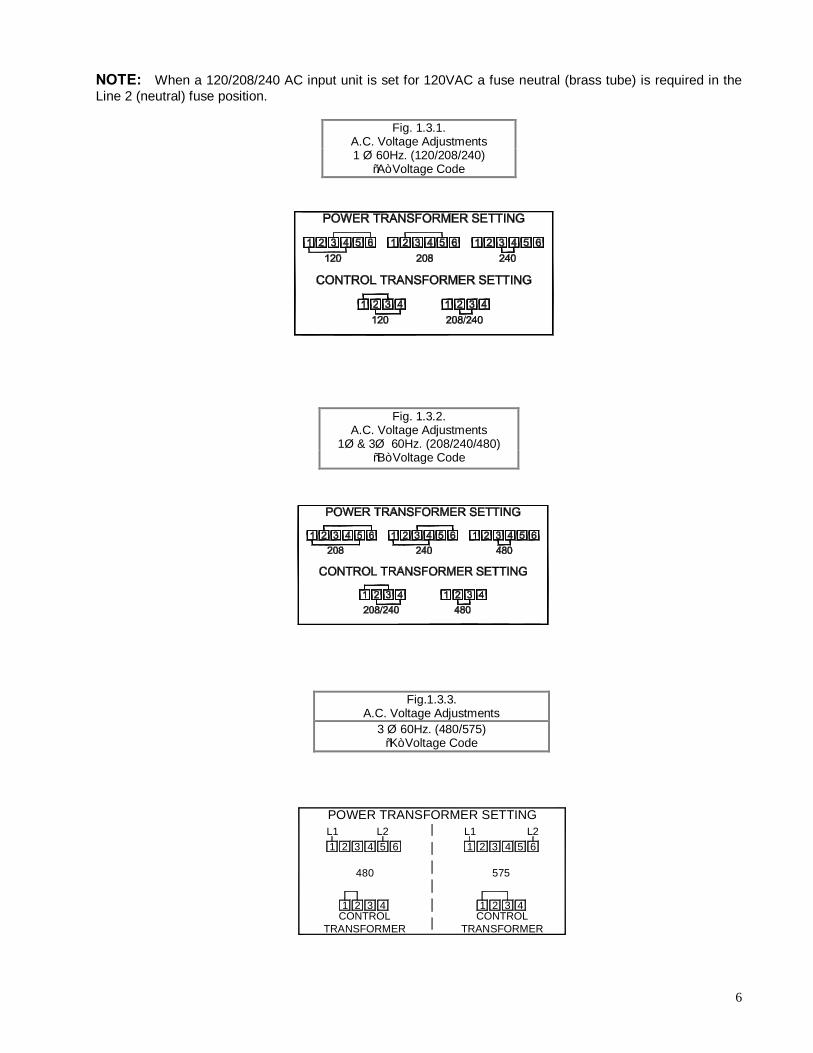
575
POWER TRANSFORMER SETTING
480
L2 L21 2 3 4 5 6 1 2 3 4 5 6L1 L1
1 2 3 4 1 32 4CONTROL
TRANSFORMERCONTROL
TRANSFORMER
NOTE: When a 120/208/240 AC input unit is set for 120VAC a fuse neutral (brass tube) is required in the Line 2 (neutral) fuse position.
Fig. 1.3.1. A.C. Voltage Adjustments 1 Ø 60Hz. (120/208/240)
“A” Voltage Code
Fig. 1.3.2. A.C. Voltage Adjustments
1Ø & 3Ø 60Hz. (208/240/480) “B” Voltage Code
Fig.1.3.3. A.C. Voltage Adjustments
3 Ø 60Hz. (480/575) “K” Voltage Code

7
TABLE 1-1
Line Amperes Disconnect Switch Fuse Size Amps
000.0 - 02.5 30A 05 003.0 - 04.5 30A 07 005.0 - 07.5 30A 10 008.0 - 11.0 30A 15 011.5 - 15.5 30A 20 016.0 - 18.0 30A 25 018.5 - 22.0 30A 30 022.5 - 27.0 60A 35 027.5 - 32.0 60A 40 032.5 - 40.0 60A 50 040.5 - 48.0 60A 60 048.5 - 64.0 80A 80 065.0 - 80.0 100A 100 081.0 - 95.0 125A 125 096.0 - 125.0 150A 150
1.4. AC Service Requirements Follow local code requirements if they are different than the instructions in this manual. After checking the transformer connections as described in Paragraph 1.3, refer to Table 1-1, to determine the correct ratings for the AC cable, AC fuses, and AC service disconnect switch for the line amperes as listed on the nameplate of the charger for the available AC voltage For voltages up to 240, use a 240 volt disconnect switch. For voltages greater than 240 to 600, use a 600 volt disconnect switch.
• Two conductors and ground wire required for single phase. • Three conductors and ground wire required for three-phase
1.5. Connecting AC Service to the Charger 1.5.1 Single-Phase Models Connect the AC service to the L1 and L2 terminals located at the end of the AC fuse block. Note: If the charger has been ordered with an AC input door-mounted disconnect switch, the AC input wires will be connected to the L1 and L3 terminals at the top of the switch body. 1.5.2 Three-Phase Models Connect the AC service to the L1, L2 and L3 terminals located at the end of the AC fuse block. Note: If the charger has been ordered with an AC input door-mounted disconnect switch, the AC input wires will be connected to the L1, L2 and L3 terminals at the top of the switch body.

8
1.6 Grounding the Charger The charger must be grounded to the AC system ground for personnel safety. The green ground wire in the AC input wiring must be connected to the charger ground stud (Identified by a green dot and ground symbol). 1.7 Battery Connector and Charging Cable Verify that the connectors on both the battery and the charger are attached so that the positive output terminal of the charger is connected to the positive battery terminal. CAUTION: If the polarity is reversed, the DC fuse will blow. If in doubt, check the polarity with a DC voltmeter. 1.8 Charging Rate Adjustment Note: Charging rate adjustments may be necessary to compensate for locations of extreme AC line variation or may be used to tailor the charger output for aging batteries. The charging rate has been set at the factory; therefore, field adjustment should not be necessary. If there appears to be a charging rate problem, refer to the troubleshooting chart, Section 4. If it is necessary to either increase or decrease the charging rate, a rate adjustment terminal block is provided on the top rear of the transformer mounting bracket. Change only one step at a time and observe the effect on the battery before making a second change. The charging rate is increased by moving to the next higher tap setting in Table 1-2. The charging rate is decreased by moving to the next lower tap setting. No adjustments should be made without consulting the factory.
TABLE 1-2
CHARGING RATE ADJUSTMENTS
CONNECT RED JUMPER WIRE TO
CONNECT BLACK WIRE TO
OUTPUT
9 12 HIGHEST
9 11
9 10
9 8 NORMAL
12 11
12 10 12 9 LOWEST

9
SECTION 2 - OPERATION The charger utilizes a standard ferro-resonant transformer, which provides isolation from the AC service line and regulates the charging current. The transformer output is connected to a full-wave bridge rectifier assembly, which provides DC charging current to the battery.
The starting charge amps and length of time required for a charge vary depending on the charger model. See the data plate on the charger for information.
2.1.1 046-0266 CONTROL
Feature Summary • Charges flooded lead-acid batteries. • Automatic start when battery is connected. • Automatic stop when charge is finished. • Fully charges partially discharged batteries without overcharging. • Dead battery ‘jump start’ for overly-discharged batteries. • Equalize charge by user request. • Automatic shut-down if battery starts to overheat. • Displays charge status and indications with LED’s.
2.1.2 Control Description The front panel has 3 LED’s (light emitting diodes). A yellow ‘CHARGE’ LED indicates when the charger is charging. A yellow ‘80%’ LED indicates when the battery has reached 80% state of charge. A multi-color ‘STATUS’ LED indicates charger status.
The front panel has a 2 button keypad that is used to manually stop the charge cycle, and to manually select an equalize cycle. A charge can be stopped by pressing the ‘STOP’ button. An equalize charge can be requested by pressing the ‘=’ button and turned off by pressing it again.
CHARGE 80%
=
STATUS
DAILY CHARGECONNECT BATTERY - CHARGER
AUTOMATICALLY STARTS AND STOPS WHEN BATTERY IS CHARGED.
EMERGENCY STOPPRESS THE STOP BUTTON BEFORE
DISCONNECTING THE BATTERY.
STOP
046-0266 Control

10
2.1.3 Operation The control provides fully automatic battery charging.
The standard charging profile for flooded lead-acid batteries has 2 phases. During phase 1 the battery is charged at high current until the battery is 80% charged. Then phase 1 terminates and phase 2 begins. As the battery voltage rises during phase 2, charging current tapers down toward the finish current and the battery voltage starts to flatten out. Phase 2 ends and the charge is terminated when the battery voltage no longer changes. This termination method is called ‘dvdt-didt’.
The control offers several safeguards to protect the battery. If a wrong voltage battery is connected, the charger does not start. A ‘Wrong-Battery-Voltage’ condition is indicated. While charging, if the battery voltage exceeds a profile-specific cut-off value, the charge terminates. If the battery starts to overheat, the charge terminates.
2.1.4 Normal Daily Charge When no battery is connected, the ‘STATUS’ multi-color LED is flashing green. Connecting a battery to the charger will cause the charger to perform a self-diagnostic test to verify the control is working properly. During this time a lamp test is performed causing all LED’s to light. This allows the operator to observe any defective LED’s.
When the self-diagnostic is complete, the charge starts and the yellow ‘CHARGE’ LED lights.
When the battery is 80% charged, the yellow ‘80%’ LED lights and the charger starts phase 2 of the charge cycle. When the charge is finished, the ‘STATUS’ multi-color indicator lights green indicating the battery is ready to be taken.
Warning: Risk of explosion. Do not disconnect the battery while the charger is running. Hydrogen gas produced by the battery during charging can be ignited by arcing that occurs when the battery cable is disconnected.
If the battery must be disconnected before the end of the charge cycle, the charger should be turned off first. Press the ‘STOP’ button, and verify the ‘CHARGE’ LED goes out and the multi-color ‘STATUS’ LED is flashing amber. The battery can then be safely disconnected.
2.1.5 Equalize Charge Over time batteries can develop inequalities in cell charge. This can lower the effective capacity of the battery and shorten life. An equalizing charge re-balances the charge in the battery cells. Perform an equalize charge if any of the following conditions exist:
1. On flooded batteries the specific gravity of any cell at the end of charge is 20 points less than the average of all the cells.
2. The on-charge voltage of any cell at the end of charge is 20 millivolts less than the average of all the cells.
3. The battery has been stored for 30 days.
The control performs an equalize charge when requested manually. First connect the battery and allow the charge to start normally. Then press the ‘=’ button. The yellow ‘CHARGE’ LED will flash. The charge time will be extended to allow the cells to equalize their charge. The equalize cycle can be cleared by again pressing the ‘=’ button. The yellow ‘CHARGE’ LED will remain solid.

11
2.1.6 Charge Indications
The following table shows the various charge indications displayed by the LED’s. If an abnormal charge condition occurs, the charge is terminated.
o = LED Off
• = LED On
“•” = LED Flashing
2.1.7 F3 (Low Battery) Override
If the battery voltage is below 1.6 volts per cell the charger will not start automatically. If this is due to an overly discharged battery of the correct voltage, the F3 indication can be manually overridden by pressing the ‘STOP’ button while the F3 indication (Low Battery) shows on the LED’s.
State CHARGE 80% STATUS Description No Battery o o “•” Waiting for battery to be connected. Lamp Test • • • A battery has been connected and the charger is
performing a self-test prior to starting a charge cycle. Charging Phase
1 (no =) • o o Normal charging. The battery has not reached the 80%
point. An equalize will not be performed for this cycle. Charging Phase
1 (=) “•” o o Normal charging. The battery has not reached the 80%
point. An equalize will be performed for this cycle. Charging Phase
2 (no =) • • o Normal charging. The battery has reached the 80%
point. An equalize will not be performed for this cycle. Charging Phase
2 (=) “•” • o Normal charging. The battery has reached the 80%
point. An equalize will be performed for this cycle. Equalizing “•” “•” o Charger is equalizing the battery.
Charge Complete
o o • The charge cycle is complete and the battery may be taken.
Charge Terminated
o o “•” The charge cycle was terminated by pressing the ‘STOP’ button.
F1 o o • Possible shorted cell or low charging amps. Battery did not reach 80% (2.40 V/C) in allowed time.
F3/F4 o o “•” Low battery voltage, less than 1.60 V/C (F3) or High battery voltage, more than 2.40 V/C (F4) at start up.
F5 o o • No charging current to the battery. F7 o • • Long charge, the charger ran longer than allowed time. F8 “•” o • Charger stayed on when control requested it to shut off.

12
SECTION 3 – TROUBLESHOOTING & GENERAL MAINTENANCE Caution: There are lethal voltages exposed when the charger is energized with the door open. Always disconnect the AC service voltage to the charger before opening the door. The following chart lists the most probable cause of a malfunction. SYMPTOMS AND POSSIBLE CAUSES 3.1. No charging current, the control has no display, contactor does not operate. POSSIBLE CAUSE A. Blown AC fuse. B. No AC service voltage. C. Incorrect AC voltage. D. Control transformer output fuse blown. E. Defective control transformer. F. Defective control board. 3.2. No charging current, control has a display. POSSIBLE CAUSE A. Blown DC fuse. B. Defective ammeter. C. Open battery cell. D. Defective diode. E. Defective capacitor. F. Shorted power transformer secondary. 3.3. AC fuse blows. POSSIBLE CAUSE A. Incorrect fuse rating. B. Incorrect AC voltage. C. Fuse Block holding clips loose. D. Shorted transformer winding. 3.4. DC fuse blows. POSSIBLE CAUSE A. Reversed battery connector. B. Incorrect fuse rating. C. Shorted diode in rectifier assembly. 3.5. Excessive water loss in battery. POSSIBLE CAUSE A. Charging rate is too high. See Section 1.8. B. Charger amp-hour rating exceeds the battery amp-hour rating. C. Battery has defective cells.

13
3.6. Low specific gravity at the end of the charge cycle. POSSIBLE CAUSE A. Battery was over-discharged. B. Charger amp-hour rating is less than the battery AH rating. C. Defective open diode. D. Charging rate is too low. See Section 1.8. E. Battery has defective cells. F. Battery has been over-watered. 3.7. Charger does not turn off when the control terminates the charge cycle. POSSIBLE CAUSE A. Defective control. B. AC contactor has welded contacts. 3.8. General Maintenance The charger requires a minimum of maintenance. Connections and terminals should be kept clean and tight. The charger should be periodically cleaned with an air hose to prevent any excessive dirt build up on components. Care should be taken not to bump or move any adjustments during cleaning. Make sure that both the AC lines and the battery are disconnected before cleaning. The frequency of this type of maintenance depends on the environment in which this unit is installed. If any cabinet sheet metal panels are removed for cleaning, be certain they are properly reinstalled upon completion.

14
SECTION 4 – REPLACEABLE PARTS 4.1 Ordering Information The following information must be supplied when ordering a replacement part from your service agent in order to ensure that the correct part is supplied: A. Model or Spec. number of charger (Located on charger data plate) B. Serial number of charger (Located on charger data plate) C. Schematic reference symbol or part D. Description of part 4.2 Recommended Spares The quantity of spares stocked should be increased as the number of chargers increases. The following chart is the minimum quantity recommended per model for multiple charger installations:
# OF CHARGERS # OF SPARE PARTS KITS
1-3 1
4-10 2
11-25 3
26-50 4
51-100 5
SCHEMATIC REF SYMBOL
DESCRIPTION QUAN. USED QUANTITY RECOMMENDED
ACF AC FUSE, 1 PH. 2 4
ACF AC FUSE, 3 PH. 3 6
DCF DC FUSE 1 2
CONTROL CONTROL BOARD 1 1
AK A.C. CONTACTOR 1 1
SD1,SD2 RECTIFIER ASSEMBLY 1 PH. 1 1
SD1-SD6 RECTIFIER ASSEMBLY 3 PH. 1 1
TP TRANSFORMER, 1 PH. 1 0
TP TRANSFORMER, 3 PH 3 0
C CAPACITOR VARIES 1
CT CONTROL TRANSFORMER 1 1

15
4.3 Spare Parts List
Part Number Description Condensers 008-0002 2 MFD 440 Volt 008-0004 4 MFD 440 Volt 008-0006 6 MFD 440 Volt 008-0008 8 MFD 440 Volt 008-0010 10 MFD 440 Volt 008-0012 12.5 MFD 440 Volt 008-0015 15 MFD 440 Volt 008-0017 17.5 MFD 440 Volt 008-0020 20 MFD 440 Volt 008-0030 30 MFD 440 Volt 008-0040 40 MFD 440 Volt Rectifier Assemblies 024-0152 1PH, CT, 108A 024-0153 1PH, CT, 135A 024-0154 1PH, CT, 156A 024-0156 3PH, CT, 108A 024-0157 3PH, CT, 135A 024-0158 3PH, CT, 156A Contactors 009-0020 30 Amp 3 Pole 009-0021 30 Amp 2 Pole 009-0049 60 Amp 3 Pole Controls 046-0266 V SERIES CONTROL Control Transformers 003-1210 240/480P, 24S, 50 VA 003-1211 120/240P, 24S, 50 VA 003-1213 480/600P, 24S, 50 VA DC (FLAT) Fuses 011-0054 80 Amp, 130 Volt 011-0055 100 Amp, 130 Volt 011-0056 150 Amp, 130 Volt 011-0057 200 Amp, 130 Volt 011-0058 250 Amp, 130 Volt 011-0059 300 Amp, 130 Volt 011-0060 400 Amp, 130 Volt

16
Three Phase Charger Schematic # 02-400

17
Single Phase Charger Schematic # 02-416