Embed Size (px)
Citation preview

INSTALLATION AND OPERATION MANUALSUPER-DUTYFOUR-POST LIFTS Models:HDS-18 / HDS-18X VER B
HDS-27 / HDS-27X VER B
HDS-35 / HDS-35X VER B
HDS-40 / HDS-40X VER B
IMPORTANT SAFETY INSTRUCTIONS SAVE THESE INSTRUCTIONS
PLEASE READ THE ENTIRE CONTENTS OF THIS MANUAL PRIOR TO INSTALLATION AND OPERATION. BY PROCEEDING WITH LIFT INSTALLATION AND OPERATION YOU AGREE THAT YOU FULLY UNDERSTAND AND COMPREHEND THE FULL CONTENTS OF THIS MANUAL. FORWARD THIS MANUAL TO ALL OPERATORS. FAILURE TO OPERATE THIS EQUIPMENT AS DIRECTED MAY CAUSE INJURY OR DEATH.
Manual REV G 02-03-14
pn# 5900160
1645 Lemonwood Dr.Santa Paula, CA. 93060, USA
Toll Free 1-800-933-9970Tel: 1-805-253-2363Fax: 1-805-933-9160
www.bendpak.com
DRAFT COPY
DO NOT SEND
RECEIVINGThe shipment should be thoroughly inspected as soon as it is received. The signed Bill of Lading is acknowledgement by the shipping carrier as receipt of this product as listed in your invoice as being in a good condition of shipment. If any of these goods listed on this Bill of Lading are missing or damaged, do not accept goods until the shipping carrier makes a notation on the freight bill of the missing or dam-aged goods. Do this for your own protection.
BE SAFEYour new lift was designed and built with safety in mind. However, your overall safety can be increased with proper training and thoughtful operation on the part of the operator. DO NOT operate or repair this equipment without reading this manual and the important safety instructions shown inside. Keep this operation manual near the lift at all times. Make sure that ALL USERS read and understand this manual.
400V 50Hz SUPPLY DETAILS ARE IN-CLUDED WITH ELECTRICAL CONTROL
BOX. DISREGARD SUPPLY WIRING DETAILS IN THIS MANUAL
EUROPEAN USERS
ORIGINAL INSTRUCTIONS IN ENGLISH LANGUAGE
Keep this operation manual near the machine at all times. Make sure that
ALL USERS read this manual.

2
18,000; 27,000; 35,000; 40,000 POUND CAPACITY, COMMERCIAL GRADE FOUR POST AUTO / TRUCK LIFT
This instruction manual has been prepared especially for you. Your new lift is the product of over 40 years of continuous research, testing and development;
it is the most technically advanced lift on the market today.
READ THIS ENTIRE MANUAL BEFORE INSTALLATION & OPERATION BEGINS.
RECORD HERE THE LIFT ANDPOWER UNIT INFORMATION WHICH IS LOCATED
ON THE SERIAL NUMBER DATA PLATES ON THE LIFT AND
ON THE POWER UNIT
Power Unit Model # ___________________Power Unit Date Of Mfg. ___________________Power Unit Serial # ___________________Max Operating Pressure HDS-18/18X 2,700 PSI HDS-27/27X 2,750 PSI HDS-35/35X 2,600 PSI
This information is required when calling for parts or warranty issues.
PRODUCT WARRANTY Our comprehensive product warranty means more than a commitment to you; it’s also a commitment to the value of your new BendPak lift. For full warranty details and to register your new lift contact your nearest BendPak dealer or visit
http:/ / www.bendpak.com/ support/ warranty/
NOTE:Every effort has been taken to ensure complete and accurate instructions have been included in this manual, however, possible product updates, revisions and or changes may have occurred since this printing. BendPak Ranger reserves the right to change specifications without incurring any obligation for equipment previously or subsequently sold. Not responsible for typographical errors.
Warranty void if data plate is removed.made in CHina
MT20
Model Number Lifting Capacity Serial Number
Date of Manufacture Power Unit Number Volt. / Ph. / Freq. / Amp.
Description Rolling Jack Max. Air Pressure Max.
Cable Dia. Conn. Dia. Cable Lengths
DANGER!disconnect power Before servicing.
A C
B D
santa paula, Ca Usawww.bendpak.com

3
IMPORTANT NOTICEDo not attempt to install this lift if you have never been trained on basic automotive lift installation procedures. Never attempt to lift components without proper lifting
tools such as forklift or cranes. Stay clear of any moving parts that can fall and cause injury. These instructions
must be followed to insure proper installation and opera-tion of your lift. Failure to comply with these instructions can result in serious bodily harm and void product war-ranty. Manufacturer will assume no liability for loss or
damage of any kind, expressed or implied resulting from improper installation or use of this product.
PLEASE READ THE ENTIRE CONTENTS OF THIS MANUAL PRIOR TO INSTALLATION AND
OPERATION. BY PROCEEDING YOU AGREE THAT YOU FULLY UNDERSTAND AND COMPREHEND THE
FULL CONTENTS OF THIS MANUAL.
DEFINITIONS OF HAZARD LEVELS
Identify the hazard levels used in this manual with the following definitions and signal words:
DANGERWatch for this symbol: It Means: Immediate hazards which will result in severe personal injury or death.
WARNINGWatch for this symbol: It Means: Hazards or unsafe
practices which could result in severe personal injury or death.
CAUTIONWatch for this symbol: It Means: Hazards or unsafe
practices which may result in minor personal injury or product or property damage.
OWNER’S RESPONSIBILITYTo maintain the lift and user safety, the responsibility of the owner is to read and follow these instructions:
t Follow all installation and operation instructions.t Make sure installation conforms to all applicable Local, State, and Federal Codes, Rules, and Regulations; such as State and Federal OSHA Regulations and Electrical Codes.t Carefully check the lift for correct initial function.t Read and follow the safety instructions. Keep them readily available for machine operators.t Make certain all operators are properly trained, know how to safely and correctly operate the unit, and are properly supervised.t Allow unit operation only with all parts in place and operating safely.t Carefully inspect the unit on a regular basis and perform all maintenance as required.t Service and maintain the unit only with authorized or approved replacement parts.t Keep all instructions permanently with the unit and all decal’s on the unit clean and visible.
BEFORE YOU BEGIN
Receiving:The shipment should be thoroughly inspected as soon as it is received. The signed bill of lading is acknowledgement by the carrier of receipt in good condition of shipment covered by your invoice. If any of the goods called for on this bill of lading are shorted or damaged, do not accept them until the carrier makes a notation on the freight bill of the shorted or damaged goods. Do this for your own protection.
NOTIFY THE CARRIER AT ONCE if any hidden loss or damage is discovered after receipt and request the carrier to make an inspection. If the carrier will not do so, prepare a signed statement to the effect that you have notified the carrier (on a specific date) and that the carrier has failed to comply with your request.
IT IS DIFFICULT TO COLLECT FOR LOSS OR DAMAGE AFTER YOU HAVE GIVEN THE CARRIER A CLEAR RECEIPT. File your claim with the carrier promptly. Support your claim with copies of the bill of lading, freight bill, invoice, and photographs, if available. Our willingness to assist in helping you process your claim does not make Ranger Products responsible for collection of claims or replacement of lost or damaged materials.

TABLE OF CONTENTSContents Page No.
Warranty . . . . . . . . . . . . . . . . . . . . . . . . . . . . . . . . . . . . . . . . . . . . . . . . . . . . . . . . . . . . . . . . . . . . . . . . . . . . . . . . . . . . . .2
Definitions of Hazard Levels . . . . . . . . . . . . . . . . . . . . . . . . . . . . . . . . . . . . . . . . . . . . . . . . . . . . . . . . . . . . . . . . . . . . . . 3
Owner’s Responsibility . . . . . . . . . . . . . . . . . . . . . . . . . . . . . . . . . . . . . . . . . . . . . . . . . . . . . . . . . . . . . . . . . . . . . . . . . . . .3
Before You Begin . . . . . . . . . . . . . . . . . . . . . . . . . . . . . . . . . . . . . . . . . . . . . . . . . . . . . . . . . . . . . . . . . . . . . . . . . . . . . . 3
Protective Equipment . . . . . . . . . . . . . . . . . . . . . . . . . . . . . . . . . . . . . . . . . . . . . . . . . . . . . . . . . . . . . . . . . . . . . . . . . . . 5
Introduction / Safety / Warning Instructions . . . . . . . . . . . . . . . . . . . . . . . . . . . . . . . . . . . . . . . . . . . . . . . . . . . . . . . . . . . . . . . . 6
Tools Required . . . . . . . . . . . . . . . . . . . . . . . . . . . . . . . . . . . . . . . . . . . . . . . . . . . . . . . . . . . . . . . . . . . . . . . . . . . . . . . .7
Step 1 / Selecting Site . . . . . . . . . . . . . . . . . . . . . . . . . . . . . . . . . . . . . . . . . . . . . . . . . . . . . . . . . . . . . . . . . . . . . . . . .7
Step 2 / Floor Requirements . . . . . . . . . . . . . . . . . . . . . . . . . . . . . . . . . . . . . . . . . . . . . . . . . . . . . . . . . . . . . . . . . . . . .7
Concrete Specifications . . . . . . . . . . . . . . . . . . . . . . . . . . . . . . . . . . . . . . . . . . . . . . . . . . . . . . . . . . . . . . . . . . . . . . . . . . 7
Assembly View / Description of Parts . . . . . . . . . . . . . . . . . . . . . . . . . . . . . . . . . . . . . . . . . . . . . . . . . . . . . . . . . . . . . . . . 8
Floor Plan / Specifications . . . . . . . . . . . . . . . . . . . . . . . . . . . . . . . . . . . . . . . . . . . . . . . . . . . . . . . . . . . . . . . . . .9-10
Clearances / Shim Estimates . . . . . . . . . . . . . . . . . . . . . . . . . . . . . . . . . . . . . . . . . . . . . . . . . . . . . . . . . . . . . . 11
Power Unit Location . . . . . . . . . . . . . . . . . . . . . . . . . . . . . . . . . . . . . . . . . . . . . . . . . . . . . . . . . . . . . . . . . . . . . . . . . . . 12
Step 3 / Column and Cross Tube Installation . . . . . . . . . . . . . . . . . . . . . . . . . . . . . . . . . . . . . . . . . . . . . . . .13-14
Step 4 / Raising the Cross Tubes . . . . . . . . . . . . . . . . . . . . . . . . . . . . . . . . . . . . . . . . . . . . . . . . . . . . . . . . . . . . . . . . . . . .14
Step 5 / Powerside Runway Installation . . . . . . . . . . . . . . . . . . . . . . . . . . . . . . . . . . . . . . . . . . . . . . . . . . . . . . . . . . . . . .15
Step 6 / Offside Runway Installation . . . . . . . . . . . . . . . . . . . . . . . . . . . . . . . . . . . . . . . . . . . . . . . . . . . . . . . . . . . . . . . .15
Step 7 / Cable / Sheave Installation . . . . . . . . . . . . . . . . . . . . . . . . . . . . . . . . . . . . . . . . . . . . . . . . . . . . . . . . . . . . 15-18
Step 8 / Power Unit Installation . . . . . . . . . . . . . . . . . . . . . . . . . . . . . . . . . . . . . . . . . . . . . . . . . . . . . . . . . . . . . . . . . . . .19
Step 9 / Routing Hydraulic Hoses . . . . . . . . . . . . . . . . . . . . . . . . . . . . . . . . . . . . . . . . . . . . . . . . . . . . . . . . . .19-20
Step 10 / Routing Air Lines . . . . . . . . . . . . . . . . . . . . . . . . . . . . . . . . . . . . . . . . . . . . . . . . . . . . . . . . . . . . . . . . . . . . . . 21-22
Wiring Diagram . . . . . . . . . . . . . . . . . . . . . . . . . . . . . . . . . . . . . . . . . . . . . . . . . . . . . . . . . . . . . . . . . . . . 23
Step 11 / Power Unit Hook Up . . . . . . . . . . . . . . . . . . . . . . . . . . . . . . . . . . . . . . . . . . . . . . . . . . . . . . . . . 23-25
Step 12 / Installing Slack Safety Springs . . . . . . . . . . . . . . . . . . . . . . . . . . . . . . . . . . . . . . . . . . . . . . . . . . . . . . . . . 25
Step 13 / Lift Start Up/Final Adjustments . . . . . . . . . . . . . . . . . . . . . . . . . . . . . . . . . . . . . . . . . . . . . . . . . 25-26
Step 14 / Anchoring The Columns . . . . . . . . . . . . . . . . . . . . . . . . . . . . . . . . . . . . . . . . . . . . . . . . . . . . . . . . . . . . . 26-27
Step 15 / Final Assembly . . . . . . . . . . . . . . . . . . . . . . . . . . . . . . . . . . . . . . . . . . . . . . . . . . . . . . . . . . 27
Step 16 / Leveling / Synchronizing . . . . . . . . . . . . . . . . . . . . . . . . . . . . . . . . . . . . . . . . . . . . . . . . . . . . . . . . . . . . . . 27-28
Step 17 / Bleeding . . . . . . . . . . . . . . . . . . . . . . . . . . . . . . . . . . . . . . . . . . . . . . . . . . . . . . . . . . . . . . . 28
Optional Equipment Installation . . . . . . . . . . . . . . . . . . . . . . . . . . . . . . . . . . . . . . . . . . . . . . . . . . . . . . . . . 29-30
Step 19 / Operation Instructions . . . . . . . . . . . . . . . . . . . . . . . . . . . . . . . . . . . . . . . . . . . . . . . . . . . . . . . . . . . . . . .31
Step 20 / Lift Operation Safety . . . . . . . . . . . . . . . . . . . . . . . . . . . . . . . . . . . . . . . . . . . . . . . . . . . . . . . . . . . . . . .31-33
Maintenance . . . . . . . . . . . . . . . . . . . . . . . . . . . . . . . . . . . . . . . . . . . . . . . . . . . . . . . . . . . . . . . . . . . 33-34 & 43
Troubleshooting Guide . . . . . . . . . . . . . . . . . . . . . . . . . . . . . . . . . . . . . . . . . . . . . . . . . . . . . . . . . . . . . . . 39-42
Installation Form . . . . . . . . . . . . . . . . . . . . . . . . . . . . . . . . . . . . . . . . . . . . . . . . . . . . . . . . . . . . . . . . . . . . . 44
Maintenance Records . . . . . . . . . . . . . . . . . . . . . . . . . . . . . . . . . . . . . . . . . . . . . . . . . . . . . . . . . . . . . . . . 45
Part Number Lists . . . . . . . . . . . . . . . . . . . . . . . . . . . . . . . . . . . . . . . . . . . . . . . . . . . . . . . . . . 46-58
Certificate of Compliance . . . . . . . . . . . . . . . . . . . . . . . . . . . . . . . . . . . . . . . . . . . . . . . . . . . . 59
4

5
INSTALLER / OPERATORPLEASE READ AND FULLY
UNDERSTAND. BY PROCEEDING YOU AGREE TO
THE FOLLOWING.
t I have visually inspected the site where the lift is to be installed and verified the concrete to be in good condi-tion and free of cracks or other defects. I understand that installing a lift on cracked or defective concrete could cause lift failure resulting in personal injury or death.
t I understand that a level floor is required for proper installation and level lifting.
t I understand that I am responsible if my floor is of questionable slope and that I will be responsible for all charges related to pouring a new level concrete slab if required and any charges.
t I understand that BendPak lifts are supplied with concrete fasteners meeting the criteria of the American National Standard “ Automotive Lifts - Safety Requirements for Construction, Testing, and Validation” ANSI/ ALI ALCTV-2011, and that I will be responsible for all charges related to any special regional structural and/ or seismic anchoring requirements specified by any other agencies and/ or codes such as the Uniform Building Code (UBC) and/ or International Building Code (IBC).
t I will assume full responsibility for the concrete floor and condition thereof, now or later, where the above equipment model(s) are to be installed. Failure to follow danger, warning, and caution instructions may lead to serious personal injury or death to operator or bystander or damage to property.
t I understand that Bendpak lifts are designed to be installed in indoor locations only. Failure to follow instal-lation instructions may lead to serious personal injury or death to operator or bystander or damage to property or lift
Failure to follow danger, warning, and caution instructions may lead to serious personal injury or death
to operator or bystander or damage to property.
Please read entire manual prior to installation. Do not operate this machine until you read and understand all the dangers, warnings and cautions in this manual. For
additional copies or further information, contact:
BendPak Inc. / Ranger Products1645 Lemonwood Dr.,
Santa Paula, CA. 93060 1-805-933-9970
www.bendpak.com
INSTALLER / OPERATORPROTECTIVE EQUIPMENT
Personal protective equipment helps makes installation and operation safer, however, does not take the place of safe operating practices. Always wear durable work clothing during any installation and/ or service activity. Shop aprons or shop coats may also be worn, however loose fitting clothing should be avoided. Tight fitting leath-er gloves are recommended to protect technician hands when handling parts. Sturdy leather work shoes with steel toes and oil resistant soles should be used by all service personnel to help prevent injury during typical installation and operation activities.Eye protection is essential during installa-tion and operation activities. Safety glasses with side shields, goggles, or face shields are acceptable. Back belts provide support during lifting activities and are also helpful in providing worker protection. Consideration should also be given to the use of hearing protection if service activity is performed in an enclosed area, or if noise levels are high.
THIS SYMBOL POINTS OUT IMPORTANT SAFETY INSTRUCTIONS WHICH IF NOT FOLLOWED COULD ENDANGER THE PERSONAL SAFETY AND / OR PROPERTY OF YOURSELF AND OTHERS
AND CAN CAUSE PERSONAL INJURY OR DEATH. READ AND FOLLOW ALL INSTRUCTIONS IN THIS MANUAL BEFORE ATTEMPTING TO OPERATE THIS MACHINE.

6
1. Carefully remove the crating and packing materials. CAUTION! Be careful when cutting steel banding material as items may become loose and fall causing personal harm or injury.
2. Check the voltage, phase, and proper amperage requirements for the motor shown on the motor plate. Electrical work should be performed only by a certified electrician.
IMPORTANT SAFETY INSTRUCTIONSRead these safety instructions entirely. Do not attempt to install this lift if you have never been trained
on basic automotive lift installation procedures. Never attempt to lift components without proper lifting tools such as forklift or cranes. Stay clear of any moving parts that may fall and cause injury. When using your garage equipment,
basic safety precautions should always be followed, including the following:
INTRODUCTION
1. Read and understand all instructions and all safety warn-ings before operating lift.2. Care must be taken as burns can occur from touching hot parts.3. Do not operate equipment with a damaged cord or if the equipment has been dropped or damaged until it has been examined by a qualified service person.4. Do not let a cord hang over the edge of the table, bench, or counter or come in contact with hot manifolds or moving fan blades.5. If an extension cord is necessary, a cord with a current rating equal to or more than that of the equipment should be used. Cords rated for less current than the equipment may overheat. Care should be taken to arrange the cord so that it will not be tripped over or pulled.6. Always unplug equipment from electrical outlet when not in use. Never use the cord to pull the plug from the outlet. Grasp plug and pull to disconnect.7. Let equipment cool completely before putting away. Loop cord loosely around equipment when storing.8. To reduce the risk of fire, do not operate equipment in the vicinity of open containers of flammable liquids (gasoline).9. Adequate ventilation should be provided when working on operating internal combustion engines.10. Keep hair, loose clothing, fingers, and all parts of body away from moving parts. Keep feet clear of lift when lowering. Avoid pinch points.11. DANGER! To reduce the risk of elec-tric shock, do not use on wet surfaces or expose to rain. The power unit used on this lift contains high voltage. Disconnect power at the receptacle or at the circuit breaker switch before performing any elec-trical repairs. Secure plug so that it cannot be accidentally plugged in during service. or mark circuit breaker switch so that it cannot be accidentally switched on during service.12. Use only as described in this manual. Use only manufacturer’s recommended attachments.
13. ALWAYS WEAR SAFETY GLASSES. Everyday eye-glasses only have impact resistant lenses, they are not safety glasses.14. Consider work environment. Keep work area clean. Cluttered work areas invite injuries. Keep areas well lit.15. Guard against electric shock. This lift must be grounded while in use to protect operator from electric schock. Never connect the green power cord wire to a live terminal. This is for ground only.16. Only trained operators should operate this lift. All non-trained personnel should be kept away from the work area. Never let non-trained personnel come in contact with, or operate lift.17. DO NOT override self-closing lift controls.18. Clear area if vehicle is in danger of falling.19. ALWAYS make sure the safeties are engaged before attempting to work on or near a vehcile.21. WARNING! RISK OF EXPLOSION. This equipment has internal arcing or sparking parts which should not be exposed to flam-mable vapors. This machine should not be located in a recessed area or below floor level.22. MAINTAIN WITH CARE. Keep lift clean for better and safer performance. Follow manual for proper lubrication and maintenance instructions. Keep control handles and/or but-tons dry, clean and free from grease and oil.23. Check for damaged parts. Check for alignment of mov-ing parts, breakage of parts or any condition that may affect operation of lift. Do not use lift if any component is broken or damaged.24. NEVER remove safety related components from the lift. Do not use lift if safety related components are missing or damaged.23. STAY ALERT. Use common sense and watch what you are doing. Remember, SAFETY FIRST.
SAVE THESE INSTRUCTIONS
7
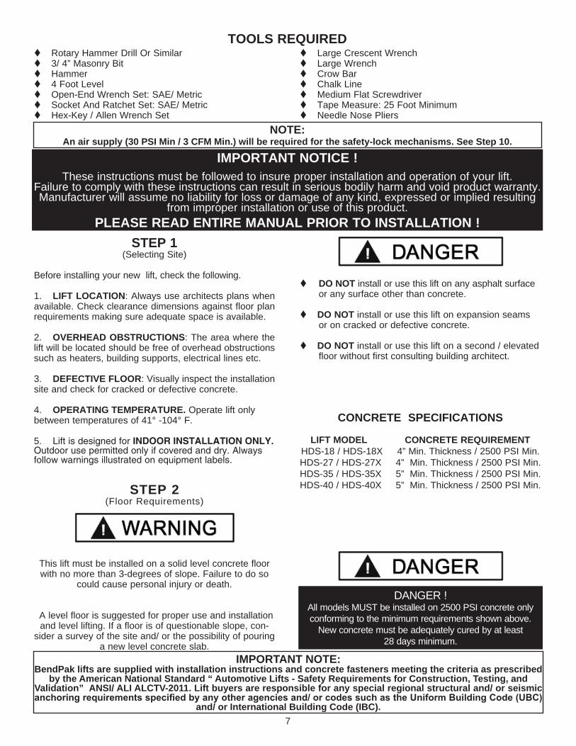
STEP 1(Selecting Site)
Before installing your new lift, check the following.
1. LIFT LOCATION: Always use architects plans when available. Check clearance dimensions against floor plan requirements making sure adequate space is available.
2. OVERHEAD OBSTRUCTIONS: The area where the lift will be located should be free of overhead obstructions such as heaters, building supports, electrical lines etc.
3. DEFECTIVE FLOOR: Visually inspect the installation site and check for cracked or defective concrete.
4. OPERATING TEMPERATURE. Operate lift only between temperatures of 41° -104° F.
5. Lift is designed for INDOOR INSTALLATION ONLY. Outdoor use permitted only if covered and dry. Always follow warnings illustrated on equipment labels.
STEP 2(Floor Requirements)
This lift must be installed on a solid level concrete floor with no more than 3-degrees of slope. Failure to do so
could cause personal injury or death.
A level floor is suggested for proper use and installation and level lifting. If a floor is of questionable slope, con-
sider a survey of the site and/ or the possibility of pouring a new level concrete slab.
t DO NOT install or use this lift on any asphalt surface or any surface other than concrete.
t DO NOT install or use this lift on expansion seams or on cracked or defective concrete.
t DO NOT install or use this lift on a second / elevated floor without first consulting building architect.
CONCRETE SPECIFICATIONS
LIFT MODEL CONCRETE REQUIREMENT HDS-18 / HDS-18X 4” Min. Thickness / 2500 PSI Min.HDS-27 / HDS-27X 4” Min. Thickness / 2500 PSI Min.HDS-35 / HDS-35X 5” Min. Thickness / 2500 PSI Min.HDS-40 / HDS-40X 5” Min. Thickness / 2500 PSI Min.
t Rotary Hammer Drill Or Similar t 3/ 4” Masonry Bit t Hammert 4 Foot Levelt Open-End Wrench Set: SAE/ Metrict Socket And Ratchet Set: SAE/ Metrict Hex-Key / Allen Wrench Set
t Large Crescent Wrencht Large Wrencht Crow Bar t Chalk Linet Medium Flat Screwdrivert Tape Measure: 25 Foot Minimumt Needle Nose Pliers
IMPORTANT NOTICE !These instructions must be followed to insure proper installation and operation of your lift.
Failure to comply with these instructions can result in serious bodily harm and void product warranty. Manufacturer will assume no liability for loss or damage of any kind, expressed or implied resulting
from improper installation or use of this product. PLEASE READ ENTIRE MANUAL PRIOR TO INSTALLATION !
DANGER !All models MUST be installed on 2500 PSI concrete only conforming to the minimum requirements shown above.
New concrete must be adequately cured by at least 28 days minimum.
NOTE: An air supply (30 PSI Min / 3 CFM Min.) will be required for the safety-lock mechanisms. See Step 10.
TOOLS REQUIRED
IMPORTANT NOTE:BendPak lifts are supplied with installation instructions and concrete fasteners meeting the criteria as prescribed
by the American National Standard “ Automotive Lifts - Safety Requirements for Construction, Testing, and Validation” ANSI/ ALI ALCTV-2011. Lift buyers are responsible for any special regional structural and/ or seismic anchoring requirements specified by any other agencies and/ or codes such as the Uniform Building Code (UBC)
and/ or International Building Code (IBC).

8
When removing the lift from shipping angles pay close attention as the posts can slide and can cause injury. Prior to removing the bolts make sure the posts are held securely by a fork lift or some other heavy lifting device.
Rear Crosstube
Powerside Runway
Column with Power Unit Mounting Bracket
Small Window(2 Pulleys)
Front Crosstube
Offside Runway
Approach Ramps
Large Window(4 Pulleys)
Assembly View HDS-18/ 27/ 35/ 40

9
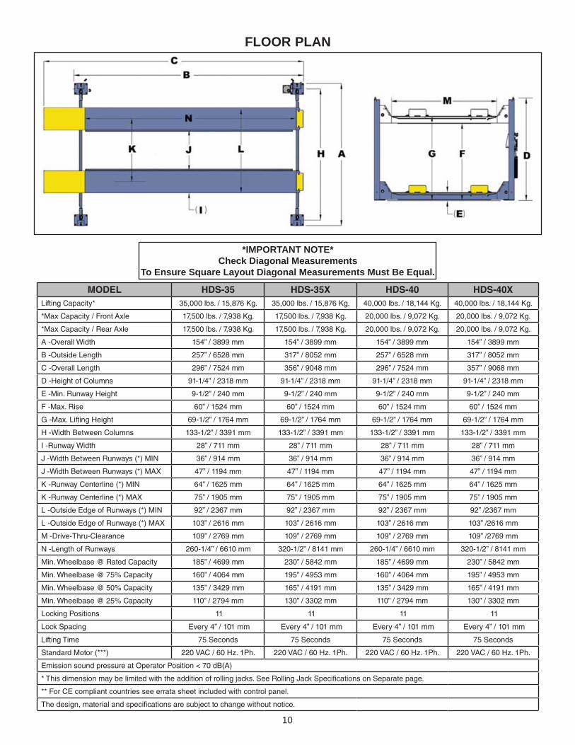
FLOOR PLAN
*IMPORTANT NOTE*Check Diagonal Measurements
To Ensure Square Layout Diagonal Measurements Must Be Equal. MODEL HDS-18 HDS-18X HDS-27 HDS-27X
Lifting Capacity* 18,000 lbs. / 8165 Kg. 18,000 lbs./ 8165 Kg. 27,000 lbs. / 12,247 Kg. 27,000 lbs. / 12,247 Kg.
*Max Capacity / Front Axle 9,000 lbs. / 4082 Kg. 9,000 lbs. / 4082 Kg. 13,500 lbs. / 6,124 Kg. 13,500 lbs. / 6,124 Kg.
*Max Capacity / Rear Axle 9,000 lbs. / 4082 Kg. 9,000 lbs. / 4082 Kg. 13,500 lbs. / 6,124 Kg. 13,500 lbs. / 6,124 Kg.
A -Overall Width 153-1/2” / 3899 mm. 153-1/2” / 3899 mm. 153-1/2” / 3899 mm. 153-1/2” / 3899 mm.
B -Outside Length 201” / 5105 mm 317” / 8052 mm 257” / 6528 mm 317” / 8052 mm
C -Overall Length 246-1/2” / 6260 mm 362-1/4” / 9204mm 296-1/4” / 7524 mm 356-1/4” / 9048 mm
D -Height of Columns 91-1/4” / 2318 mm 91-1/4” / 2318 mm 91-1/4” / 2318 mm 91-1/4” / 2318 mm
E -Min. Runway Height 8-1/2” / 216 mm 8-1/2” / 216 mm 9-1/2” / 240 mm 9-1/2” / 240 mm
F -Max. Rise 60” / 1524 mm 60” / 1524 mm 60” / 1524 mm 60” / 1524 mm
G -Max. Lifting Height 68-1/2” / 1740 mm 68-1/2” / 1740 mm 69-1/2” / 1764 mm 69-1/2” / 1764 mm
H -Width Between Columns 133-1/2” / 3391 mm 133-1/2” / 3391 mm 133-1/2” / 3391 mm 133-1/2” / 3391 mm
I -Runway Width 22” / 559 mm 22” / 559 mm 22” / 559 mm 22” / 559 mm
J -Width Between Runways (*) MIN 38-1/2” / 980 mm 38-1/2” / 980 mm 38-1/2” / 980 mm 38-1/2” / 980 mm
J -Width Between Runways (*) MAX 56” / 1422 mm 56” / 1422 mm 56” / 1422 mm 56” / 1422 mm
K -Runway Centerline (*) MIN 60” / 1524 mm 60” / 1524 mm 60” / 1524 mm 60” / 1524 mm
K -Runway Centerline (*) MAX 78” / 1981 mm 78” / 1981 mm 78” / 1981 mm 78” / 1981 mm
L -Outside Edge of Runways (*) MIN 82” / 2083 mm 82” / 2083 mm 82” / 2083 mm 82” / 2083 mm
L -Outside Edge of Runways (*) MAX 100” / 2540 mm 100” / 2540 mm 100” / 2540 mm 100” / 2540 mm
M -Drive-Thru-Clearance 109” / 2769 mm 109” / 2769 mm 109” / 2769 mm 109” / 2769 mm
N -Length of Runways 201” / 5106 mm 318-3/4” / 8098 mm 256-1/2” / 6520 mm 318-3/4” / 8098 mm
Min. Wheelbase @ Rated Capacity 145” / 3683 mm 230” / 5842 mm 185” / 4699 mm 230” / 5842 mm
Min. Wheelbase @ 75% Capacity 125” / 3175 mm 195” / 4953 mm 160” / 4064 mm 195” / 4953 mm
Min. Wheelbase @ 50% Capacity 105” / 2667 mm 165” / 4191 mm 135” / 3429 mm 165” / 4191 mm
Min. Wheelbase @ 25% Capacity 85” / 2159 mm 130” / 3302 mm 110” / 2794 mm 130” / 3302 mm
Locking Positions 11 11 11 11
Lock Spacing Every 4” / 101 mm Every 4” / 101 mm Every 4” / 101 mm Every 4” / 101 mm
Lifting Time 75 Seconds 75 Seconds 75 Seconds 75 Seconds
Standard Motor (**) 220 VAC / 60 Hz. 1Ph. 220 VAC / 60 Hz. 1Ph. 220 VAC / 60 Hz. 1Ph. 220 VAC / 60 Hz. 1Ph.
Emission sound pressure at Operator Position < 70 dB(A)
* This dimension may be limited with the addition of rolling jacks. See Rolling Jack Specifications on Separate page.
** For CE compliant countries see errata sheet included with control panel.
The design, material and specifications are subject to change without notice.
10
FLOOR PLAN
MODEL HDS-35 HDS-35X HDS-40 HDS-40X Lifting Capacity* 35,000 lbs. / 15,876 Kg. 35,000 lbs. / 15,876 Kg. 40,000 lbs. / 18,144 Kg. 40,000 lbs. / 18,144 Kg.
*Max Capacity / Front Axle 17,500 lbs. / 7,938 Kg. 17,500 lbs. / 7,938 Kg. 20,000 lbs. / 9,072 Kg. 20,000 lbs. / 9,072 Kg.
*Max Capacity / Rear Axle 17,500 lbs. / 7,938 Kg. 17,500 lbs. / 7,938 Kg. 20,000 lbs. / 9,072 Kg. 20,000 lbs. / 9,072 Kg.
A -Overall Width 154” / 3899 mm 154” / 3899 mm 154” / 3899 mm 154” / 3899 mm
B -Outside Length 257” / 6528 mm 317” / 8052 mm 257” / 6528 mm 317” / 8052 mm
C -Overall Length 296” / 7524 mm 356” / 9048 mm 296” / 7524 mm 357” / 9068 mm
D -Height of Columns 91-1/4” / 2318 mm 91-1/4” / 2318 mm 91-1/4” / 2318 mm 91-1/4” / 2318 mm
E -Min. Runway Height 9-1/2” / 240 mm 9-1/2” / 240 mm 9-1/2” / 240 mm 9-1/2” / 240 mm
F -Max. Rise 60” / 1524 mm 60” / 1524 mm 60” / 1524 mm 60” / 1524 mm
G -Max. Lifting Height 69-1/2” / 1764 mm 69-1/2” / 1764 mm 69-1/2” / 1764 mm 69-1/2” / 1764 mm
H -Width Between Columns 133-1/2” / 3391 mm 133-1/2” / 3391 mm 133-1/2” / 3391 mm 133-1/2” / 3391 mm
I -Runway Width 28” / 711 mm 28” / 711 mm 28” / 711 mm 28” / 711 mm
J -Width Between Runways (*) MIN 36” / 914 mm 36” / 914 mm 36” / 914 mm 36” / 914 mm
J -Width Between Runways (*) MAX 47” / 1194 mm 47” / 1194 mm 47” / 1194 mm 47” / 1194 mm
K -Runway Centerline (*) MIN 64” / 1625 mm 64” / 1625 mm 64” / 1625 mm 64” / 1625 mm
K -Runway Centerline (*) MAX 75” / 1905 mm 75” / 1905 mm 75” / 1905 mm 75” / 1905 mm
L -Outside Edge of Runways (*) MIN 92” / 2367 mm 92” / 2367 mm 92” / 2367 mm 92” /2367 mm
L -Outside Edge of Runways (*) MAX 103” / 2616 mm 103” / 2616 mm 103” / 2616 mm 103” /2616 mm
M -Drive-Thru-Clearance 109” / 2769 mm 109” / 2769 mm 109” / 2769 mm 109” /2769 mm
N -Length of Runways 260-1/4” / 6610 mm 320-1/2” / 8141 mm 260-1/4” / 6610 mm 320-1/2” / 8141 mm
Min. Wheelbase @ Rated Capacity 185” / 4699 mm 230” / 5842 mm 185” / 4699 mm 230” / 5842 mm
Min. Wheelbase @ 75% Capacity 160” / 4064 mm 195” / 4953 mm 160” / 4064 mm 195” / 4953 mm
Min. Wheelbase @ 50% Capacity 135” / 3429 mm 165” / 4191 mm 135” / 3429 mm 165” / 4191 mm
Min. Wheelbase @ 25% Capacity 110” / 2794 mm 130” / 3302 mm 110” / 2794 mm 130” / 3302 mm
Locking Positions 11 11 11 11
Lock Spacing Every 4” / 101 mm Every 4” / 101 mm Every 4” / 101 mm Every 4” / 101 mm
Lifting Time 75 Seconds 75 Seconds 75 Seconds 75 Seconds
Standard Motor (***) 220 VAC / 60 Hz. 1Ph. 220 VAC / 60 Hz. 1Ph. 220 VAC / 60 Hz. 1Ph. 220 VAC / 60 Hz. 1Ph.
Emission sound pressure at Operator Position < 70 dB(A)
* This dimension may be limited with the addition of rolling jacks. See Rolling Jack Specifications on Separate page.
** For CE compliant countries see errata sheet included with control panel.
The design, material and specifications are subject to change without notice.
*IMPORTANT NOTE*Check Diagonal Measurements
To Ensure Square Layout Diagonal Measurements Must Be Equal.

11
CLEARANCESHDS SUPER DUTY
1. Lift Location: Use architects plan and Engineers automatic level (transit) when available to locate lift. The above shows clearances of a typical bay layout. Lift floor area should be level.
2. Ceiling or overhead clearance must be 80” plus height of tallest vehicle.
3. Estimating Column Shim requirements:In the following section, the terms “highest” and “lowest” refer to elevation of floor.
A. Mark locations where lift columns will be posi-tioned in bay.
B. Place target on floor at column positions (NOT on column base plates) and record readings.
C. Find the highest of the four locations. Find the difference between the readings at each of the re-
maining three columns and the highest reading.
D. The difference is the estimated amount of shim thickness needed at each column.
Note: Maximum shim thickness is 1/2” per column using shims and anchors provided with lift.
If no transit is available, floor slope can be determined by using a chalk line and level.
24in610mm
MINIMUM TONEAREST WALL
54in1372mm
MINIMUM TONEAREST BAY
OR OBSTRUCTION
APPROACH

12
IMPORTANT NOTE !The power unit can be located at either “ X” location shown below. It is important to locate the POWERSIDE runway (with cylinder) on the SAME SIDE as the power unit location. Utility rails on the side of each runway MUST be installed facing the center. For the remainder of this instruction the power unit will be illustrated mounted at the DRIVER-SIDE (LEFT) FRONT column - TOP ILLUSTRATION. For power unit at right rear, rotate lift 180° leaving approach ramps and front tire stops in original position.
POWER UNIT LOCATION

STEP 3(Column & Cross Tube Installation)
1. Place a chalk line on the floor according to the floor planlayout. Pay attention to the Power Unit location. Locate andstand the Columns at their respective locations. DO NOTBOLT Columns down at this time. Use caution to prevent the Columns from falling over. (See Fig. 3.1)
2. To estimate the shim requirements, place a target on floor at each Column position and record the readings. Find the highest of the four locations then find the differ-ence between each of the remaining Columns. This differ-ence is the estimated amount of shim thickness that will be required at each Column. (See Fig. 3.2)
Note: The maximum shim thickness recommended by the factory is no more than 1/2” per Column using shims and anchors provided with the lift. A maximum shim thickness of 2” is possible by ordering optional Shim Plates. Contact your
authorized BendPak Distributor for ordering information.
3. Using a forklift or crane, raise the Cross Tubes (making sure the Plastic Slide Blocks are still in position) and drop down into the top of the Columns. NOTE: The sheave windows should be positioned inward and adjacent the Power unit Column. (See Fig. 3.3)
4. With the Columns standing and the Cross Tubes inposition, install the Safety Ladders. Pass the Laddersthrough the Column openings and drop down through theSlide Block guide slots on the cross tube until the Ladderscome to rest on the Base Plates. DO NOT BOLT Columnsdown at this time. (See Fig. 3.4 - 3.5)
13
Fig. 3.1
Fig. 3.3
Fig. 3.4
Fig. 3.5
Fig 3.2

5. The Columns and Cross Tubes will now be in position and spaced properly for the runways.
6. Install the column TOP CAPS using the M16 X 2 Hex Bolts, nuts & washers. Install the nut on each Safety Ladder until 1/2” of threads are exposed and the Ladder is raised at least 1/2” off of the base of the Column.NOTE: Raise the Ladder at least 1/2” off of the base of the column or damage to the lift will occur. Be sure to position the Cable hole INWARD. (See Fig. 3.6 - 3.7)
STEP 4(Raising The Cross Tubes)
1. Before proceeding it will be necessary to first raise the Cross Tubes off the ground to facilitate Cable routing and final assembly.
2. Manually raise the Cross Tubes until the Primary Safety Locks engage and rest on the lock position second down from the top of the Ladder or approximately 66” off the ground. It is important that the SLACK SAFETY LOCK IS CLEARED. The Slack Safety Lock must never rest on the Safety Ladder. (See Fig. 4.1 -4.3)
3. The Columns and Cross Tubes will now be in position and spaced properly for the Runways. Be very careful not to disturb the Columns and Cross Tubes at this time as they may tip over causing personal injury or harm. (See Fig. 4.4)
14
DANGER !Be careful not to disturb the Columns and Cross Tubes as they may tip over causing personal injury or harm.
IMPORTANT NOTE !It is important that the SLACK SAFETY LOCK IS
CLEARED. The slack safety lock must never rest on the safety ladder.
Fig 3.6
Fig 3.7
Fig 4.1
Fig 4.2
Fig 4.3
Fig 4.4

STEP 5(Powerside Runway Installation)
1. Locate the POWERSIDE RUNWAY, easily identified by the Cylinder and Sheave roller mounting structures welded on the underside. The Powerside Runway will be positioned on the side of the lift where the Power Unit is installed. (See Fig. 5.1)
2. Install the Cylinder and Cable Block as shown. Ensure the snap ring is installed on the cylinder rod. (See Fig. 5.2 - 5.3)
3. Remove any pre-installed CABLE SHEAVES and SPACERS from the POWERSIDE RUNWAY making sure to and pay attention to the order in which they are removed. (This will help at the time of re-installation.) First remove the Retaining Pin then press the Sheave Axle through the Runway completely until the Sheaves and Spacers are removed. (See Fig. 5 4)
4. Position the POWERSIDE RUNWAY on top of the Cross Tubes with the UTILITY RAIL towards the center. The fitting holes located at the side of the Powerside Runway should be adjacent the POWER UNIT COLUMN. Align the holes in the Runway with the holes on the Cross Tubes and bolt together using four M18 x 2.5 hex bolts and washers. (See Fig. 5.5)
STEP 6(Offside Runway Installation)
1. Position the OFFSIDE RUNWAY on top of the Cross Tubes with the UTILITY RAIL located inside.(See Fig. 6.1)
STEP 7(Sheave Installation)
15
DANGER !DO NOT PROCEED with Cable installation or go near the
lift work area unless visual confirmation is made of ALL Safety Locks. ALL locks MUST be engaged before proceed-ing. Failure to comply with these instructions may result in
severe personal injury or death. (See page 26.)Fig. 5.4
Fig. 5.5
Fig. 6.1
Fig. 5.2
Cable Block
Cable BlockCable Retainer
Cylinder Guide
Thread nut until snap ring can be installed.
Utility Rail
Cylinder
Fig. 5.3
Fig. 5.1

1. Inspect cables to insure proper lengths. All CABLES should have ID tags showing proper Cable lengths.
2. In order to install the Cables it is necessary to first extend the HYDRAULIC CYLINDER. Remove both Cylinder port plugs then use an air gun or come-along to extend the Cylinder. IMPORTANT! - Be careful not to damage the chrome rod during this step. (See Fig. 7.1)
3. You must reinstall the SHEAVES, SPACERS AND PINS in the same order as they are removed. Note: Failure to install PLASTIC FRICTION SPACERS will result in premature sheave wear and void warranty. (See Fig. 7.2 & 7.3.)
HELPFUL TIPInstall the Sheaves and Cables in the order as shown below
starting from the SHORTEST (A) to the LONGEST (D).
16
Sheave Pin
Sheave Pin
Fig. 7.1
Fig. 7.2
Fig. 7.3
Fig. 7.4
WARNING!WHEN THE CABLE ADJUSTING NUTS BOTTOM OUT ON THE THREADED END OF THE CABLE
CONNECTOR AND THERE IS STILL SLACK IN THE CABLES, THE CABLES HAVE STRETCHED BEYOND THE SAFE USEFUL LENGTH AND NEED TO BE REPLACED WITH FACTORY APPROVED CABLE ASSEMBLIES.
DO NOT PLACE WASHERS, SPACERS OR OTHER DEVICES TO “ SHORTEN” THE EFFECTIVE CABLE LENGTH AS DAMAGE TO THE LIFT OR INJURY TO PERSONS MAY OCCUR.

4. With the CABLES properly routed, hold the Sheaves in position and install the SHEAVE PIN. (See Fig. 7.5)
5. Repeat the same procedure at the other end of the lift starting with the bottom Sheave and Cable first. Be sure that you install the Sheaves, Spacers and Pins in the same order as they are removed.
6. Install the Sheave Pin Retaining Pin and Hair Pins though the bottom of the Sheave Pin. (See Fig. 7.6)
17
DANGER !DO NOT PROCEED unless visual confirmation is made
of ALL Safety Locks. ALL locks MUST be engaged before proceeding. Failure to comply with these instructions may result in severe personal injury or death. (See page 25.)
Fig. 7.6
SheavePin
Stack Cables and Sheavesin proper order and make ready for the Sheave Pin.
Fig. 7.5

7. Each cable must be installed through the CABLE RETAINER first to keep Cables stowed in their proper position on the Cable Block. (See Fig. 7.7)
8. Route the Cable ends through the ends of each Cross Tube, over the SLACK SAFETY SHEAVE then to the top of each column. Secure using the M30 Hex Nuts and Flat Washers. Tighten each nut until there is at least one inch of threads protruding through the top of the nut. The Cables will remain loose until start up and final Cable adjustments are made. (See Fig. 7.8 & 7.9)
9. After routing the Cables double-check to make sure all are properly positioned and REMAIN WITHIN THE GROOVES of ALL Sheaves. (See Fig. 7.10. & 7.11)
18
DANGER !Failure to route Lifting Cables as described may lead to serious personal injury and/ or death to operator or
bystander and/ or may cause damage to property.
DANGER!Lifting Cables routed through the Cross Tubes must run BELOW the Cross Tube Mounting Bolts. Serious damages or injury can occur if Cables are not routed
correctly. (See Fig 7.12)
Fig. 7.7
Fig. 7.8
Fig. 7.10
Fig. 7.11
Fig. 7.12
Fig. 7.9Install each nut until 1” MIN of threads are exposed
Lifting Cable
Cable Block
Cable Retainer
Cable Plug End
Cylinder Guide
Thread nut until snap ring can be installed.

19
STEP 8(Power Unit Installation)
1. Mount the POWER UNIT to the Mounting Bracket using the M10 Hex Bolts and Nylock nuts then FILL THE RES-ERVOIR with 20-quarts of 10-WT hydraulic oil or Dexron automatic transmission fluid. (See Fig. 8.1)
STEP 9(Routing Hydraulic Hoses)
1. Install the 90-degree Hydraulic Fitting to the POWER PORT and the 90° Air Line Compression Fitting to the RETURN PORT of the Power Unit and connect the Hoses as described below. It will be necessary to remove the ship-ping plugs from both ports prior to installing the Fittings. On the pipe thread side of the fitting it is recommended to use Teflon tape or pipe sealer. DO NOT USE TEFLON TAPE on the JIC flared end. It will be necessary to remove the ship-ping plugs from both ports prior to installing the fittings. (See Fig. 9.1 -9.2
2. Remove the captive nut on the Compression Fitting. Insert the Plastic Air line through the alignment sleeve and into the end of the fitting until it bottoms out. Then tighten the nut on the fitting. (See Fig 9.3)
DANGER !ALL WIRING MUST BE PERFORMED
BY A LICENSED ELECTRICIAN.
NOTE:POWER AND RETURN PORT LOCATIONS MAY VARY. CONFIRM POWER AND RETURN PORT
LOCATIONS IN POWER UNIT DOCUMENTATION OR CONTACT TECHNICAL SUPPORT.
DANGER!
DO NOT PERFORM ANY MAINTENANCE OR INSTALLATION OF ANY COMPONENTS WITH OUT FIRST ENSURING THAT ELECTRICAL POWER HAS
BEEN DISCONNECTED AT THE SOURCE OR PANEL AND CANNOT BE RE-ENERGIZED UNTIL ALL
MAINTENANCE AND/ OR INSTALLATION PROCEDURES ARE COMPLETED.
Fig. 9.1
Fig. 9.2
Fig. 8.1
90° Air Line Compression
Fitting
90° O-Ring Fitting
Power Port
Return Port
Remove Shipping Plugs
Install Fittings

20
3. Install the 90° Hydraulic Fittings in the port at the ram end of the cylinder. On the pipe thread side of the fitting it is recommended to use Teflon tape or pipe sealer. DO NOT USE TEFLON TAPE on the JIC flared end. (See Fig. 9.4 )
4. Install the 90° Air Line Compression Fitting in the port at the base, pinned end of the Cylinder. On the pipe thread side of the Fitting, it is recommended to use Teflon Tape or pipe sealer. (See Fig. 9.5)
5. Route both the Power Unit Hydraulic Hose and TWO (2) lengths of Air Line through the Flex Hose. (See Fig. 9.6)
6. Install the end of Flex Hose with the Straight Fitting on the Hydraulic Hose into the hole in the Powerside Runway adjacent to the Power Unit. Install the end of the Flex Hose with the 90° Fitting on the Hydraulic Hose in the Flex Hose Bracket Assy. Tighten the plastic nuts securely. (See Fig 9.7)
7. Connect the hydraulic hose and air line as shown below making sure the hydraulic hose passes through the retaining rings. MAKE SURE HOSES ARE KEPT CLEAR OF CABLES. There will be one air line hose left uncon-nected in this step. This air line will be used to activate the pneumatic safety locks in the next step. See Fig 9.3 for Compression Fitting instructions. (See Fig. 9.8)
8. Connect the 90° end of the Power Unit Hydraulic Line to the 90° Power Unit Fitting. Connect the Return Air Line to the 90° Air Line Compression Fitting. There will be one air line hose left unconnected at this time. This air line hose will be used to activate the pneumatic safety locks on the next page. (See Fig. 9.9)
Fig. 9.5
Fig. 9.4
90° Air Line Compression
Fitting
90° Hydraulic Fitting
Fig. 9.3
Flex Hose
Power HoseAir Line Hose
90° Hose End
Fig. 9.6
Retaining Ring
Retaining Ring
Straight Hose End
Fig. 9.7
Fig. 9.8
Fig. 9.9

21
STEP 10( Routing Air Lines)
1. Mount the Push Button Air Valve Assembly on to the power unit mounting bracket. The Push Button Air Valve should be positioned away from the Power Side Ramp on the “out” side of the lift for operator safety. (See Fig 10.1)
2. Route the air line that was left unconnected in Step 10 to the 90° Air Line Compression Fitting of the Push Button Air Valve Assembly. (See Fig 10.2)
3. Once the air line has been connected with the Push Button Air Valve, cut the air lines to length by following the Safety Air Line Routing diagram located on Page 22 and connect female branch “tee” fittings where needed.
Fig. 10.1
Air Supply In
Fig. 10.2
NOTE:A FILTER/REGULATOR/LUBRICATOR MUST BE
INSTALLED ON AIR SUPPLY AT LIFT. FAILURE TO DO SO WILL VOID THE WARRANTY.
NOTE:MAKE SURE THE PUSH BUTTON AIR VALVE
PORT MARKED “INLET” IS FACING TOWARDS THE SOURCE OF COMPRESSED AIR.
Push Button Air Valve Assembly
To Flex Hose

22
Male Branch “Tee” Fitting
Male Branch “Tee” Fitting
Route Airlines Though Retainers
Underneath Runway
SAFETY AIR LINE ROUTINGNOTE:
CUT THE PROVIDED 1/4” AIR LINE TUBING WITH A SHARP BLADE TO LENGTHS AS REQUIRED. TUBING MUST BE CUT SQUARE WITH ALL PLASTIC BURRS REMOVED.
AIR TUBING ASSEMBLY:SEE PAGE 20 FOR ASSEMBLY OF AIR LINE TUBING INTO FITTING.
CAUTION:REMOVING THE AIR TUBING FROM THE COMPRESSION FITTINGS WILL CAUSE DAMAGE TO THE TUBING
ITSELF. USE OF A DAMAGED AIR LINE MAY RESULT IN SAFETY LOCK FAILURE.
NOTE: FEED AIR LINE TUBING THROUGH THE RETAINER TUBING ON THE OUTSIDE OF THE CROSSTUBES

23
All wiring must be performed by a certified electrician only.
DANGER!
DO NOT PERFORM ANY MAINTENANCE OR INSTALLATION OF ANY COMPONENTS WITH OUT FIRST ENSURING THAT ELECTRICAL POWER HAS
BEEN DISCONNECTED AT THE SOURCE OR PANEL AND CANNOT BE RE-ENERGIZED UNTIL ALL
MAINTENANCE AND/OR INSTALLATION PROCEDURES ARE COMPLETED.
SEE WIRING INSTRUCTIONS AFFIXED TO MOTOR FOR PROPER WIRING INSTRUCTIONS.
Identify which Power Unit the lift was shipped with by looking on the data tag affixed to the Power Unit motor head. if the model number begins with the letter “S” then use the “S” wiring diagrams. If the model number begins with the letter “E” or “F” then use the “E” or “F” wiring diagrams.
IMPORTANT POWER-UNIT INSTALLATION NOTES
n DO NOT run power unit with no oil. Damage to pump can occur.n The power unit must be kept dry. Damage to power unit caused by water or other liquids such as detergents, acid etc., is not covered under warranty.n Improper electrical hook-up can damage motor and will not be covered under warranty.n Motor can not run on 50HZ without a physical change in motor.n Use a separate breaker for each power unit.n Protect each circuit with time delay fuse or circuit breaker.n For 208-230 volt, single phase, use a 25 amp fuse.n For 208-230 volt, three phase, use a 20 amp fuse.n For 380-440 volt, three phase, use a 15 amp fuse.
Installation and adjustment. DO NOT attempt to raise vehicle until a thorough operation check has been completed.

24

25
STEP 11(Power Unit Hook Up)
1. Have a CERTIFIED ELECTRICIAN run the power supply to motor. Refer to the data plate found on the motor for proper power supply and wire size.
RISK OF EXPLOSION!This equipment has internal arcing or PARTS THAT MAY SPARK and should not be exposed to flammable vapors. Motor should not be located in a recessed area or below floor level. NEVER expose motor to rain or other damp
environments. DAMAGE TO MOTOR CAUSED BY WATER IS NOT COVERED UNDER WARRANTY.
STEP 12(Installing The Slack Safety Springs)
The following steps involve the SLACK CABLE SAFETY DEVICE and MAIN SAFETY. Failure to follow these
steps could result in serious injury or death in the event of cable failure.
1. Install the unattached end of the ALL SAFETY LOCK SPRINGS as shown. Make sure the spring ends are secure at both ends. DO NOT ATTEMPT TO RAISE THE LIFT UNTIL THE SLACK SAFETY SPRINGS ARE ATTACHED AND THE ROLLERS ARE PULLED CLEAR FROM THE LADDER. (See Fig. 12.1)
2. Repeat this step for each corner of the lift.
STEP 13(Lift Start Up / Final Adjustments)
1. Make sure the POWER UNIT RESERVOIR is full with 20-quarts of 10-WT hydraulic oil or Dexron automatic transmission fluid.
2. Spray the inside of the Columns where the Slide Blocks glide with a light lubricant or WD-40.
3. Test the Power Unit by pressing the push-button switch. If the motor sounds like it is operating properly, raise the lift and check all hose connections for leaks. If the motor gets hot or sounds peculiar, stop and check all electrical connections.
4. Before proceeding, double-check to make sure all Cables are properly positioned within the grooves of ALL sheaves. Make sure all cable sheave retaining pins and/ or clips are secure.
I IMPORTANT NOTE:CAUTION Never operate the motor on line voltage
less than 208V. Motor damage may occur which is not covered under warranty. Have a certified electrician run appropriate power supply to motor. Size wire for 25 amp
circuit. See Motor Operating Data Table.IMPORTANT: Use separate circuit for each power unit.Protect each circuit with time delay fuse or circuit break-
er. For single phase 208-230V, use 25 amp fuse.Three phase 208-240V, use 25 amp fuse. For three phase 400V and above, use 15 amp fuse. All wiring must comply with NEC and all local electrical codes.
Fig. 11.1
Typical Power Unit shown, controls and labels may vary.
Fig 12.1
Make sure the ends of all three (3) springs are securely attached to the Safety Locks
and Cross Cube anchor points.

26
5. Check to make sure that all Slack Safety locks are cleared and free. (See Fig. 13.1)
6. Continue pressing the raise button until the Cables get taught and the lift starts to move.
7. Raise lift until the lift stops and lower until the Safeties engage the Top Locking Position. Adjust each ladder so that each Safety Lock rests on the corresponding Top Lock Position. Then adjust each Cable Nut so that each Safety Lock is ONE INCH (1”) above the Top Lock Position. The Cable Nuts MUST be tightened until there is at least one inch of threads protruding through the nut. (See Fig. 13.2)Failure to do so could result in serious injury or death.
All cable nuts MUST be tightened on each end until there is at least one inch of threads protruding through the nut.
Failure to do so could result in serious injury or death.
NOTE:There will be initial stretching of the cables in the beginning and/ or with increased loads. Adjust the
cables as outlined above a week after first use, then every three to six months thereafter depending on usage
and/ or to compensate for stretch.
8. After connecting the air supply, press the PUSH BUTTON AIR VALVE and check that all Safety Locks are functioning properly. Lower the lift by pressing the push but-ton air valve and Power Unit lowering valve simultaneously.
KEEP HANDS AND FEET CLEAR. Remove hands and feet from any moving parts. Keep feet clear of lift when
lowering. Avoid pinch points.
9. Check all MAIN SAFETY LOCKS to make sure they move freely and spring back to the lock position when released. Lubricate all SAFETY PIVOT points with WD-40 or equal.
10. Run the lift up and down a few times to insure that the locks are engaging uniformly and that the safety release mechanisms are functioning. Re-adjust if necessary.
STEP 14(Anchoring The Columns)
1. Before proceeding, DOUBLE CHECK MEASURE-MENTS and make certain that the bases of each column are square and aligned with the chalk line. Raise the lift up and down and make sure it operates properly at the locations prescribed by the markings on the floor. (See Fig. 14.1)
2. Using the BASE PLATE on each column as a guide, drill each anchor hole approximately 5” deep using a rotary hammer drill and 3/ 4” concrete bit. (See Fig. 14.2)
Fig. 13.1
Fig. 13.2
Fig. 14.1
Fig. 14.2
IMPORTANT NOTE:BendPak lifts are supplied with installation instruc-tions and concrete fasteners meeting the criteria as prescribed by the American National Standard “ Au-tomotive Lifts - Safety Requirements for Construc-tion, Testing, and Validation” ANSI/ ALI ALCTV-2011. Lift buyers are responsible for any special regional structural and/ or seismic anchoring requirements specified by any other agencies and/ or codes such as the Uniform Building Code (UBC) and/ or Interna-
tional Building Code (IBC).

27
3. After drilling, REMOVE DUST thoroughly from each hole using compressed air and/ or bristle brush. Make certain that the Columns remain aligned with the chalk line.
ALWAYS WEAR SAFETY GOGGLES.
4. Assemble the washers and nuts on the anchors then tap into each hole with a sledge until the washer rests against the base plate. Be sure that if shimming is required, enough THREADS ARE LEFT EXPOSED. (See Fig. 14.3)
5. If shimming is required, insert the shims as necessary under the base plate so that when the anchor bolts are tightened, the columns will be plumb. (See Fig. 14.4)
6. After any necessary shims are installed, tighten each anchor nut 3-5 turns past hand tight. IMPORTANT - If anchor bolts do not hold when torqued to require d amount, concrete must be replaced. Saw cut and remove 24” x 24” square area under each column base then re-pour with reinforced 2500 PSI concrete to a depth of six inches minimum, keying new concrete under existing floor. (See Fig. 14.5)
STEP 15(Final Assembly)
1. Install the approach ramps on the entry side of the lift. (See Fig. 15.1 &15.2)
2. Install the front tire stops at the forward end of the lift using the hex bolts, nuts and washers. (See Fig. 15.3)
STEP 16(Leveling / Synchronizing)
1. Using an engineer’s automatic Level (transit), locate the Level, at a convenient location in the shop that allows an unobstructed view of all four corners of the runways.
2. Follow the Level manufacturer’s instructions for prop-er setup of the Level. Be sure it is ADJUSTED LEVEL in all directions.
3. Raise the lift approximately 30” - 40” . Then lower lift until all locking latches are engaged in each column and the runways are in full down position on locks.
4. Place a Level target on the right/ front corner of the runway. (See Fig. 16.1)
Fig. 14.3
Fig. 14.4
Fig. 14.5
Fig. 15.1
Fig. 15.2
Fig. 15.3

5. Beginning with “ A” position, sight the level to the target and mark the number or the graduation on the inch scale of the target that aligns to the cross hairs of the Level, (See Fig. 16.1)
Note: Use a pencil, marking pen or attach a paper cliponto the target scale at the cross hair reference.
6. Next, move the target and place it at point “ B” on the runway. (See Fig. 16.1)
7. Rotate the Level and focus on the target scale.
8. Adjust the adjustment nut on the safety ladder bar at the top of the Column at “ B” until the cross hair of the Level align to reference mark on the target scale. (See Fig. 16.1)
9. Repeat steps locating the target assembly at points “ C” and “ D” and adjusting safety ladders at each cor-responding Column until the reference mark on the target scale is on the cross hair of the Level. The runways are now level at all four points. (See Fig. 16.1)
10. To complete the leveling procedures, SNUG EACH SAFETY LADDER JAM NUT against the bottom of the Column Top Plate. (See Fig. 16.2)
11. Next, load vehicle such as an RV onto the lift.
12. Raise the lift to full height. Listen and watch as the locking latches click in place. SYNCHRONIZE BY ADJUSTING THE CABLES so that all four latches click at the same time. Make necessary adjustments to the cables allowing COMPENSATION FOR STRETCH.
Safety locks may not click in at exactly the same time when vehicles are being raised. They should be close. Be sure that all four corners have passed the SAME
Safety Ladder Bar slot before lowering lift on the safety locks. NEVER lower lift on different safety lock position
or damage to the lift may result.
STEP 17(Bleeding)
1. Lift must be fully lowered before changing or adding fluid.
2. Raise and lower lift six times. The cylinder is self-bleeding. After bleeding system, fluid level in power unit reservoir may be down. Add more fluid if necessary to raise lift to full height. It is only necessary to add fluid to allow full height raise.
3. To pressure test, run lift to full rise and run motor for approximately 3-seconds after lift stops. This will place pressure on the hydraulic system. Stop and check all fit-tings and hose connections. Tighten or reseal if required.
POST-INSTALLATION CHECK-OFF
n Columns properly shimmed and stable
n Anchor Bolts tightened
n Pivot / Sheave Pins properly attached
n Electric power supply confirmed
n Cables adjusted properly
n Safety Locks functioning properly
n Check for hydraulic leaks
n Oil leveln Lubrication of critical components
n Check for overhead obstructions
n All Screws, Bolts, and Pins securely fastened
n Surrounding area cleann Operation, Maintenance and Safety Manuals on site.n Perform an Operational Test with a typical vehicle
28
Fig. 16.1
Fig. 16.2

OPTIONAL EQUIPMENT INSTALLATION
29
5174010 HD/ HDS-18; 27; 35 AIR LINE KITPart # Description Qty.
5550502 1/ 4 Bulkhead Female Straight 3/ 8 Tube
3
5550503 3/ 8 Tube Male Elbow 90° 1/ 4 NPT 35550504 1/ 4 Male Run Tee 3/ 8 Tube #PST 15570784 Ø3/ 8 x 10ft Long Poly Tube Coil Hose 25570725 Ø10mm Poly Flow Tube 290”
5174011 HD/ HDS-18X; 27X; 35X AIR LINE KITPart # Description Qty.
5550502 1/ 4 Bulkhead Female Straight 3/ 8 Tube
3
5550503 3/ 8 Tube Male Elbow 90° 1/ 4 NPT 35550504 1/ 4 Male Run Tee 3/ 8 Tube #PST 15570784 Ø3/ 8 x 10ft Long Poly Tube Coil Hose 25570725 Ø10mm Poly Flow Tube 340”
Rolling Jack maximum weight capacity for use withHDS-18 or HDS-18X is 9,000 lb (4,082 kg) per unitHDS-27 or HDS-27X is 13,500 lb (6,124 kg) per unitHDS-35 or HDS-35X is 17,500 lb (7,938 kg) per unit

30
OPTIONAL EQUIPMENT INSTALLATION

31
STEP 19(Operation Instructions)
OWNER/EMPLOYER RESPONSIBILITIES
The Owner/Employer:
• Shall ensure that lift operators are qualified and that they are trained in the safe use and operation of the lift using the manufacturer’s operating instructions; ALI/SM01-1, ALI Lifting it Right safety manual; ALI/ST-90 ALI Safety Tips card; ANSI/ALI ALOIM-2000, American National Standard for Automotive Lifts-Safety Requirements for Operation, Inspection and Maintenance; ALI/WL Series, ALI Uniform Warning Label Decals/Placards; and in the case of frame engaging lifts, ALI/LP-GUIDE, Vehicle Lifting Points/Quick Reference Guide for Frame Engaging Lifts.
• Shall establish procedures to periodically inspect the lift in accordance with the lift manufacturer’s instructions or ANSI/ALI ALOIM-2000, American National Standard for Automotive Lifts-Safety Requirements for Operation, Inspection and Maintenance; and The Employer shall ensure that lift inspectors are qualified and that they are adequately trained in the inspection of the lift.
• Shall establish procedures to periodically maintain the lift in accordance with the lift manufacturer’s instructions or ANSI/ALI ALOIM-2000, American National Standard for Automotive Lifts-Safety Requirements for Operation, Inspection and Maintenance; and The Employer shall ensure that lift maintenance personnel are qualified and that they are adequately trained in the maintenance of the lift.• Shall maintain the periodic inspection and maintenance records recommended by the manufacturer or ANSI/ALI ALOIM-2000, American National Standard for Automotive Lifts-Safety Requirements for Operation, Inspection and Maintenance.
• Shall display the lift manufacturer’s operating instructions; ALI/SM 93-1, ALI Lifting It Right safety manual; ALI/ST-90 ALI Safety Tips card; ANSI/ALI AL-OIM-2000, American National Standard for Automotive Lifts-Safety Requirements for Operation, Inspection and Maintenance; and in the case of frame engaging lifts, ALI/LP-GUIDE, Vehicle Lifting Points/Quick Reference Guide for Frame Engaging Lifts; in a conspicuous location in the lift area convenient to the operator.
• Shall provide necessary lockout/tagout means for energy sources per ANSI Z244.1-1982 (R1993), Safety Require-ments for the Lockout/Tagout of Energy Sources, before beginning any lift repairs.
• Shall not modify the lift in any manner without the prior written consent of the manufacturer.
STEP 20(Lift Operation Safety)
• DAILY inspect your lift. Never operate if it malfunctions or if it has broken or damaged parts. Use only qualified lift service personnel and genuine BendPak parts to make repairs.
• THOROUGHLY train all employees in use and care of lift, using manufacturer’s instructions and “Lifting It Right” and “Safety Tips” supplied with the lift.
• NEVER allow unauthorized or untrained persons to position vehicle or operate lift.
• PROHIBIT unauthorized persons from being in shop area while lift is in use.
• DO NOT permit anyone on lift or inside vehicle when it is either being raised or lowered.
WARNING!TO AVOID PERSONAL INJURY AND/OR PROPERTY DAMAGE, PERMIT ONLY TRAINED PERSONNEL TO
OPERATE LIFT. AFTER REVIEWING THESE INSTRUC-TIONS, PRACTICE USING LIFT CONTROLS BY
RUNNING THE LIFT THROUGH A FEW UNLOADED CYCLES BEFORE LOADING VEHICLE ON LIFT. NEVER RAISE JUST ONE END, ONE CORNER, OR ONE SIDE
OF VEHICLE.

32
• ALWAYS keep area around lift free of tools, debris, grease and oil.
• NEVER overload lift. Capacity of lift is shown on nameplate affixed to the lift.
• DO NOT stand in front of the vehicle while it is being positioned in lift bay.
• DO NOT block open or override self-closing lift controls; they are designed to return to the “Off” or Neutral position when released.
• ALWAYS remain clear of lift when raising or lowering vehicles.
• ALWAYS use safety stands when removing or installing heavy components.
• DO NOT go under raised vehicle if safety locks are not engaged.
• NEVER LEAVE LIFT IN ELEVATED CONDITION unless all Safety Locks are engaged.
• AVOID excessive rocking of vehicle while on lift.
• ALWAYS CLEAR AREA if vehicle is in danger of falling.
• ALWAYS REMOVE tool trays, stands, etc. before lower-ing lift.
• ALWAYS RELEASE safety locks before attempting to lower lift.
• DO NOT position yourself between a wall and the lift. If the vehicle falls in that direction, you may be severely injured or killed.
To Raise Lift;1. Position vehicle tires in the center of each Runway.
2. Set parking brake and use Wheel Chocks to hold vehicle in position.
3. Before raising vehicle, be sure all personnel are clear of the lift and surrounding area. Pay careful attention to overhead clearances.
4. Raise the lift to the desired height by pressing the push button on the power unit.
5. After vehicle is raised to the desired height, lower thelift onto the nearest Safety Lock. Do not allow Cables tobecome slack. ALWAYS ENSURE ALL SAFETY LOCKS ARE ENGAGED before entering work area.
To Lower Lift;1. Before lowering vehicle, be sure all personnel are clear of the lift and surrounding area. Pay careful atten-tion to overhead clearances. Ensure all tools and equip-ment have been cleared from under the lift.
2. Raise the lift off of the Safety Locks by pressing the push button on the Power Unit. Make sure you raise the lift by at least two inches to allow adequate clearance for the locks to clear.
NOTE: ALLOW (2) SECONDS BETWEEN MOTOR STARTS.
FAILURE TO COMPLY MAY CAUSE MOTOR BURNOUT.
DANGER! VISUALLY CONFIRM THAT ALL PRIMARY SAFETY LOCKS ARE ENGAGED BEFORE ENTERING WORK
AREA. SUSPENSION COMPONENTS USED ON THIS LIFT ARE INTENDED TO RAISE AND LOWER
LIFT ONLY AND ARE NOT MEANT TO BE LOAD HOLDING DEVICES. REMAIN CLEAR OF ELEVATED
LIFT UNLESS VISUAL CONFIRMATION IS MADE THAT ALL PRIMARY SAFETY LOCKS ARE FULLY
ENGAGED AND THE LIFT IS LOWERED ONTO THE SAFETY LOCKS, REFER TO INSTALLATION/
OPERATION MANUAL FOR PROPER SAFETY LOCK PROCEDURES AND/OR FURTHER INSTRUCTION.
WARNING!WHEN LOWERING THE LIFT PAY CAREFUL ATTEN-TION THAT ALL PERSONNEL AND OBJECTS ARE KEPT CLEAR. ALWAYS KEEP A VISUAL LINE OF
SIGHT ON THE LIFT AT ALL TIMES. ALWAYS MAKE SURE THAT ALL LOCKS ARE DISENGAGED. IF ONE
OF THE LOCKS INADVERTENTLY LOCKS UPON DESCENT THE VEHICLE MAY DISMOUNT CAUSING
PERSONAL INJURY OR DEATH.
LIFT OPERATION SAFETY (CONT’D)

33
3. Press the push button air safety valve and HOLD.
4. Push the LOWERING HANDLE on the Power Unit until the lift has descended completely.
DAILY MAINTENANCE1. Make a visual inspection of ALL MOVING PARTS and check for excessive signs of wear.
2. Check safety locks to ensure they are in good operat-ing condition.
3. Check cables and sheaves for wear. Replace worn parts as required with genuine BendPak parts.
4. Inspect adapters for damage or excessive wear. Re-place as required with genuine BendPak parts.
WEEKLY MAINTENANCE1. Lubricate all Sheave and rollers with general purpose oil.
2. Check all Cable connections, bolts and pins to ensure proper mounting.
3. Lubricate Safety Lock pivot points with general pur-pose oil or WD-40.
MONTHLY MAINTENANCE1. Check Safety Locks to ensure they are in good operating condition. Lubricate locking latch shafts. Push release arm several times for oil to penetrate pivot points.
2. Check equalizer cable tension. Adjust per lift installa-tion instructions.
3. Check all Cables for excessive signs of wear.
4. Make a visual inspection of ALL MOVING PARTS and check for excessive signs of wear.
• Alwayscalllocalservicerepresentativeifelectrical problems develop.
• Alwaysreplace ALL FAULTY PARTS before lift is put back into operation.
• Every3Months:Checkanchorbolttorque.Anchors should be torqued to 90 ft/lbs.
• Semi-Annually:Checkfluidlevelofliftpowerunitand refill if required per lift installation instructions.
• Replaceallcaution,warningorsafetyrelateddecals on the lift if unable to read or missing. Reorder labels from BendPak.
• RefertoANSI/ALIALOIMbookletforperiodic inspection checklist and maintenance log sheet.
CAUTION!IF YOU ARE NOT COMPLETELY FAMILIAR WITH AUTO-MOTIVE LIFT MAINTENANCE PROCEDURES; STOP
AND CONTACT THE MANUFACTURER FOR INSTRUC-TIONS. TO AVOID PERSONAL INJURY, PERMIT ONLY
QUALIFIED PERSONNEL TO PERFORM MAINTE-NANCE ON THIS EQUIPMENT.
LIFT OPERATION SAFETY (CONT’D)

34
WIRE ROPE INSPECTION AND MAINTENANCE
t Lifting cables should be replaced every three - five years or when visible signs of damage are apparent. DO NOT USE LIFT WITH DEFECTIVE / WORN CABLES.
t Lifting cables should be maintained in a well-lubricated condition at all times. Wire rope is only fully protected when each wire strand is lubricated both internal and external. Excessive wear will shorten the life of the wire rope. The factory suggested wire rope lubricant that penetrates to the core of the rope and provides long-term lubrication between each indi-vidual strand is 90-WT gear oil or ALMASOL® Wire Rope Lubricant. In order to make sure that the inner layers of the rope remain well lubricated, lubrication should be carried out at intervals not exceeding three months during operation. t All sheaves and guide rollers in contact with the moving rope should be given regular visual checks for surface wear and lubricated to make sure that they run freely. This operation should be carried out at appropriate intervals generally not exceeding three months during operation. For all sheave axles, the factory recommends standard wheel bearing grease. For all sheaves and/ or guide rollers, the factory recommends 90-WT gear oil or similar heavy lubricant applied by any method including pump / spray dispensing, brush, hand and/ or swabbing.
.HOW OFTEN TO INSPECT
t Lifting cables should be visually inspected at least once each day when in use, as suggested by American Petroleum Institute (API) RP54 guidelines.
t Any lifting cables that have met the criteria for removal must be immediately replaced.
WHEN TO REPLACE LIFTING CABLES DUE TO BROKEN WIRESt Lifting cables should be removed from service when you see six randomly distributed broken wires within any one lay length, or three broken wires in one strand within one lay length.
OTHER REASONS TO REPLACE LIFTING CABLESt Corrosion that pits the wires and/ or connectors.t Evidence of kinking, crushing, cutting, bird-caging or a popped core.t Wear that exceeds 10% of a wire’s original diameter.t Evidence of heat damage.
HOW TO FIND BROKEN WIRESt The first step is to relax your rope to a stationary position and move the pick-up points off the sheaves. Clean the surface of the rope with a cloth — a wire brush, if necessary — so you can see any breaks.
t Flex the rope to expose any broken wires hidden in the valleys between the strands. t Visually check for any broken wires. One way to check for crown breaks is to run a cloth along the rope to check for possible snags. t With an awl, probe between wires and strands and lift any wires that appear loose. Evidence of internal broken wires may require a more extensive rope examination.

35

36

37
Safe Lift OperationAutomotive and truck lifts are critical to the operation and profitability of your business. The safe use of this and other lifts in your shop is critical in preventing employee injuries and damage to customer’s vehicles. By operating lifts safely you can insure that your shop is profitable, productive and safe.
Safe operation of automotive lifts requires that only trained employees should be allowed to use the lift.
TRAINING SHOULD INCLUDE, BUT NOT LIMITED TO:
t Proper positioning of the vehicle on the runway. (See manufacturers minimize wheel base loading requirements.)
t Use of the operating controls.
t Understanding the lift capacity.
t Proper use of jack stands or other load supporting devices.
t Proper use, understanding and visual identification of safety lock devices and their operation.
t Reviewing the safety rules.
t Proper housekeeping procedures (lift area should be free of grease, oil, tools, equipment, trash, and other debris)
t A daily inspection of the lift should be completed prior to its use. Safety devices, operating controls, lift arms and other critical parts should be inspected prior to using the lift.
t All maintenance and repairs of the lift should be completed by following the manufacturer’s requirements. Lift repair parts should meet or exceed OEM specifications. Repairs should only be completed by a qualified lift technician.
t The vehicle manufacturer’s recommendations should be used for spotting and lifting the vehicle.
LIFT OPERATION SAFETY
t It is important that you know the load limit. Be careful that you do not overload the lift . If you are unsure what the load limit is, check the data plate found on one of the lift columns or contact the manufacturer.
t The center of gravity should be followed closely to what the manufacturer recommends.
t Always make sure you have proper overhead clearance. Additionally, check that attachments, ( vehicle signs, campers antennas, etc. ) are not in the way.
t Be sure that prior to the vehicle being raised, the doors, trunk, and hood are closed securely
t Prior to being raised, make sure there is no one standing closer than six feet from the lift
t After positioning the vehicle on the lift runways, set the emergency brake, make sure the ignition is off, the doors are closed, overhead obstructions are cleared, and the transmission is in neutral.
t Double check that the automatic chock devices are in position and then when the lift is raised, observe the chocks t Put pads or adaptors in the right position under the contact points that have been recommended
t The lift should be raised just until the vehicle’s wheels are about one foot off the ground. If contact with the vehicle is uneven or it appears that the vehicle is not sitting secure, carefully lower the lift and readjust.
t Always consider potential problems that might cause a vehicle to slip, i.e., heavy cargo, undercoating, etc.

38
t Pay attention when walking under a vehicle that is up on the hydraulic lift
t DO NOT Leave the controls while the lift is still in motion.
t DO NOT stand directly in front of the vehicle or in the bay when vehicle is being loaded or driven into position.
t DO NOT Go near vehicle or attempt to work on the vehicle when being raised or lowered. REMAIN CLEAR of lift when raising or lowering vehicle.
t DO NOT rock the vehicle while on the lift or remove any heavy component from vehicle that may cause excessive weight shift.
t DO NOT lower the vehicle until people, materials, and tools are clear
t ALWAYS INSURE that the safeties are engaged before any attempt is made to work on or near vehicle.
t Some vehicle maintenance and repair activities may cause the vehicle to shift. Follow the manufacturer’s guidelines when performing these operations. The use of jack stands or alternate lift points may be required when completing some repairs.
t READ AND UNDERSTAND all safety warning procedures before operating lift.
t KEEP HANDS AND FEET CLEAR. Remove hands and feet from any moving parts. Keep feet clear of lift when lowering. Avoid pinch points.
t ONLY TRAINED OPERATORS should operate this lift. All non-trained personnel should be kept away from work area. Never let non-trained personnel come in contact with, or operate lift.
t USE LIFT CORRECTLY. Use lift in the proper manner. Never use lifting adapters other than what is approved by the manufacturer.
t DO NOT override self-closing lift controls.
t CLEAR AREA if vehicle is on danger of falling.
t STAY ALERT. Watch what you are doing. Use common sense. Be aware.
t CHECK FOR DAMAGED PARTS. Check for alignment of moving parts, breakage of parts or any condition that may affect its operation. Do not use lift if any component is broken or damaged.
t NEVER remove safety related components from the lift. Do not use lift if safety related components are damaged or missing.
t When the lift is being lowered, make sure everyone is standing at least six feet away.
t Be sure there are no jacks, tools, equipment, left under the lift before lowering.
t Always lower the vehicle down slowly and smoothly.

39
LIFT WILL NOT RAISEPOSSIBLE CAUSE1. Air in oil, (1,2,8,13)2. Cylinder binding, (9)3. Cylinder leaks internally, (9)4. Motor run backward under pressure, (11)5. Lowering valve leaks, (3,4,6,10,11)6. Motor runs backwards, (7,14,11)7. Pump damaged, (10,11)8. Pump won’t prime, (1,8,13,14,3,12,10,11)9. Relief valve leaks, (10,11)10. Voltage to motor incorrect, (7,14,11)
REMEDY INSTRUCTION1. Check for proper oil level The oil level should be up to the bleed screw in the reservoir with the lift all the way down.
2. Bleed cylinders See Installation Manual
3. Flush- Release valve to get rid of Hold release handle down and start unit allowing it possible contamination. to run for 15 seconds.
4. Dirty oil Replace oil with clean Dexron ATF
5. Tighten all fasteners Tighten fasteners to recommended torques.
6. Check for free movement of release If handle does not move freely, replace bracket or handle assembly. 7. Check motor is wired correctly. Compare wiring of motor to electrical diagram on drawing.
8. Oil seal damaged or cocked Replace oil seal around pump shaft.
9. See Installation Manual Consult Lift Manufacturer
10. Replace with new part Replace with new part
11. Return unit for repair Return unit for repair
12. Check pump-mounting bolts Bolts should be 15 to 18 ft. lbs.
13. Inlet screen clogged Clean inlet screen or replace
14. Check wall outlet voltages and wiring Make sure unit and wall outlet are wired properly.

MOTOR WILL NOT RUNPOSSIBLE CAUSE1. Fuse blown, (5,2,1,3,4)2. Limit switch burned out, (1,2,3,4)3. Microswitch burned out, (1,2,3,4)4. Motor burned out, (1,2,3,4,6)5. Voltage to motor incorrect, (2,1,8)
REMEDY INSTRUCTION1. Check for correct voltage Compare supply voltage with voltage on motor name tag. Check that the wire is sized correctly. N.E.C. table 310-12 requires AWG 10 for 25 Amps. 2. Check motor is wired correctly Compare wiring of motor to electrical diagram on drawing.
3. Don’t use extension cords According to N.E.C. : “ The size of the conductors…should be such that the voltage drop would not exceed 3% to the farthest outlet for power…” Do not run motor at 115 VAC – damage to the motor will occur.
4. Replace with new part Replace with new part
5. Reset circuit breaker/ fuse Reset circuit breaker/ fuse
6. Return unit for repair Return unit for repair
7. See Installation Manual See Installation Manual
8. Check wall outlet voltage and wiring Make sure unit and wall outlet is wired properly. Motor must run at 208/ 230 VAC.
LIFT LOWERS SLOWLY OR NOT AT ALLPOSSIBLE CAUSE1. Cylinders binding, (1)2. Release valve clogged, (5,4,2,3)3. Pressure fitting too long, (6)
REMEDY INSTRUCTION1. See Installation Manual Consult Lift Manufacturer
2. Replace with new part Replace with new part
3. Return for repair Return for repair
4. Check oil Use clean 10-WT hydraulic oil or Dexron automatic transmission fluid only. If ATF is contaminated, replace with clean ATF and clean entire system.
5. Clean release valve Wash release valve in solvent and blow out with air.
6. Replace fitting with short thread lead Replace fitting with short thread lead
40

WILL NOT RAISE LOADED LIFTPOSSIBLE CAUSE1. Air in oil, (1,2,3,4)2. Cylinder binding, (5)3. Cylinder leaks internally, (5)4. Lift overloaded, (6,5)5. Lowering valve leaks, (7,8,1,5,9)6. Motor runs backwards, (10,12,9)7. Pump damaged, (5,9)8. Pump won’t prime, (1,2,3,4,5,11,9)9. Relief valve leaks, (8,5,9)10. Voltage to motor incorrect, (10,12,5)
REMEDY INSTRUCTION1. Check oil level The oil level should be up to the bleed screw in the reservoir with the lift all the way down.]
2. Check/ Tighten inlet tubes Replace inlet hose assembly.
3. Oil seal damaged or cocked Replace oil seal and install
4. Bleed cylinders See Installation Manual
5. See Installation Manual Consult Lift Manufacturer
6. Check vehicle weight Compare weight of vehicle to weight limit of the lift.
7. Flush release valve Hold release handle down and start unit allowing it to run for 15 seconds.
8. Replace with new part Replace with new part
9. Return unit for repair Return unit for repair
10. Check motor is wired correctly Compare wiring of motor to electrical diagram on unit drawing
11. Inlet screen clogged Clean inlet screen or replace.
12. Check wall outlet voltage and wiring Make sure unit and wall outlet is wired properly.
IMPORTANTIf vehicle becomes stranded in the air, follow all operation instructions as shown on pages 31, 32, and 39. If after observing that all mechanical locks are released and the lift still fails move following all standard operating procedures,
immediately stop using the lift and contact factory or factory approved service center for further instructions.
41

42
LIFT WILL NOT STAY UPPOSSIBLE CAUSE1. Air in oil, (1,2,3)2. Check valve leaks, (6)3. Cylinders leak internally, (7)4. Lowering valve leaks, (4,5,1,7,6)5. Leaking fittings, (8)
REMEDY INSTRUCTION1. Check oil level . . . . . . . . . . . . . . . . . . . . . . . . . . . . . . . . . . . The oil level should be up to the bleed screw in the reservoir with the lift all the way down.
2. Oil seal damaged and cocked . . . . . . . . . . . . . . . . . . . . . . . . Replace oil seal around pump shaft.
3. Bleed cylinder . . . . . . . . . . . . . . . . . . . . . . . . . . . . . . . . . . . . Refer to Installation Manual.
4. Flush release valve . . . . . . . . . . . . . . . . . . . . . . . . . . . . . . . . Hold release handle down and start unit allowing it to run for 15 seconds.
5. Replace with new valve . . . . . . . . . . . . . . . . . . . . . . . . . . . . . Replace with new valve.
6. Return unit for repair . . . . . . . . . . . . . . . . . . . . . . . . . . . . . . . Return unit for repair.
7. See Installation Manual . . . . . . . . . . . . . . . . . . . . . . . . . . . . . Consult Lift Manufacturer.
8. Check complete hydraulic system for leaks. . . . . . . . . . . . . . .Tighten all hydraulics fittings and inspects all hoses.

43
Grease Port / Lubrication Locations
Lubricate Once A Week
VALUES ARE STATED IN FOOT POUNDS (ft-lb)
SAE 0-1-2 SAE Grade 5 SAE Grade 8 SOCKET HEAD CAP SCREW
CLASS 4.8 CLASS 8.8 CLASS 10.9 CLASS 12.9
Bolt Size (SAE)
Bolt Size (Metric)
1/4-20 M6 x 1.0 6 10 14 13
5/16-18 M8 x 1.25 12 19 29 31.4
3/8-16 M10 x 1.50 20 33 47 62
7/16-14 32 54 78
1/2-13 M12 x 1.75 47 78 119 108
9/16-12 M14 x 2.00 69 114 169 173
5/8-11 M16 x 2.00 96 154 230 269
3/4-10 M18 x 2.50 155 257 380 372
7/8-9 M22 x 2.50 206 382 600 716
3/4 Anchor Bolts 75 MIN 110 MAX
Torque Recommendations

44

45
MAINTENANCE RECORDS
____________________________________________________________________
____________________________________________________________________
____________________________________________________________________
____________________________________________________________________
____________________________________________________________________
____________________________________________________________________
____________________________________________________________________
____________________________________________________________________
____________________________________________________________________
____________________________________________________________________
____________________________________________________________________
____________________________________________________________________
____________________________________________________________________
____________________________________________________________________
____________________________________________________________________
____________________________________________________________________
____________________________________________________________________
____________________________________________________________________
____________________________________________________________________
____________________________________________________________________

46
ALI
ATED4:
1EL
ACS
9 11 01
A
6
7
5
2
31
4
8
.A
MM
NI ERA SN
OISNE
MID :EZIS
:LAIRET
AM
GNI
WAR
D ELA
CS TO
N O
D
SI
GNI
WAR
D SIHT
NI DE
NIATN
OC
NOITA
MROF
NI EHT
FO YTREP
ORP ELOS E
HT Y
NA
TUO
HTIW EL
OH
W A S
A RO TR
AP NI
NOIT
CUD
ORPER F
O N
OISSIMREP
NETTIRW E
HT SI
.DETIBIH
ORP05:1:ELA
CS1 F
O 1 TEEHS
VER.
ON .
GW
DEZIS
:ELTIT
EM
AN
ETA
D
DEKCEH
C
NW
ARD
.RD
DO
OW
NO
MEL 546106039
AC ,
ALUAP
ATN
ASMT
3102/20/50
NOIT
CEJORP EL
GN
A DRIHT
A0815425
TFIL 81-SD
HERUT
CURTSREPUS
GNI
GAK
CAP L
ANIF R
OF SN
OITCURTS
NI G
NIPPIHS EES
.1
NI SRED
DAL YTEF
AS OT SRE
HSA
W D
NA STU
N NETS
AF.2
TNE
MPIHS R
OF N
WO
HS REDR
O
DEIFICEPS
ESIWREHT
OSSEL
NU:ETO
N☺
LAIT
NEDIFN
OC
DN
AYRATEIRP
ORP
.C
NIK
APDNEB
.C
NIK
APDNEB
METIO
N TR
APREB
MUN
NOITPIR
CSED
YTQ
VER1
016512 5YLB
MESSA EBUTSS
ORC
WO
DNI
W EGR
AL SEIRES 81-SD
H1
A2
2715125YLB
MESSA P
MAR E
DIS REW
OP 81-SD
H1
N3
7065125YLB
MESSA P
MAR PU E
VIRD 81-S
DH
2A
41165125
YLBMESS
A EBUTSSOR
C W
OD
NIW LL
AMS SEIRES 81-S
DH1
A5
9400065T
NEM
DLEW P
MAR E
DIS FFO 81-S
DH1
C6
5570065T
NEM
DLEW RE
DD
AL YTEFAS SEIRES 81-S
DH4
A7
0530065T
NEM
DLEW TS
OP SEIRES 53/72/81-SDH/
DH
3A
81530065
TNE
MDLE
W TSOP RE
WOP SEIRES 53/72/81-S
DH/DH
1A
91105355
LN 5.2 x 22
M TUN
4-
014035355
5 .2 x 22M TU
N4
-11
5435455T
ALF m
m05 x 22M RE
HSA
W4
-
YLBMESS
A TXEN
1930625
NOISI
VERVER
NOITPIR
CSED
ETA
DYB
DETIDE
#O
CEA
0035425 M
ORF DE
VIRED ,ES
AELER N
OITCU
DOR P
3102/20/50MT
39500
--- ---

47
BLI
ATED
21:1
ELA
CS
92 52 72
03
8262
ALI
ATED8:
1EL
ACS
1
B
91
31
7101
41
51
21
61
11
7
89
02
1232
4222
13
81
.
A
MM
NI ERA S
NOIS
NEMI
D :EZIS
:LAIRET
AM
GNI
WAR
D ELA
CS TO
N O
D
SI
GNI
WAR
D SIHT
NI DE
NIATN
OC
NOITA
MROF
NI EHT
FO YTREP
ORP ELOS E
HT Y
NA
TUO
HTIW EL
OH
W A S
A RO TR
AP NI
NOIT
CUD
ORPER F
O N
OISSIMREP
NETTIRW E
HT SI
.DETIBIH
ORP52:1:ELA
CS1 F
O 1 TEEHS
VER.
ON .
GW
DEZIS
:ELTIT
EM
AN
ETA
D
DEKCEH
C
NW
ARD
.RD
DO
OW
NO
MEL 546106039
AC ,
ALUAP
ATN
ASMT
3102/70/50
NOIT
CEJORP EL
GN
A DRIHT
A0710525
81-SD
H XOB STR
AP
GNI
GAK
CAP L
ANIF R
OF SN
OITCURTS
NI G
NIPPIHS EES
.1T
NEMPI
HS ROF X
OB STRAP
OTNI
GAB STR
AP TRESNI
.2T
NEMPI
HS ROF SELB
AC
OTN
O 5145455 HTI
W 4015355 D
AERHT
.3MR
OF LA
NOIT
ATNESERPER
NI SELBA
C D
NA SES
OH
.4YL
NO E
CNEREFER R
OF HT
GNEL )*(
.5 EES .
GNIT
NIAP RETF
A STSOP
OT DEILPP
A EB OT SLEB
AL LLA
.6T
NEME
CALP R
OF TFIL DE
VIECER
YLN
O TSEUQER YB
DED
DA EB
OT 5060395.7
DEIFICEPS
ESIWREHT
OSSEL
NU:ETO
N
☺L
AITNEDIF
NO
CD
NA
YRATEIRPORP
.C
NIK
APDNEB
.C
NIK
APDNEB
YLBMESS
A TXEN
1930625
METIO
NREB
MUN TR
APN
OITPIRCSE
DYT
QVER
10064715
GAB STR
AP SEIRES 53/72/81-SDH
1B
20085955
TS m
m3414 x 61Ø YSS
A ELBA
C SEIRES 81-SD
H1
C3
3085955TS
mm04801 x 61
Ø YSSA ELB
AC SEIRES 81-S
DH
1D
42085955
TS m
m3909 x 61Ø YSS
A ELBA
C SEIRES 81-SD
H1
C5
5085955TS
mm6885 x 61
Ø YSSA ELB
AC SEIRES 81-S
DH
1D
66905125
YLBMESS
A RIA
NOTTUB
HSUP1
D7
9200075ET
ALP TEKC
ARB EBUT XELF SEIRES-D
H1
F8
3300075EL
GN
A EBUT XELF SEIRES-DH
1E
90500755
mm0231 YLB
MESSA EBUT XELF
1B
014015355
5.3 x 03M TU
N KC
OLYN
4-
113005175
RENEP
MA
D N
OITARBI
V TINU RE
WOP
1B
214910265
TNE
MDLE
W POTS ERIT 53/72/81-S
DH2
A31
8040065T
NEM
DLEW ET
ALP POT SEIRES 81-S
DH4
A41
1410755m
m0773 x 01Ø YSS
A ESO
H .DY
H A81/81-S
DH
1A
515970755
GNIBUT
OLF-YLOP "4/1
*m
m00042-
613215055
NIP EG
NIH SEIRES 72/81-SD
H/D
H2
A71
5145455T
ALF 65 x 03M RE
HSA
W4
-81
7766375ET
ALP TO
OF SEIRES SD
H4
A91
6540355"4/3 - 4 x "4/3 B
A61
A02
0610095L
AUN
AM
NOIT
ALLATS
NI SEIRES KCURT S
DH1
-12
74100951-39
MS / ILA L
AUN
AM YTEF
AS1
-22
1510095DR
AC YT
NARR
AW 09
# KAP
DNEB
1-
322510095
&
NOIT
CEPSNI
NOIT
AREPO
MIO
NGIL
AE
CN
ANET
NIA
M1
-42
151509509 TS-IL
A DR
AC SPIT YTEF
AS1
-52
5060395G
AT LAIRES TS
OP 41
-62
0495095LEB
AL AT
AD T
CUD
ORP1
-72
6045095K81 RE
GN
AD P
AC X
AM
1-
823015095
002 LW/IL
A G
NINR
AW
1-
923510095
REKCITS S
NOIT
CURTSNI YTEF
AS ILA
1-
035645095
LEBAL RERUT
CAFU
NA
M1
-13
0025095IL
A SSEL ,TIK LA
CED TS
OP 41
A
NOISI
VERVER
NOITPIR
CSED
ETA
DYB
DETIDE
#O
CEA
0010525 M
ORF DE
VIRED ,ES
AELER N
OITCU
DORP
3102/70/50MT
39500
--- ---

48
ALI
ATED4:
1EL
ACS
01
119
A
8
6
2
1
4
3
7
.A
MM
NI ERA SN
OISNE
MID :EZIS
:LAIRET
AM
GNI
WAR
D ELA
CS TO
N O
D
SI
GNI
WAR
D SIHT
NI DE
NIATN
OC
NOITA
MROF
NI EHT
FO YTREP
ORP ELOS E
HT Y
NA
TUO
HTIW EL
OH
W A S
A RO TR
AP NI
NOIT
CUD
ORPER F
O N
OISSIMREP
NETTIRW E
HT SI
.DETIBIH
ORP05:1:ELA
CS1 F
O 1 TEEHS
VER.
ON .
GW
DEZIS
:ELTIT
EM
AN
ETA
D
DEKCEH
C
NW
ARD
.RD
DO
OW
NO
MEL 546106039
AC ,
ALUAP
ATN
ASMT
3102/20/50
NOIT
CEJORP EL
GN
A DRIHT
A2815425
TFIL 72-SD
HERUT
CURTSREPUS
GNI
GAK
CAP L
ANIF R
OF SN
OITCURTS
NI G
NIPPIHS EES
.1
NI SRED
DAL YTEF
AS OT SRE
HSA
W D
NA STU
N NETS
AF.2
TNE
MPIHS R
OF N
WO
HS REDR
O
DEIFICEPS
ESIWREHT
OSSEL
NU:ETO
N☺
LAIT
NEDIFN
OC
DN
AYRATEIRP
ORP
.C
NIK
APDNEB
.C
NIK
APDNEB
METIO
N TR
APREB
MUN
NOITPIR
CSED
YTQ
VER1
461512 5YLB
MESSA P
MAR E
DIS REW
OP 72-SD
H1
M2
9010265T
NEM
DLEW P
MAR E
DIS FFO 72-S
DH1
C3
9065125YLB
MESSA EBUTSS
ORC
WO
DNI
W LLA
MS SEIRES 72-SD
H1
A4
3615125YLB
MESSA P
MAR PU E
VIRD 72-S
DH
2B
58065125
YLBMESS
A EBUTSSOR
C W
OD
NIW E
GRAL SEIRES 72-S
DH
1A
60530065
TNE
MDLE
W TSOP SEIRES 53/72/81-S
DH/D
H3
A7
1530065T
NEM
DLEW TS
OP REW
OP SEIRES 53/72/81-SDH/
DH1
A8
6570065T
NEM
DLEW RE
DD
AL YTEFAS SEIRES 72-S
DH4
A9
1125355L
N 0.3 x 72M TU
N4
-01
01253550.3 x 72
M TUN
4A
113015455
mm05 x 72
M REHS
AW
4-
YLBMESS
A TXEN
3930625
NOISI
VERVER
NOITPIR
CSED
ETA
DYB
DETIDE
#O
CEA
2035425 M
ORF DE
VIRED ,ES
AELER N
OITCU
DOR P
3102/20/50MT
39500
--- ---

49
ALI
ATED
8:1
ELA
CS
1
91
31
9
8
7
01
715
51
21
61
11 6
2
3
4
41
02
1232
42
22
13
81
92
82
0372
5262
.
A
MM
NI ERA S
NOIS
NEMI
D :EZIS
:LAIRET
AM
GNI
WAR
D ELA
CS TO
N O
D
SI
GNI
WAR
D SIHT
NI DE
NIATN
OC
NOITA
MROF
NI EHT
FO YTREP
ORP ELOS E
HT Y
NA
TUO
HTIW EL
OH
W A S
A RO TR
AP NI
NOIT
CUD
ORPER F
O N
OISSIMREP
NETTIRW E
HT SI
.DETIBIH
ORP52:1:ELA
CS1 F
O 1 TEEHS
VER.
ON .
GW
DEZIS
:ELTIT
EM
AN
ETA
D
DEKCEH
C
NW
ARD
.RD
DO
OW
NO
MEL 546106039
AC ,
ALUAP
ATN
ASMT
3102/ 80/50
NOIT
CEJORP EL
GN
A DRIHT
A2710525
72-SD
H XOB STR
AP
GNI
GAK
CAP L
ANIF R
OF SN
OITCURTS
NI G
NIPPIHS EES
.1T
NEMPI
HS ROF X
OB STRAP
OTNI
GAB STR
AP TRESNI
.2T
NEMPI
HS ROF SELB
AC
OTN
O 5145455 HTI
W 4015355 D
AERHT
.3MR
OF LA
NOIT
ATNESERPER
NI SELBA
C D
NA SES
OH
.4YL
NO E
CNEREFER R
OF HT
GNEL )*(
.5 EES .
GNIT
NIAP RETF
A STSOP
OT DEILPP
A EB OT SLEB
AL LLA
.6T
NEME
CALP R
OF TFIL DE
VIECER
YLN
O TSEUQER YB
DED
DA EB
OT 5060395.7
DEIFICEPS
ESIWREHT
OSSEL
NU:ETO
N
☺L
AITNEDIF
NO
CD
NA
YRATEIRPORP
.C
NIK
APDNEB
.C
NIK
APDNEB
YLBMESS
A TXEN
3930625
METIO
N TR
APREB
MUN
NOITPIR
CSED
.YTQ
VER1
0064715G
AB STRAP SEIRES 53/72/81-S
DH1
B2
9200075ET
ALP TEKC
ARB EBUT XELF SEIRES-D
H1
F3
3300075EL
GN
A EBUT XELF SEIRES-DH
1E
40500755
mm0231 YLB
MESSA EBUT XELF
1B
54015355
5.3 x 03M TU
N KC
OLYN
4-
63005175
RENEP
MA
D N
OITARBI
V TINU RE
WOP
1B
75385955
TS m
m7214 x 61Ø YSS
A ELBA
C SEIRES 72-SD
H1
A8
7085955TS
mm51221 x 61
Ø YSSA ELB
AC
A72/72-SD
H1
D9
6085955TS
mm38401 x 61
Ø YSSA ELB
AC
A72/72-SD
H1
C01
6385955TS
mm5585 x 61
Ø YSSA ELB
AC SEIRES 72-S
DH
1A
116905125
YLBMESS
A RIA
NOTTUB
HSUP1
D21
4910265T
NEM
DLEW P
OTS ERIT 53/72/81-SDH
2A
319040065
TNE
MDLE
W ETALP P
OT SEIRES 72-SDH
4A
411090755
mm5835 x 01
Ø YSSA ES
OH
CILUAR
DYH
A72/72-SDH
1B
515970755
GNIBUT
OLF-YLOP "4/1
*m
m00042-
613215055
NIP EG
NIH SEIRES 72/81-SD
H/D
H2
A71
5145455T
ALF 65 x 03M RE
HSA
W4
-81
7766375ET
ALP TO
OF SEIRES SD
H4
A91
6540355"4/3 - 4 x "4/3 B
A61
A02
0610095L
AUN
AM
NOIT
ALLATS
NI SEIRES KCURT S
DH1
-12
74100951-39
MS / ILA L
AUN
AM YTEF
AS1
-22
1510095DR
AC YT
NARR
AW 09
# KAP
DNEB
1-
322510095
&
NOIT
CEPSNI
NOIT
AREPO
MIO
NGIL
AE
CN
ANET
NIA
M1
-42
151509509 TS-IL
A DR
AC SPIT YTEF
AS1
-52
5645095LEB
AL RERUTC
AFUN
AM
1-
625060395
GAT L
AIRES TSOP 4
1-
720495095
LEBAL
ATA
D TCU
DORP
1-
827045095
K72 REG
NA
D PA
C XA
M1
-92
3015095002 L
W/ILA
GNI
NRA
W1
-03
3510095REK
CITS SN
OITCURTS
NI YTEFAS IL
A1
-13
0025095IL
A SSEL ,TIK LA
CED TS
OP 41
A
NOISI
VERVER
NOITPIR
CSED
ETA
DYB
DETIDE
#O
CEA
2010525 M
ORF DE
VIRED ,ES
AELER N
OITCU
DORP
3102/80/50MT
39500
--- ---

50
DIM
ENSI
ON
S A
RE IN
MM
☺
A
6
7
3
2
4
1
5
8
DETA
IL A
SC
ALE
1 :
4
9 11 10
ITEM
N
OPA
RT
NUM
BER
DES
CRI
PTIO
NQ
TYRE
V1
5215
610
HD
S-18
SER
IES
LARG
E W
IND
OW
CRO
SSTU
BE A
SSEM
BLY
1A
252
1556
4H
DS-
18X
POW
ER S
IDE
RAM
P A
SSEM
BLY
1B
356
0070
6H
DS-
18X
OFF
SID
E RA
MP
WEL
DM
ENT
1A
452
1560
7H
DS-
18 D
RIV
E UP
RA
MP
ASS
EMBL
Y2
A5
5215
611
HD
S-18
SER
IES
SMA
LL W
IND
OW
CRO
SSTU
BE A
SSEM
BLY
1A
656
0075
5H
DS-
18 S
ERIE
S SA
FETY
LA
DD
ER W
ELD
MEN
T4
A7
5600
350
HD
/HD
S-18
/27/
35 S
ERIE
S PO
ST W
ELD
MEN
T3
A8
5600
351
HD
/HD
S-18
/27/
35 S
ERIE
S PO
WER
PO
ST W
ELD
MEN
T1
A9
5535
011
NUT
M22
x 2
.5 N
L4
-10
5535
304
NUT
M22
x 2
.54
-11
5545
345
WA
SHER
M22
x 5
0mm
FLA
T4
-
NEX
T A
SSEM
BLY
5260
080
REV
ISIO
NRE
VD
ESC
RIPT
ION
DA
TEED
ITED
BY
ECO
#A
PRO
DUC
TION
REL
EASE
, DER
IVED
FRO
M 5
2453
6905
/03/
2013
TM00
593
SHE
ET 1
OF
1
REV
DW
G.
NO
.
ASIZETITLE
:
NA
ME
DA
TE
CHE
CKE
D
DRA
WN
SIZE
:
MA
TERI
AL:
A
1645
LEM
ON
WO
OD
DR.
SAN
TA P
AUL
A, C
A 9
3060
PRO
PRIE
TARY
AN
D C
ON
FIDE
NTIA
LTH
E IN
FORM
ATIO
N C
ON
TAIN
ED IN
THI
S D
RAW
ING
IS
THE
SOLE
PRO
PERT
Y O
F BE
NDP
AK
INC
. AN
Y RE
PRO
DUC
TION
IN P
ART
OR
AS
A W
HOLE
WITH
OUT
TH
E W
RITT
EN P
ERM
ISSI
ON
OF
BEN
DPA
K IN
C. I
S PR
OHI
BITE
D.
NO
TE: U
NLE
SS O
THER
WIS
E SP
ECIF
IED.
TM
5245
267
HD
S-18
X LI
FT
SUPE
RSTR
UCTU
RE
--- ---
05/0
3/20
13
DO
NO
T SC
ALE
DRA
WIN
G
1:60
SCA
LE:
THIR
D A
NG
LE P
ROJE
CTIO
N
SEE
SHIP
PIN
G IN
STRU
CTIO
NS
FOR
FIN
AL
PAC
KAG
ING
1.FA
STEN
NUT
S A
ND
WA
SHER
S TO
SA
FETY
LA
DD
ERS
IN
2.O
RDER
SH
OW
N F
OR
SHIP
MEN
T

51
BLIATED
21:1
ELA
CS
9262
72 03
82
52
ALIATED
8:1
ELA
CS
1
B
91
31
7101
41
51
21
61
11
7
8 9
02
123242
22
13
81
23
.
A
MM
NI ERA S
NOIS
NEMI
D :EZIS
:LAIRET
AM
GNI
WAR
D ELA
CS TO
N O
D
SI
GNI
WARD SIHT
NI DE
NIATN
OC
NOITA
MROF
NI EHT F
O YTREPORP EL
OS EHT Y
NA
TUOHTI
W ELOH
W A SA RO TRAP
NI N
OITCU
DORPER
FO
NOISSI
MREP NETTIR
W EHT SI
.DETIBIH
ORP52:1 :EL
ACS
1 FO 1 TEEHS
VER.
ON .
GW
DEZIS
:ELTIT
EM
AN
ETA
D
DEKCEH
C
NW
ARD
.RD
DO
OW
NO
MEL 546106039
AC ,
ALUAP
ATN
ASMT
3102/70/50
NOIT
CEJORP EL
GN
A DRIHT
A2610525
X81-SDH X
OB STRAP
GNI
GAK
CAP L
ANIF R
OF SN
OITCURTS
NI G
NIPPIHS EES.1
TNE
MPIHS ROF X
OB STRAP
OTNI
GAB STR
AP TRESNI
.2T
NEMPIHS R
OF SELBA
C OT
NO 5145455 HTI
W 4015355 D
AERHT.3
MROF L
AN
OITAT
NESERPER NI SELB
AC
DN
A SESOH
.4YL
NO E
CNEREFER R
OF HTG
NEL )*(.5
EES .G
NITNI
AP RETFA STS
OP OT
DEILPPA EB
OT SLEBAL LL
A.6
TNE
MEC
ALP ROF TFIL
DEVIECER
YLN
O TSEUQER YB
DED
DA EB
OT 7365125 D
NA 5060395
.7
DEIFICEPS
ESIWREHT
OSSELNU:ET
ON
☺L
AITNEDIF
NO
CD
NA
YRATEIRP
ORP
.C
NIK
APDNEB
.CNI
KAPD
NEBYLB
MESSA TXE
N0800625
METIO
N TR
APREB
MUN
NOITPIR
CSED
Y TQ
VER1
0064715G
AB STRAP SEIRES 53/72/81-S
DH1
B2
5545955TS
mm9807 x 61
Ø YLBMESS
A ELBA
C AX/X81-S
DH1
A3
8545955TS
mm2388 x 61
Ø YLBMESS
A ELBA
C AX/X81-S
DH1
A4
9545955TS
mm58941 x 61
Ø YLBMESS
A ELBA
C AX/X81-S
DH1
A5
2645955TS
mm23761 x 61
Ø YLBMESS
A ELBA
C AX/X81-S
DH1
A6
6905125YLB
MESSA RI
A N
OTTUB HSUP1
D7
9200075ET
ALP TEKC
ARB EBUT XELF SEIRES-DH
1F
8330 0075
ELG
NA EBUT XELF SEIRES-
DH1
E9
0500755m
m0231 YLBMESS
A EBUT XELF1
B01
40153555.3 x 03
M TUN K
COLY
N4
-11
3005175RE
NEPM
AD
NOIT
ARBIV TINU RE
WOP
1B
214910265
TNE
MDLE
W POTS ERIT 53/72/81-S
DH2
A31
8040065T
NEM
DLEW ET
ALP POT SEIRES 81-S
DH4
A41
0090755m
m2876 x 01Ø YSS
A ESOH .
DYH1
A51
5970755G
NIBUT OLF-YL
OP "4/1*
mm00042
-61
3215055NIP E
GNIH SEIRES 72/81-S
DH/DH
2A
715145455
TALF 65 x 03
M REHSA
W4
-81
4276375ET
ALP TO
OF TSOP 4 YTU
D YVAEH
4A
915540355
TIJEW "4/3 - 4 x "4/3 B
A61
-0 2
0610095L
AUN
AM
NOIT
ALLATS
NI SEIRES KCURT S
DH1
-12
74100951-39
MS / ILA L
AUN
AM YTEF
AS1
-22
1510095DR
AC YT
NARR
AW 09
# KAP
DNEB
1-
322510095
&
NOIT
CEPSNI
NOIT
AREPO
MIO
NGIL
AE
CN
ANET
NIA
M1
-42
151509509 TS-IL
A DR
AC SPIT YTEF
AS1
-52
5060395G
AT LAIRES TS
OP 41
-62
0495095LEB
AL AT
AD T
CUD
ORP1
-72
6045095K81 RE
GN
AD P
AC X
AM
1-
823015095
002 LW/IL
A G
NINR
AW
1-
923510095
REKCITS S
NOIT
CURTSNI YTEF
AS ILA
1-
035645095
LEBAL RERUT
CAFU
NA
M1
-13
0025095IL
A SSEL ,TIK LA
CED TS
OP 41
A23
7365125)E
C( YLBMESS
A KCITS PI
D1
A
NOISIVER
VERN
OITPIRCSE
DET
AD
YB DETI
DE#
OCE
A1900525
MORF
DEVIRED ,ES
AELER N
OITCU
DORP
3102/70/50MT
39500
--- ---

52
ALI
ATED4:
1EL
ACS
01 11
9
A
8 7
5
4
3
2
6
.A
MM
NI ERA S
NOIS
NEMI
D :EZIS
:LAIRET
AM
GNI
WAR
D ELA
CS TO
N O
D
SI
GNI
WAR
D SIHT
NI DE
NIATN
OC
NOITA
MROF
NI EHT
FO YTREP
ORP ELOS E
HT Y
NA
TUO
HTIW EL
OH
W A S
A RO TR
AP NI
NOIT
CUD
ORPER F
O N
OISSIMREP
NETTIRW E
HT SI
.DETIBIH
ORP06:1:ELA
CS1 F
O 1 TEEHS
VER.
ON .
GW
DEZIS
:ELTIT
EM
AN
ETA
D
DEKCEH
C
NW
ARD
.RD
DO
OW
NO
MEL 546106039
AC ,
ALUAP
ATN
ASMT
3102/20/50
NOIT
CEJORP EL
GN
A DRIHT
A4815425
TFIL X72-SD
HERUT
CURTSREPUS
GNI
GAK
CAP L
ANIF R
OF SN
OITCURTS
NI G
NIPPIHS EES
.1
NI SRED
DAL YTEF
AS OT SRE
HSA
W D
NA STU
N NETS
AF.2
TNE
MPIHS R
OF N
WO
HS REDR
O
DEIFICEPS
ESIWREHT
OSSEL
NU:ETO
N☺
LAIT
NEDIFN
OC
DN
AYRATEIRP
ORP
.C
NIK
APDNEB
.C
NIK
APDNEB
METIO
N TR
APREB
MUN
NOITPIR
CSED
YTQ
VER1
8065125YLB
MESSA EBUTSS
ORC
WO
DNI
W EGR
AL SEIRES 72-SDH
1A
29065125
YLBMESS
A EBUTSSOR
C W
OD
NIW LL
AMS SEIRES 72-S
DH
1A
33615125
YLBMESS
A PM
AR PU EVIR
D 72-SDH
2B
47515125
YLBMESS
A PM
AR EDIS RE
WOP X72-S
DH
1L
50110265
TNE
MDLE
W PM
AR EDIS FF
O X72-SDH
1C
61530065
TNE
MDLE
W TSOP RE
WOP SEIRES 53/72/81-S
DH/D
H1
A7
0530065T
NEM
DLEW TS
OP SEIRES 53/72/81-SD
H/DH
3A
86570065
TNE
MDLE
W RED
DAL YTEF
AS SEIRES 72-SD
H4
A9
1125355L
N 0.3 x 72M TU
N4
-01
3015455m
m05 x 72M RE
HSA
W4
-11
01253550.3 x 72
M TUN
4A
YLBMESS
A TXEN
5930625
NOISI
VERVER
NOITPIR
CSED
ETA
DYB
DETIDE
#O
CEA
4035425 M
ORF DE
VIRED ,ES
AELER N
OITCU
DORP
3102/20/50MT
39500
--- ---

53
ALI
ATED
8:1
ELA
CS
1
819
4
3
2
71
5
11
41
51
3161
6
21 7 801
02
1232
42
22
13
91
72
6252 92
82
03
.
TS m
m7214 x 61Ø YSS
A ELBA
C SEIRES 72-SD
HTS
mm5585 x 61
Ø YSSA ELB
AC SEIRES 72-S
DH
TS m
m70021 x 61Ø YSS
A ELBA
C AX72/X72-S
DH
m
m93731 x m
m61Ø YSS
A ELBA
C AX72/X72-S
DH
TS
A
MM
NI ERA S
NOIS
NEMI
D :EZIS
:LAIRET
AM
GNI
WAR
D ELA
CS TO
N O
D
SI
GNI
WAR
D SIHT
NI DE
NIATN
OC
NOITA
MROF
NI EHT
FO YTREP
ORP ELOS E
HT Y
NA
TUO
HTIW EL
OH
W A S
A RO TR
AP NI
NOIT
CUD
ORPER F
O N
OISSIMREP
NETTIRW E
HT SI
.DETIBIH
ORP52:1:ELA
CS1 F
O 1 TEEHS
VER.
ON .
GW
DEZIS
:ELTIT
EM
AN
ETA
D
DEKCEH
C
NW
ARD
.RD
DO
OW
NO
MEL 546106039
AC ,
ALUAP
ATN
ASMT
3102/80/50
NOIT
CEJORP EL
GN
A DRIHT
A5710525
X72-SD
H XOB STR
AP
GNI
GAK
CAP L
ANIF R
OF SN
OITCURTS
NI G
NIPPIHS EES
.1T
NEMPI
HS ROF X
OB STRAP
OTNI
GAB STR
AP TRESNI
.2T
NEMPI
HS ROF SELB
AC
OTN
O 5145455 HTI
W 4015355 D
AERHT
.3MR
OF LA
NOIT
ATNESERPER
NI SELBA
C D
NA SES
OH
.4YL
NO E
CNEREFER R
OF HT
GNEL )*(
.5 EES .
GNIT
NIAP RETF
A STSOP
OT DEILPP
A EB OT SLEB
AL LLA
.6T
NEME
CALP R
OF TFIL DE
VIECER
YLN
O TSEUQER YB
DED
DA EB
OT 5060395.7
DEIFICEPS
ESIWREHT
OSSEL
NU:ETO
N
☺L
AITNEDIF
NO
CD
NA
YRATEIRPORP
.C
NIK
APDNEB
.C
NIK
APDNEB
YLBMESS
A TXEN
5930625
ON
METIREB
MUN TR
APN
OITPIRCSE
D.YT
QVER
10064715
GAB STR
AP SEIRES 53/72/81-SD
H1
B2
53859551
A3
63859551
A4
80859551
D5
90859551
D6
6905125YLB
MESSA RI
A N
OTTUB HSUP
1D
79200075
ETALP TEK
CARB EBUT XELF SEIRES-
DH1
F8
3300075EL
GN
A EBUT XELF SEIRES-DH
1E
99040065
TNE
MDLE
W ETALP P
OT SEIRES 72-SD
H4
A01
0500755m
m0231 YLBMESS
A EBUT XELF1
B11
40153555.3 x 03
M TUN K
COLY
N4
-21
3005175RE
NEPM
AD
NOIT
ARBIV TI
NU REW
OP1
B31
4910265T
NEM
DLEW P
OTS ERIT 53/72/81-SDH
2A
410090755
mm2876 x 01
Ø YSSA ES
OH .DYH
1A
515970755
GNIBUT
OLF-YLOP "4/1
*m
m00042-
613215055
NIP EG
NIH SEIRES 72/81-SDH/
DH2
A71
5145455T
ALF 65 x 03M RE
HSA
W4
-81
7766375ET
ALP TO
OF SEIRES SDH
4A
916540355
"4/3 - 4 x "4/3 BA
61A
020610095
LAU
NA
M N
OITALL
ATSNI SEIRES K
CURT SD
H1
-12
74100951-39
MS / ILA L
AUN
AM YTEF
AS1
-22
1510095DR
AC YT
NARR
AW 09
# KAP
DNEB
1-
322510095
&
NOIT
CEPSNI
NOIT
AREPO
MIO
NGIL
AE
CN
ANET
NIA
M1
-42
151509509 TS-IL
A DR
AC SPIT YTEF
AS1
-52
5645095LEB
AL RERUTC
AFUN
AM
1-
625060395
GAT L
AIRES TSOP 4
1-
720495095
LEBAL
ATA
D TCU
DORP
1-
827045095
K72 REG
NA
D PA
C XA
M1
-92
3015095002 L
W/ILA
GNI
NRA
W1
-03
3510095REK
CITS SN
OITCURTS
NI YTEFAS IL
A1
-13
0025095IL
A SSEL ,TIK LA
CED TS
OP 41
A
NOISI
VERVER
NOITPIR
CSED
ETA
DYB
DETIDE
#O
CEA
4010525 M
ORF DE
VIRED ,ES
AELER N
OITCU
DORP
3102/80/50MT
39500
--- ---

54
ALI
ATED4:
1EL
ACS
019
11
A
8
6
5
3
41
2
7
.A
MM
NI ERA S
NOIS
NEMI
D :EZIS
:LAIRET
AM
GNI
WAR
D ELA
CS TO
N O
D
SI
GNI
WAR
D SIHT
NI DE
NIATN
OC
NOITA
MROF
NI EHT
FO YTREP
ORP ELOS E
HT Y
NA
TUO
HTIW EL
OH
W A S
A RO TR
AP NI
NOIT
CUD
ORPER F
O N
OISSIMREP
NETTIRW E
HT SI
.DETIBIH
ORP05:1:ELA
CS1 F
O 1 TEEHS
VER.
ON .
GW
DEZIS
:ELTIT
EM
AN
ETA
D
DEKCEH
C
NW
ARD
.RD
DO
OW
NO
MEL 546106039
AC ,
ALUAP
ATN
ASMT
3102/20/50
NOIT
CEJORP EL
GN
A DRIHT
A6815425
TFIL 53-SD
HERUT
CURTSREPUS
GNI
GAK
CAP L
ANIF R
OF SN
OITCURTS
NI G
NIPPIHS EES
.1
NI SRED
DAL YTEF
AS OT SRE
HSA
W D
NA STU
N NETS
AF.2
TNE
MPIHS R
OF N
WO
HS REDR
O
DEIFICEPS
ESIWREHT
OSSEL
NU:ETO
N☺
LAIT
NEDIFN
OC
DN
AYRATEIRP
ORP
.C
NIK
APDNEB
.C
NIK
APDNEB
METIO
N TR
APREB
MUN
NOITPIR
CSED
YTQ
VER1
8955125YLB
MESSA EBUTSS
ORC
WO
DNI
W EGR
AL SEIRES 53-SDH
1A
24065125
YLBMESS
A EBUTSSOR
C W
OD
NIW LL
AMS SEIRES 53-S
DH
1A
30425125
YLBMESS
A PM
AR EDIS RE
WOP 53-S
DH1
K4
3515125YLB
MESSA P
MAR PU E
VIRD SEIRES 53-S
DH
2C
56740065
TNE
MDLE
W PM
AR EDIS FF
O 53-SD
H1
D6
0530065T
NEM
DLEW TS
OP SEIRES 53/72/81-SD
H/DH
3A
71530065
TNE
MDLE
W TSOP RE
WOP SEIRES 53/72/81-S
DH/D
H1
A8
7570065T
NEM
DLEW RE
DD
AL YTEFAS SEIRES 53-S
DH
4A
94015355
5.3 x 03M TU
N KC
OLYN
4-
012125355
5.3 x 03M TU
N4
-11
5145455T
ALF 65 x 03M RE
HSA
W4
-
YLBMESS
A TXEN
6930625
NOISI
VERVER
NOITPIR
CSED
ETA
DYB
DETIDE
#O
CEA
6035425 M
ORF DE
VIRED ,ES
AELER N
OITCU
DORP
3102/20/50MT
39500
--- ---

55
ALI
ATED8:
1EL
ACS
1 91
11
716
7
4
41
21
51
61
3
5
2
8 01 9
31
02 12 324222
1381
92
8272
5262
03
.
A
MM
NI ERA S
NOIS
NEMI
D :EZIS
:LAIRET
AM
GNI
WAR
D ELA
CS TO
N O
D
SI
GNI
WAR
D SIHT
NI DE
NIATN
OC
NOITA
MROF
NI EHT
FO YTREP
ORP ELOS E
HT Y
NA
TUO
HTIW EL
OH
W A S
A RO TR
AP NI
NOIT
CUD
ORPER F
O N
OISSIMREP
NETTIRW E
HT SI
.DETIBIH
ORP52:1:ELA
CS1 F
O 1 TEEHS
VER.
ON .
GW
DEZIS
:ELTIT
EM
AN
ETA
D
DEKCEH
C
NW
ARD
.RD
DO
OW
NO
MEL 546106039
AC ,
ALUAP
ATN
ASMT
310 2/80/50
NOIT
CEJORP EL
GN
A DRIHT
A7710525
53-SD
H XOB STR
AP
GNI
GAK
CAP L
ANIF R
OF SN
OITCURTS
NI G
NIPPIHS EES
.1T
NEMPI
HS ROF X
OB STRAP
OTNI
GAB STR
AP TRESNI
.2T
NEMPI
HS ROF SELB
AC
OTN
O 2305455 HTI
W 5505355 D
AERHT
.3MR
OF LA
NOIT
ATNESERPER
NI SELBA
C D
NA SES
OH
.4YL
NO E
CNEREFER R
OF HT
GNEL )*(
.5 EES .
GNIT
NIAP RETF
A STSOP
OT DEILPP
A EB OT SLEB
AL LLA
.6T
NEME
CALP R
OF TFIL DE
VIECER
YLN
O TSEUQER YB
DED
DA EB
OT 5060395.7
DEIFICEPS
ESIWREHT
OSSEL
NU:ETO
N
☺L
AITNEDIF
NO
CD
NA
YRATEIRPORP
.C
NIK
APDNEB
.C
NIK
APDNEB
YLBMESS
A TXEN
6930625
METIO
N TR
APREB
MUN
NOITPIR
CSED
.YTQ
VER1
0064715G
AB STRAP SEIRES 53/72/81-S
DH
1B
26905125
YLBMESS
A RIA
NOTTUB HSUP
1D
34910265
TNE
MDLE
W POTS ERIT 53/72/81-S
DH
2A
40185955
TS m
m2014 x 91Ø YSS
A ELBA
C SEIRES 53-SD
H1
D5
1185955TS
mm6385 x 91
Ø YSSA ELB
AC SEIRES 53-S
DH
1D
62185955
TS m
m25401 x 91Ø YSS
A ELBA
C A53/53-S
DH
1D
73185955
TS m
m76121 x 91Ø YSS
A ELBA
C A53/53-S
DH
1D
83005175
RENEP
MA
D N
OITARBI
V TINU RE
WOP
1B
93300075
ELG
NA EBUT XELF SEIRES-
DH
1E
019200075
ETALP TEK
CARB EBUT XELF SEIRES-
DH
1F
110140065
TNE
MDLE
W ETALP P
OT SEIRES 53-SDH
4A
219215055
NIP EG
NIH SEIRES 53-SDH/
DH2
A31
0500755m
m0231 YLBMESS
A EBUT XELF1
B41
55053554 x 63
M TUN K
COLY
N4
-51
9410755m
m5835 x 01Ø YSS
A ESO
H .DY
H A53 /53-S
DH
1A
615970755
GNIBUT
OLF-YLOP "4/1
*m
m00042-
712305455
TALF 66 x 63
M REHSA
W4
-81
7766375ET
ALP TO
OF SEIRES SD
H4
A91
6540355"4/3 - 4 x "4/3 B
A61
A02
0610095L
AUN
AM
NOIT
ALLATS
NI SEIRES KCURT S
DH
1-
127410095
1-39 MS / IL
A LAU
NA
M YTEFAS
1-
221510095
DRA
C YTN
ARRA
W 09# K
APD
NEB1
-32
2510095
& N
OITCEPS
NI N
OITAREP
O MI
O N
GILA
EC
NA
NETNI
AM
1-
421515095
09 TS-ILA
DRA
C SPIT YTEFAS
1-
525645095
LEBAL RERUT
CAFU
NA
M1
-62
5060395G
AT LAIRES TS
OP 41
-72
0495095LEB
AL AT
AD T
CUD
ORP1
-82
8045095K53 RE
GN
AD P
AC X
AM
1-
923015095
002 LW/IL
A G
NINR
AW
1-
033510095
REKCITS S
NOIT
CURTSNI YTEF
AS ILA
1-
130025095
ILA SSEL ,TIK L
ACE
D TSOP 4
1A
NOISI
VERVER
NOITPIR
CSED
ETA
DYB
DETIDE
#O
CEA
6010525 M
ORF DE
VIRED ,ES
AELER N
OITCU
DORP
3102/80/50MT
39500
--- ---

56
ALI
ATED4:
1EL
ACS
11
9 01A
7
6
3
1
5
4
2
8
.A
MM
NI ERA SN
OISNE
MID :EZIS
:LAIRET
AM
GNI
WAR
D ELA
CS TO
N O
D
SI
GNI
WAR
D SIHT
NI DE
NIATN
OC
NOITA
MROF
NI EHT
FO YTREP
ORP ELOS E
HT Y
NA
TUO
HTIW EL
OH
W A S
A RO TR
AP NI
NOIT
CUD
ORPER F
O N
OISSIMREP
NETTIRW E
HT SI
.DETIBIH
ORP06:1:ELA
CS1 F
O 1 TEEHS
VER.
ON .
GW
DEZIS
:ELTIT
EM
AN
ETA
D
DEKCEH
C
NW
ARD
.RD
DO
OW
NO
MEL 546106039
AC ,
ALUAP
ATN
ASMT
3102/20/50
NOIT
CEJORP EL
GN
A DRIHT
A8815425
TFIL X53-SD
HERUT
CURTSREPUS
GNI
GAK
CAP L
ANIF R
OF SN
OITCURTS
NI G
NIPPIHS EES
.1
NI SRED
DAL YTEF
AS OT SRE
HSA
W D
NA STU
N NETS
AF.2
TNE
MPIHS R
OF N
WO
HS REDR
O
DEIFICEPS
ESIWREHT
OSSEL
NU:ETO
N☺
LAIT
NEDIFN
OC
DN
AYRATEIRP
ORP
.C
NIK
APDNEB
.C
NIK
APDNEB
METIO
N TR
APREB
MUN
NOITPIR
CSED
YTQ
VER1
895512 5YLB
MESSA EBUTSS
ORC
WO
DNI
W EGR
AL SEIRES 53-SD
H1
A2
3515125YLB
MESSA P
MAR PU E
VIRD SEIRES 53-S
DH2
C3
7740065T
NEM
DLEW P
MAR E
DIS FFO X53-S
DH1
D4
9415125YLB
MESSA P
MAR E
DIS REW
OP X53-SD
H1
K5
1530065T
NEM
DLEW TS
OP REW
OP SEIRES 53/72/81-SDH/
DH1
A6
0530065T
NEM
DLEW TS
OP SEIRES 53/72/81-SDH/
DH
3A
77570065
TNE
MDLE
W RED
DAL YTEF
AS SEIRES 53-SDH
4A
84065125
YLBMESS
A EBUTSSOR
C W
OD
NIW LL
AMS SEIRES 53-S
DH1
A9
40153555.3 x 03
M TUN K
COLY
N4
-01
21253555.3 x 03
M TUN
4-
115145455
TALF 65 x 03
M REHSA
W4
-
YLBMESS
A TXEN
8930625
NOISI
VERVER
NOITPIR
CSED
ETA
DYB
DETID E
#O
CEA
8035425 M
ORF DE
VIRED ,ES
AELER N
OITCU
DORP
3102/20/50MT
39500
--- ---
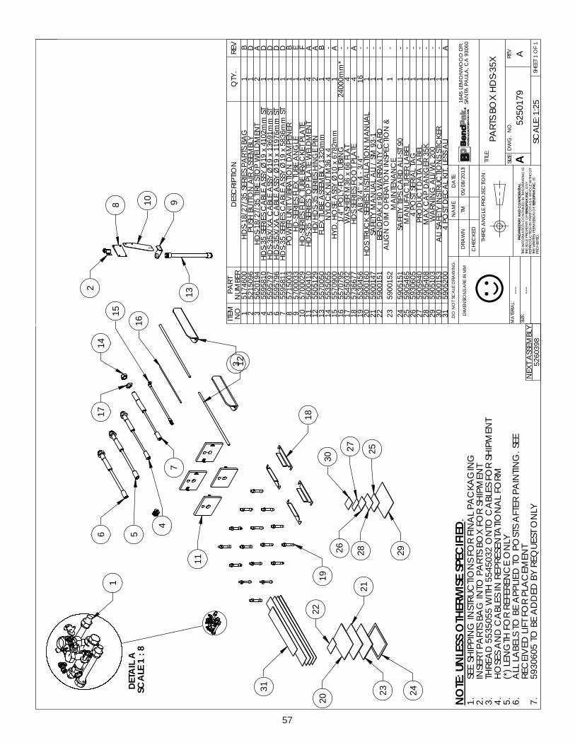
57
ALI
ATED8:
1EL
ACS
1
91
11
716 5
4
41
21
51 61
3
7
2
8
01 931
02
12
32 42
22
13
81
0362
7282
52
92
.
A
MM
NI ERA SN
OISNE
MID :EZIS
:LAIRET
AM
GNI
WAR
D ELA
CS TO
N O
D
SI
GNI
WAR
D SIHT
NI DE
NIATN
OC
NOITA
MROF
NI EHT
FO YTREP
ORP ELOS E
HT Y
NA
TUO
HTIW EL
OH
W A S
A RO TR
AP NI
NOIT
CUD
ORPER F
O N
OISSIMREP
NETTIRW E
HT SI
.DETIBIH
ORP52:1:ELA
CS1 F
O 1 TEEHS
VER.
ON .
GW
DEZIS
:ELTIT
EM
AN
ETA
D
DEKCEH
C
NW
ARD
.RD
DO
OW
NO
MEL 546106039
AC ,
ALUAP
ATN
ASMT
3102 /80/50
NOIT
CEJORP EL
GN
A DRIHT
A9710525
X53-SD
H XOB STR
AP
GNI
GAK
CAP L
ANIF R
OF SN
OITCURTS
NI G
NIPPIHS EES
.1T
NEMPI
HS ROF X
OB STRAP
OTNI
GAB STR
AP TRESNI
.2T
NEMPI
HS ROF SELB
AC
OTN
O 2305455 HTI
W 5505355 D
AERHT
.3MR
OF LA
NOIT
ATNESERPER
NI SELBA
C D
NA SES
OH
.4YL
NO E
CNEREFER R
OF HT
GNEL )*(
.5 EES .
GNIT
NIAP RETF
A STSOP
OT DEILPP
A EB OT SLEB
AL LLA
.6T
NEME
CALP R
OF TFIL DE
VIECER
YLN
O TSEUQER YB
DED
DA EB
OT 5060395.7
DEIFICEPS
ESIWRE HT
OSSEL
NU:ETO
N
☺L
AITNEDIF
NO
CD
NA
YRATEIRPORP
.C
NIK
APDNEB
.C
NIK
APDNEB
YLBMESS
A TXEN
8930625
METIO
N TR
APREB
MUN
NOITPIR
CSED
.YTQ
VER1
0064715G
AB STRAP SEIRES 53/72/81-S
DH
1B
26905125
YLBMESS
A RIA
NOTTUB
HSUP1
D3
4910265T
NEM
DLEW P
OTS ERIT 53/72/81-SDH
2A
4018595 5
TS m
m2014 x 91Ø YSS
A ELBA
C SEIRES 53-SDH
1D
57975955
TS m
m19631 x 91Ø YSS
A ELBA
C AX/X53-S
DH
1D
66975955
TS m
m67911 x 91Ø YSS
A ELBA
C AX/X53-S
DH
1D
71185955
TS m
m6385 x 91Ø YSS
A ELBA
C SEIRES 53-SDH
1D
83005175
RENEP
MA
D N
OITARBI
V TINU RE
WOP
1B
9330007 5
ELG
NA EBUT XELF SEIRES-
DH1
E01
9200075ET
ALP TEKC
ARB EBUT XELF SEIRES-D
H1
F11
0140065T
NEM
DLEW ET
ALP POT SEIRES 53-S
DH4
A21
9215055NIP E
GNIH SEIRES 53-S
DH/
DH2
A31
050075 5m
m0231 YLBMESS
A EBUT XELF1
B41
55053554 x 63
M TUN K
COLY
N4
-51
0090755m
m2876 x 01Ø YSS
A ESO
H .DYH
1A
615970755
GNIBUT
OLF-YLOP "4/1
*m
m00042-
712305455
TALF 66 x 63
M REHS
AW
4-
81776637 5
ETALP T
OOF SEIRES S
DH
4A
916540355
"4/3 - 4 x "4/3 BA
61-
020610095
LAU
NA
M N
OITALL
ATSNI SEIRES K
CURT SDH
1-
127410095
1-39 MS / IL
A LAU
NA
M YTEFAS
1-
22151009 5
DRA
C YTN
ARRA
W 09# K
APD
NEB1
-32
2510095
& N
OITCEPS
NI N
OITAREP
O MI
O N
GILA
EC
NA
NETNI
AM
1-
421515095
09 TS-ILA
DRA
C SPIT YTEFAS
1-
525645095
LEBAL RERUT
CAFU
NA
M1
-62
5060395G
AT LAIRES TS
OP 41
-72
0495095LEB
AL AT
AD T
CUD
ORP1
-82
804509 5K53 RE
GN
AD P
AC X
AM
1-
923015095
002 LW/IL
A G
NINR
AW
1-
033510095
REKCITS S
NOIT
CURTSNI YTEF
AS ILA
1-
130025095
ILA SSEL ,TIK L
ACE
D TSOP 4
1A
NOISI
VERVER
NOITPIR
CSED
ETA
DYB
DETIDE
#O
CEA
8010525 M
ORF DE
VIRED ,ES
AELER N
OITCU
DORP
3102/80/50MT
39500
--- ---

58
FLI
ATED2:
1EL
ACS
5161
41
ELI
ATED5:
1EL
ACS
2
1
DLI
ATED01:
1EL
ACS
71 31
01
9
5
12
21
6
CLI
ATED5:
1EL
ACS8
7
11 4
BLI
ATED5:
1EL
ACS
0281
91
ALI
ATED5:
1EL
ACS
3
22
.A
MM
NI ERA S
NOIS
NEMI
D :EZIS
:LAIRET
AM
GNI
WAR
D ELA
CS TO
N O
D
SI
GNI
WAR
D SIHT
NI DE
NIATN
OC
NOITA
MROF
NI EHT
FO YTREP
ORP ELOS E
HT Y
NA
TUO
HTIW EL
OH
W A S
A RO TR
AP NI
NOIT
CUD
ORPER F
O N
OISSIMREP
NETTIRW E
HT SI
.DETIBIH
ORP05:1:ELA
CS1 F
O 1 TEEHS
VER.
ON .
GW
DEZIS
:ELTIT
EM
AN
ETA
D
DEKCEH
C
NW
ARD
.RD
DO
OW
NO
MEL 546106039
AC ,
ALUAP
ATN
ASC
A9002/60/50
NOIT
CEJORP EL
GN
A DRIHT
B0064715
53/72/81-SD
HG
AB STRAP SEIRES
GNI
GAK
CAP L
ANIF R
OF SN
OITCURTS
NI G
NIPPIHS EES
.1DEIFI
CEPSESI
WREHTO
SSELNU:ET
ON
☺L
AITNEDIF
NO
CD
NA
YRATEIRPORP
.C
NIK
APDNEB
.C
NIK
APDNEB
NOISI
VERVER
NOITPIR
CSED
ETA
DYB
DETIDE
#O
CEA
ESAELER
NOIT
CUD
ORP9002/60/50
CA
14200B
100-B200-B300-B
5355455 )02( DE
DD
AYLB
MESSA TXE
N DET
ADPU
YLBMESS
A TXEN
DETA
DPUSEILB
MESSA TXE
N DET
ADPU
9002/22/212102/52/902102/03/703102/02/50
CA MT MT MT
62300545005350039500
ON
METIREB
MUN TR
APN
OITPIRCSE
DYT
QVER
10550555
TPN 60-
CIJ 60- BLE GTF
1-
24000555
TPN 8/3 S
NI EBUT 4/1 BLE GTF
2-
32305055
SS m
m81 PILC R
OTOR
4-
41005355
LN 52.1 x 8
M TUN
4-
53470355
08 x 5.2 x 02M BH
H4
-6
0020355m
m051 x 5.2 x 81M B
HH4
-7
010035552 x 52.1 x 8
M BHH
4-
83810555
BRO L60-
CIJ 60- BLE GTF
1-
92435455
TALF 81
M REHS
AW
4-
010535455
LS 82 x 81M RE
HSA
W4
-11
0435455T
ALF 42x 8M RE
HSA
W4
-21
7105355L
N 5.2 x 02M TU
N4
-31
60153555.2 x 81
M TUN XEH
4-
410105355
7.0 X 4M ,tu
N2
-51
8000355m
m21 x m
m7.0 x 4M S
CHS2
-61
9005455m
m8.0 x m
m9Ø x 3.4
Ø ,REHSA
W2
-71
9840555S
NI EBUT 4/1-4/1-4/1 EET GTF
3-
811435455
TALF 02
Ø x 01M REHS
AW
8-
918370355
52 x 5.1 x 01M BH
H8
-02
3105355L
N 5.1 x 01M TU
N8
-12
3435455T
ALF 02M ,RE
HSA
W4
-22
5355455STFIL R
OF MIHS REHS
AW
C02
-
YLBMESS
A TXEN
9510525261052507105252710525571052577105259710525
--- ---

59

For Parts Or ServiceContact:
BendPak Inc. / Ranger Products1645 Lemonwood Dr.
Santa Paula, CA. 93060
Tel: 1-805-933-9970Toll Free: 1-800-253-2363
Fax: 1-805-933-9160
www.bendpak.com
pn# 5900160