Embed Size (px)
Citation preview
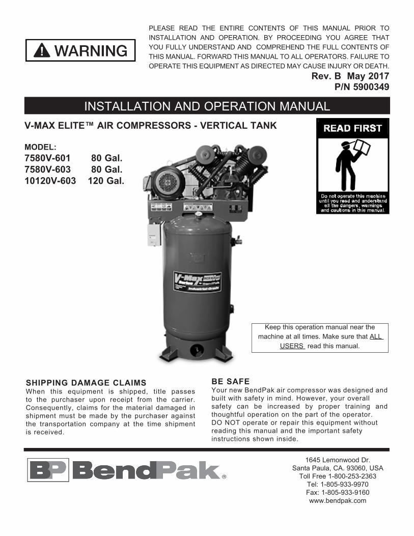
V-MAX ELITE™ AIR COMPRESSORS - VERTICAL TANK
MODEL: 7580V-601 80 Gal.7580V-603 80 Gal.10120V-603 120 Gal.
INSTALLATION AND OPERATION MANUAL
SHIPPING DAMAGE CLAIMSWhen this equipment is shipped, title passes to the purchaser upon receipt from the carrier. Consequently, claims for the material damaged in shipment must be made by the purchaser against the transportation company at the time shipment is received.
BE SAFEYour new BendPak air compressor was designed and built with safety in mind. However, your overallsafety can be increased by proper training and thoughtful operation on the part of the operator. DO NOT operate or repair this equipment without reading this manual and the important safety instructions shown inside.
1645 Lemonwood Dr.Santa Paula, CA. 93060, USA
Toll Free 1-800-253-2363Tel: 1-805-933-9970Fax: 1-805-933-9160www.bendpak.com
Keep this operation manual near the machine at all times. Make sure that ALL
USERS read this manual.
PLEASE READ THE ENTIRE CONTENTS OF THIS MANUAL PRIOR TO INSTALLATION AND OPERATION. BY PROCEEDING YOU AGREE THAT YOU FULLY UNDERSTAND AND COMPREHEND THE FULL CONTENTS OF THIS MANUAL. FORWARD THIS MANUAL TO ALL OPERATORS. FAILURE TO OPERATE THIS EQUIPMENT AS DIRECTED MAY CAUSE INJURY OR DEATH.
Rev. B May 2017 P/N 5900349
2
DESCRIPTIONAir compressor units are intended to provide compressed air to power pneumatic tools, operate spray guns and supply air for pneumatic valves and actuators. The pumps supplied with these units have oil lubricated bearings. A small amount of oil carryover is present in the compressed air stream. Applications requiring air free of oil vapor should have the appropriate filter installed. The air compressor units are to be mounted on a level floor per the instructions provided. Any other use of these units will void the warranty and the manufacturer will not be responsible for problems or damages resulting from such misuse.
SAFETY GUIDELINESThis manual contains information that is very important to know and understand. This information is provided for SAFETY and to PREVENT EQUIPMENT PROBLEMS. To help recognize this information, observe the following symbols.
Watch for this symbol: It Means: Immediate hazards which will result in severe personal injury or death.
Watch for this symbol: It Means: Hazards or unsafe practices which could result in severe personal injury or death.
Watch for this symbol: It Means: Hazards or unsafepractices which may result in minor personal injury or product or property damage.
INTRODUCTION1. Carefully remove the crating and packing materials. CAUTION! Be careful when cutting steel banding material as items may become loose and fall causing personal harm or injury.
2. Check the voltage, phase and proper amperage requirements for the motor shown on the motor plate. Wiring should be performed by a certified electrician only.
3. Confirm voltage before connecting power to your machine or serious damage to the motor/electronics will result.
BREATHABLE AIR WARNINGThis compressor/pump is NOT equipped and should NOT be used “as is” to supply breathing quality air. For any application of air for human consumption, you must fit the air compressor/pump with suitable in-line safety and alarm equipment. This additional equipment is necessary to properly filter and purify the air to meet minimal specifications for Grade D breathing as described in Compressed Gas Association Commodity Specification G 7.1 - 1966, OSHA 29 CFR 1910. 134, and/or Canadian Standards Associations (CSA).
DISCLAIMER OF WARRANTIESIn the event the compressor is used for the purpose of breathing air application and proper in-line safety and alarm equipment is not simultaneously used, existing warranties are void, and the company disclaims any liability whatsoever for any loss, personal injury or damage!
UNPACKINGAfter unpacking the unit, inspect carefully for any damage that may have occurred during transit. Make sure to tighten fittings, bolts, etc., before putting unit into service.
Do not operate unit if damaged during shipping, handling or use. Damage may result in bursting and cause injury or property damage.
Failure to follow danger, warning, and caution instructions may lead to serious personal injury or death to operator or bystander or damage to property. Do not operate this machine until you read and understand all the dangers, warnings and cautions in this manual.
For additional copiesor further information, contact:
BendPak Inc. / Ranger Products1645 Lemonwood Dr.,
Santa Paula, CA. 93060 1-805-933-9970
www.bendpak.com
3
GENERAL SAFETYSince the air compressor and other components (material pump, spray guns, filters, lubricators, hoses, etc.) may be under high pressure and be subject to explosions, the following safety precautions must be observed at all times:
1. READ AND UNDERSTAND all safety warning procedures before installation and operation.
2. KEEP HANDS AND FEET CLEAR. Remove hands and feet from any moving parts.
3. KEEP WORK AREA CLEAN. Cluttered work areas invite injuries.
4. Consider work area environment. Do not expose equipment to rain . DO NOT use in damp or wet locations. Keep area well lighted.
5. ONLY TRAINED OPERATORS should operate this equipment. All non-trained personnel should be kept away from work area. Never let non-trained personnel come in contact with, or operate machine.
6. USE MACHINE CORRECTLY. Use machine in the proper manner. Never use adapters other than what is approved by the manufacturer.
7. DO NOT override or disable safety valves and/or devices.
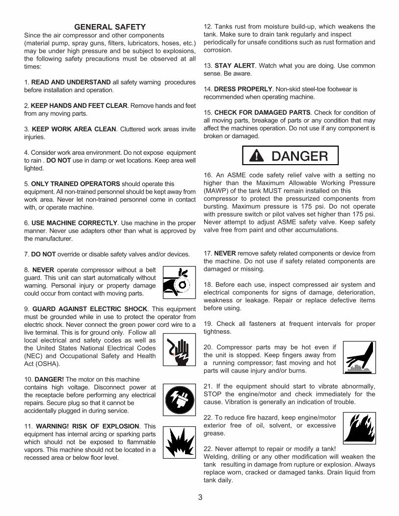
8. NEVER operate compressor without a belt guard. This unit can start automatically without warning. Personal injury or property damage could occur from contact with moving parts.
9. GUARD AGAINST ELECTRIC SHOCK. This equipment must be grounded while in use to protect the operator from electric shock. Never connect the green power cord wire to a live terminal. This is for ground only. Follow all local electrical and safety codes as well as the United States National Electrical Codes (NEC) and Occupational Safety and Health Act (OSHA).
10. DANGER! The motor on this machine contains high voltage. Disconnect power at the receptacle before performing any electrical repairs. Secure plug so that it cannot be accidentally plugged in during service.
11. WARNING! RISK OF EXPLOSION. This equipment has internal arcing or sparking parts which should not be exposed to flammable vapors. This machine should not be located in a recessed area or below floor level.
12. Tanks rust from moisture build-up, which weakens the tank. Make sure to drain tank regularly and inspect periodically for unsafe conditions such as rust formation and corrosion.
13. STAY ALERT. Watch what you are doing. Use common sense. Be aware.
14. DRESS PROPERLY. Non-skid steel-toe footwear isrecommended when operating machine.
15. CHECK FOR DAMAGED PARTS. Check for condition of all moving parts, breakage of parts or any condition that may affect the machines operation. Do not use if any component is broken or damaged.
16. An ASME code safety relief valve with a setting no higher than the Maximum Allowable Working Pressure (MAWP) of the tank MUST remain installed on this compressor to protect the pressurized components from bursting. Maximum pressure is 175 psi. Do not operate with pressure switch or pilot valves set higher than 175 psi. Never attempt to adjust ASME safety valve. Keep safety valve free from paint and other accumulations.
17. NEVER remove safety related components or device from the machine. Do not use if safety related components are damaged or missing.
18. Before each use, inspect compressed air system and electrical components for signs of damage, deterioration, weakness or leakage. Repair or replace defective items before using.
19. Check all fasteners at frequent intervals for proper tightness.
20. Compressor parts may be hot even if the unit is stopped. Keep fingers away from a running compressor; fast moving and hot parts will cause injury and/or burns.
21. If the equipment should start to vibrate abnormally, STOP the engine/motor and check immediately for the cause. Vibration is generally an indication of trouble.
22. To reduce fire hazard, keep engine/motor exterior free of oil, solvent, or excessive grease.
22. Never attempt to repair or modify a tank! Welding, drilling or any other modification will weaken the tank resulting in damage from rupture or explosion. Always replace worn, cracked or damaged tanks. Drain liquid from tank daily.
4
SPRAYING PRECAUTIONS
1. Fast moving air will stir up dust and debris which may be harmful. Release air slowly when draining moisture or depressurizing the compressor system.
2. Do not spray flammable materials in the vicinity of open flame or near ignition sources including the compressor unit. Do not smoke when spraying paint, insecticides, or other flammable substances.
3. Use a face mask/respirator when spraying and spray in a well ventilated area to prevent health and fire hazards.
4. Do not direct paint or other sprayed material at thecompressor. Locate compressor as far away from the spraying area as possible to minimize overspray accumulation on the compressor.
5. When spraying or cleaning with solvents or toxic chemicals, follow the instructions provided by the chemical manufacturer.
INSTALLATION
Disconnect, tag, and lock out power source then release all pressure from the system before attempting to install, service, relocate or perform any maintenance.
Do not lift or move unit without appropriately rated equipment. Be sure the unit is securely attached to lifting device used.
Do not lift unit by holding onto tubes or coolers.
Never use the wood shipping skids for mounting the compressor.
Install and operate unit at least 24” from any obstructions in a clean, well ventilated area. The surrounding air temperature should not exceed 100* F. This will ensure an unobstructed flow of air to cool compressor and allow adequate space for maintenance.
Do not locate the compressor air inlet near steam, paint spray, sandblast areas or any other source of contamination.
NOTE: If compressor operates in a hot, moist environment, supply compressor pump with clean, dry outside air. Supply air should be piped in from external sources.
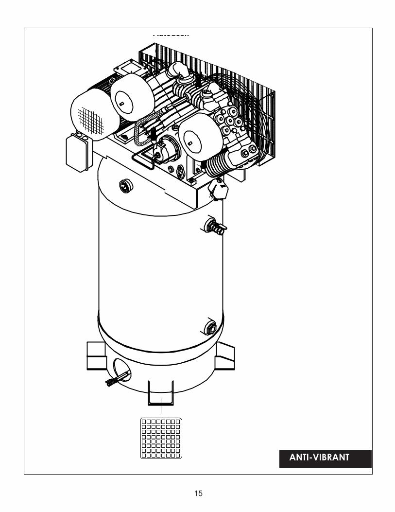
TANK MOUNTING
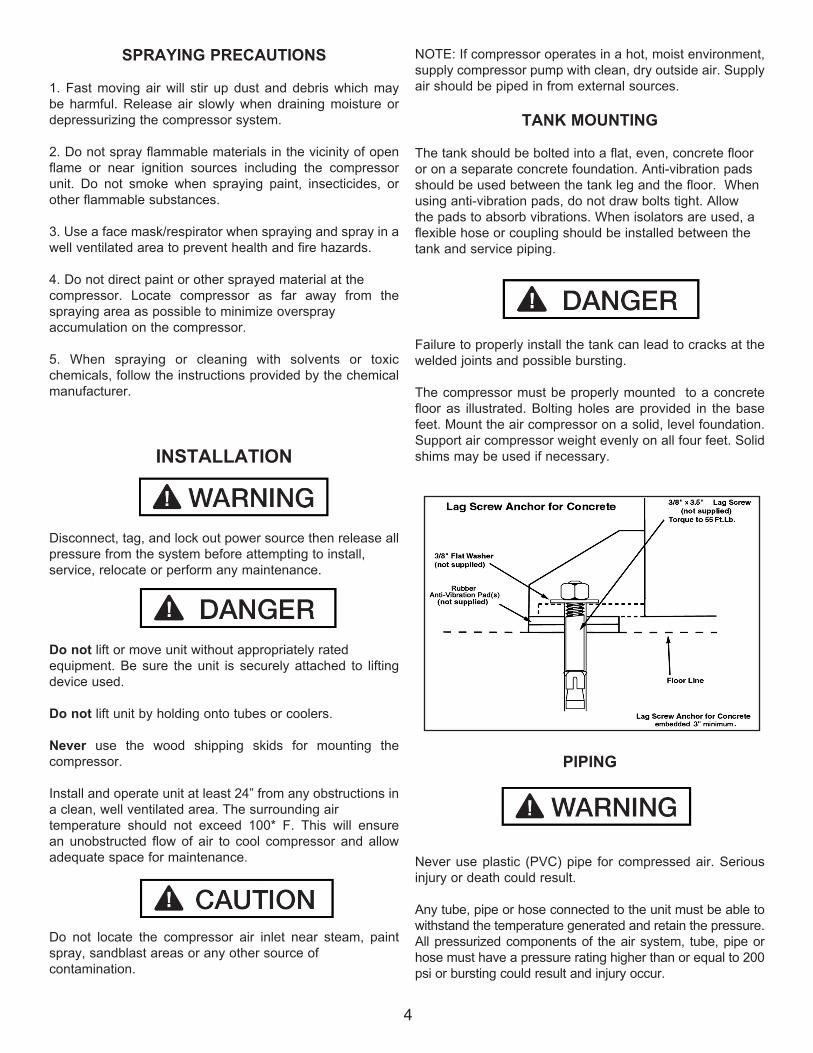
The tank should be bolted into a flat, even, concrete floor or on a separate concrete foundation. Anti-vibration pads should be used between the tank leg and the floor. When using anti-vibration pads, do not draw bolts tight. Allow the pads to absorb vibrations. When isolators are used, a flexible hose or coupling should be installed between the tank and service piping.
Failure to properly install the tank can lead to cracks at the welded joints and possible bursting.
The compressor must be properly mounted to a concrete floor as illustrated. Bolting holes are provided in the base feet. Mount the air compressor on a solid, level foundation. Support air compressor weight evenly on all four feet. Solid shims may be used if necessary.
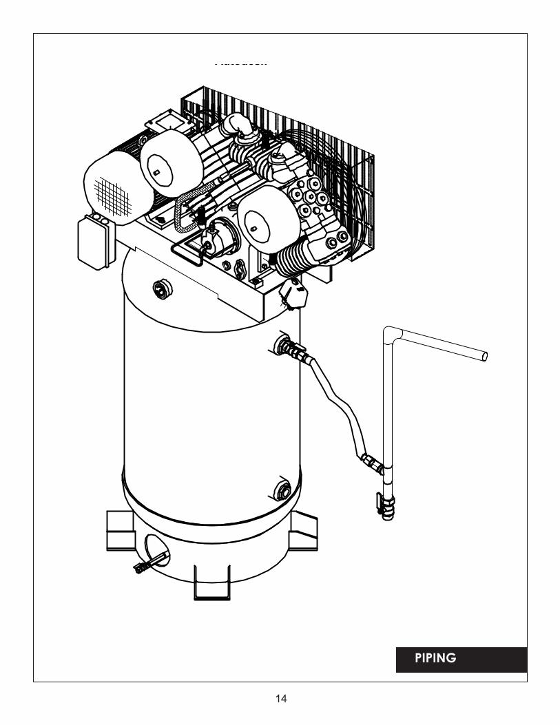
PIPING
Never use plastic (PVC) pipe for compressed air. Serious injury or death could result.
Any tube, pipe or hose connected to the unit must be able to withstand the temperature generated and retain the pressure. All pressurized components of the air system, tube, pipe or hose must have a pressure rating higher than or equal to 200 psi or bursting could result and injury occur.
Connect piping system to tank using the same size fitting asthe discharge port.
Pipe thread lubricant must be used on all male pipe threads, and all joints are to be made up tight, since small leaks in the piping system are the largest single cause of high operating costs. All piping should be sloped to an accessible drain point and all outlets should be taken from the top of the main distribution air line so that moisture cannot enter the outlet.
INSTALLING A SHUT-OFF VALVE
A shut-off valve should be installed on the discharge port of the tank to control the air flow out of the tank. The valve should be located between the tank and the piping system.
Never install a shut-off valve between the compressor pump and the tank. Personal injury and/or equipment damage may occur. Never use a reducer in discharge piping.
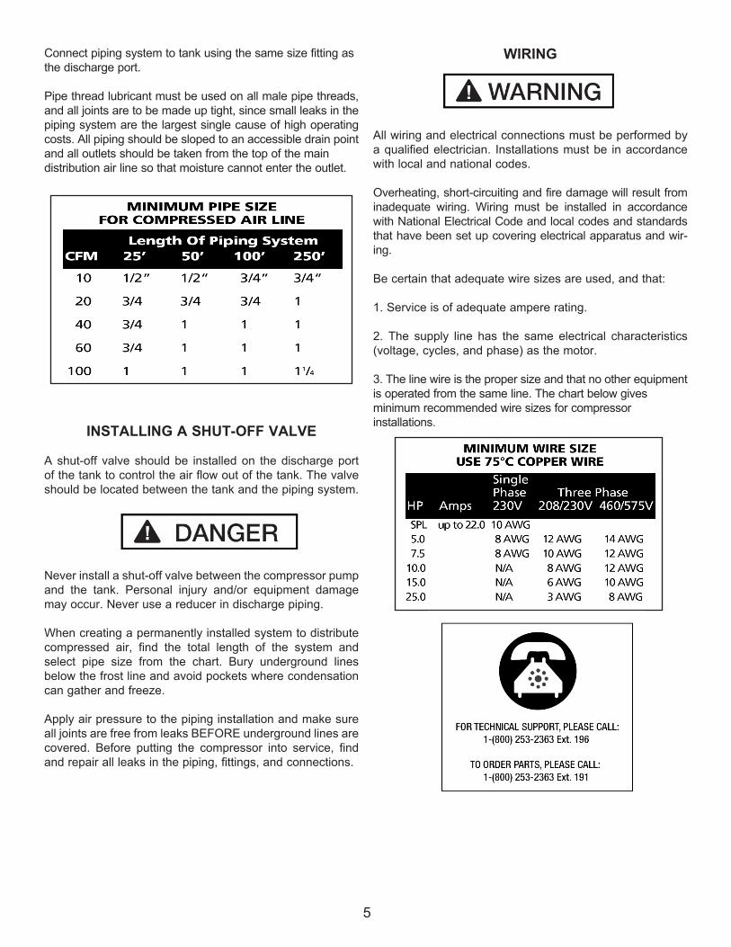
When creating a permanently installed system to distribute compressed air, find the total length of the system and select pipe size from the chart. Bury underground lines below the frost line and avoid pockets where condensation can gather and freeze.
Apply air pressure to the piping installation and make sure all joints are free from leaks BEFORE underground lines are covered. Before putting the compressor into service, find and repair all leaks in the piping, fittings, and connections.
WIRING
All wiring and electrical connections must be performed by a qualified electrician. Installations must be in accordance with local and national codes.
Overheating, short-circuiting and fire damage will result from inadequate wiring. Wiring must be installed in accordance with National Electrical Code and local codes and standards that have been set up covering electrical apparatus and wir-ing.
Be certain that adequate wire sizes are used, and that:
1. Service is of adequate ampere rating.
2. The supply line has the same electrical characteristics (voltage, cycles, and phase) as the motor.
3. The line wire is the proper size and that no other equipment is operated from the same line. The chart below gives minimum recommended wire sizes for compressor installations.
5
6
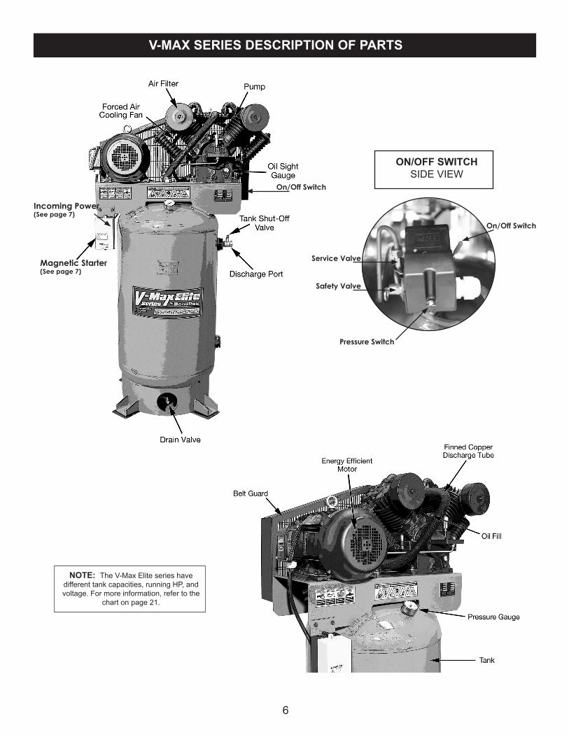
V-MAX SERIES DESCRIPTION OF PARTS
Incoming Power (See page 7)
On/Off Switch
NOTE: The V-Max Elite series have different tank capacities, running HP, and voltage. For more information, refer to the
chart on page 21.
Safety Valve
Service Valve
Pressure Switch
On/Off Switch
ON/OFF SWITCHSIDE VIEW
Magnetic Starter (See page 7)
7
Recommended wire sizes may be larger than the minimum set up by local ordinances. If so, the larger size wire should be used to prevent excessive line voltage drop. The additional wire cost is very small compared with the cost of repairing or replacing a motor electrically “starved” by the use of supply wires which are too small.
Improperly grounded electrical components are shock hazards. Make sure all the components are properly grounded to prevent death or serious injury.
This product must be grounded. Grounding reduces the risk of electrical shock by providing an escape wire for the electric current if a short circuit occurs. This product must be installed and operated with a power cord or cable that has a grounding wire.
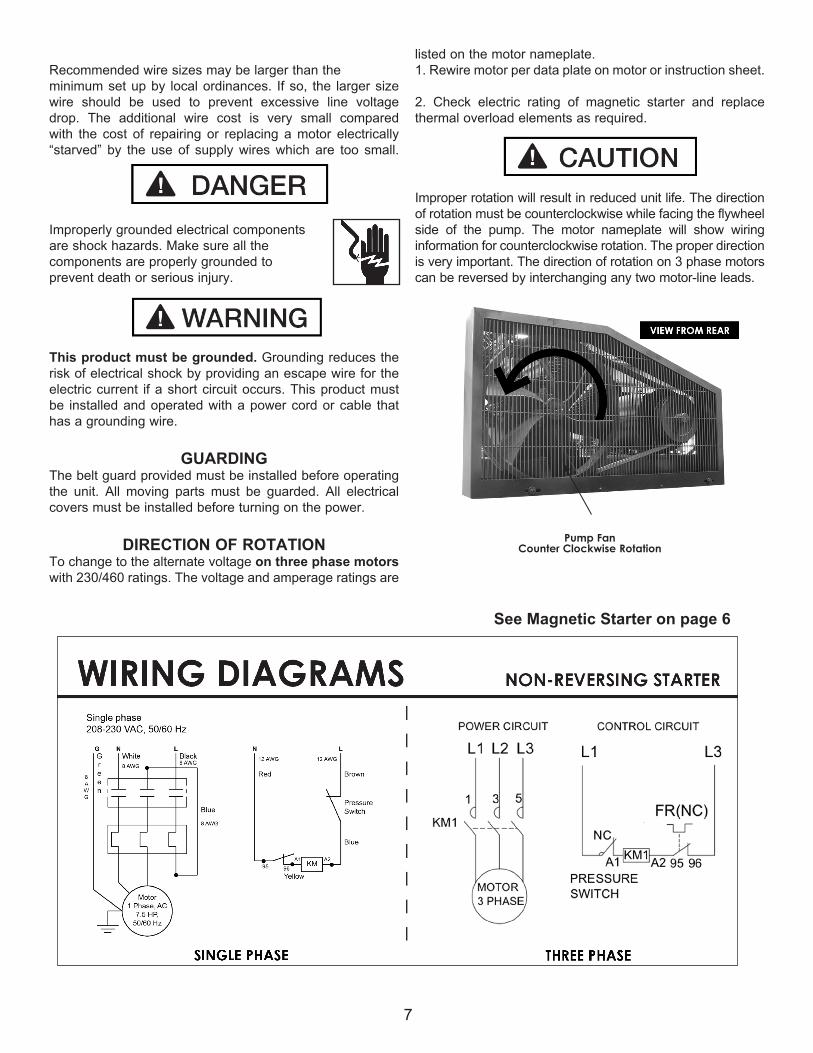
GUARDINGThe belt guard provided must be installed before operating the unit. All moving parts must be guarded. All electrical covers must be installed before turning on the power.
DIRECTION OF ROTATIONTo change to the alternate voltage on three phase motors with 230/460 ratings. The voltage and amperage ratings are
listed on the motor nameplate.1. Rewire motor per data plate on motor or instruction sheet.
2. Check electric rating of magnetic starter and replace thermal overload elements as required.
Improper rotation will result in reduced unit life. The direction of rotation must be counterclockwise while facing the flywheel side of the pump. The motor nameplate will show wiring information for counterclockwise rotation. The proper direction is very important. The direction of rotation on 3 phase motors can be reversed by interchanging any two motor-line leads.
Pump FanCounter Clockwise Rotation
See Magnetic Starter on page 6
8
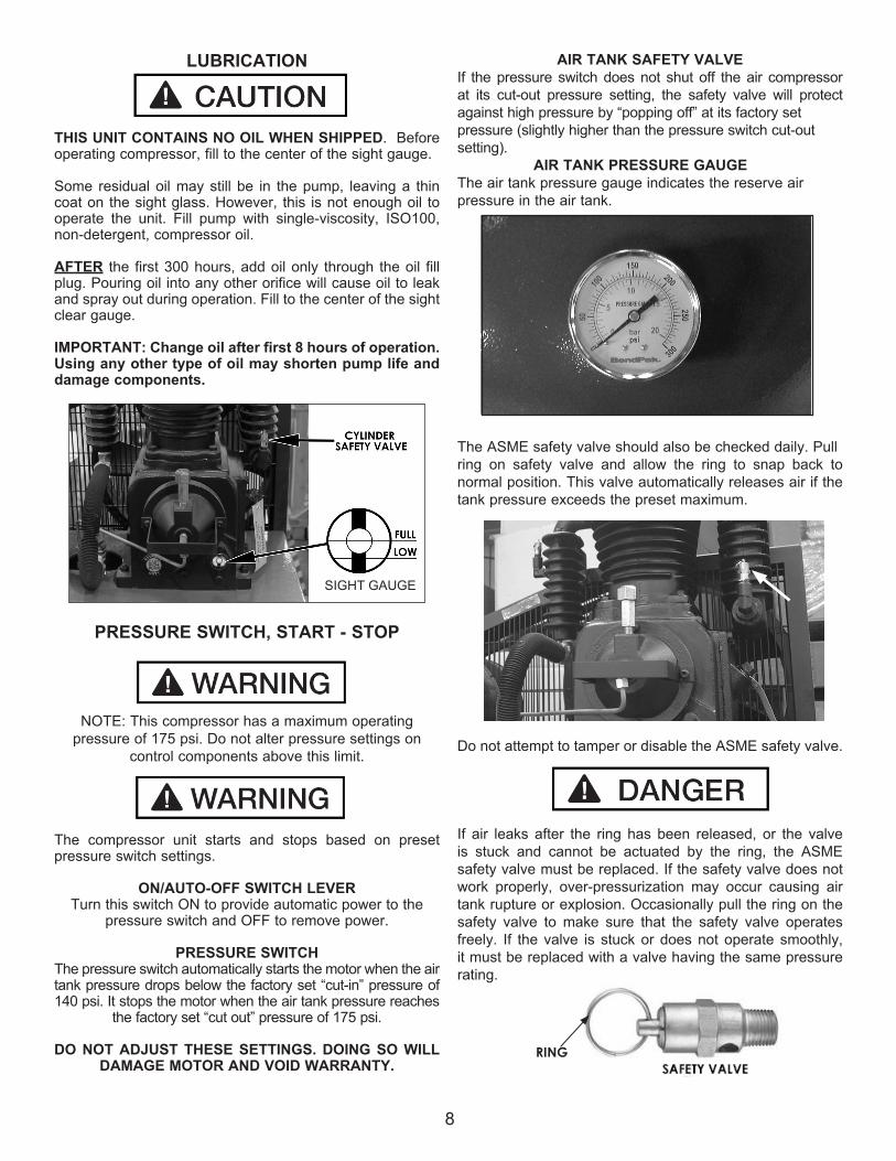
LUBRICATION
THIS UNIT CONTAINS NO OIL WHEN SHIPPED. Before operating compressor, fill to the center of the sight gauge.
Some residual oil may still be in the pump, leaving a thin coat on the sight glass. However, this is not enough oil to operate the unit. Fill pump with single-viscosity, ISO100, non-detergent, compressor oil.
AFTER the first 300 hours, add oil only through the oil fill plug. Pouring oil into any other orifice will cause oil to leak and spray out during operation. Fill to the center of the sight clear gauge.
IMPORTANT: Change oil after first 8 hours of operation. Using any other type of oil may shorten pump life and damage components.
PRESSURE SWITCH, START - STOP
NOTE: This compressor has a maximum operating pressure of 175 psi. Do not alter pressure settings on
control components above this limit.
The compressor unit starts and stops based on preset pressure switch settings.
ON/AUTO-OFF SWITCH LEVERTurn this switch ON to provide automatic power to the
pressure switch and OFF to remove power.
PRESSURE SWITCHThe pressure switch automatically starts the motor when the air tank pressure drops below the factory set “cut-in” pressure of 140 psi. It stops the motor when the air tank pressure reaches
the factory set “cut out” pressure of 175 psi.
DO NOT ADJUST THESE SETTINGS. DOING SO WILL DAMAGE MOTOR AND VOID WARRANTY.
AIR TANK SAFETY VALVEIf the pressure switch does not shut off the air compressor at its cut-out pressure setting, the safety valve will protect against high pressure by “popping off” at its factory set pressure (slightly higher than the pressure switch cut-out setting). AIR TANK PRESSURE GAUGEThe air tank pressure gauge indicates the reserve air pressure in the air tank.
The ASME safety valve should also be checked daily. Pullring on safety valve and allow the ring to snap back to normal position. This valve automatically releases air if the tank pressure exceeds the preset maximum.
Do not attempt to tamper or disable the ASME safety valve.
If air leaks after the ring has been released, or the valve is stuck and cannot be actuated by the ring, the ASME safety valve must be replaced. If the safety valve does not work properly, over-pressurization may occur causing air tank rupture or explosion. Occasionally pull the ring on the safety valve to make sure that the safety valve operates freely. If the valve is stuck or does not operate smoothly, it must be replaced with a valve having the same pressure rating.
RING
SIGHT GAUGE
9
BREAK-IN PROCEDURES
This procedure is required before the air compressor is put into service, before the hose is installed, the check valve is replaced, or a complete compressor pump is replaced.
Serious damage may result if the following break-in instructions are not closely followed.
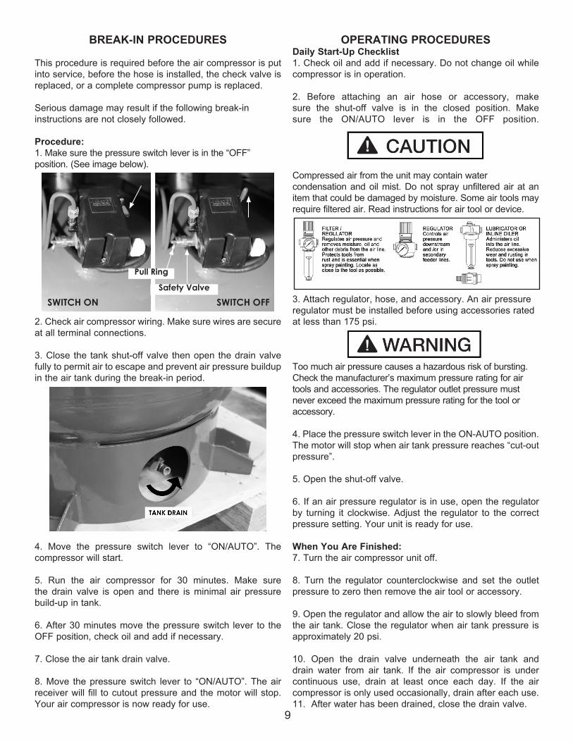
Procedure:1. Make sure the pressure switch lever is in the “OFF” position. (See image below).
2. Check air compressor wiring. Make sure wires are secure at all terminal connections.
3. Close the tank shut-off valve then open the drain valve fully to permit air to escape and prevent air pressure buildup in the air tank during the break-in period.
4. Move the pressure switch lever to “ON/AUTO”. The compressor will start.
5. Run the air compressor for 30 minutes. Make sure the drain valve is open and there is minimal air pressure build-up in tank.
6. After 30 minutes move the pressure switch lever to the OFF position, check oil and add if necessary.
7. Close the air tank drain valve.
8. Move the pressure switch lever to “ON/AUTO”. The air receiver will fill to cutout pressure and the motor will stop. Your air compressor is now ready for use.
OPERATING PROCEDURESDaily Start-Up Checklist1. Check oil and add if necessary. Do not change oil while compressor is in operation.
2. Before attaching an air hose or accessory, make sure the shut-off valve is in the closed position. Make sure the ON/AUTO lever is in the OFF position.
Compressed air from the unit may contain water condensation and oil mist. Do not spray unfiltered air at an item that could be damaged by moisture. Some air tools may require filtered air. Read instructions for air tool or device.
3. Attach regulator, hose, and accessory. An air pressure regulator must be installed before using accessories rated at less than 175 psi. Too much air pressure causes a hazardous risk of bursting. Check the manufacturer’s maximum pressure rating for air tools and accessories. The regulator outlet pressure must never exceed the maximum pressure rating for the tool or accessory.
4. Place the pressure switch lever in the ON-AUTO position. The motor will stop when air tank pressure reaches “cut-out pressure”.
5. Open the shut-off valve.
6. If an air pressure regulator is in use, open the regulator by turning it clockwise. Adjust the regulator to the correct pressure setting. Your unit is ready for use.
When You Are Finished:7. Turn the air compressor unit off.
8. Turn the regulator counterclockwise and set the outlet pressure to zero then remove the air tool or accessory.
9. Open the regulator and allow the air to slowly bleed from the air tank. Close the regulator when air tank pressure is approximately 20 psi.
10. Open the drain valve underneath the air tank and drain water from air tank. If the air compressor is under continuous use, drain at least once each day. If the air compressor is only used occasionally, drain after each use.11. After water has been drained, close the drain valve.
SWITCH OFFSWITCH ON
Pull Ring
Safety Valve
10
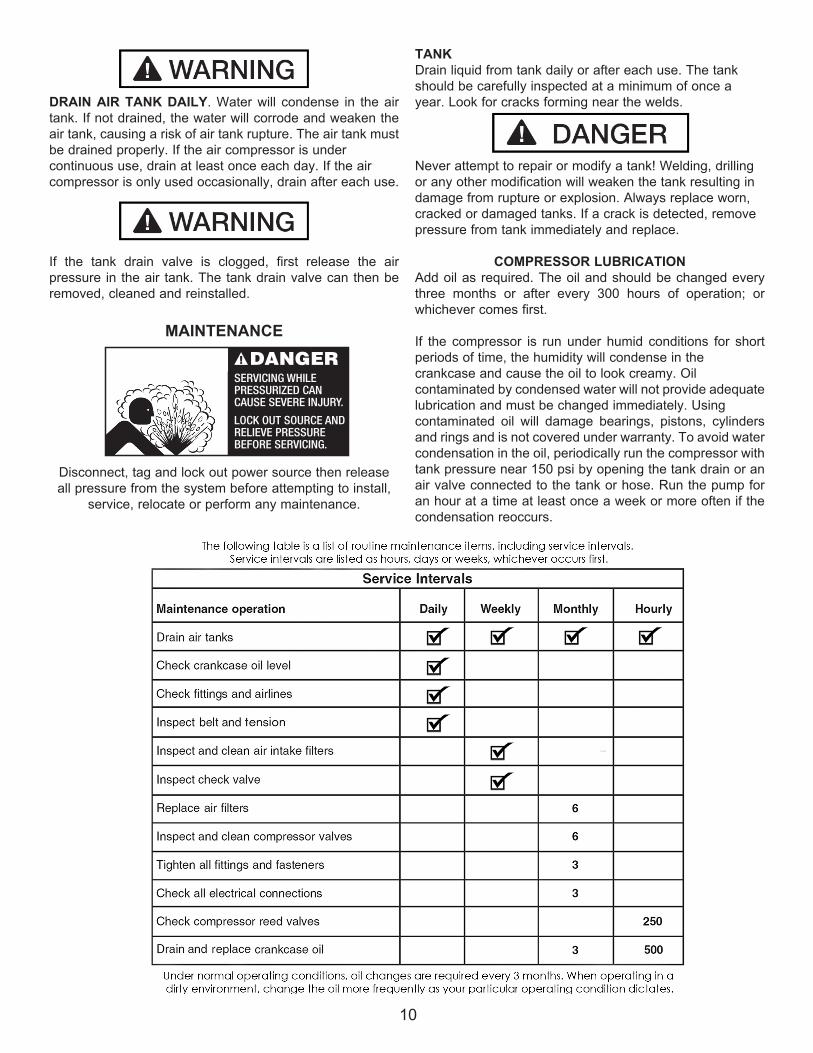
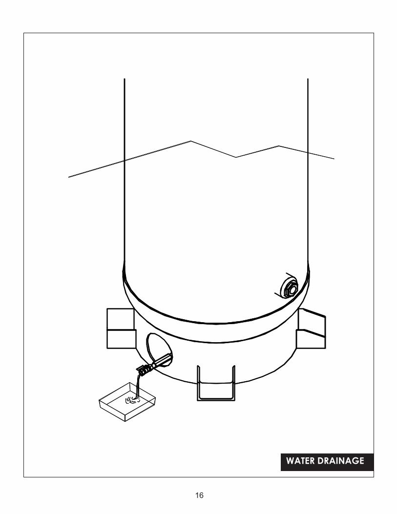
DRAIN AIR TANK DAILY. Water will condense in the air tank. If not drained, the water will corrode and weaken the air tank, causing a risk of air tank rupture. The air tank must be drained properly. If the air compressor is under continuous use, drain at least once each day. If the air compressor is only used occasionally, drain after each use.
If the tank drain valve is clogged, first release the air pressure in the air tank. The tank drain valve can then be removed, cleaned and reinstalled.
MAINTENANCE
Disconnect, tag and lock out power source then release all pressure from the system before attempting to install,
service, relocate or perform any maintenance.
TANK Drain liquid from tank daily or after each use. The tank should be carefully inspected at a minimum of once a year. Look for cracks forming near the welds.
Never attempt to repair or modify a tank! Welding, drilling or any other modification will weaken the tank resulting in damage from rupture or explosion. Always replace worn, cracked or damaged tanks. If a crack is detected, remove pressure from tank immediately and replace.
COMPRESSOR LUBRICATIONAdd oil as required. The oil and should be changed every three months or after every 300 hours of operation; or whichever comes first.
If the compressor is run under humid conditions for short periods of time, the humidity will condense in the crankcase and cause the oil to look creamy. Oil contaminated by condensed water will not provide adequate lubrication and must be changed immediately. Using contaminated oil will damage bearings, pistons, cylinders and rings and is not covered under warranty. To avoid water condensation in the oil, periodically run the compressor with tank pressure near 150 psi by opening the tank drain or an air valve connected to the tank or hose. Run the pump for an hour at a time at least once a week or more often if the condensation reoccurs.
AIR FILTER
DANGERSERVICING WHILE PRESSURIZED CAN CAUSE SEVERE INJURY.
LOCK OUT SOURCE ANDRELIEVE PRESSUREBEFORE SERVICING.
11
Never run the compressor pump without an intake air filter nor with a clogged intake air filter(s). Use compressed air to blow the filters clean. Do not wash or oil the element. If it cannot be blown clean, the filter(s) must be replaced.
Operating compressor with a dirty filter can cause high oil consumption and increase oil contamination in the discharge air.
INTERCOOLER TUBING
Intercooler fins are very sharp. Always wear gloves and use care when you clean or work near the intercooler tubing. Weekly, check the intercooler to be sure all fittings are secure and tight. Blow all dirt, dust and other accumulations from the intercooler fins.
COMPONENTSTurn off all power and use light air pressure to blow dust and foreign material from cylinder head, motor, fan blades, air lines, intercooler and tank on a monthly basis.
When using an air blow gun always wear eye protection and face mask/respirator. Fast moving air will stir up dust and debris which may be harmful.
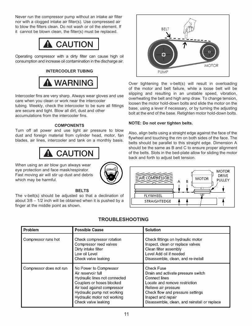
BELTSThe v-belt(s) should be adjusted so that a declination of about 3/8 – 1/2 inch will be obtained when it is pushed by a finger at the middle point as shown.
Over tightening the v-belt(s) will result in overloading of the motor and belt failure, while a loose belt will be slipping and resulting in an unstable speed, vibration, overheating the belt and high amp draw. To change tension, loosen the motor hold-down bolts and slide the motor on the base, using a lever if necessary, or by turning the adjusting bolt at the end of the base. Retighten motor hold-down bolts.
NOTE: Do not over tighten belts.
Also, align belts using a straight edge against the face of the flywheel and touching the rim on both sides of the face. The belts should be parallel to this straight edge. Dimension A should be the same as B and C to ensure proper alignment of the belts. Slots in the bed-plate allow for sliding the motor back and forth to adjust belt tension.
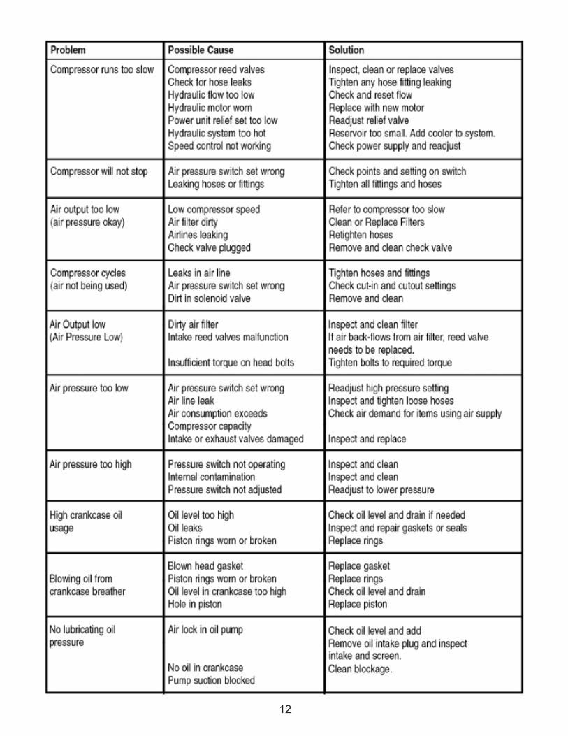
TROUBLESHOOTING
12
13
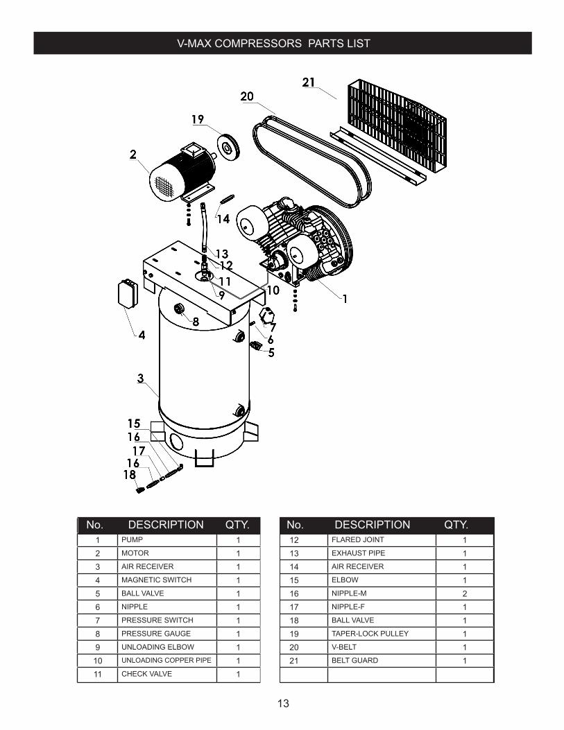
1 PUMP 1 12 FLARED JOINT 12 MOTOR 1 13 EXHAUST PIPE 13 AIR RECEIVER 1 14 AIR RECEIVER 14 MAGNETIC SWITCH 1 15 ELBOW 15 BALL VALVE 1 16 NIPPLE-M 26 NIPPLE 1 17 NIPPLE-F 17 PRESSURE SWITCH 1 18 BALL VALVE 18 PRESSURE GAUGE 1 19 TAPER-LOCK PULLEY 19 UNLOADING ELBOW 1 20 V-BELT 1
10 UNLOADING COPPER PIPE 1 21 BELT GUARD 111 CHECK VALVE 1
No. DESCRIPTION QTY. No. DESCRIPTION QTY.
V-MAX COMPRESSORS PARTS LIST
14
� Autodesk � � � � � � �
� A
utod
esk
��
��
��
�� Autodesk �������
� A
utodesk ��
��
��
�
PIPING
15
� Autodesk � � � � � � �
� A
utod
esk
��
��
��
�� Autodesk �������
� A
utodesk ��
��
��
�
ANTI-VIBRANT
16
� Autodesk � � � � � � �
� A
utod
esk
��
��
��
�
� Autodesk ��������
Autodesk �
��
��
��
WATER DRAINAGE
17
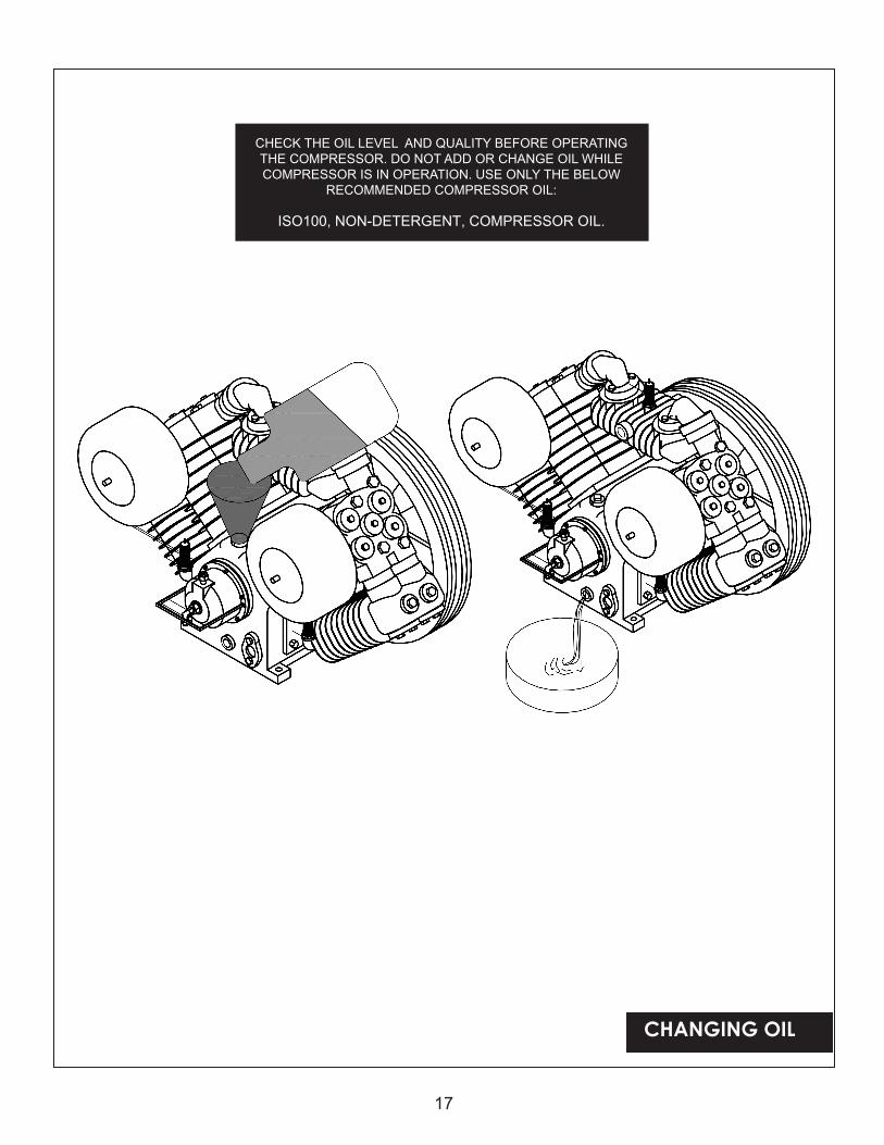
CHANGING OIL
CHECK THE OIL LEVEL AND QUALITY BEFORE OPERATING THE COMPRESSOR. DO NOT ADD OR CHANGE OIL WHILE COMPRESSOR IS IN OPERATION. USE ONLY THE BELOW
RECOMMENDED COMPRESSOR OIL:
ISO100, NON-DETERGENT, COMPRESSOR OIL.
18
� Autodesk � � � � � � ��
Aut
odes
k �
��
��
��
� Autodesk ��������
Autodesk �
��
��
��
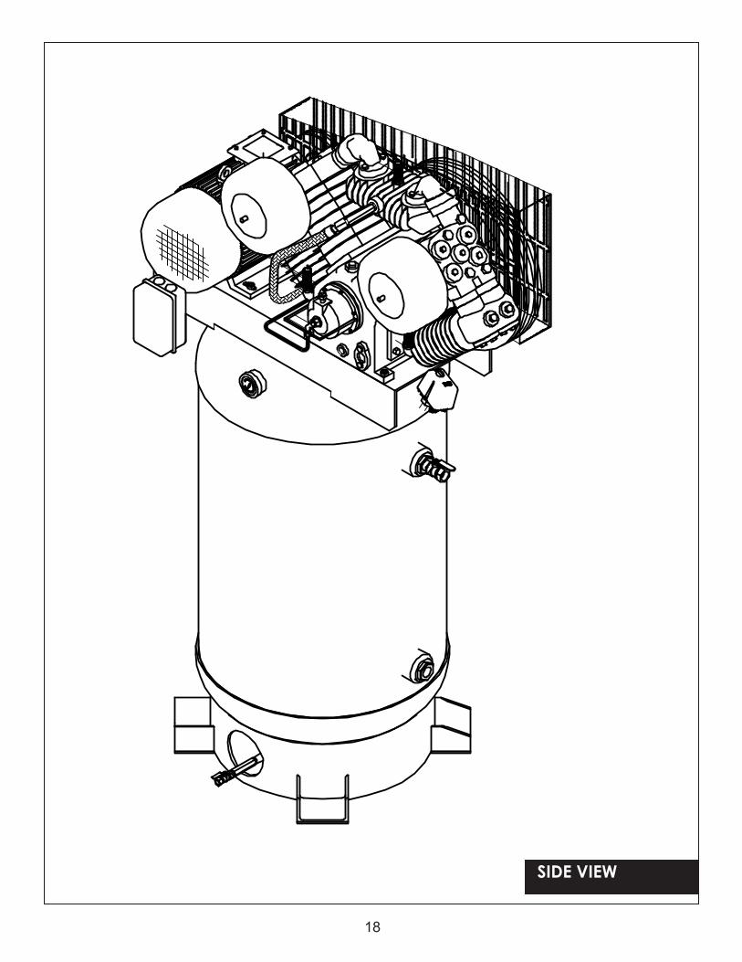
SIDE VIEW
19
� Autodesk � � � � � � �
� A
utod
esk
��
��
��
�� Autodesk �������
� A
utodesk ��
��
��
�
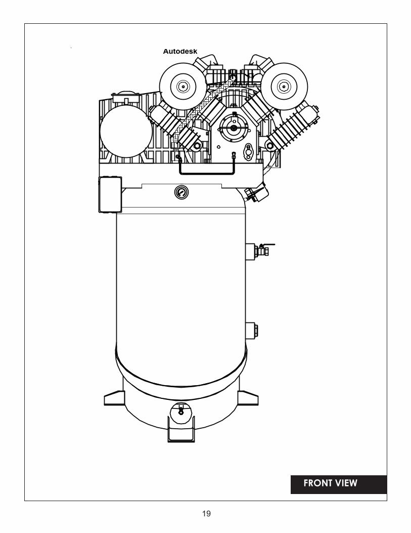
FRONT VIEW
20
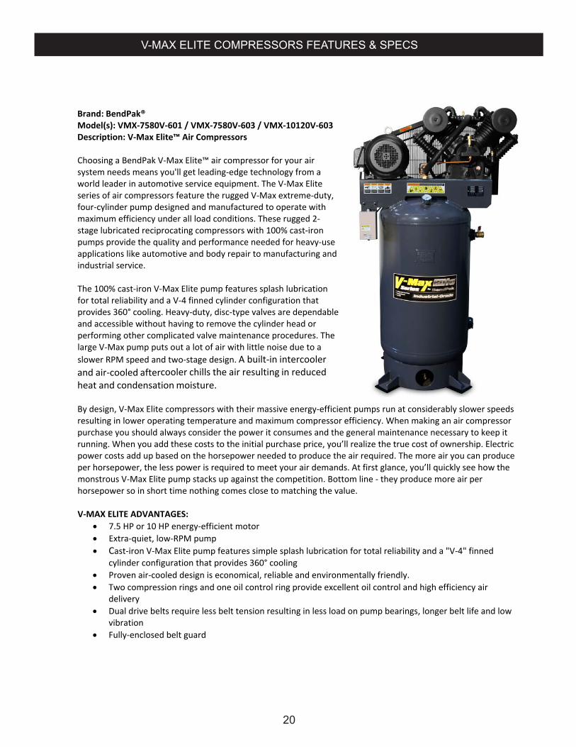
Brand: BendPak® Model(s): VMX‐7580V‐601 / VMX‐7580V‐603 / VMX‐10120V‐603 Description: V‐Max Elite™ Air Compressors Choosing a BendPak V‐Max Elite™ air compressor for your air system needs means you'll get leading‐edge technology from a world leader in automotive service equipment. The V‐Max Elite series of air compressors feature the rugged V‐Max extreme‐duty, four‐cylinder pump designed and manufactured to operate with maximum efficiency under all load conditions. These rugged 2‐stage lubricated reciprocating compressors with 100% cast‐iron pumps provide the quality and performance needed for heavy‐use applications like automotive and body repair to manufacturing and industrial service. The 100% cast‐iron V‐Max Elite pump features splash lubrication for total reliability and a V‐4 finned cylinder configuration that provides 360° cooling. Heavy‐duty, disc‐type valves are dependable and accessible without having to remove the cylinder head or performing other complicated valve maintenance procedures. The large V‐Max pump puts out a lot of air with little noise due to a slower RPM speed and two‐stage design. A built‐in intercooler and air‐cooled aftercooler chills the air resulting in reduced heat and condensation moisture. By design, V‐Max Elite compressors with their massive energy‐efficient pumps run at considerably slower speeds resulting in lower operating temperature and maximum compressor efficiency. When making an air compressor purchase you should always consider the power it consumes and the general maintenance necessary to keep it running. When you add these costs to the initial purchase price, you’ll realize the true cost of ownership. Electric power costs add up based on the horsepower needed to produce the air required. The more air you can produce per horsepower, the less power is required to meet your air demands. At first glance, you’ll quickly see how the monstrous V‐Max Elite pump stacks up against the competition. Bottom line ‐ they produce more air per horsepower so in short time nothing comes close to matching the value. V‐MAX ELITE ADVANTAGES:
7.5 HP or 10 HP energy‐efficient motor Extra‐quiet, low‐RPM pump Cast‐iron V‐Max Elite pump features simple splash lubrication for total reliability and a "V‐4" finned
cylinder configuration that provides 360° cooling Proven air‐cooled design is economical, reliable and environmentally friendly. Two compression rings and one oil control ring provide excellent oil control and high efficiency air
delivery Dual drive belts require less belt tension resulting in less load on pump bearings, longer belt life and low
vibration Fully‐enclosed belt guard
V-MAX ELITE COMPRESSORS FEATURES & SPECS
21
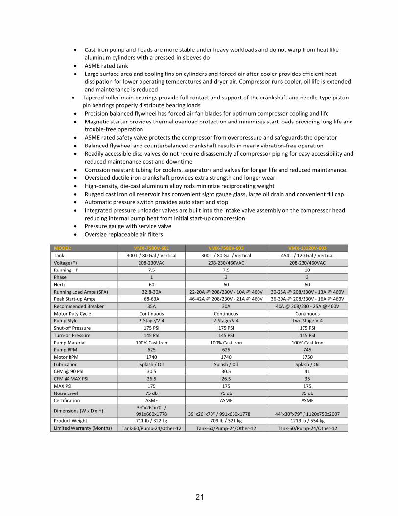
Cast‐iron pump and heads are more stable under heavy workloads and do not warp from heat like aluminum cylinders with a pressed‐in sleeves do
ASME rated tank Large surface area and cooling fins on cylinders and forced‐air after‐cooler provides efficient heat
dissipation for lower operating temperatures and dryer air. Compressor runs cooler, oil life is extended and maintenance is reduced
Tapered roller main bearings provide full contact and support of the crankshaft and needle‐type piston pin bearings properly distribute bearing loads
Precision balanced flywheel has forced‐air fan blades for optimum compressor cooling and life Magnetic starter provides thermal overload protection and minimizes start loads providing long life and
trouble‐free operation ASME rated safety valve protects the compressor from overpressure and safeguards the operator Balanced flywheel and counterbalanced crankshaft results in nearly vibration‐free operation Readily accessible disc‐valves do not require disassembly of compressor piping for easy accessibility and
reduced maintenance cost and downtime Corrosion resistant tubing for coolers, separators and valves for longer life and reduced maintenance. Oversized ductile iron crankshaft provides extra strength and longer wear High‐density, die‐cast aluminum alloy rods minimize reciprocating weight Rugged cast iron oil reservoir has convenient sight gauge glass, large oil drain and convenient fill cap. Automatic pressure switch provides auto start and stop Integrated pressure unloader valves are built into the intake valve assembly on the compressor head
reducing internal pump heat from initial start‐up compression Pressure gauge with service valve Oversize replaceable air filters
MODEL: VMX‐7580V‐601 VMX‐7580V‐603 VMX‐10120V‐603 Tank: 300 L / 80 Gal / Vertical 300 L / 80 Gal / Vertical 454 L / 120 Gal / Vertical Voltage (*) 208‐230VAC 208‐230/460VAC 208‐230/460VAC Running HP 7.5 7.5 10 Phase 1 3 3 Hertz 60 60 60 Running Load Amps (SFA) 32.8‐30A 22‐20A @ 208/230V ‐ 10A @ 460V 30‐25A @ 208/230V ‐ 13A @ 460V Peak Start‐up Amps 68‐63A 46‐42A @ 208/230V ‐ 21A @ 460V 36‐30A @ 208/230V ‐ 16A @ 460V Recommended Breaker 35A 30A 40A @ 208/230 ‐ 25A @ 460V Motor Duty Cycle Continuous Continuous Continuous Pump Style 2‐Stage/V‐4 2‐Stage/V‐4 Two Stage V‐4 Shut‐off Pressure 175 PSI 175 PSI 175 PSI Turn‐on Pressure 145 PSI 145 PSI 145 PSI Pump Material 100% Cast Iron 100% Cast Iron 100% Cast Iron Pump RPM 625 625 745 Motor RPM 1740 1740 1750 Lubrication Splash / Oil Splash / Oil Splash / Oil CFM @ 90 PSI 30.5 30.5 41 CFM @ MAX PSI 26.5 26.5 35 MAX PSI 175 175 175 Noise Level 75 db 75 db 75 db Certification ASME ASME ASME
Dimensions (W x D x H) 39"x26"x70" / 991x660x1778 39"x26"x70" / 991x660x1778 44"x30"x79" / 1120x750x2007
Product Weight 711 lb / 322 kg 709 lb / 321 kg 1219 lb / 554 kg Limited Warranty (Months) Tank‐60/Pump‐24/Other‐12 Tank‐60/Pump‐24/Other‐12 Tank‐60/Pump‐24/Other‐12
22
23
MAINTENANCE / INSPECTION RECORDS
____________________________________________________________________
____________________________________________________________________
____________________________________________________________________
____________________________________________________________________
____________________________________________________________________
____________________________________________________________________
____________________________________________________________________
____________________________________________________________________
____________________________________________________________________
____________________________________________________________________
____________________________________________________________________
____________________________________________________________________
____________________________________________________________________
____________________________________________________________________
____________________________________________________________________
____________________________________________________________________
____________________________________________________________________
____________________________________________________________________
____________________________________________________________________
____________________________________________________________________